
fractures are somewhat variable and must be individualized for each
fracture and patient. The decision for surgery involves an evaluation
of the patient, the fracture, and the surgeon. Patient factors include
age, activity level, type of employment, associated injuries, and
medical co-morbidities. Issues to consider regarding the fracture
include pattern, degree of comminution, bone quality, displacement,
articular impaction, mechanism of injury, condition of soft tissue
around the fracture, and stability of the knee. Surgeon factors that
must be considered when deciding whether to treat a fracture surgically
include surgeon experience, surgical team experience, and available
equipment.
treatment of proximal tibia fractures: open injuries, compartment
syndromes, and fractures associated with vascular injuries. Although
these are absolute indications for surgery, they are not absolute
indications for open reduction and internal fixation (ORIF). In many
fractures associated with these three absolute indications for surgery,
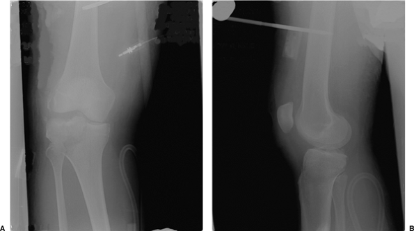
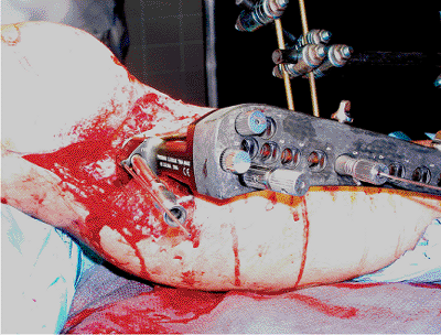
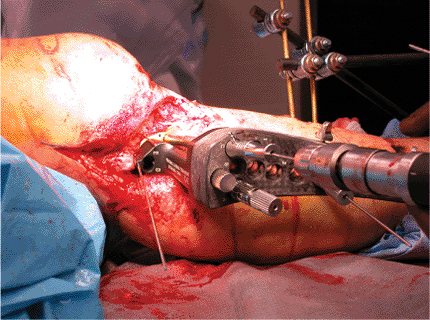
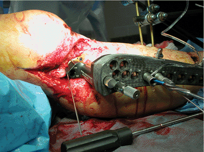
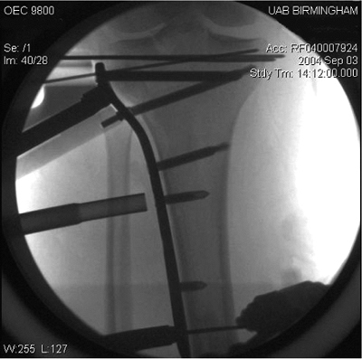
temporary, spanning, external fixation is the initial treatment of
choice (Fig. 27.1). Relative indications for
surgical treatment of proximal tibia fractures include most displaced
bicondylar and medial condyle tibial-plateau fractures; lateral
tibial-plateau fractures that result in knee instability; condylar
widening that exceeds 5 mm; fracture dislocations of the knee;
nonarticular, proximal, tibia fractures that are displaced or unstable;
and any fracture associated with patient or injury factors that will
prevent early mobilization of the knee joint if treated nonoperatively
(1–5).
tibia fracture surgically, the surgeon must decide between conventional
osteosynthesis and locked plating. Specific indications for locked
plating include bicondylar tibial-plateau fractures, marked
comminution, osteopenia or poor bone quality, and a bone gap secondary
to loss of bone along one or both columns of the proximal tibia.
the proximal tibia are identical to those for conventional compression
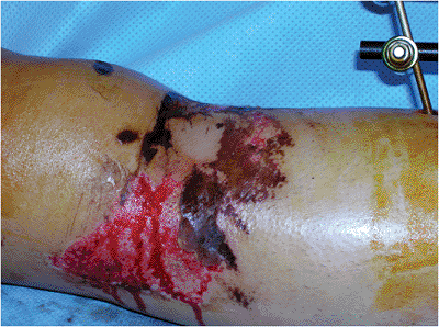
plating of the proximal tibia. The primary contraindication
is a severely damaged soft-tissue envelope (Fig. 27.2)
that makes preceding with surgery a dangerous and high-risk proposal.
In many cases, soft-tissue and skin damage will be a temporary
contraindication for surgery. Delaying surgical treatment for a period
of a few days to a few weeks, until optimal soft-tissue conditions
exist, minimizes complications (3). Additional contraindications for
ORIF include patients with serious medical co-morbidities that make
them poor surgical candidates, and stable fractures with minimal
displacement. Finally, a contraindication for locked plating is any
fracture that can be treated equally well with a conventional
compression plate. Plates designed with fixed-angle locking screws are
expensive compared to compression plates and should be reserved for
fractures that will benefit from locked plating.
 |
|
Figure 27.1. A,B. Spanning external fixator placed for temporary stabilization following a tibial plateau fracture.
|
 |
|
Figure 27.2. Contusions, abrasions, and soft-tissue injury following a high-energy tibial plateau fracture.
|
history and physical examination. One of the crucial steps in
developing a treatment plan is determining whether the fracture
occurred as a result of high- or low-energy trauma. Locked plating will
be used more frequently following high-energy trauma. In cases of
proximal tibia fractures that result from high-energy trauma, great
care must be taken to assess the skin and soft tissues, the
compartments of the leg, the patient’s neurological status, and the
vascular supply to the distal leg. Careful evaluation of the skin is
important. Deep abrasions, contusions, or small open wounds are
important to document and consider when determining the location of
surgical incisions. I classify closed fractures according to the system
proposed by Tscherne (4), highlighting the importance of the
soft-tissue envelope in both closed and open fractures. Proximal tibia
fractures following high-energy trauma may be associated with a knee
dislocation. The surgeon should assume that the patient may have
sustained a fracture dislocation and document carefully the
neurological and vascular status as well as the fullness of the
compartments.
obtaining appropriate imaging studies. Initial radiographs should
include a good quality anteroposterior (AP) and lateral view of the
knee and proximal tibia. If the fracture demonstrates substantial
distal extension, the same views of the tibia should be obtained.
Oblique radiographs may also be helpful. Finally, traction views are
helpful to determine the quality of reduction that can be obtained
using indirect reduction and ligamentotaxis. I frequently obtain these
preoperatively using the fluoroscope prior to beginning the surgical
procedure. Computed tomography (CT) scanning is frequently used to
allow a detailed analysis of the fracture, including the exact location
of any impacted articular segments. Advantages of CT include its
relatively low cost and availability at most hospitals and medical
centers. A major disadvantage is that CT does not provide information
regarding the ligaments, menisci, and other structures of the knee.
that provides valuable information regarding both the skeletal and
soft-tissue (ligaments, menisci) injuries around the knee. Numerous
studies have been published in the last decade or so that establish the
role of MRI with tibial plateau fractures. Yacoubian et al (6) found
that obtaining MRI in addition to plain radiographs and CT scanning in
52 patients led to a change in the fracture classification in 21% and
in the treatment plan in 23% of cases. Holt et al (7) reported that MRI
led to a change in fracture classification in 48% and in the treatment
plan in 19% of their patients. They also reported a 48% incidence of
previously unrecognized injuries in the knee, including two
spontaneously reduced knee dislocations.
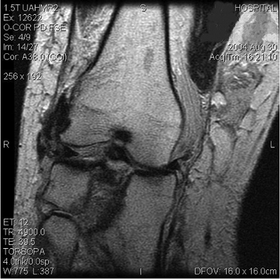
include MRI rather than CT for tibial plateau fractures that occur as a
result of a high-energy mechanism of injury (Fig. 27.3).
We have evaluated 103 patients using MRI following tibial-plateau
fractures at our institution. Numerous soft-tissue injuries of the knee
have been detected, including 25 medial meniscus tears, 35 lateral
meniscus tears, 45 anterior cruciate-ligament tears, 41 posterior
cruciate-ligament tears, 16 posteromedial corner or medial
collateral-ligament tears, and 46 posterolateral corner (PLC) tears.
Seventy-one percent of our patients studied had at least one torn
ligament associated with their tibial plateau fracture. Fifty-five
percent of our patients had two or more ligaments torn, and 26% had
injuries to both the anterior and posterior cruciate ligaments (Fig. 27.4)
or a fracture dislocation of the knee. Published data demonstrate that
between 48% and 90% of patients with tibial plateau fractures have
significant associated soft-tissue injuries of the knee. Our data on
103 patients are similar with an incidence of 71% soft-tissue injuries
involving the knee following tibial plateau fracture. As noted, MRI
scans frequently lead to a change in the treatment plan for patients
following tibial plateau fractures (6–11); therefore, because of the
difficulty in accurately diagnosing knee injuries associated with
tibial plateau fractures, consideration should be given to obtaining an
MRI scan for fractures that result from high-energy trauma.
development of the surgical plan. Complex proximal tibia and tibial
plateau fractures can be very challenging. Depending on the experience
of the surgeon, it may be wise to write a formal surgical plan. Key
factors to consider include the location of surgical incisions as
determined by fracture displacement and
the
condition of the skin, additional instruments (such as the femoral
distractor) needed to assist with reduction, the type of implant to
treat the fracture, and whether bone graft or a synthetic substitute
will be needed.
 |
|
Figure 27.3. MRI scan demonstrating a tibial plateau fracture with a tear of the PLC.
|
 |
|
Figure 27.4. Patient with a positive sag sign indicating a torn posterior cruciate ligament in addition to his tibial-plateau fracture.
|
each with a unique surgical technique. Each system has its benefits and
liabilities, and the surgeon must understand the differences and employ
the locked plate that is most suited for the individual fracture.
locking plates that combine holes allowing standard screws with holes
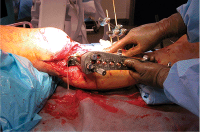
that accept locking screws. The patient should be placed on a
radiolucent operating table in the supine position. A roll of sheets is
placed under the knee, flexing it approximately 25 degrees (Fig. 27.5). The most
commonly employed surgical approach is a midline or an extended,
lateral, parapatellar approach. The length of the incision will be
dictated by the distal extent of the fracture. Great care should be
taken in handling the soft tissues to minimize trauma inflicted by the
surgeon.
 |
|
Figure 27.5. Reduction is improved by placing a roll under the distal femur and thus flexing the knee 20 to 30 degrees.
|
 |
|
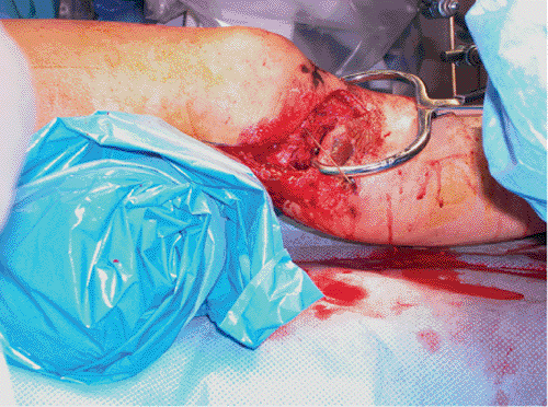
Figure 27.6. Reduction of the condyles using a large tenaculum clamp.
|
reduction of the articular surface. The techniques used are identical
to those used with conventional ORIF. Impacted fragments must be
manually disimpacted, reduced, and stabilized with Kirschner (K) wires
initially and screws definitively. It is critical to evaluate the
fracture for widening of the articular condyles. If the widening is
present, then great care must be taken to reduce them in addition to
reducing the articular surface. The use of a large tenaculum or
articular clamps can be very helpful in reducing the condyles (Fig. 27.6).
We usually use multiple, long, 3.5-mm screws in a subchondral position
to stabilize the articular reduction via the rafting technique. Bone
grafting using autograft, allograft, or synthetics may be necessary
after any impacted fragments have been elevated.
articular portion of the fracture, the locking plate is applied to the
tibia. Most of these plates are designed to be applied to the lateral
side of the tibia. If the fracture pattern requires a medial-based
plate, a plate designed for lateral application on the left tibia will
often fit surprisingly well on the medial side of the right tibia. The
plate is pinned or clamped to the bone and then affixed to the proximal
segment. Both conventional nonlocking screws and locking screws can be
used.
The surgeon should be familiar with these rules prior to attempting
osteosynthesis with a locked plating system. Conventional screws can be
used to reduce the proximal fragment to the plate as well as to lag
fragments together (such as a butterfly does) proximally. After initial
stabilization
of the proximal fragment to the plate, the tibia distal to the fracture
is reduced and stabilized to the plate using temporary wires or
conventional screws. Again, screws are placed using the rules for screw
placement with locking plates.
|
Table 27.1. Rules for Screw Placement in Locked Plating
|
||||||||||||||||
|---|---|---|---|---|---|---|---|---|---|---|---|---|---|---|---|---|
|
carefully assesses the quality of reduction in all planes. If the
reduction is satisfactory, locking screws are placed proximally and
distally to increase the stability of the construct.
the system that is being used. Most of the systems use drill guides
that thread into the threaded plate holes. The drill is used to drill
both cortices, and then the locking screws are initially implanted by
power with the last few turns made via a manual screwdriver. Absolute
data are not available regarding the number and combination of screws
that are required for stability using locked plating systems. A minimum
of four or five screws should be placed proximally and distally.
Paoli, PA) for internal fixation is unique among locking plate systems
because it combines locked plating with a minimally invasive surgical
approach. Use of the LISS internal fixator requires a different
technique than does conventional plate osteosynthesis. It is critical
for the surgeon to remember that the screws will not pull the bone to
the implant, and therefore the fixator cannot normally be used as a
reduction tool. The pull reduction instrument (commonly referred to as
the “whirlybird”) has been developed to allow the bone to be pulled to
the plate prior to placement of locking screws. No screws should be
placed through the fixator prior to restoring length and reduction in
the sagittal and coronal planes. After the surgeon has begun placing
fixed-angle screws, additional reduction will not be possible.
radiolucent operating table. A roll of sheets is placed under the knee
to relax the gastrocnemius muscles and assist in the reduction.
Generally, a roll that places the knee in approximately 25 to 30
degrees of flexion provides the maximum benefit. However, I recommend
evaluating the impact of ligamentotaxis and varying the size and
location of the roll to assess the impact on the reduction of the
fracture. This process of “learning” the fracture prior to placing the
plate can improve the final reduction and save significant time when
the implant has been placed in the submuscular plane.
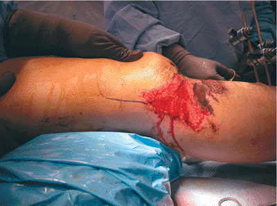
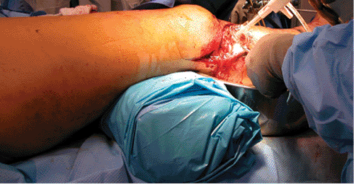
lateral parapatellar or a hockey stick incision. The hockey stick
approach (Fig. 27.7) allows posterior and
proximal extension if the patient has sustained a tear of the PLC of
the knee that requires surgical reconstruction (Fig. 27.8).
A relatively small incision is all that is required for implanting the
LISS fixator. The articular component of the fracture requires
reduction and stabilization
through
techniques that are identical to those used with conventional plating.
It is critical for the surgeon to plan the location of any screws
utilized to stabilize the articular reduction, while keeping in mind
the location of the LISS fixator and screws. One disadvantage of
locking screws is that the surgeon cannot vary the angle of
implantation in order to avoid other screws. Initially, the articular
reduction is stabilized with K wires (Fig. 27.9).
 |
|
Figure 27.7. Extended hockey stick approach.
|
 |
|
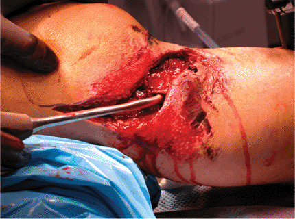
Figure 27.8. Reconstruction of the PLC after ORIF of the tibial plateau.
|
usually complete fixation of the articular component using a rafting
technique with a few 3.5-mm screws. When a satisfactory reduction of
the articular surface has been achieved, electrocautery is used to
release part of the origin of the anterior compartment muscles to
expose the submuscular plane. The submuscular plane is then developed
using either a large periosteal elevator or the end of the LISS plate.
The submuscular plane is usually not difficult to develop.
An important tip is to keep a finger along the anterior crest of the
tibia and feel the tip of the fixator pass distally. This allows a
clear understanding of the tibial plate position in the sagittal plane.
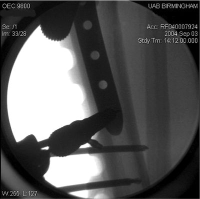
The implant must be located in the middle of the diaphysis of the
distal tibia. If the LISS fixator is not kept in the middle of the
diaphysis, the unicortical screws will not have sufficient pull-out
strength. The plate should be slid slightly farther distally than the
anticipated final position, and then slid back proximally to achieve
the best fit to the osseous contour of the proximal tibia (Fig. 27.11).
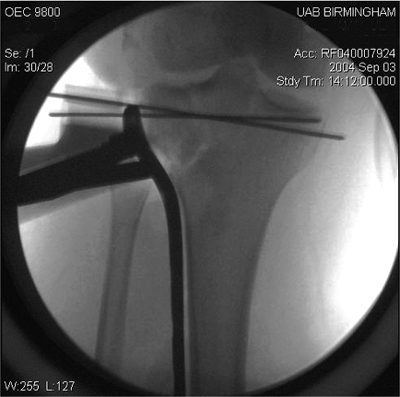
a threaded wire is utilized to pin the internal fixator to the proximal
tibia. Longitudinal traction is then used to obtain length and
reduction in the sagittal plane. The time spent learning the
appropriate reduction maneuver while learning the fracture at the
beginning of the case remarkably eases the process of obtaining a good
reduction. A distal skin incision, correlating with the location of the
distal hole on the plate, is made. The insertion sleeve and trocar are
placed and then the handle is connected to the distal hole on the plate
by a threaded stabilization bolt. Another threaded wire is then
utilized to pin the LISS fixator to the midlateral portion of the
tibial diaphysis.
If it is not located in the middle of the tibial diaphysis, the
threaded wire should be removed and the location of the plate adjusted
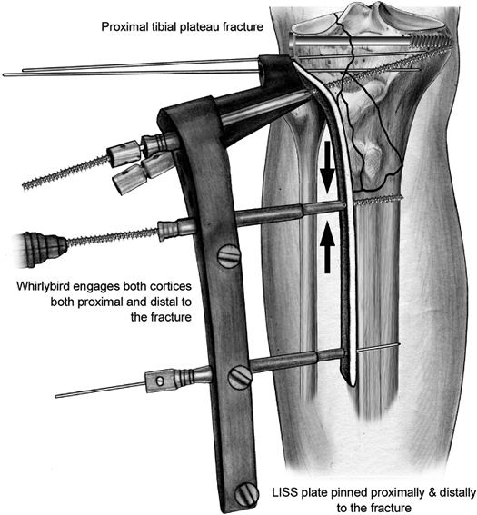
appropriately. An ideal LISS construct involves placing two bicortical
whirlybirds, one just proximal and one just distal to the metaphyseal
or diaphyseal component of the fracture (Fig. 27.13). Some fractures will only require one whirlybird. The whirlybird is placed
through a stab incision corresponding to the desired hole on the
internal fixator, followed by blunt spreading and placement of the
drill guide and trocar. The whirlybird is then drilled into the tibia
while the irrigation system is used and then tightened to stabilize and
reduce any varus mal-alignment of the fracture.
 |
|
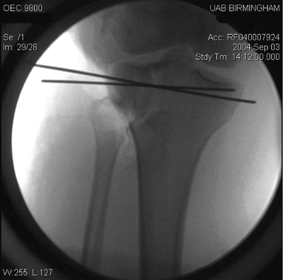
Figure 27.9. Initial stabilization of tibial plateau fracture using K wires.
|
 |
|
Figure 27.10. Sliding the LISS into place using the aiming handle.
|
 |
|
Figure 27.11. Sliding LISS plate back proximally to obtain the best possible fit.
|
 |
|
Figure 27.12. Confirming location of the plate in the midlateral plane of the tibia via fluoroscopy.
|
 |
|
Figure 27.13.
Ideal construct with the LISS plate pinned proximally and distally and a whirlybird placed just proximal and distal to the fracture. |
reduction is obtained and the plate is pinned in place with threaded
wires proximally and distally and stabilized near the fracture with
whirlybirds as needed. The LISS fixator does not have a perfect fit
with the proximal tibia in most individuals due to the anatomic
variability between patients. Because the locked screws do not pull the
fixator to the bone, this can lead to a prominent plate and associated
hardware-related pain. An important surgical tip to help reduce this
possibility should be employed at this point in the case. Prior to
placing the proximal screws, a large reduction forceps should be placed
through a stab incision medially and also attached to the small wire
hole in the proximal anterior portion of the plate. The forceps is
tightened to snug the plate against the tibia prior to the placement of
the proximal screws, minimizing the problem of prominent hardware. As
soon as one or two locking screws have been placed, the forceps should
be removed.
fixator involves placing the locked screws. The C, D, and E holes
should be used with the vast majority of fracture patterns. These
screws provide excellent fixation with divergence from one another in
three dimensions. A drill guide and cannulated trocar are placed in the
E hole (Fig. 27.14). A guide wire is then
drilled through the trocar to the desired position for the screw tip.
The length of the screw is measured using the depth gauge provided, and
the wire and cannulated trocar are then removed. A LISS screw is then
drilled into the proximal tibia while irrigation is used. Power
drilling should be discontinued just prior to the screw head locking
into the holes of the internal fixator. The screw should be locked into
the LISS fixator using the torque screwdriver, tightening it until two
clicks are heard. If power is used to drive the screw all the way into
the locked position, the surgeon runs the risk of creating a cold weld
with the screw, which makes removal extremely difficult if not
impossible. This procedure is repeated for the D and C screws (Fig. 27.15).
posteriorly. Because the screws are powered in and are threaded, it may
be difficult to feel if the posterior cortex is perforated. This screw
should be placed with the knee flexed to keep the popliteal vessels
away from the posterior tibial cortex. The length of the D screw should
be adjusted if necessary after a lateral fluoroscopic view is obtained
and the location of the D screw is carefully scrutinized (Fig. 27.16).
The significance of this screw is easily remembered if the surgeon
realizes that “D is for danger” (to the popliteal vessels). Paying
attention to this small technique point allows consistent safe
placement of this important screw. A fourth screw placed proximally
usually
replaces the proximal whirlybird. Additional screws should be placed
based on the fracture pattern and surgeon’s judgment. A minimum of four
screws should be placed proximally as well as distally.
 |
|
Figure 27.14. Drill guide placed in the E hole.
|
 |
|
Figure 27.15. Guide wire placed into the C hole to allow measurement of screw length.
|
 |
|
Figure 27.16. Lateral fluoroscopy view to allow assessment of D screw location.
|
 |
|
Figure 27.17. Placing screw through the fourth hole by use of the power screwdriver and the irrigation system.
|
locking screws. The technique is similar to that used for the proximal
screws, except that the distal screws are not measured. These screws
are either 18- or 26-mm long. Important technique points include using
irrigation, finalizing placement using a screwdriver, and placing at
least four screws distally (Fig. 27.17). As
noted previously, the plate should be in the midlateral plane of the
bone to avoid transcortical screw placement. I recommend placing two
screws near the fracture site and two screws near the distal end of the
plate for maximum stability (Fig. 27.18).
 |
|
Figure 27.18. AP view showing three of four distal screws in place. The final screw will replace the distal wire.
|
 |
|
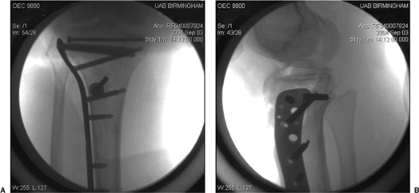
Figure 27.19. A,B. Final fixation of fracture using LISS.
|
those involved with placing pins for external fixators. The ideal
construct is two screws near the fracture sight and two near the end of
the plate (Fig. 27.19). Another important point
for the surgeon to remember is that the risk of damage to neurovascular
structures increases with more distally placed screws. If the 13-hole
plate is being used, great care should be used to spread down bluntly
to the bone and place the trocar system for holes 11–13 (12).
Alternatively, a small incision may be used to expose directly the
distal three holes on the long LISS plate (13).
data available to date. Most of the published data relates to the LISS,
which was the first commercially available, locked-plating system.
Three recently published papers provided results on a total of 149
complex tibial-plateau fractures. Two of the papers reported no
problems with loss of articular reduction or alignment (14,15), and the
third reported 97% stable fixation in the fractures studied (16). These
clinical results substantiate the expected improved stability as a
result of the fixed angles formed by the locked screws. A recent
biomechanical study demonstrated that there was no difference between a
laterally based LISS plate and ORIF with two conventional compression
plates (17). The three clinical studies also reported only two deep
infections, an incidence of only 1.3%. These results are far better
than previously published reports on conventional ORIF of tibial
plateau fractures.
terms of final knee motion and rate of union. Hardware-related pain
near the knee joint appears to be one relatively minor problem with the
LISS (14–16). It is not clear from the data available whether these
early and impressive results are due to the locked plating or to the
minimally invasive surgical approach. It is probable that the low
infection rate is at least partially related to the minimally invasive
surgical approach. The relative contribution of each of these factors
will be clarified as additional publications offer results from using
locked plating through a conventional open approach. Although the early
results using LISS are extraordinarily encouraging, the technique can
be challenging and the surgeon can expect to experience a learning
curve before mastering minimally invasive locked plating.
|
Table 27.2. Complications Associated with Locked Plating Combined with a Minimally Invasive Surgical Approach
|
||||||||||||||||||||||
|---|---|---|---|---|---|---|---|---|---|---|---|---|---|---|---|---|---|---|---|---|---|---|
|
postoperative management from the sparse published literature regarding
locked plating. Our protocol is to begin early knee motion on the first
postoperative day if the soft-tissue injuries will allow. The patient
is placed in a continuous passive motion (CPM) machine with an initial
range of motion of 0 to 10 degrees. Knee motion is increased by
approximately 10 degrees per day as tolerated by the patient. Advancing
motion at a rate faster than 10 degrees per day can lead to wound
dehiscence and is best avoided. We delay the knee motion for
approximately a week if necessary to allow soft-tissue inflammation to
subside.
bearing only. We advance to 50% weightbearing as soon as callus is
appreciated on radiographs. Callus is usually noted between 4 and 6
weeks following surgical stabilization. Patients are generally advanced
to 75% weightbearing after an additional 3 weeks and to full weight
bearing by 11 to 12 weeks following surgery. Resistance exercises,
athletic activities, and heavy work are avoided until 4 to 6 months
following locked plating.
very similar to those associated with ORIF with conventional
compression plates. Infection, wound dehiscence, knee instability, loss
of knee motion, hardware failure, nonunion, malunion, and
hardware-related pain have all been reported. Table 27.2
documents the combined incidence of complications from the three
recently published clinical series in which locked plating with a
minimally invasive surgical approach was used (14–16). Although the
authors reported a variety of complications, the number of incidences
is remarkably lower than reports for either conventional ORIF or for
stabilization with small-wire external fixators.
with an exceptionally high risk of complications. The early results for
locked plating combined with a minimally invasive surgical approach are
very encouraging. There is not sufficient published data to determine
the complication rate for locked plating using conventional surgical
approaches.
SV, Nevins RT, Sallis JG, et al. Impact of MRI on treatment plan and
fracture classification of tibial plateau fractures. J Orthop Trauma 2002;16(9):632–637.
L, Abdollahi K, Lee J, et al. The prevalence of soft tissue injuries in
nonoperative tibial plateau fractures as determined by magnetic
resonance imaging. J Orthop Trauma 2002;16(9):628–631.
JP, DeAngelis NA, Anderson R. Anatomy of the superficial peroneal nerve
in relation to fixation of tibia fractures with the Less Invasive
Stabilization System. J Orthop Trauma 2004;18(8):536–539.
PJ, Stannard JP, Cole PA, et al. Prospective clinical trial of the Less
Invasive Stabilization (L.I.S.S.) for supracondylar femur fractures. J Orthop Trauma 2000;14(2):133–134.
WM, Rudzki JR, Borrelli J Jr. Treatment of complex proximal tibia
fractures with the Less Invasive Skeletal Stabilization System. J Orthop Trauma 2004;18(8):521–527.
JP, Wilson TC, Volgas DA, et al. The Less Invasive Stabilization System
in the treatment of complex fractures of the tibial plateau: short-term
results. J Orthop Trauma 2004;18(8):552–558.
PA, Zlowodzki M, Kregor PJ. Treatment of proximal tibia fractures using
the Less Invasive Stabilization System: surgical experience and early
clinical results in 77 fractures. J Orthop Trauma 2004;18(8):528–535.
T, Schandelmaier P, Marti A, et al. Less invasive stabilization of
complex tibial plateau fractures: a biomechanical evaluation of a
unilateral locked screw plate and double plating. J Orthop Trauma 2004;18(8):546–551.