
vertebral motion segments that have become unstable and/or painful
because of a variety of conditions (degenerative disc disease; trauma;
and isthmic or degenerative spondylolisthesis, among others). All
fusion surgery involves bone graft to provoke a biologic response and
cause the graft to fuse with the vertebral elements, thereby stopping
motion between vertebrae at the affected level(s). Optimally, spinal
fusion for the reduction of pain involves one or more motion segments;
however, fusing more segments excessively reduces the normal spinal
movement and may place too much stress on adjacent vertebral joints. In
recent decades, the introduction of spinal instrumentation has enhanced
the rate of successful fusion, in part because of the added stability
that they provide at the fusion site during healing.
under physiologic loads to maintain normal relationships between
vertebrae, in such a way that there is neither damage nor subsequent
irritation to the spinal cord or nerve roots. Many authors have
attempted to define instability. Frymoyer presented a clinical
definition stating “a loss of spinal motion segment stiffness, such
that force application to that motion segment produces greater
displacement(s) than would be seen in a normal structure, resulting in
a painful condition, and placing neurologic structures at risk.” This
is a fairly thorough clinical description of instability. The term
segmental instability, coined by McNab, has been used to describe
greater than normal angulatory and translatory motion as a result of
degenerative disc disease. Through cadaveric studies, White and Panjabi
have attempted to quantify instability and as a result have developed
radiographic criteria for instability. Using flexion and extension
radiographs, translational motion of 3.5 mm or angular motion of 11
degrees of one vertebra over another is indicative of segmental
instability.
posterolateral intertransverse fusion, posterior lumbar interbody
fusion (PLIF), anterior lumbar interbody fusion (ALIF), and
anterior/posterior spinal fusion. This chapter is limited to discussion
of posterior approaches, most particularly the gold standard of spinal
fusion, posterolateral intertransverse process fusion (using
transpedicular screw instrumentation and posterior iliac crest bone
grafting).
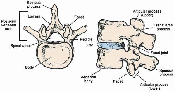
structures of the posterior lumbar spine is important for performing a
safe and successful spinal fusion. Posterior bony elements of a lumbar
vertebra include the spinous process, laminae, pars interarticularis,
facets, transverse processes, and pedicles (Fig. 19-1).
Posterior soft tissue structures include the supraspinous ligament,
interspinous ligament, ligamentum flavum, and facet capsules. The
pedicles are cylindrical bony projections off the posterosuperolateral
aspect of the vertebral body that connect the vertebral body with the
posterior bony arch. The pedicles are oriented in an anteromedial
direction when viewed from the posterior. This angulation progressively
increases from L1 through L5. Also, the cylindrical diameter of the
pedicles progressively increases from the upper to the lower lumbar
spine. This knowledge of pedicle anatomy is extremely vital for safe
and successful insertion of screws into the pedicle. The spinous
process of each vertebra extends caudally and overlaps the vertebra
below by about one half of a segment. For example, the tip of the
spinous process of L4 is actually over the body of L5.
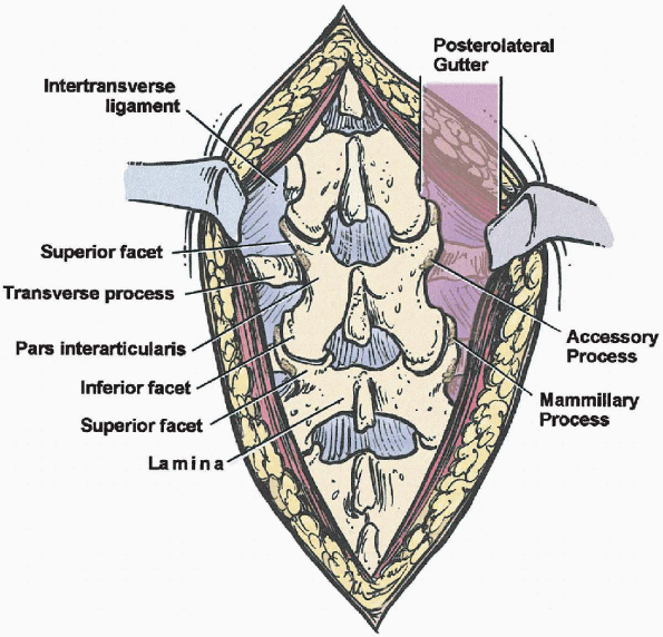
which project laterally both cranially and caudally, to form the
superior and inferior facets, respectively (Fig. 19-2).
The portion of bone found between the superior and inferior facets is
the pars interarticularis and is named for its location between the
articular processes. The lateral most part of the pars interarticularis
is C-shaped and easily found between the facet joints (Fig. 19-2).
It is important to identify the lateral border of the pars
interarticularis. Excessive bone removal during laminectomy
decompression can lead to destabilization of the vertebra. Once the
pars interarticularis is found, the C-shaped lateral border can be
followed superiorly to the inferior edge of the transverse process and
the accessory process (on the posteroinferior aspect of the root of the
transverse process) is found. These are important landmarks for pedicle
screw insertion, which is discussed later. The superior articular
process is found adjacent to the transverse process and accessory
process and is directly over the pedicle (Fig. 19-2).
The convergence of these three structures is important in the
identification of the pedicle. The accessory process and mammillary
process (rough elevation on posterior border of superior facet ) may be
difficult to locate and can be absent in some patients. The superior
articular process is oriented in an anterolateral position relative to
the inferior articular process of the cephalad vertebra. For example,
when examining the L4-5 facet joint the superior facet of L5 is found
anterior and lateral to the inferior facet of L4.
fusion (Fig. 19-2).
The gutter is generally defined as the area lateral to the facet
joints, supported anteriorly by the transverse processes and the
intertransverse ligament.
 |
|
FIGURE 19-1. Anatomy of lumbar vertebrae.
|
 |
|
FIGURE 19-2. Posterior spinal elements.
|
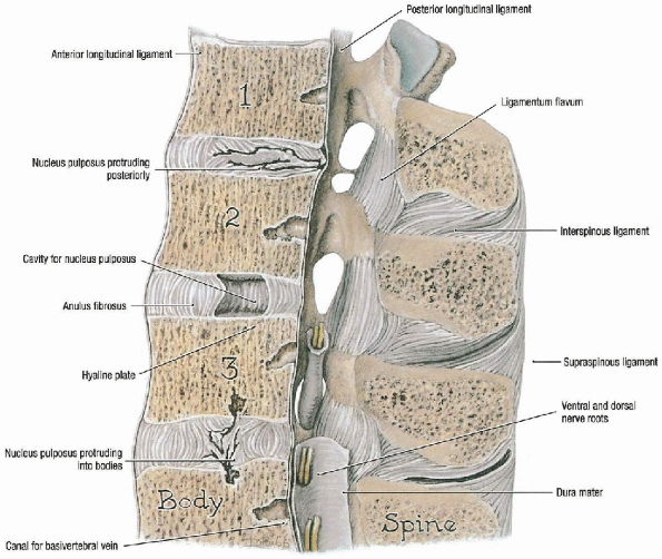
include the supraspinous ligament, which runs along the dorsal aspect
of the spinous processes, and the interspinous ligament, which
segmentally attaches between spinous processes (Fig. 19-3).
These two ligaments aid in resisting flexion moments. The ligamentum
flavum is a strong, elastic structure that runs in a shingle pattern.
It originates on the ventral surface of the cephalad lamina and inserts
onto the dorsal surface of the caudal lamina.
layers. The latissimus dorsi is the most superficial muscle and is
covered centrally by the lumbodorsal fascia. The deep muscle layer is
subdivided into the superficial layer and deep layer, which contain the
transversocostal group and the transversospinal group, respectively.
The transversocostal group consists of the iliocostalis, the
longissimus, and the spinalis muscles forming the erector spinae group.
The transversospinalis group consists of the short rotators:
multifidus, rotatores, interspinalis, and intertransversarii.
 |
|
FIGURE 19-3. Ligaments of lumbar spine. (From Agur AMR, Lee MJ. Grant’s atlas of anatomy, 10th ed. Philadelphia: Lippincott Williams & Wilkins, 1999, with permission.)
|
disorders of the lumbar spine is still not fully defined. Agreement
concerning specific indications for spinal fusion
has
evolved slowly. Posterior spinal fusion is commonly used to stabilize
lumbar motion segments in spinal stenosis, degenerative
spondylolisthesis, isthmic spondylolisthesis, recurrent disc
herniation, scoliosis (degenerative or idiopathic), kyphosis, and back
pain.
 |
|
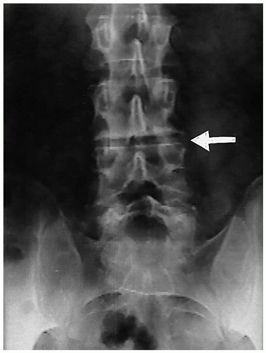
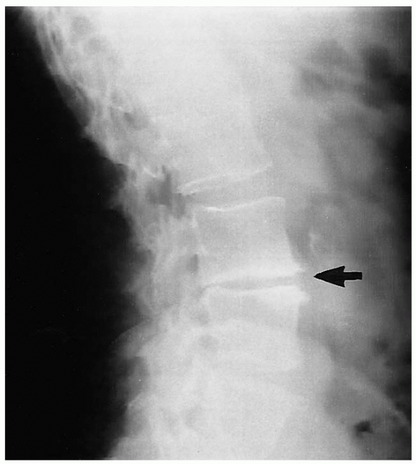
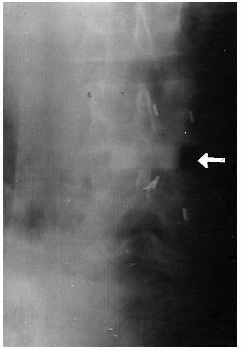
FIGURE 19-4. Preoperative anteroposterior x-ray film. L3-4 disc space collapse (arrow).
|
back pain. Spinal pain can originate from mechanical, inflammatory, or
neurochemical sources. The exact mechanisms are not clearly understood,
but vertebral motion plays an important role. The purpose of spinal
fusion is to eliminate pathologic motion and thereby eliminate pain. In
cases of deformity, the goal of spinal fusion is to maintain correction
and prevent progression of deformity.
particularly with the addition of instrumentation. Therefore, the
benefits to be obtained must be weighed against the risks. The primary
indications for use of instrumentation in lumbar spinal fusions are
segmental instability, deformity correction, unstable spinal trauma,
and improvement in the healing rate of the fusion. This last indication
is particularly important in repeat fusions in cases of
pseudoarthrosis. Added risks associated with the use of instrumentation
include increased blood loss, possible iatrogenic neural injury, and a
higher postoperative wound infection rate.
 |
|
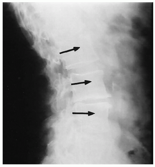
FIGURE 19-5. Preoperative lateral x-ray film. L3-4 disc space collapse (arrow).
|
 |
|
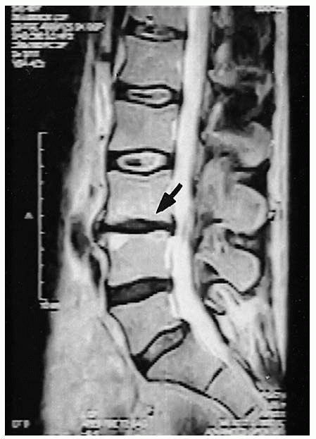
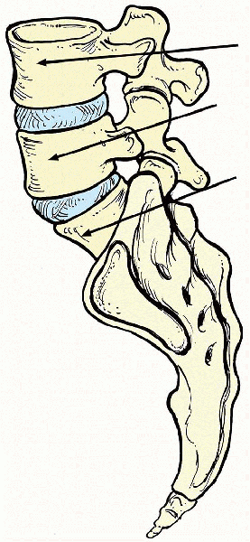
FIGURE 19-6. Preoperative T2-weighted sagittal magnetic resonance imaging. At L3-4, note decreased disc height (arrow), decreased signal, and endplate changes.
|
confirm the correct vertebral level or levels of fusion and to localize
the incision. Anteroposterior (AP) and lateral radiographs (Figs. 19-4 and 19-5), as well as axial computerized tomography (CT) or magnetic resonance imaging (MRI) (Figs. 19-6 and 19-7)
are used for the purpose of identifying the injured vertebra or
vertebrae and to estimate the position, orientation, and width of the
vertebral pedicle; the latter pedicle information is important for
later instrumentation
of
the vertebrae. There are several techniques for localization of the
incision and these are discussed within the section on patient position
and preparation section.
 |
|
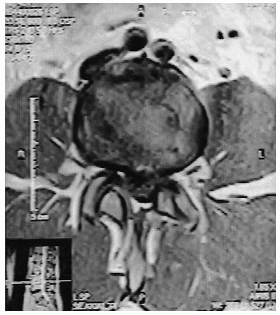
FIGURE 19-7. Preoperative T1-weighted axial magnetic resonance imaging. L3-4 central disc bulge.
|
 |
|
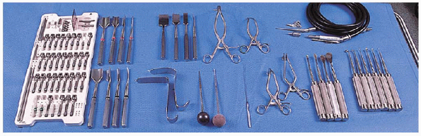
FIGURE 19-8. Equipment. (left to right): transpedicular implant system (pedicle screw system), gouges (autograft procedure); (top row) curved osteotomes (autograft procedure), two Gelpi retractors, high-speed burr; (bottom row)
Taylor retractors, straight and curved blunt-tipped pedicle finders, flexible ball-tipped probe, two cerebellar retractors, Cobb elevators, and curettes. |
-
Frame choices:
-
Andrews frame/kneeling
-
Jackson table/hip extension
-
Four-post Relton-Hall frame/hip extension
-
-
Cerebellar retractors
-
Cobb elevators
-
Curved osteotome (autograft procedure)
-
Curettes and gouges (autograft procedure)
-
Gelpi retractors
-
Taylor retractor
-
Radiopaque marker pins
-
High-speed burr or awl
-
Straight or curved blunt-tipped pedicle finder
-
Flexible ball-tipped probe
-
Transpedicular implant system (pedicle screw system)
-
Bone wax
-
Gelfoam
 |
|
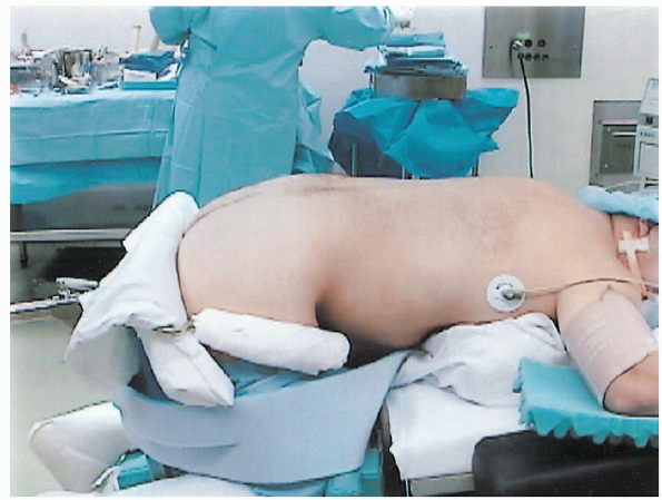
FIGURE 19-9. Knee-chest patient position using Andrews kneeling frame.
|
important for several reasons. First, adequate relief of intraabdominal
pressure reduces epidural venous pressure and decrease intraoperative
bleeding. Second, several positioning frames exist that allow for
varying amounts of lumbar lordosis. Each type of frame has advantages
and disadvantages. Kneeling frames, such as the Andrews frame, flex the
hips and reduce lumbar lordosis (Fig. 19-9).
This has the effect of opening the interlaminar space and thus may
facilitate decompression of the spinal canal. However, the reduced
lumbar lordosis may be undesirable if an instrumented lumbar fusion is
being performed. Frames that allow for full hip extension, such as the
Jackson table or the four-post Relton-Hall frame, allow for full lumbar
lordosis and subsequently narrow the interlaminar space. This may make
central canal and lateral recess decompression more difficult and also
presents a “worst case scenario” to ensure an adequate decompression. Caution
must always be taken when positioning a patient on any prone
positioning frame because injury to the skin overlying bony prominences
is more likely if not thoroughly padded. In addition, abduction of the
arms should be limited to 90 degrees to the trunk axis to avoid a
possible stretch injury to the brachial plexus.
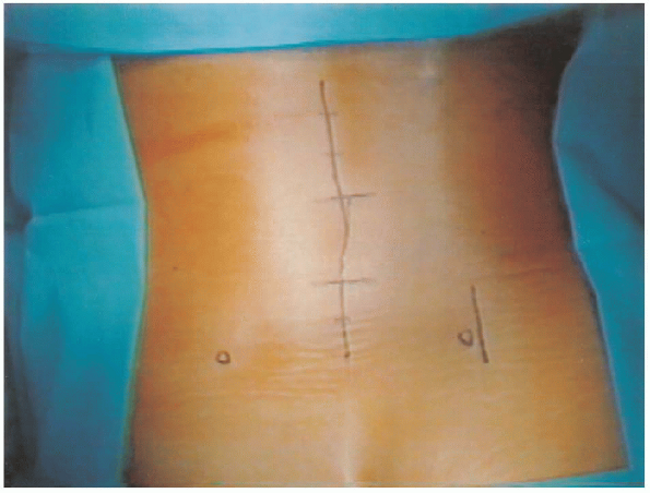
one obtain a rough approximation of the operative level in the lumbar
spine (Fig. 19-10). The top of the iliac crests generally
are seen at the L4-5 level on lateral radiograph. With palpation of the
top of the crests, the thumbs can be brought to the midline at the
crest level and the L4 spinous process is generally found.
Alternatively, the sacrum may be palpated over the midline in a
cephalad direction. The first notable prominence is the L5 spinous
process. It is reiterated that these landmarks are approximations only
and it is our recommendation that an intraoperative cross-table lateral
radiograph with markers be obtained to establish the correct level of
the operation.
 |
|
FIGURE 19-10.
Surgical markings for midline posterior lumbar incision and a separate iliac crest incision. Left and right circles mark each posterior superior iliac spine. |
using sterile technique can be useful for localization of the incision.
For a lumbar discectomy, an 18-gauge needle is placed along the
superior aspect of the spinous process of the cephalad vertebra. This
usually corresponds to the superior pole of the incision for
approaching the operative disc level. For example, the needle placement
for an L4-5 lumbar discectomy would be along the superior aspect of the
L4 spinous process. A second lateral radiograph is obtained for level
confirmation following exposure and before decompression.
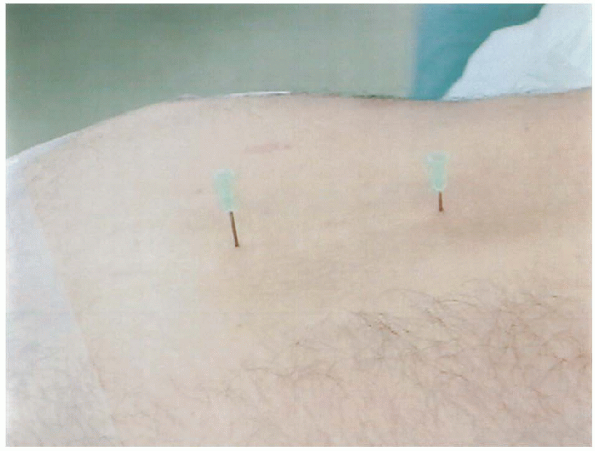
cross-table lateral radiograph with two 18-gauge needles positioned to
mark the superior and inferior poles of the incision before sterile
preparation (Fig. 19-11). This is generally
along the spinous processes two levels above the cephalad vertebra and
one level below the caudal vertebra to be fused. Once the exposure is
completed, a second intraoperative lateral radiograph is taken with a
straight clamp placed on an interlaminar area. Alternatively, an
18-gauge spinal needle can be placed into the exposed mamillary
processes. This aids in identifying the insertion point and direction
for pedicle screw placement if instrumentation will be used. Generally,
we always try to obtain as much information as possible from
intraoperative radiographs.
 |
|
FIGURE 19-11.
Localization of incision. Placement of two 18-gauge needles at superior and inferior poles of incision, followed by cross-table lateral radiograph. |
This midline skin incision can be followed by one of two different
fascial exposures: a direct posterior approach and an intermuscular
posterolateral approach to the lateral facets, transverse processes,
and intertransverse space. The posterior approach, the workhorse of the
lumbar spine, is the subject of this chapter. It provides access to all
of the posterior spinal elements by means of a single longitudinal
midline fascial incision. Direct exposure of the spinous process,
laminae, and facets at all levels can be achieved. In addition, further
lateral dissection and retraction of the paraspinal musculature can
also reach the transverse processes and posterolateral gutter. If
necessary, exposure of the posterior wall of the vertebral body and
disc space can be achieved following laminotomy or laminectomy. This
requires mobilization and medial retraction of the thecal sac or a more
lateral exposure of the disc space, either via the neural foramen or
more laterally (extraforaminal). The conus medullaris in the upper
lumbar segments prevents safe medial retraction of the thecal sac.
Dissection proceeds through subcutaneous adipose tissue either sharply
or with electrocautery to the lumbodorsal fascia. Cerebellar retractors
placed in the subcutaneous tissue allow tension to be applied to the
tissues and expedite dissection. Meticulous hemostasis is imperative.
To facilitate closure and to ensure midline dissection, a Cobb elevator
can be used to gently clear adipose tissue from the midline, thereby
clearly exposing the midline fascia. The lumbodorsal fascia is then
incised with electrocautery over the bulbous tip of the
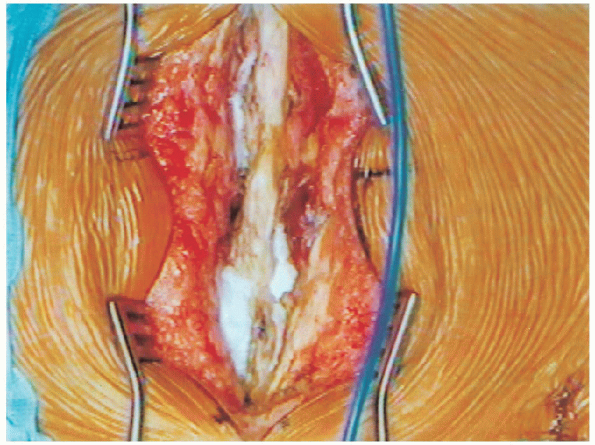
spinous process (Fig. 19-13). This is carried out through all the spinous processes to be removed. We
recommend leaving intact the midline fascia and supraspinous ligament
of the spinous processes that are not part of the planned
decompression. This allows for stability of the posterior column of the
remaining vertebrae and also provides a midline structure for
reattachment of the fascia during wound closure. Once the fascia
is incised, the musculature is elevated subperiosteally along the
lamina with electrocautery. This is best done in a caudal to cephalad
direction, because the paraspinous muscles originate obliquely on the
midline interspinous ligament. Packing sponges helps facilitate the
dissection and also aids in hemostasis. 
Sponges are removed and cerebellar retractors are placed deeper in the
wound to retract the paraspinal muscles. Next, dissection proceeds
laterally to identify the facet joint capsule. Care must be taken to
avoid disruption of the facet capsule if spinal instrumentation is not
to be used. Once the facets are identified, the pars interarticularis
is exposed between the joints. Identification of
this landmark is crucial during canal decompression, because
overzealous widening of the central canal can lead to violation of the
pars interarticularis and subsequent iatrogenic fracture and
instability. If the surgical plan is to perform a fusion limited
to the posterior spinal structures, then surgical exposure to this
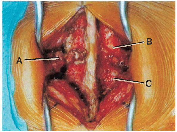
point is generally satisfactory. If a posterolateral fusion is planned,
then further lateral dissection is necessary to expose the transverse
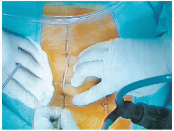
processes and intertransverse spaces (lateral gutters) (Fig. 19-14).
 |
|
FIGURE 19-12. Midline incision through skin.
|
 |
|
FIGURE 19-13. Lumbosacral fascial incision.
|
 |
|
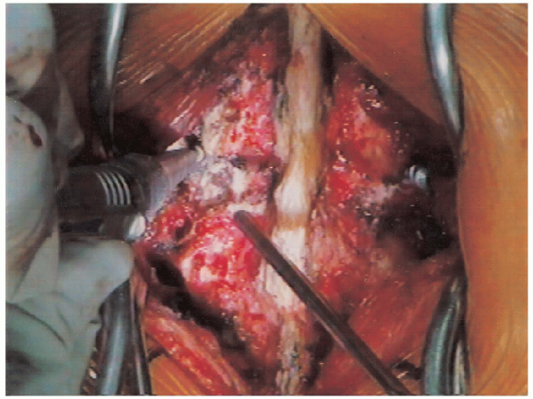
FIGURE 19-14. Deep surgical dissection. A: L3 transverse process. B: L2-3 facet joint. C: L3-4 facet joint.
|
removal of soft tissue overlying the pars using a Cobb elevator to
sweep the muscle laterally away from the pars. Bleeding
is routinely encountered during pars dissection and should be
anticipated. Caution should be used to avoid dissecting anteriorly
around the lateral border of the pars because the dorsal root ganglion
is beneath the pars. Next, dissection of the paraspinal muscles
off the facet capsule is facilitated by gentle retraction of the
muscles with a Cobb elevator up and over the facet joint capsule. The
last obstacle to overcome is exposure of the transverse processes.
These can be palpated laterally at the caudal aspect of each facet
joint. As mentioned earlier, the superior articular process (of the
caudal vertebra) lies anterolateral relative to the inferior articular
process (of the cephalad vertebra) and the transverse process (part of
the caudal vertebra) is adjacent to the superior articular process. Also,
the transverse process can be found by following the lateral border of
the pars superiorly, where an accessory process is often found near the
base of the transverse process. A Cobb elevator is used, along
with electrocautery, to subperiosteally release and laterally sweep
muscle attachments from the transverse processes. Bleeding
is routinely encountered during dissection along the lateral wall of
the superior articular process. The facet bleeder has a predictable
course over the lateral wall of the facet, and the electrocautery can
be held over this position to stop the bleeding. Once the
transverse processes have been identified, gentle retraction with a
Cobb elevator in a lateral sweeping motion allows for exposure of the
intertransverse ligament. This ligament will serve as an anterior sling
along which to span bone graft from one transverse process to another
for achieving an intertransverse process fusion. Caution
must be taken to avoid anterior penetration through this ligament
because the retroperitoneal space, containing nerve roots and vascular
structures, is immediately anterior. Bleeding from anterior to the
intertransverse ligament may be difficult to control, but attempts to
control it should be made with bipolar electrocautery and hemostatic
agents rather than uncontrolled unipolar electrocautery. Once
sufficient lateral exposure is obtained, self-retaining retractors are
placed over the transverse processes at the cephalad and caudal ends of
the exposure, and the lateral gutters are tamponaded with packing
sponges.
fusion refers to a fusion limited to the posterior elements including spinous processes, facets, and laminae. An intertransverse process fusion
(posterolateral fusion) refers to a fusion between the transverse
processes of adjacent vertebrae within the posterolateral gutter,
including the lateral borders of the pars interarticularis and superior
articular facet processes. Fusion levels can also be provisionally
stabilized with the use of metallic internal fixation (spinal
instrumentation).
the posterior spinal structures, excluding the transverse processes and
posterolateral gutters. Once the surgical approach is completed,
preparation for bone grafting and fusion can be initiated. Thorough
denuding of the spinous processes and laminae is performed with
curettes, rongeurs, or a motorized burr. The spinous processes and
laminae can also be split and shingled using a sharp osteotome,
creating additional living, bleeding bone surfaces for healing. Facet
joints involved in the fusion should be denuded of their capsule and
articular cartilage. Once decortication is completed, local and
harvested iliac crest bone graft is placed along the interlaminar
spaces to bridge the laminae. Caution must be used to avoid having bone
graft in communication with a lamina not involved in the planned
fusion. Cancellous bone chips are packed into the decorticated facet
joints. Once bone grafting is completed, the muscle and fascial layers
are approximated tightly with absorbable suture, often over a deep
self-suction surgical drain. The subcutaneous layers are well
approximated to avoid dead space, and the skin is closed.
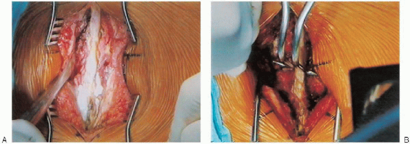
gutters requires strategic placement of deep retractors. Cobb elevators
are placed bilaterally directly on the posterior surface of the most
cephalad transverse processes to sweep the deep tissues laterally (Fig. 19-15A).
While retracting these tissues, the blades of the deep self-retaining
retractor (we use a Gelpitype retractor to avoid excessive tissue
pressure) are placed along the transverse processes; simultaneously,
the elevators are gently brought out posteriorly as the self-retaining
retractor is engaged and spread. The same technique is repeated over
the caudal transverse process so that a Gelpi retractor is placed at
both ends of the wound (Fig. 19-15B). It should
be noted that the use of different types of retractors for deep
exposure may require the use of different techniques to apply the
retractor and complete the exposure.
 |
|
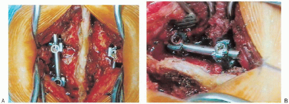
FIGURE 19-15. A: Cobb elevator is used to sweep deep tissues laterally off of the transverse processes. B: Gelpi retractors.
|
ensure thorough soft tissue debridement from the transverse processes,
the facet joint, and the pars interarticularis. Decortication of these
structures is performed with a high-speed burr. The facet joints
involved in the fusion are also denuded of cartilage and decorticated
using the burr. Local bone graft (spinous process, laminar fragments),
if available, and harvested iliac crest bone graft is placed over the
intertransverse ligament to bridge the transverse processes. Cancellous
bone is also placed into the facet joints and packed with a bone tamp
and mallet. Once bone grafting is completed, the routine closure
proceeds as previously described previously.
scaffold of osteoconductive and possibly osteoinductive material to
accelerate or augment the normal healing process of bone. Autologous
bone graft has an osteoinductive capacity not found in allograft bone
and provides for a significantly higher rate of successful bone fusion.
However, harvesting autologous bone can add significant morbidity to a
spinal fusion.
iliac crest bone, generally harvested from posterior iliac crest, and
local bone graft obtained from the surgical site (spinous process and
laminae).
subcutaneous dissection of the inferior aspect of the primary surgical
incision or through a separate incision centered over the posterior
superior iliac spine (PSIS). There are advantages and disadvantages to
either approach. Performing a subcutaneous dissection through the
primary surgical incision obviates the need for an additional incision.
However, hematoma formation from the iliac crest can result in wound
complications that would affect both the primary surgical site and the
iliac crest site. Also, a secure closure of the dissected fascia
overlying the iliac crest may be more difficult to achieve through this
approach. Alternatively, using a second skin incision over the iliac
crest avoids the previously mentioned complication. Although a second
surgical incision leaves the patient with two surgical scars, the
benefit obtained from a separate iliac crest incision may outweigh
cosmetic results.
separate parasagittal incision or through an extension of the operative
midline incision. For a parasagittal incision, a longitudinal line,
approximately 6 to 8 cm in length, is drawn centered just lateral to
the PSIS (Fig. 19-10). Two thirds of the incision should be above the PSIS. Placement
of the incision further laterally places the cluneal nerves at risk.
Placement directly over the PSIS may make the patient prone to more
postoperative pain from direct pressure, especially for thin patients.
After the skin is incised, electrocautery may be used to continue the
subcutaneous dissection while controlling hemostasis. Alternatively,
the iliac crest can be reached through the same midline skin incision
used for the spinal fusion. This requires further caudal extension of
the incision. With this approach, dissection is carried out laterally
above the fascia toward the PSIS.
either approach, the dissection at this point is the same. Once the
iliac crest is encountered, the electrocautery is used to incise the
fascia along the curvature of the crest (Fig. 19-16).
The gluteus musculature is elevated in a subperiosteal fashion from the
lateral surface of the ilium with the use of a Cobb elevator. A Taylor
retractor is then placed deep into the wound and secured into the
lateral wall of the ilium.
An osteotome is used along the lateral wall of the ilium to score the outer table, creating strips of cortical bone. A curved osteotome is used along the base of the exposure and along the
upper aspect of the lateral wall of the crest, driven between the inner
and outer table to release cortical strips.
Special care should be taken to maintain the posterior cap of the iliac
crest intact unless needed for additional bone. At this point curettes
and/or gouges are used to harvest cancellous bone. Maintaining posterior cap intact minimizes postoperative pain when sitting or laying supine, especially with thin patients.
Thesciatic notch must be avoided during bone graft harvesting; inadvertent
injury to this region can lead to a sciatic nerve injury or a
significant bleeding problem from injury to the superior gluteal artery.
After harvesting of the available cancellous bone, the wound is
irrigated copiously and bone wax or Gelfoam are applied to the bleeding
cancellous surfaces for hemostasis.
The fascial layer is closed with heavy absorbable suture. If necessary, a deep or subcutaneous wound drain can be placed.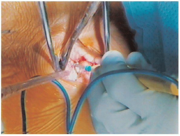 |
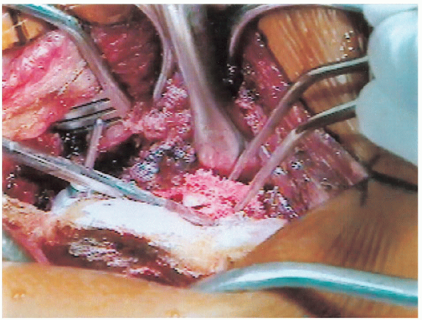
|
FIGURE 19-16. Incising iliac crest fascia with cautery.
|
advancement in spinal implants and the ability to control and stabilize
vertebrae from a posterior approach. Pedicle screws are placed through
the pedicle of lumbar vertebrae from a posterior to anterior direction.
Unlike hooks, secure fixation of the screws does not depend on the
presence of an intact posterior bony arch, making screw fixation the
implants of choice in patients with a previous or concurrent
laminectomy. Pedicle screws provide a great resistance to various loads
because of their bone purchase into the vertebral body. By obtaining
fixation into the anterior column, greater rotational control is
achieved. There are many pedicle screw systems available on the market
today. A list of Food and Drug Administration (FDA) approved pedicle
screw systems is available from the North American Spine Society.
share a similar screw insertion technique. Pedicles screw insertion is
technically demanding, requiring an excellent knowledge of
the
regional anatomy and pathoanatomy of the lumbar spine. Malpositioning
of a screw can result in neurologic injury, violation of a normal
adjacent intervertebral disc space, and failure of fixation. This
description of screw insertion is not meant as a sole source of
instruction for a surgeon; it is an adjunct approach. Pedicle screw
placement should only be attempted by a qualified spinal surgeon
following fellowship training or during a direct apprenticeship.
lateral images may be of significant value to identify the direction of
the pedicles. Oblique imaging can be helpful to follow insertion
directly along the axis of the pedicle. Surgical exposure of the base
of the transverse process is mandatory for pedicle screw insertion.
This can be accomplished using the midline posterior spinal approach
described previously or a paraspinal approach, avoiding muscle
dissection in the midline. The accessory process, pars
interarticularis, and the transverse process are important landmarks
for the screw insertion point that must be visualized (Fig. 19-10).
There are several anatomic relationships that may be helpful in
identifying the location of the pedicle. The use of a lumbar spine
model is instrumental in gaining an appreciation and understanding of
the posterior arch and the pedicular anatomy.
 |
|
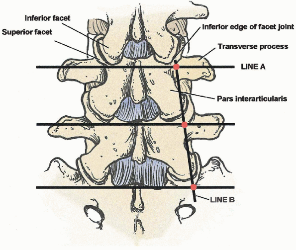
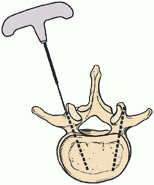
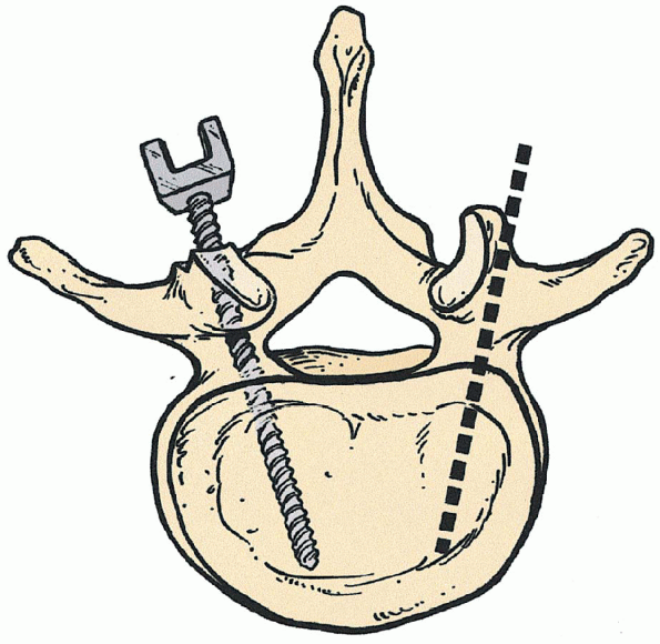
FIGURE 19-17. Starting point for pedicle screw: cross-section of line A bisection of transverse processes and B lateral border of the pars interarticularis.
|
border of the pars intersects with the medial border of the pedicle in
all lumbar pedicles except L5 (Fig. 19-17). At
L5 the opposite is true, a longitudinal line drawn along the lateral
border of the L5 pars intersects with the lateral border of the L5
pedicle. This occurs because there is an increase in the medial
angulation of the central axis of each pedicle as one progresses
through the lumbar spine from L1 to L5. Second, the intersection of a
longitudinal line through the facet joint and a horizontal line (Fig. 19-17)
through the middle of the transverse process marks the location of the
pedicle deep to these structures. Finally, it is generally accepted
that the medial angulation of the pedicle cortical tube progresses by 5
degrees between L1 and S1. For example, medial pedicle angulation at L1
is 5 degrees and L5 is 25 degrees. These anatomic landmarks are meant
to be rough approximations only.
starting point for a pedicle screw is found by bisecting the base of
the transverse process horizontally, proceeding medially up against the
lateral border of the facet joint.
This
usually places the starting point directly over the accessory process
when it is present. Next, a 3-mm ball-tip high-speed burr or awl is
aimed in an anteromedial direction and is used to make a starting hole
along the lateral aspect of the facet (Fig. 19-18).
The orientation of the pedicle in both the transverse and sagittal
planes must be kept in mind at this point. It is necessary to refer to
the intraoperative lateral radiograph to determine the sagittal
orientation of the pedicle (i.e., cephalad, caudal, or perpendicular to
the floor) (Figs. 19-19 and 19-20). A straight or curved blunt-tipped
pedicle-finder is placed into the starting hole and directed
anteromedially in the transverse plane, as indicated by the level, and
also in the sagittal plane, as indicated by the pedicle direction on
the intraoperative lateral radiograph (Figs. 19-21 and 19-22).
The probe is advanced to a depth of approximately 40 to 45 mm only if
it passes with relative ease. If there is uncertainty about the
position of the probe, a marker can be placed into the created hole and
radiographic evaluation is done before continuing (Fig. 19-23).
Next, a flexible ball-tipped probe is placed into the pedicle and all
four walls (superior, inferior, medial, and lateral) are examined for
continuity of bony surface.
Depth of the created screw tract is also assessed, being sure of a bony
deep endpoint. Radiopaque marker pins can be placed into the pedicle
holes and an intraoperative radiograph or fluoroscopic image can be
obtained to confirm intrapedicular positioning of the markers (Fig. 19-24). Following this, the pedicle hole may be tapped, and the screw inserted (Figs. 19-25 and 19-26). Once all screws are inserted, longitudinal rods are connected and a cross-linking bar can be applied as well (Fig. 19-27). Standard wound closure over drains completes the procedure.
 |
|
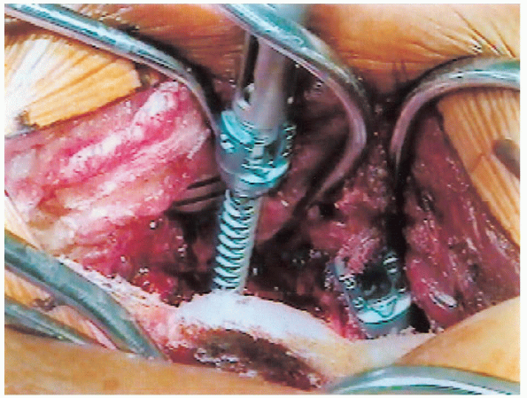
FIGURE 19-18. High-speed burr; decortication of mamillary process exposing entrance to pedicle.
|
 |
|
FIGURE 19-19. Pedicle screws parallel to endplates or with slight superior angulation to penetrate denser bone near endplate.
|
 |
|
FIGURE 19-20.
Preoperative lateral x-ray film. L3-4 disc space collapse (note position of pedicle and orientation for insertion of pedicle screws). |
 |
|
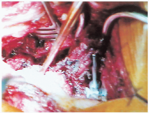
FIGURE 19-21. Probe is at pedicle entrance and angled at correct superior/inferior and medial/lateral orientation to create pedicle track.
|
 |
|
FIGURE 19-22. Pedicle finder in right L3 pedicle.
|
 |
|
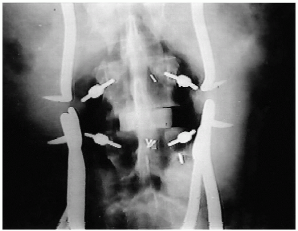
FIGURE 19-23. Intraoperative anteroposterior x-ray film with markers in pedicles of L3 and L4.
|
 |
|
FIGURE 19-24. Radiopaque marker placed into pedicle to assess pedicle orientation.
|
screw fixation is used and posterolateral fusion is being done, it is
recommended to obtain bone graft before placement of the screws. Then,
after preparation of the screw hole, the lateral elements should be
decorticated;
and the bone graft placed in the lateral gutter before final insertion of the screws (Fig. 19-28). After screw insertion, visualization of the lateral gutter and bony
elements may be quite limited, making complete decortication and proper
grafting difficult if not impossible.
diminished signal on the T-2 weighted image indicating disc desiccation (Fig. 19-6).
Plain radiographs, in the anteroposterior and lateral projection, of
this individual demonstrate the loss of disc space height and early
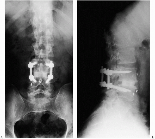
osteophytic changes (Figs. 19-4 and 19-5). Restoration of the disc space height was achieved with an ALIF using a femoral ring allograft as a structural support (Fig. 19-29). Postoperative radiographs demonstrate the final pedicle screw construct for a one level fusion (Fig. 19-30).
 |
|
FIGURE 19-25. Insertion of pedicle screw medially and inferiorly close to the anterior cortex without penetrating it.
|
 |
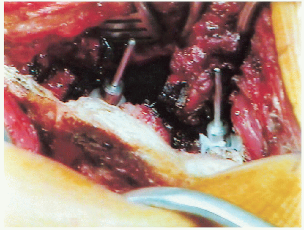
|
FIGURE 19-26. Insertion of pedicle screw.
|
 |
|
FIGURE 19-27. A: Rod and screw construct (see B, side view). B: Rod and screw construct.
|
 |
|
FIGURE 19-28. Placement of iliac crest bone graft into posterolateral gutter.
|
 |
|
FIGURE 19-29. Anteroposterior x-ray film after anterior lumbar interbody fusion (ALIF) (arrow at femoral ring).
|
 |
|
FIGURE 19-30. A: Anteroposterior x-ray film of final construct. B: Lateral x-ray film of final construct.
|
wound care and mobilization of the patient. Generally the patient is
fitted for a lumbosacral orthosis. Following discharge the patient is
encouraged to increase activity gradually while maintaining lifting,
bending, and squatting restrictions. Physical therapy is implemented on
an outpatient basis to provide a structured exercise program. Part-time
sedentary work is allowed at 4 to 6 weeks. After 3 months the orthosis
is discontinued and the patient is allowed to return to full time
employment with light to moderate activity. Full heavy labor and
vigorous activities may resume 6 months after surgery.
Degenerative spondylolisthesis with spinal stenosis: a prospective
study comparing decompression with decompression and intertransverse
process arthrodesis. J Bone Joint Surg Am 1991; 73A: 802.