
of end-stage arthritis of the hip offering both patients and physicians
a reliable treatment option that relieves pain and improves function.
When compared with other medical and surgical interventions for common
diseases, the cost of quality-adjusted life years associated with total
hip arthroplasty is nearly unparalleled and it is felt to be among the
most cost effective of all medical interventions available. It is
estimated that more than 150,000 total hip arthroplasties are now
performed annually in the United States. Given the aging of the
population that is expected to occur over the next several decades, the
number of patients requiring treatment of arthritis of the hip will
increase greatly making an appropriate understanding of the surgical
indications for and basic techniques of total hip arthroplasty
imperative for orthopaedic surgeons. Hybrid total hip arthroplasty
(insertion of a cementless acetabular component and a cemented femoral
component) has emerged as a reliable method for prosthetic fixation and
this chapter reviews indepth the surgical technique for this procedure.
cartilaginous surfaces of the femoral head and the pelvic acetabulum.
The femoral neck forms an angle with the femoral shaft that ranges
between 120 and 140 degrees with approximately 10 to 15 degrees of
anteversion. The femur itself has an anterior and somewhat lateral bow
that must be appreciated during femoral canal preparation. The
acetabular surface is oriented approximately 45 degrees caudally and 15
degrees anteriorly. Two strong columns of bone (anterior and posterior)
reinforce the acetabulum. Patients with a history of trauma or
developmental hip disease may have altered anatomy outside of these
ranges, and preoperative Judet views of the acetabulum or computed
tomography (CT) scanning may be appropriate to accurately define a
given patient’s anatomy.
include the anterior and posterior walls and the sciatic notch, which
can serve as guides to positioning the acetabular component. The base
of the fovea is used as a guide to determine the appropriate depth for
acetabular reaming. The transverse acetabular ligament marks the
inferior margin of the acetabulum.
painful, end-stage arthritis of the hip who have failed nonoperative
treatment (including the use of nonsteroidal antiinflammatory
medications, the use of an assist device in the opposite hand, and
activity modification) and for whom alternative reconstructive
procedures are not deemed appropriate. Patients must also be willing to
comply with the necessary precautions for avoiding dislocation and
early mechanical failure of the prosthesis. When performed in the
appropriate patient population, the cost to quality-adjusted life years
ratio for total hip arthroplasty is unparalleled when compared with
other medical interventions.
groin and/or proximal thigh along with corroborative physical
examination and radiographic findings to confirm the presence of
end-stage hip arthritis. The physical examination should include a
thorough assessment of the lower back and other areas extrinsic to the
hip to ensure that the hip pain experienced by the patient is not
referred from a distant source. In cases in
which the cause of the patient’s pain is unclear (e.g., a patient with
both hip and back pain as well as radiographic evidence of significant
hip and lumbar spine arthrosis), we have successfully used an
intraarticular lidocaine injection into the hip to confirm that the
pain is arising from the hip joint. A clinical assessment for presence of a leg-length discrepancy is an integral portion of the physical examination.
The presence of a significant hip flexion or adduction contracture is
also important to note preoperatively so that these can be addressed at
the time of surgery.
include arthrodesis, osteotomy, and arthroplasty. Arthrodesis of the
hip is performed infrequently at our institution. It is reserved for
young (<40 years old), usually male patients who have unilateral hip
arthritis, and no history of pain in the lower back, spine, or
contralateral hip. Patients who are unwilling or unable to comply with
the lifestyle changes that are compatible with a successful
arthroplasty (such as those who are manual laborers or have a history
of recent intravenous drug abuse) are also considered for hip
arthrodesis. Patients with inflammatory arthritis and nontraumatic
osteonecrosis of the hip are poor candidates for arthrodesis given the
high risk for involvement of the contralateral hip; in these patients,
arthroplasty is a better option.
focal biomechanical derangement of the hip joint with an adjacent area
of intact cartilage available for redirection into the weight-bearing
portion of the joint. Osteotomy can be performed on either the femoral
or the acetabular side of the joint. A congruous joint with good range
of motion is a prerequisite. These procedures are most often used in
younger patients with early degenerative arthritis secondary to the
residua of developmental dysplasia of the hip or in those patients with
early osteonecrosis (no evidence of acetabular degeneration) and a
small area of femoral head involvement. Osteotomy is contraindicated in
patients with inflammatory arthritis, given the typical concentric
nature of the cartilaginous destruction in these patients and the
expectation of further joint destruction.
arthroplasty have shown survivorship of a cemented femoral component to
be more than 90% at 20 years, with higher rates of both clinical and
radiographic failure of the cemented acetabular component. This has
lead to increased interest in the use of acetabular components inserted
without cement to improve prosthetic longevity. Clinical studies
demonstrate decreased rates of clinical and radiographic failure at
intermediate term follow-up and support the use of these devices. The
use of a cemented femoral component and an acetabular component
inserted without cement (hybrid total hip arthroplasty) has met with
excellent clinical success and is appropriate for most patients
undergoing total hip arthroplasty. Although the use of femoral
components inserted without cement has increased and midterm results
appear promising, the excellent long-term results observed for femoral
components inserted with modern cement techniques justify their
continued widespread use.
patients with active joint sepsis and patients who are unwilling or
unable to comply with the lifestyle changes compatible with a
successful total hip arthroplasty. Relative contraindications are
patients with severe medical comorbidities that make them poor surgical
candidates and patients with paralysis
of the abductor musculature that would make postoperative instability a great concern.
 |
|
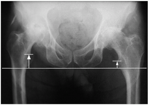
FIGURE 20-1. Leg-length determination on anteroposterior radiograph.
|
 |
|
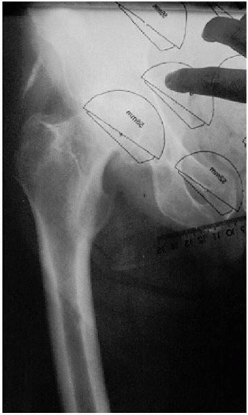
FIGURE 20-2. Acetabular component templating.
|
an anteroposterior (AP) view of the pelvis, centered low to include the
proximal half of the femur, as well as a lateral radiograph of the hip.
A line drawn tangential to the bottom of the ischial tuberosities is
used to determine the amount of preoperative leg-length discrepancy as
the difference between this line and the top of the lesser trochanter
bilaterally (Fig. 20-1). Clear overlay
templates provided by the manufacturer are then used to approximate the
level of the femoral neck cut and the size of the acetabular and
femoral components to be used. The acetabular component should lie next
to the acetabular teardrop medially (i.e., the outer table of the
medial wall of the acetabulum), and the new center of rotation of the
hip is marked on the radiograph (Fig. 20-2).
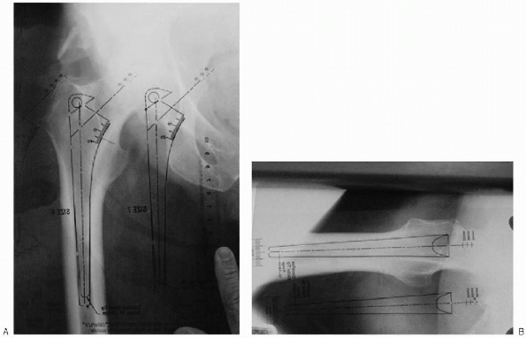
The previously selected femoral component template is then placed over
the radiograph and rotated around the new center of rotation of the hip
until it lies within the femoral canal in both AP and lateral
projections (Fig. 20-3A and B). A prosthesis of
appropriate size and neck length should be selected that will to
re-create the patient’s femoral offset (distance from the center of the
femoral head to the central axis of the femoral shaft). The level of
the femoral neck osteotomy is then estimated and marked with an
appropriate compensation made to equalize leg lengths as determined on
the AP radiograph of the pelvis.
 |
|
FIGURE 20-3. Femoral component templating. A: Anteroposterior. B: Lateral.
|
a medical internist is mandatory to identify patients at high risk for
perioperative morbidity and mortality who may benefit from preoperative
medical optimization. Clinical issues that should be screened for and
resolved before total hip arthroplasty include dental disorders,
urinary tract disorders (outlet obstruction in men or recurrent
infection in women), and any skin disorders or lesions; all of these
may contribute to recurrent postoperative bacteremia. Patients with
appropriate preoperative hemoglobin levels are encouraged to donate one
unit of autologous blood preoperatively.
-
Large bone hook
-
Mallet
-
Cobb elevator
-
Standard and long knife handles
-
Standard and long cautery blades
 |
|
FIGURE 20-4. Retraction devices: anterior acetabular retractor (left); Charnley incisional retractor with regular and deep blades (middle top); broad femoral neck (jaws) retractor (middle bottom); small, medium, and large double-prong wing retractors with insertion handle (right).
|
-
Charnley incisional retractor with regular and deep blades
-
Morris retractor
-
Hohman retractors regular and bent
-
Double-prong wing retractors with insertion handle; small, medium, and large
-
Anterior acetabular retractor
-
Broad femoral neck (jaws) retractor
-
Blunt-tipped Charnley tapered reamer (canal finder)
-
Harris curette
-
Femoral reamers
-
Femoral broach trial
-
Femoral broach handle
-
Acetabular reamers and trials
-
Bone screw instruments
 |
|
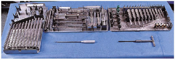
FIGURE 20-5. Bone preparation: Femoral reamers (left tray); femoral broach handle (middle tray, top); Harris curette (middle bottom); Femoral broach trial (right tray, top); blunt-tipped Charnley tapered reamer (canal finder) (bottom right).
|
 |
|
FIGURE 20-6. Acetabular reamers and trials (top trays); bone screw instruments (bottom tray).
|
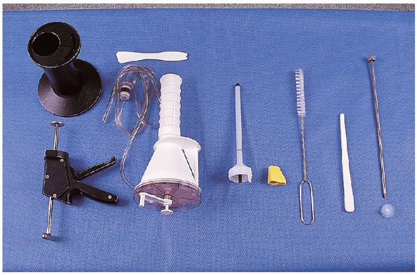
-
Cement gun kit with vacuum attachment
-
Break-away nozzle
-
Cement pressurizer
-
Femoral brush
-
Tampon for drying femoral canal
-
Bucks cement restrictor
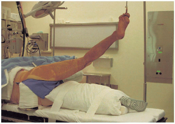
total hip arthroplasty to avoid iatrogenic injury and to ensure
appropriate siting of anatomic landmarks for component positioning. We
use a hip positioner that firmly secures the patient to the operating
table in the lateral decubitus position. In
markedly obese patients, the positioner is angled with the anterior
portion more caudad, to allow for firm contact with the anterior
superior iliac spine without undue soft tissue compression. The
down leg has a foam pad placed beneath the knee at the fibular head (to
protect the peroneal nerve) and beneath the lateral malleolus to
prevent pressure-induced injury (Fig. 20-8A and B).
The abdominal area must be well padded, particularly in obese patients.
An axillary roll, made from carefully rolled sheets, is used on the
upper
chest to protect the brachial plexus on the down
side from injury. A pillow is placed between the legs to pad the down
leg, and is taped into place. The operative table must be level
with the floor and the pelvis should be perpendicular to the floor to
allow for accurate positioning of the acetabular component (Fig. 20-9).
 |
|
FIGURE 20-7. Cement equipment (left to right): cement gun with vacuum attachment (left); breakaway nozzle, cement pressurizer (yellow), femoral brush, tampon for drying femoral canal, Bucks cement restrictor.
|
 |
|
FIGURE 20-8. Patient preparation. A: Knee pad. B: Lateral malleolar pad.
|
range of motion to ensure that 90 degrees of flexion is possible with
the patient firmly secured in the positioner. A first-generation
cephalosporin (or clindamycin in patients with known allergies to
penicillin or cephalosporins) is administered preoperatively. The
entire extremity is then prepped from above the iliac crest to include
the foot, sequentially using Betadine scrub and paint. The foot is
covered with a glove and the extremity draped in a full-length
stockinette. The area of the surgical incisions is covered with an
iodinated nonpermeable adhesive. The surgical team wears body exhaust
hoods during the procedure.
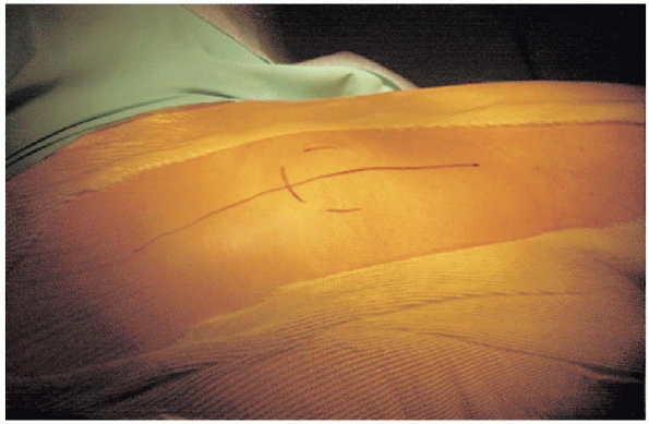
incision is the greater trochanter, which is palpable beneath the skin.
The anterior superior iliac spine is another useful landmark for
determining the most proximal extent of the incision; this is
particularly useful in patients with a high developmental dislocation
of the hip. The area of the greater trochanter is identified, as is the
femoral shaft. Abduction of the leg can assist in identifying the tip
of the greater trochanter. A 15-cm skin incision with a gentle
posterior curve is planned. The incision is centered over the greater
trochanter and in line with the femur with the hip held in
approximately 30 degrees of flexion (Fig. 20-10).
 |
|
FIGURE 20-9. Patient positioning for surgical prep.
|
divided in the line of the incision until the deep fascia layer is
identified (Fig. 20-11). Care
is taken to confirm appropriate positioning inline with the femoral
shaft during the dissection to prevent drifting either anterior or
posterior to the femur, which will make subsequent exposure more
difficult. Hemostasis is obtained with electrocautery and the deep fascia is divided, taking care not to damage the underlying muscle. Abduction of the hip during the incision of the fascia
lessens the risk of injury to the underlying muscle.
The deep fascia is then split in line with its fibers to expose the
underlying bursae and short external rotators of the hip, and a
Charnley type self-retaining retractor is placed into the wound. The knee is maintained in flexion, and the hip is held extended to avoid placing undue tension on the sciatic nerve.
 |
|
FIGURE 20-10. Outline of incision with greater trochanter marked.
|
 |
|
FIGURE 20-11.
Subcutaneous tissue has been divided and the deep fascial layer is identified. The femur is palpated beneath this layer to ensure that the incision in the deep fascia layer is centered appropriately. |
then incised and the short external rotators are identified. Great care
is taken to identify and fully cauterize all vessels that lie on the
surface of the short external rotators of the hip. The extremity is now
placed into internal rotation to place tension on the short external
rotators and a Homan retractor is placed over the piriformis tendon (Fig. 20-12). The short external rotators are then tenotomized, using the electrocautery to expose the underlying capsule (Fig. 20-13).
Although usually unnecessary for routine total hip arthroplasty, the
quadratus femoris muscle can be released from the femur if needed. If
the quadratus femoris muscle is to be released, one must take care to
identify and cauterize the large branch of the medial femoral
circumflex artery that lies within the muscle belly. If
additional exposure is needed, up to half of the gluteus maximus
insertion from the femoral shaft can also be released. An elliptically
shaped capsulectomy is then performed, and the hip is carefully
dislocated with the assistance of a large bone hook, using a
combination of flexion, internal rotation, and adduction. The
hip should be dislocated with the use of traction by a large bone hook
rather than forceful levering of the leg and femur by the second
assistant. This avoids femoral shaft fractures in osteopenic patients.
 |
|
FIGURE 20-12. Homan retractor is placed over the piriformis tendon.
|
 |
|
FIGURE 20-13. The short external rotators of the hip are tenotomized with an electrocautery to expose the underlying capsule.
|
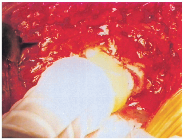
the center of the prosthetic head (with a plus 5-mm neck length) is aligned with the center of the native femoral head (Fig. 20-14).
A plus 5-mm neck is used so that a shorter or longer neck size is
available if changes are necessary at the time of trial reduction. The
level and inclination of the femoral neck osteotomy are then marked
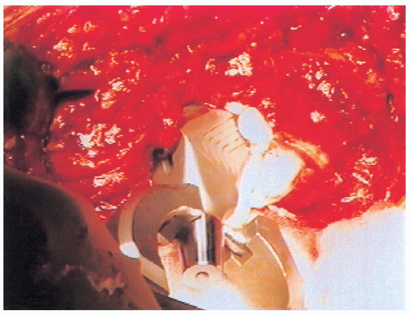
using the electrocautery. The osteotomy is performed with an oscillating saw (Fig. 20-15),
while the assistant on the other side of the table holds the extremity
with the thigh parallel to the floor and the knee flexed, so that the
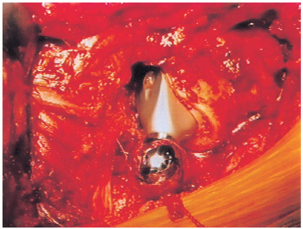
lower leg is perpendicular to the floor. An osteotome can be used to
complete the superior portion of the femoral neck osteotomy if
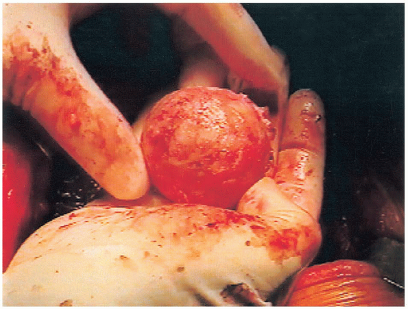
necessary (Figs. 20-16 and 20-17). 
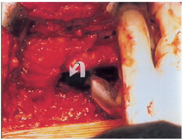
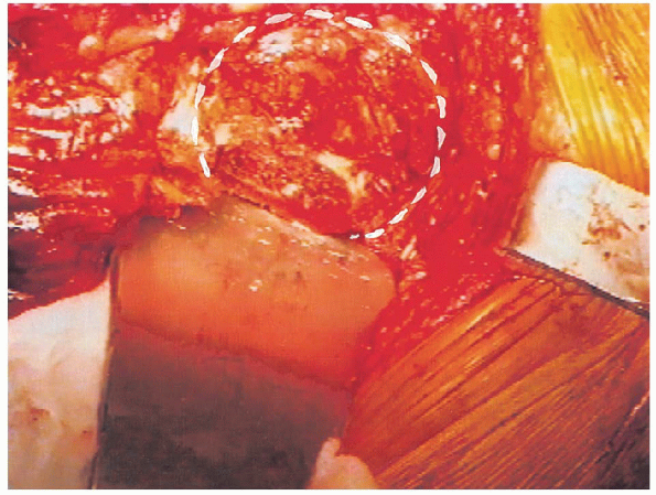
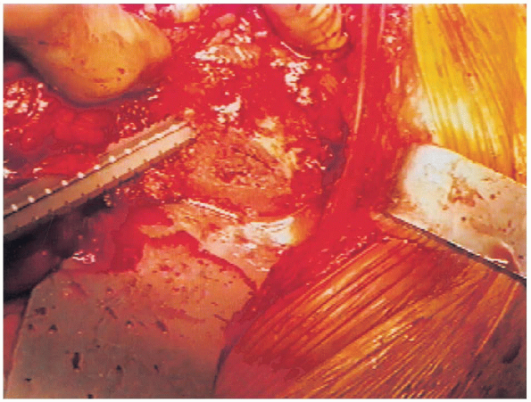
The proximal femur is then lifted superiorly with a large bone hook by
the assistant on the other side of the table, and with the
electrocautery a rent is made in the anterior hip capsule for placement
of the anterior acetabular retractor (Fig. 20-18). An anterior retractor is then used to keep the proximal femur out of the way during acetabular preparation. Great
care must be taken to keep the tip of the anterior acetabular retractor
from straying too far medially to avoid damage to the femoral
neurovascular bundle.
 |
|
FIGURE 20-14. Planning of femoral neck osteotomy with trial prosthesis.
|
 |
|
FIGURE 20-15. Femoral neck osteotomy with oscillating saw.
|
 |
|
FIGURE 20-16. Completion of femoral neck osteotomy with osteotome.
|
 |
|
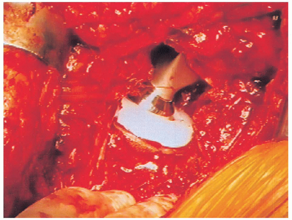
FIGURE 20-17. Femoral head after removal, showing osteoarthritic changes.
|
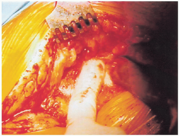
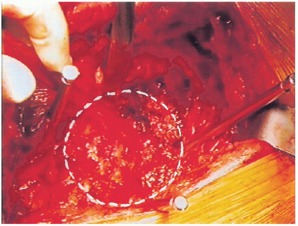
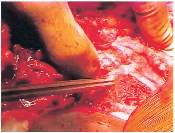
retractors are then impacted into the iliac wing superiorly and ischium
posteriorly to provide circumferential acetabular exposure (Figs. 20-19 and 20-20).
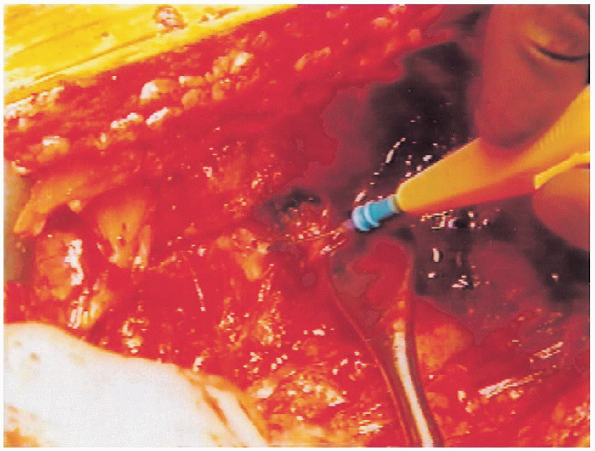
The remaining labrum and associated soft tissues are then carefully resected using the electrocautery. Greatcare is exercised when resecting the soft tissue in the inferior aspect
of the acetabulum and pulvinar. Specifically, no tension is placed on
the soft tissues inferiorly while they are being resected; this is to
avoid injury to a branch of the obturator vessels that can then retract
and cause profuse bleeding. After removal of the pulvinar, the
medial wall of the acetabulum is visualized and acetabular reaming is
then performed directly medially until the acetabular floor is
identified. Sequential reaming is then performed with the reamer held
in approximately 40 degrees of cup abduction and 10 degrees of
anteversion until subchondral bone is identified and a perfect
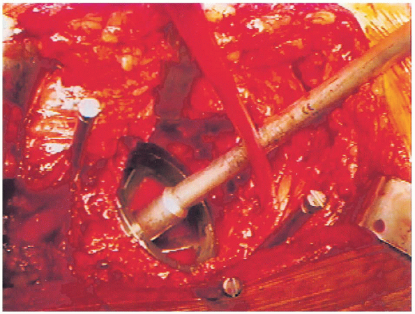
hemisphere has been created (Fig. 20-21).
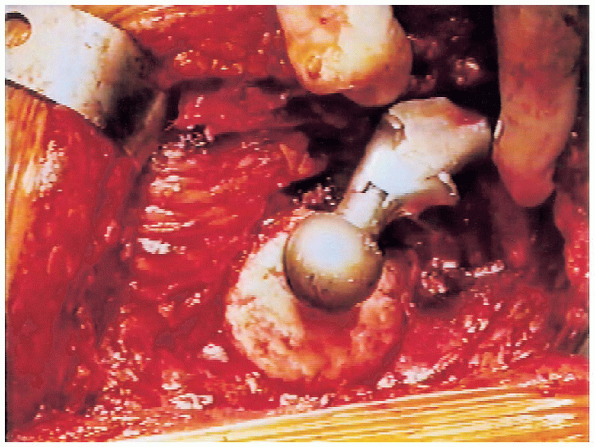
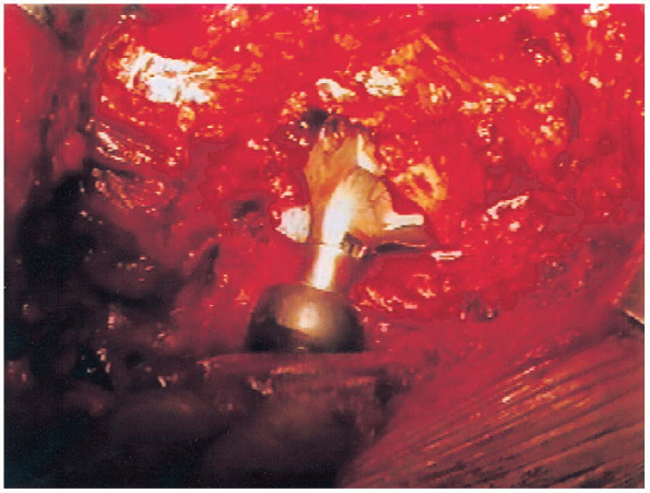
An acetabular trial that is the same size as the final reamer used is theninserted and tested for size and fit (Fig. 20-22).
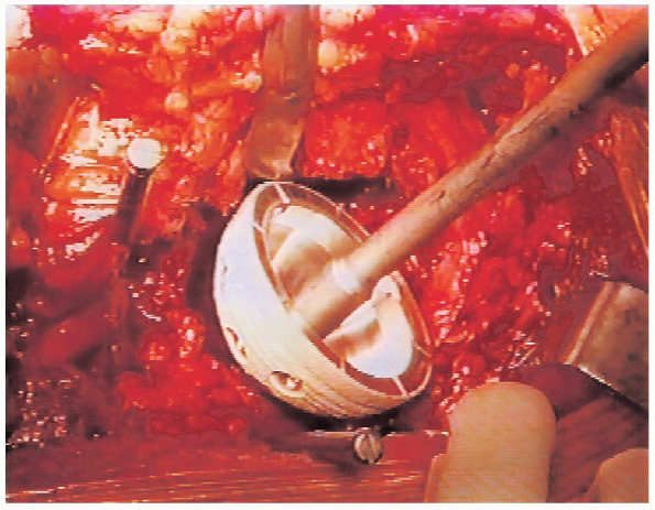
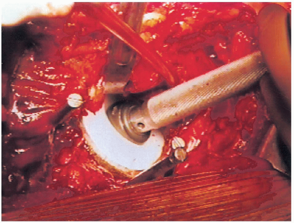
A reamer 2 mm smaller than the last used is then placed into reverse
and used to impact morselized bone from the resected femoral head into
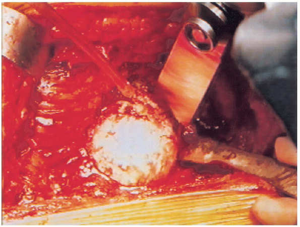
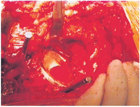
the acetabulum (Fig. 20-23). The acetabular component selected is next impacted into place in 40 degree of cup abduction and 10 degrees of anteversion (Figs. 20-24 and 20-25).
The component we use is approximately 0.75 mm larger in diameter than
labeled because of macro-texturing, resulting in increased interference
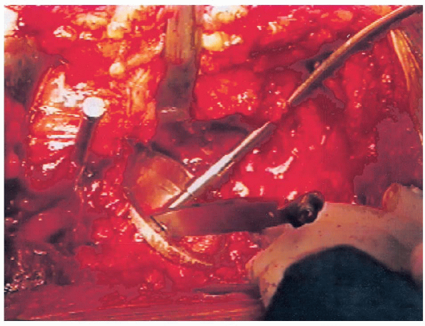
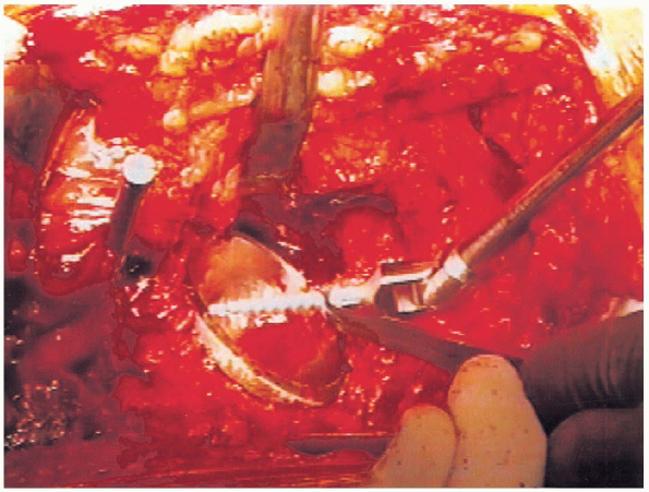
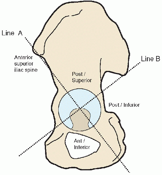
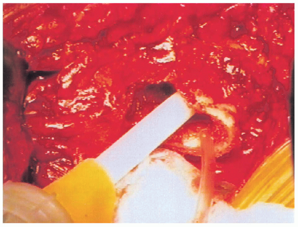
fit. Two screws placed into the posterior-superior quadrant (as
described by Wasielewski) are then used to augment initial stability
(rarely longer than 25 mm, because longer screws may exit the pelvis
and endanger surrounding neurovascular structures) (Figs. 20-26 and 20-27).
This system divides the acetabulum into halves from the anterior
superior iliac spine caudally and then bisects this line to form four
quadrants (Fig. 20-28). In their anatomic study
of cadavers, Wasielewski et al. found that the posterior-superior
quadrant offered the greatest margin of safety and the highest quality
bone for adjunctive screw fixation. We routinely use
a 10-degree elevated rim liner that is placed in the posterior-superior portion of the component (Fig. 20-29).
Polyethylene thickness is maintained at a minimum of 8 mm. The
acetabulum is protected with a lap sponge, and femoral preparation is
begun after removal of the acetabular retractors.
 |
|
FIGURE 20-18. Placement of anterior acetabular retractor.
|
 |
|
FIGURE 20-19. Placement of posterior wing retractor for acetabular exposure.
|
 |
|
FIGURE 20-20. Circumferential acetabular exposure obtained.
|
 |
|
FIGURE 20-21. Reamer in acetabulum.
|
 |
|
FIGURE 20-22. Trial acetabular component in place.
|
 |
|
FIGURE 20-23. Placement of morselized bone graft into the acetabulum.
|
 |
|
FIGURE 20-24. Component before final seating.
|
 |
|
FIGURE 20-25. Final appearance of inserted acetabular component.
|
 |
|
FIGURE 20-26. Drilling for acetabular screws.
|
 |
|
FIGURE 20-27. Placement of acetabular screw.
|
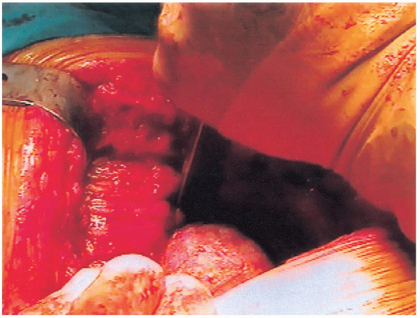
Any remaining soft tissue is removed from the base of the femoral neck.
A blunt T-handle reamer is used to identify the central portion of the
femoral canal followed by sequential reaming until cortical bone is
reached (Figs. 20-31 and 20-32). Great care is taken to avoid eccentric reaming of the canal. A Harris curette can
then be used to confirm that sufficient reaming has been performed so
that cortical bone is present circumferentially in the distal canal.
For cement application, a reamer two sizes larger than the component is
used to create a cement mantle of appropriate thickness. The
lower extremity is then positioned with the leg held perpendicular to
the ground for appropriate estimation of femoral version during
broaching. Broaching is then carefully performed, starting with
the smallest broach, until adequate fit and fill are achieved with the
broach held in approximately 15 degrees of anteversion (Fig. 20-33).
Care is taken to avoid varus positioning of the broach by maintaining
the broach handle in a lateral position, hugging the base of the
greater trochanter during insertion. Broaching is
carried out by allowing the mallet to fall onto the top of the
insertion handle but not with undue force. If the broach fails to
advance, the next smallest sized broach is reinserted and advanced, and
then the larger size is attempted again to avoid causing a fracture.
The appropriate-sized femoral head with a plus 5-mm neck (as was used
initially to intraoperatively template the level of the femoral neck
cut) is then placed onto a full-sized collared trial component (Fig. 20-34)
in preparation for the trial reduction. The hip is reduced with the
assistance of a bone hook and brought through a range of motion after
the Charnley retractor is loosened to assess stability. If
the hip is trialed while the Charnley retractor is tight, the surgeon
may overestimate stability secondary to the soft tissue tension
provided by the retractor, leading to problems with postoperative
dislocation. If trial reduction reveals inadequate or excessive
soft tissue tension, a longer or shorter neck length is trialed before
final component selection. In general, the
center of the prosthetic femoral head should lie at the level of the
greater trochanter if leg-length equalization has been carried out.
A lap pad is placed beneath the trial head before it is removed from
the wound to ensure that it is easily retrievable if it becomes
dislodged from the femoral stem. If inadequate stability is observed,
the surgeon must search for sources of bony or prosthetic impingement
or adjust the version of the femoral or acetabular components as needed.
 |
|
FIGURE 20-28. Quadrant system for safe placement of acetabular screws.
|
 |
|
FIGURE 20-29. Insertion of polyethylene liner.
|
 |
|
FIGURE 20-30. Exposure of proximal femur with retractor.
|
 |
|
FIGURE 20-31. Insertion of blunt T-handled reamer.
|
 |
|
FIGURE 20-32. Insertion of femoral reamer.
|
 |
|
FIGURE 20-33. Femoral broach in place.
|
 |
|
FIGURE 20-34. Full-size collared trial in place.
|
 |
|
FIGURE 20-35. Estimation for depth of cement restrictor.
|
 |
|
FIGURE 20-36. Insertion of cement into femoral canal.
|
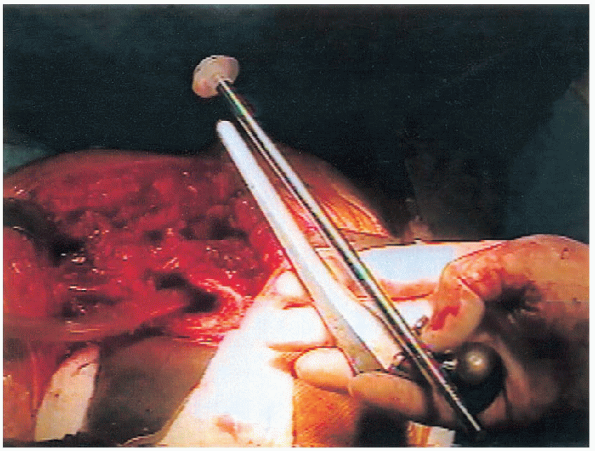
the appropriate-sized components have been selected the femoral canal
is prepared. A cement restrictor is inserted to a depth of at least 1
cm deeper than the tip of the prosthesis (Fig. 20-35).
For optimal cement technique to be achieved, the femoral canal is
irrigated and dried to remove all blood, marrow contents, and debris.
Two packages of cement are then mixed under suction and inserted into
the femoral canal in a retrograde manner, using a cement gun once the
cement has reached a doughy consistency (Fig. 20-36). After insertion into the canal, the cement is pressurized to maximize the quality of the cement mantle (Fig. 20-37).
We do not use a proximal or distal centralizer on the femoral stem,
because we are concerned that these devices can create imperfections
within the cement mantle. In addition, it is our experience
centralizers do not improve component positioning or cement technique.
The stem is inserted in the same version as the trial components,
taking care to hold the lower leg perpendicular to the floor throughout
cementation (Fig. 20-38).
Any extruding cement istrimmed.
The hip is then trialed a second time after the cement has fully
hardened to confirm neck length for optimal stability. The Morse taper
is now cleaned and dried, and the modular femoral head is gently
impacted onto the Morse taper (Fig. 20-39).
 |
|
FIGURE 20-37. Pressurization of cement.
|
 |
|
FIGURE 20-38. Insertion of femoral component.
|
 |
|
FIGURE 20-39. Femoral component with modular head in place.
|
 |
|
FIGURE 20-40. Final reduction of components.
|
the wound is copiously irrigated with sterile saline, and a large
Hemovac is placed into the wound exiting distally and in a nondependent
position (anterior to the incision). The deep fascia is closed with an
absorbable, nonbraided heavy suture, followed by closure of the
subcutaneous tissues with inverted absorbable sutures and skin staples.
A postoperative radiograph of the hip is obtained to confirm
appropriate component position.
24 hours postoperatively. A first-generation cephalosporin or
clindamycin in patients with a penicillin allergy is used. The surgical
drains are removed on the morning after surgery. We use 325 mg of
aspirin daily, in conjunction with elastic compression stockings and
mechanical foot pumps for thromboembolic prophylaxis. A pillow is kept
between the patient’s legs at all times, and patients may lie on the
operative side while sleeping if desired.
with a physical therapist and are weight bearing as tolerated on the
operative extremity initially with the use of a walker. Patients are
first out of bed to a hip chair and are then instructed in progressive
ambulation as tolerated. Physical and occupational therapy includes
instruction in total hip precautions with avoidance of hip flexion of
greater than 90 degrees and any degree of internal rotation or
adduction. Patients are discharged with Lofstrand crutches and are
advanced to the use of a cane in the contralateral hand at the
discretion of a home physical therapist (usually at 3 weeks). The
occupational therapy department arranges for the use of an elevated
toilet seat and additional devices, such as reachers, sock-aides, long
shoe horns, elastic shoe laces (for conversion of a laced shoe to a
slip on), and shower seats, as indicated. Patients use an assist-device
for the first month, which is discontinued later at the discretion of
the surgeon.
performed at 1, 6, and 12 months and then annually. Follow-up is
important to make early determination of failure mechanisms such as
osteolysis and component wear and loosening that can be addressed
before major bone compromise has occurred.
Radiographic comparison of grit-blasted hydroxyapatite and
arc-deposited hydroxyapatite acetabular components. A four-year
follow-up study. Bull Hosp Joint Dis 2000;59(3):144-148.
Charnley total hip arthroplasty with use of improved techniques of
cementing. The results after a minimum of fifteen years of follow-up. J Bone Joint Surg Am 1997;79:53-64.
Total hip arthroplasty performed with insertion of the femoral
component with cement and the acetabular component without cement. Ten
to thirteen-year results. J Bone Joint Surg Am 1997;79:1827-1833.