
in the geriatric population, with an impact that extends far beyond the
obvious orthopaedic injury into the domains of medicine,
rehabilitation, psychiatry, social work, and medical economics. Despite
improvements in patient care, including advances in operative technique
and implant technology, fractures of the proximal femur continue to
consume a major portion of national health care resources. The
increasing number of hip fractures that occur each year has made it
difficult to keep pace with this growing health care problem. With the
aging of the U.S. population, the annual number of hip fractures is
projected to double by the year 2050. This chapter describes
hemiarthroplasty of a displaced femoral neck fracture.
the region between the base of the femoral head and the
intertrochanteric line anteriorly and the intertrochanteric crest
posteriorly (see Fig. 23-1). The femoral neck
forms an angle with the femoral shaft ranging from 125 to 140 degrees
in the anteroposterior plane and 10 to 15 degrees (anteversion) in the
lateral plane. The cancellous bone of the femoral neck is characterized
by trabeculae organized into medial and lateral systems. The medial
trabecular system forms in response to the joint reaction force on the
femoral head; the epiphyseal plates are perpendicular to the medial
trabecular system. The lateral trabecular system resists the
compressive force on the femoral head resulting from contraction of the
abductor muscles (see Fig. 21-1).
 |
|
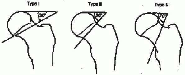
FIGURE 22-1. The Pauwels classification of femoral neck fractures. From Rockwood CA, Jr., Green DP, Bucholz RW, Heckman JO, eds. Rockwood and Green’s fractures in adults, 4th ed; vol. 2. Philadelphia: Lippincott-Raven, 1996: 1670, with permission.
|
fractures have been proposed. One such scheme is anatomically based and
divides the femoral neck into three regions: subcapital, transcervical,
and basocervical (see Fig. 21-2). Most femoral
neck fractures are subcapital; transcervical femoral neck fractures are
usually the result of repetitive stresses. Because the subcapital and
transcervical regions are entirely intracapsular, fractures in these
regions exhibit different characteristics from those in the
basocervical region, which is extracapsular. Fractures that are
entirely intracapsular are at increased risk for osteonecrosis and
nonunion, sequelae that are uncommon after extracapsular fracture.
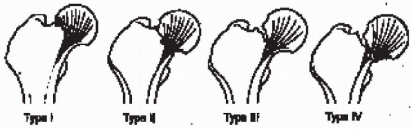
system, introduced by Garden in 1961, has four types based on the
degree of fracture displacement on the anteroposterior radiograph (Fig. 22-2):
bony trabeculae of the inferior portion of the femoral neck remains
intact (including “valgus-impacted” fractures)
 |
|
FIGURE 22-2. The Garden classification of femoral neck fractures. From Hansen S, Swiontkowski M, Orthopedic trauma protocols. New York: Raven Press, 1993:238.
|
the fracture fragments, allowing the femoral head to rotate back to an
anatomical position (radiographically, the bony trabeculae of the
femoral head line up with the bony trabeculae of the acetabulum)
best—approach is to classify femoral neck fractures as nondisplaced
(Garden types I and II) or displaced (Garden types III and IV). Further
differentiation can be difficult to establish radiographically and has
been shown to be subject to wide variability. The
nondisplaced/displaced scheme, which has the virtue of grouping
together fractures with similar treatment alternatives and similar
prognoses, is my preference for classifying femoral neck fractures.
healthy, low-demand individuals who have sustained a displaced femoral
neck fracture. Factors favoring prosthetic replacement over internal
fixation include pathologic bone, comminution of the posterior femoral
neck, severe chronic illness (especially rheumatoid arthritis and
chronic renal failure), and a limited life expectancy. Inactive elderly
patients are candidates for modular or Austin-Moore-type unipolar
hemiarthroplasty. Those with displaced femoral neck fractures who can
ambulate functionally outside the home (i.e., community ambulators) and
whose likelihood of success with internal fixation is low should
receive a modular unipolar or bipolar hemiarthroplasty—with the
awareness that revision may be required in the future because of
loosening of the femoral component or acetabular degenerative changes,
including protrusion. The risk of these problems is greater in younger,
more active individuals.
 |
|
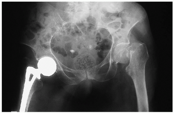
FIGURE 22-3. Anteroposterior radiograph of the pelvis demonstrates a displaced, left femoral neck fracture.
|
-
Anteroposterior view of the pelvis (Fig. 22-3)
-
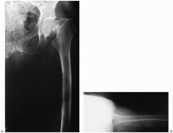
Anteroposterior and cross-table lateral view of the involved proximal femur (Fig. 22-4)
to perform preoperative templating to determine the approximate femoral
stem and unipolar or bipolar head size. In most patients, the normal
hip is used as a template to duplicate normal leg length and hip
offset. Proper hip offset helps maintain proper soft tissue tension,
which is critical to the stability and biomechanics of the hip.
 |
|
FIGURE 22-4. Anteroposterior (A) and lateral cross-table (B) views of the left hip demonstrate a displaced femoral neck fracture.
|
pelvis that includes as much of the proximal femur as possible. The
pelvis should not be rotated, and it is helpful if the noninjured leg
is rotated internally 15 degrees to get a true profile view of the
proximal femur (this eliminates the normal anteversion). It is not
necessary to obtain this view of the injured extremity. On the
anteroposterior view, the center of the head is marked on the
noninjured hip. The center can be determined by using a ruler to
calculate the diameter of the head and then identifying the midpoint. A
line is then drawn down the center of the femoral shaft. The distance
from this line to the center of the femoral head is the hip offset.
magnification, a stem of appropriate size is chosen. It is important to
check that the stem also matches both anteroposterior and lateral views
of the injured hip before templating on the normal hip. For cemented
insertion, adequate space must be maintained around the stem to
accommodate the cement mantle (usually 2 mm). This calls for a smaller
stem than for noncemented, press-fit insertion. For noncemented,
press-fit insertion, the best fit is chosen to achieve intimate bony
contact, which may be metaphyseal or diaphyseal depending on type of
implant chosen.
It is then slid down the canal until one of the neck length markings
matches the offset of the normal hip. The distance from this marking
down to the lesser trochanter is measured using the magnified ruler
markings on the template. This distance is recorded and later measured
intraoperatively to mark the level of the desired neck cut. The
distance from the lesser trochanter to the center of the femoral head
is also measured to recreate this distance intraoperatively. The neck
length marking on the template that most closely matches the offset of
the normal hip is the neck length that will be used first when
performing an intraoperative trial and—assuming intraoperative
stability—for the prosthesis itself.
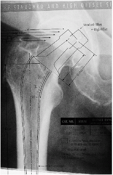
available on the templates. These patients usually need a prosthesis
with a high-offset geometry. If a high-offset stem is not used, the
soft tissue tension of the hip abductors will be subnormal;
these muscles may function suboptimally, and hip stability may be compromised.
 |
|
FIGURE 22-5. Use of a template to determine the optimal femoral stem size.
|
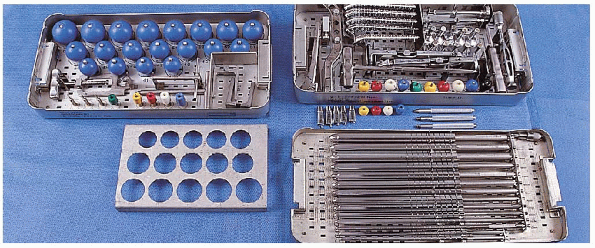
the hip after femoral neck fracture include femoral head and neck
trials, femoral head sizers, broaches, and a reamer set (Fig. 22-6).
 |
|
FIGURE 22-6. Equipment for cemented unipolar hemiarthroplasty for a femoral neck fracture: femoral head and neck trials (left tray, top); femoral head sizers (left tray, bottom); broaches (right tray, top); and reamer set (right tray, bottom).
|
 |
|
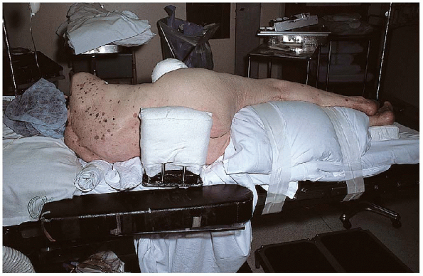
FIGURE 22-7. Use of a lateral position to hold the patient in a lateral decubitus position.
|
femoral neck fracture, I most commonly use a posterior approach, with
the patient in the lateral decubitus position. A lateral positioner is
used to maintain this position, and a soft axillary roll is placed
under the upper thorax to protect the brachial plexus (Fig. 22-7).
The ankle and the knee of the noninjured leg are padded to prevent
iatrogenic nerve injury, and a pillow is placed between the legs to
help abduct the operative extremity and facilitate the exposure. Before
preparing the operative site, the hip is flexed to 90 degrees to ensure
that the lateral positioner is not blocking the range of hip motion.
The entire injured extremity is then prepared and draped up to and
including the iliac crest.
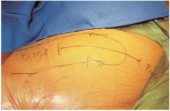
femur, centered over the greater trochanter with the hip flexed
approximately 30 degrees (Fig. 22-8). The
incision begins approximately 5 to 6 cm proximal to the greater
trochanter and continues the same distance distal to the greater
trochanter. The subcutaneous tissues are divided in line with the
incision and the fascia lata is identified. A periosteal elevator is
used to clear the fascia lata, which is then incised in line with the
femur. At the proximal aspect of the incision, the muscle fibers of the
gluteus maximus are visible as the fascia lata thins out superficial to
the maximus. The gluteus maximus fibers are bluntly split in an
anterior-to-posterior direction, and a Charnley retractor is inserted
deep to the fascia lata for exposure (Fig. 22-9). Care is taken to palpate the sciatic nerve and ensure that it is not trapped in the blades of the retractor.
 |
|
FIGURE 22-8. The skin incision for a posterior approach to the hip.
|
is maintained in extension during the posterior dissection; this
relieves the sciatic nerve of any unnecessary strain and assists the
exposure as the short external rotators are released. The sciatic nerve
is again palpated—it is not necessary to expose it—before beginning the
posterior exposure to ensure that it is not in danger of injury. A
blunt retractor is passed above the superior border of the piriformis,
deep to the gluteus minimus but superficial to the superior capsule, to
assist the exposure. The hip is internally rotated to place the short
external rotators under tension. Electrocautery is used to release the
short rotators and the underlying capsule directly off bone along the
posterior border of the proximal femur. The quadratus femoris is
partially released, as necessary. Perforating vessels are identified
and cauterized; there is usually a large branch of the medial femoral
circumflex within the body of the quadratus femoris. The short external
rotators can be reflected separately or in conjunction with the
posterior hip capsule. I prefer releasing the external rotators and
capsule together. It is helpful to make a T-type incision in the
capsule below the piriformis so that two sleeves of tissue overlay the
posterior hip joint; a suture is passed through each of these sleeves.
These sutures are helpful for retraction during reduction of the
prosthetic hip and for later capsular reattachment. The capsulotomy is
extended superiorly and inferiorly to enhance visualization of the
acetabulum.
 |
|
FIGURE 22-9. Placement of the Charnley retractor.
|
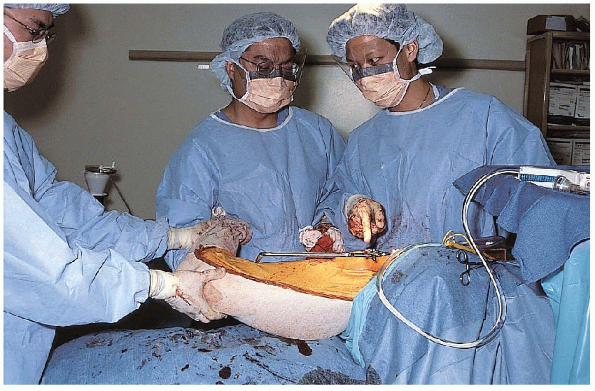
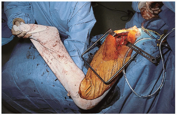
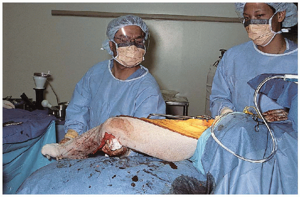
femur is flexed and internally rotated to expose the femoral neck. A
femoral neck osteotomy is performed using an oscillating saw, with the
extremity positioned so the foot is superior, pointing toward the
ceiling, and the leg perpendicular to the floor (Fig. 22-10).

The location of the cut with respect to the lesser trochanter is
determined by preoperative templating, and the angle of the cut is
matched to a trial or broach. Shortening of the
limb by excessive femoral neck resection and placement of a short
femoral neck component may increase the risk for prosthetic dislocation
because of soft tissue laxity—specifically the gluteus medius.
Lengthening of the affected limb is poorly tolerated by patients and
may result in increased pressure on the acetabular cartilage,
increasing the risk of acetabular erosion. As a general rule, the
femoral neck should be osteotomized approximately 1 cm proximal to the
lesser trochanter.
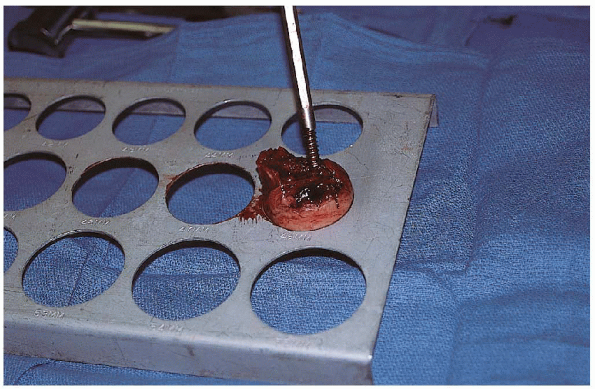
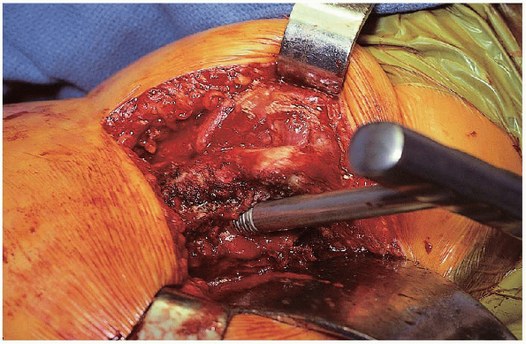
Osteotomy of the femoral neck before removal of the femoral head
enhances the exposure. The femoral head is extracted using a cork screw
and a skid ; it may be necessary to incise the ligamentum teres.
If exposure is difficult, a bone hook is passed under the femoral neck
and used to retract the femur. If exposure remains a problem and the
gluteus maximus is tight, the proximal portion (1 to 1.5 cm) of the
gluteus maximus insertion can be released off the linea aspera of the
femur using electrocautery. Care must be taken not to release too far
distally to minimize bleeding from perforating vessels.
 |
|
FIGURE 22-10. Positioning of the extremity with the foot superior, pointing toward the ceiling, and the leg perpendicular to the floor.
|
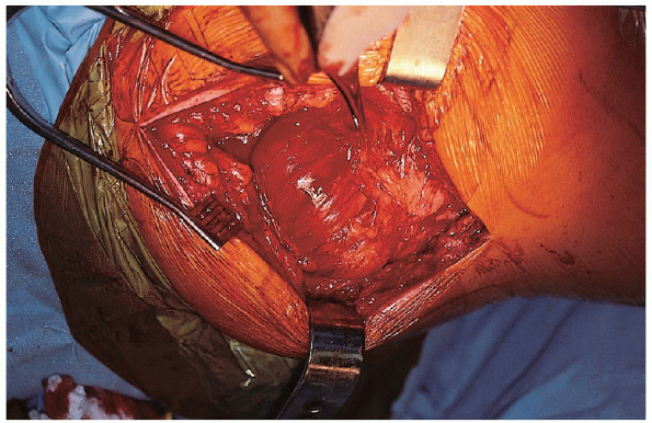
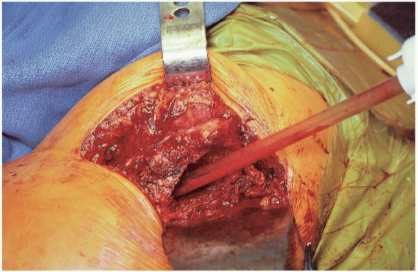
The acetabulum is visually inspected to evaluate the condition of the
cartilage. If the pulvinar is excessively large, it is trimmed using a
cautery. Trial heads of appropriate size are tested in the acetabulum
for a good suction fit, and the largest head that seats fully in the
acetabulum is selected.
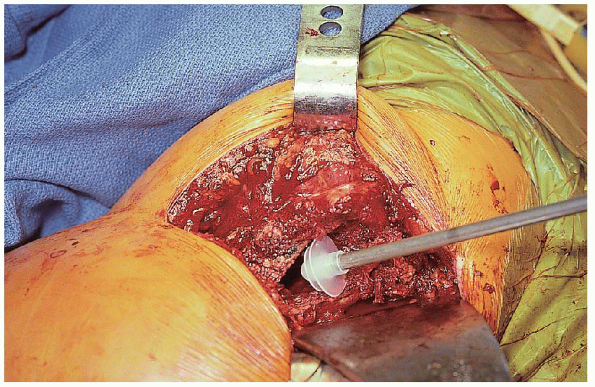
Placementof a prosthetic femoral head that is smaller in diameter than that
removed at surgery will result in asymmetric loads within the
acetabulum and an increased risk of acetabular wear and subsequent
protrusio; use of a larger-diameter prosthetic femoral head than that
removed at surgery may not fully seat within the acetabulum, increasing
the risk of prosthetic dislocation.
 |
|
FIGURE 22-11. Sizing of the femoral head using precut templates.
|
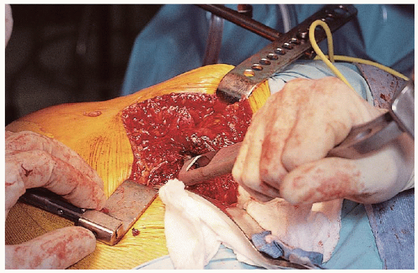
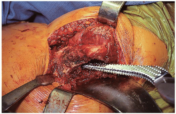
femoral canal is exposed by passing a broad, flat retractor under the
proximal femur. Remaining soft tissue is excised from the posterior and
lateral aspect of the femoral neck to the lesser trochanter. A box
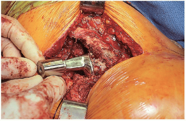
osteotome is used to open the proximal femur (Fig. 22-12).
If the greater trochanter overhangs the femoral canal, a small notch of
bone is removed from the greater trochanter to prevent reaming and
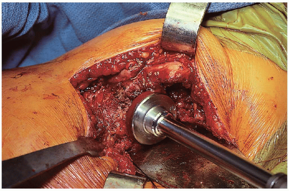
broaching in varus. A blunt T-handled starting reamer is placed down
the femoral canal in line with femur, directed toward the knee (Fig. 22-13). The femoral canal is reamed using hand or power reamers
,increasing in size incrementally until the appropriate-size reamer is
reached; the final reaming size depends on the size of the canal and on
the type of prosthesis selected.
 |
|
FIGURE 22-12. Use of a box osteotome to open the femoral canal.
|
 |
|
FIGURE 22-13. Placement of a blunt T-handled starting reamer down the femoral canal in line with femur, directed toward the knee.
|
The broach handle is held in the appropriate amount of anteversion
(approximately 15 degrees). With the leg positioned perpendicular to
the floor, it is easier to appreciate the amount of anteversion of the
broach. Excessive anteversion results in an
internal rotation deformity and increases the risk of anterior hip
dislocation; retroversion creates an external rotation deformity and
increases the risk of posterior dislocation. Inappropriate femoral
version can be avoided by careful observation of the distal femoral
axis during the femoral neck osteotomy, preparation of the femoral
canal, and insertion of the femoral prosthesis. When broaching
and reaming, it is important to resist the tendency to fall into varus
by providing a laterally directed force as the broaches and reamers are
advanced. The broach is periodically advanced and removed rather than
simply hammered straight down the canal; this technique reduces the
risk of iatrogenic femur fracture and helps avoid incarcerating the
broach in the femur. After the broach is fully seated to the level of
the femoral neck cut, the next size of broach is used, and the process
is repeated until the appropriate-size broach is fully impacted. The
final broach size is selected based on preoperative templating and,
more importantly, on the ease of insertion. A broach that advances too
easily is probably too small, and one that requires excessive force of
insertion increases the risk of femoral fracture. In cemented
applications, it is less important to achieve a tight interlock of the
broach with the femur, and there is no need to broach with excessive
force.
 |
|
FIGURE 22-14. Broaching of the femoral canal.
|
 |
|
FIGURE 22-15. Use of a calcar planar to even out the femoral neck.
|
With the broach in place, a trial head with the appropriate neck length
can be used to assess hip stability through a range of motion.
Stability in response to external rotation with the hip in full extension is assessed (Fig. 22-16), as well as stability of the hip in the position of sleep (i.e., flexion and adduction) (Fig. 22-17).
In the flexed position, the hip should be internally rotated to
determine the point at which the hip begins to lift out of the joint
(an angle of more than 30 degrees is preferred). With the hip in
neutral position, the amount of laxity to straight pull from the foot
should be tested (Fig. 22-18). Although this is
probably less important than other tests of stability, the push-pull
laxity should be minimal if an appropriate femoral neck length and
suction fit have been achieved. The distance from the level of the
lesser trochanter to the center of the head is measured with a ruler
and compared with the preoperative template. The center of the head
should also lie at roughly the level of the top of the trochanter.
Various neck lengths should be tested until stability is achieved.
 |
|
FIGURE 22-16. Checking stability in response to external rotation with the hip in full extension.
|
 |
|
FIGURE 22-17. Checking stability in the position of sleep (i.e., flexion and adduction).
|
 |
|
FIGURE 22-18. With the hip in neutral position, the amount of laxity to straight-pull from the foot is tested.
|
 |
|
FIGURE 22-19. Irrigation of the femoral canal.
|
measurements are made and stability testing completed, the hip is
dislocated, the broach and trial head are removed, and the canal is
brushed and irrigated (Fig. 22-19). If the
prosthesis is to be cemented, the canal is packed with a sponge while
the cement is prepared. A cement plug is inserted to the appropriate
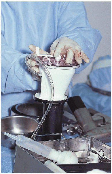
depth before cement insertion (Fig. 22-20). The cement is vacuum mixed and inserted in retrograde fashion using a cement gun and good pressurization technique (Figs. 22-21 and 22-22).
Alternatively, the cement can be hand packed into the femoral canal. In
some systems, a distal centralizer can be attached to the tip of the
prosthesis before insertion, which helps to prevent varus positioning.
Selection of the centralizer size is based on intraoperative
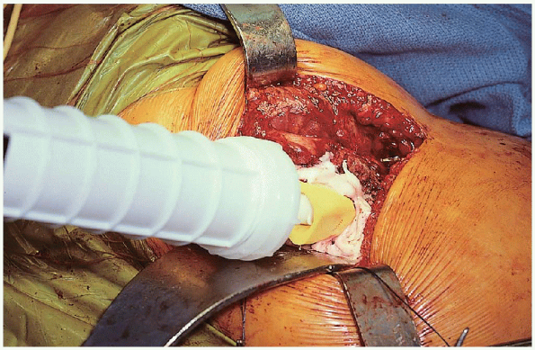
measurement of canal diameter. The prosthesis is
inserted using manual force and light taps with a mallet as it is fully seated to the level of the calcar cut (Fig. 22-23).
The position of the prosthesis should be maintained until the cement
hardens; any excess cement is removed using a curette before hardening.
Stability is then reassessed using head and neck trials. The final
prosthetic head with the appropriate neck length is lightly impacted
onto the clean and dry trunnion, and the hip is reduced after clearing
all soft tissue from the opening of the acetabulum. Hip stability is
once more assessed before wound closure. The short external rotators
and underlying capsule are reattached through drill holes to the
greater trochanter. The fascia lata is closed using interrupted
sutures, followed by skin closure. A Hemovac drain placed deep to the
fascia lata is preferred.
 |
|
FIGURE 22-20. Insertion of the cement restrictor.
|
 |
|
FIGURE 22-21. Vacuum mixing the cement.
|
 |
|
FIGURE 22-22. Insertion of the liquid cement down the femoral canal using a cement gun.
|
 |
|
FIGURE 22-23. Insertion of the prosthesis.
|
|
TABLE 22-1. HOSPITAL FOR JOINT DISEASES REHABILITATION PROTOCOL
|
||||||||||||||||
|---|---|---|---|---|---|---|---|---|---|---|---|---|---|---|---|---|
|
Results after hemiarthroplasty of the hip using a cemented femoral
prosthesis: a review of 109 cases with an average follow-up of 36
months. Mayo Clin Proc 1977;52:349-353.