
in the geriatric population with an impact that extends far beyond the
obvious orthopaedic injury into the domains of medicine,
rehabilitation, psychiatry, social work, and medical economics. Despite
improvements in patient care, including advances in operative technique
and implant technology, fractures of the proximal femur continue to
consume a major portion of national health care resources. The
increasing number of hip fractures that occur each year has made it
difficult to keep pace with this growing health care problem. With the
aging of the U.S. population, the annual number of hip fractures is
projected to double by the year 2050. This chapter describes closed
reduction and internal fixation of a displaced femoral neck fracture.
the region between the base of the femoral head and the
intertrochanteric line anteriorly and the intertrochanteric crest
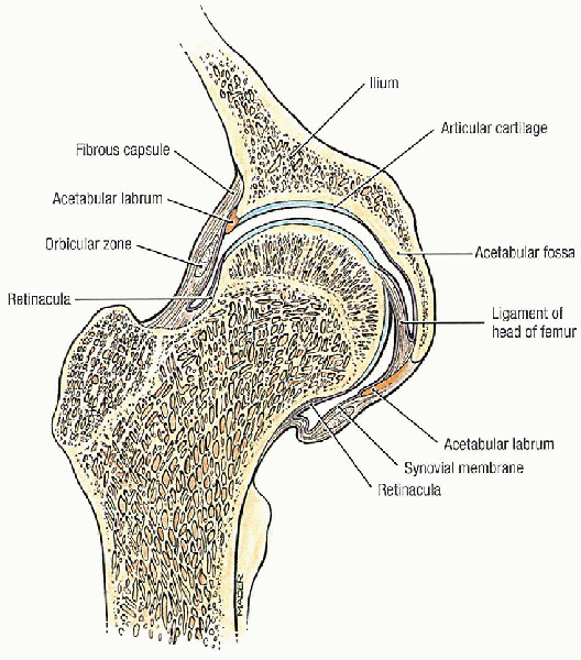
posteriorly (Fig. 23-1). The femoral neck forms
an angle with the femoral shaft ranging from 125 to 140 degrees in the
anteroposterior plane and 10 to 15 degrees (anteversion) in the lateral
plane. The cancellous bone of the femoral neck is characterized by
trabeculae organized into medial and lateral systems. The medial
trabecular system forms in response to the joint reaction force on the
femoral head; the epiphyseal plates are perpendicular to the medial
trabecular system. The lateral trabecular system resists the
compressive force on the femoral head resulting from contraction of the
abductor muscles (Fig. 21-1).
 |
|
FIGURE 21-1. Hip joint, coronal section. (From Agur AMR, Lee MJ. Grant’s atlas of anatomy, 10th ed. Philadelphia: Lippincott Williams & Wilkins, 1999, with permission.)
|
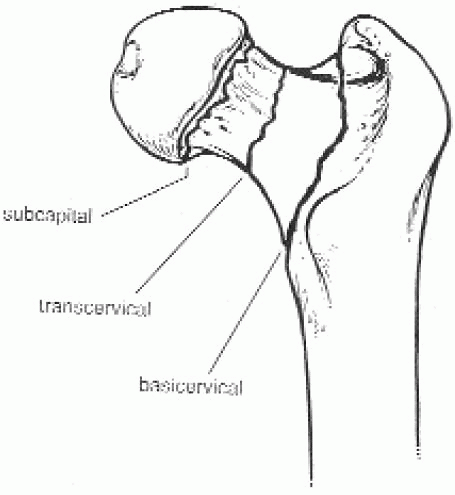
have been proposed. One such scheme is anatomically based and divides
the femoral neck into three regions: subcapital, transcervical, and
basocervical (Fig. 21-2). Most femoral neck
fractures are subcapital; transcervical femoral neck fractures are
usually the result of repetitive stresses. Because the subcapital and
transcervical regions are entirely intracapsular, fractures in these
regions exhibit different characteristics from those in the
basocervical region, which is extracapsular. Fractures that are
entirely intracapsular are at increased risk for osteonecrosis and
nonunion, sequelae that are uncommon after extracapsular fracture.
 |
|
FIGURE 21-2. The femoral neck region can be divided into three regions: subcapital, transcervical, and basocervical.
|
system, introduced by Garden in 1961, has four types based on the
degree of fracture displacement on the anteroposterior radiograph (Fig. 21-4):
 |
|
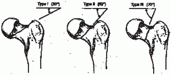
FIGURE 21-3.
The classification system proposed by Pauwels is based on the angle of inclination of the fracture line: type I, fracture line 30 degrees from the horizontal; type II, fracture line 50 degrees from the horizontal; and type III, fracture line 70 degrees from the horizontal. |
bony trabeculae of the inferior portion of the femoral neck remains
intact; includes “valgus-impacted” fractures
the fracture fragments, allowing the femoral head to rotate back to an
anatomic position; radiographically, the bony trabeculae of the femoral
head line up with the bony trabeculae of the acetabulum
best—approach is to classify femoral neck fractures as nondisplaced
(Garden types I and II) or displaced (Garden types III and IV). Further
differentiation can be difficult to establish radiographically and has
been shown to be subject to wide variability. The
nondisplaced/displaced scheme, which has the virtue of grouping
together fractures with similar treatment alternatives and similar
prognoses, is my preference for classifying femoral neck fractures.
the treatment of choice for almost all hip fractures, including those
involving the femoral neck. Impacted and nondisplaced femoral neck
fractures should undergo in situ internal
fixation using multiple cancellous lag screws. Whereas virtually all
patients with a nondisplaced femoral neck fracture should be treated by
internal fixation, such is not the case for displaced femoral neck
fractures.
replacement may be difficult. Although different investigators have
provided indications for primary prosthetic replacement based on
various criteria, I do not believe that specific indications
based
solely on patient care or fracture type is preferable or even possible.
Rather, each clinical situation should be assessed individually, with
careful consideration of patient factors (e.g., physiologic patient
age, associated medical problems) and fracture factors (e.g., bone
quality, amount of comminution, interval form injury to surgical
treatment) to arrive at a treatment decision. If successful, fracture
reduction (i.e., closed or open) and internal fixation provide the best
and most durable result after displaced femoral neck fracture.
 |
|
FIGURE 21-4.
The Garden classification is based on the degree of fracture displacement on the anteroposterior radiograph: type I, incomplete or impacted fracture in which the bony trabeculae of the inferior portion of the femoral neck remains intact (this category includes “valgus-impacted” fractures); type II, complete fracture without displacement of the fracture fragments; type III, complete fracture with partial displacement of the fracture fragments; and type IV, complete fracture with total displacement of the fracture fragments, allowing the femoral head to rotate back to an anatomic position. |
displaced femoral neck fracture and are relatively healthy, have
minimal fracture comminution, and can undergo surgery within 24 to 48
hours of injury should have an attempt at fracture reduction and
internal fixation; hemiarthroplasty is restricted to older, less
healthy, low-demand individuals. Elderly patients
with a displaced femoral neck fracture and multiple medical
comorbidities are best served by a single operation that is associated
with a low failure rate (i.e., prosthetic replacement)—particularly
when the presence of posterior femoral neck comminution substantially
increases the risk for healing complications.
strategy for treating displaced femoral neck fractures involves
internal fixation using multiple cannulated cancellous screws after
closed or open reduction for most patients with adequate bone density.
I treat this fracture as an urgent situation, with rapid medical
stabilization and surgical treatment within 24 hours of admission
whenever possible. Prosthetic replacement is reserved for those
physiologically older individuals in whom internal fixation is unlikely
to succeed: those with marked osteopenia or fracture comminution, or
both. Such patients tend to be older and have lower functional demands.
They may be unable to ambulate without assistive devices, and
associated medical problems often limit their life expectancy.
-
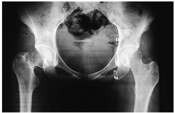
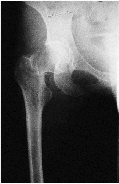
Anteroposterior view of the pelvis (Fig. 21-5)
-
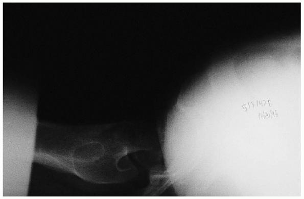
Anteroposterior and cross-table lateral view of the involved proximal femur (Figs. 21-6 and 21-7).
comminution of the proximal femur; a cross-table lateral view is
preferred to a frog lateral view because the latter requires abduction,
flexion, and external rotation of the affected lower extremity and
involves a risk of fracture displacement.
offsets the anteversion of the femoral neck and provides a true
anteroposterior view of the proximal femur. A second anteroposterior
view of the contralateral side can be used for preoperative planning.
in which the femoral head is posterior to the femoral shaft and the
distal fragment is externally rotated can be misinterpreted as an
intertrochanteric fracture. If the fracture pattern is misinterpreted,
the femoral neck fracture may be properly diagnosed only after the
anesthetized patient is placed on a fracture table and traction and
internal rotation have been applied. If prosthetic replacement is the
preferred procedure, the patient would have to be moved from the
fracture table to a flat table. This pitfall can be avoided by the use
of anteroposterior and cross-table lateral
radiographs when evaluating proximal femur fractures. If these
radiographs do not clarify the nature of the fracture pattern, a
radiograph taken with the extremity internally rotated should be taken.
 |
|
FIGURE 21-5. Anteroposterior view of the pelvis.
|
 |
|
FIGURE 21-6. Anteroposterior view of the involved proximal femur.
|
 |
|
FIGURE 21-7. Cross-table lateral view of the involved proximal femur.
|
 |
|
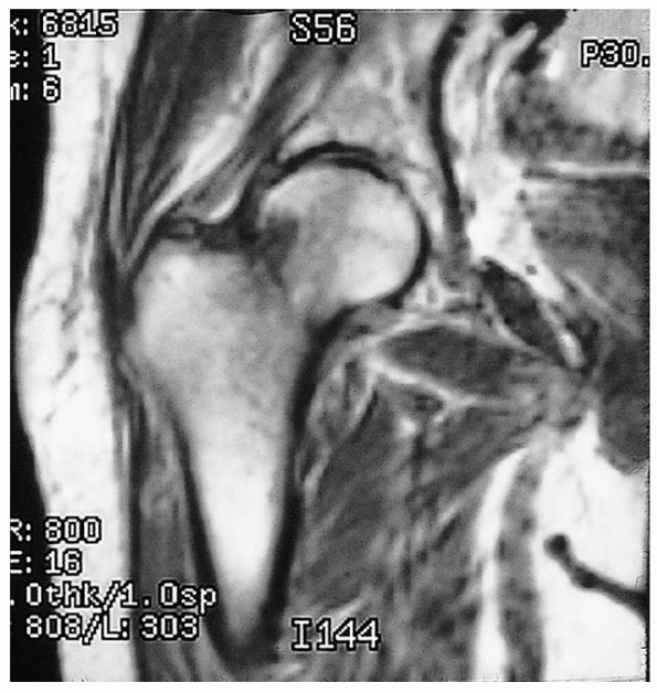
FIGURE 21-8. Magnetic resonance image shows a nondisplaced, right femoral neck fracture.
|
MRI has been shown to be at least as accurate as bone scanning in
identification of occult fractures of the hip and can be performed
within 24 hours of injury. MRI within 48 hours of fracture does not,
however, appear to be useful for assessing femoral head viability or
vascularity or predicting the development of osteonecrosis or healing
complications.
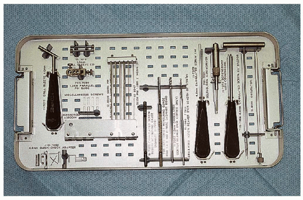
internal fixation of a displaced femoral neck fracture using multiple
cannulated cancellous screws include the following items (Fig. 21-9):
-
Fracture table that can be converted into
a flat operating table if closed reduction is unsuccessful and
prosthetic replacement becomes necessary -
Guide wires
-
Guide wire insertion device
-
Cannulated depth gauge
-
Cannulated reamer
-
Cannulated screwdriver
-
6.5-mm cannulated screws
 |
|
FIGURE 21-9. The cannulated screw instruments (left to right, selected mention):
4.0-mm drill sleeve, two 1.3-mm sleeves, parallel pin guide, pin guides, cannulated screw sleeve measuring gauge, direct measuring gauge, cannulated cortex reamer, 4.0-mm cannulated screw tap, self-holding screw driver, screwdriver with countersink, cannulated screw extractor, and obturator. |
patient is positioned supine on a fracture table that can be converted
into a flat operating table if closed reduction is unsuccessful and
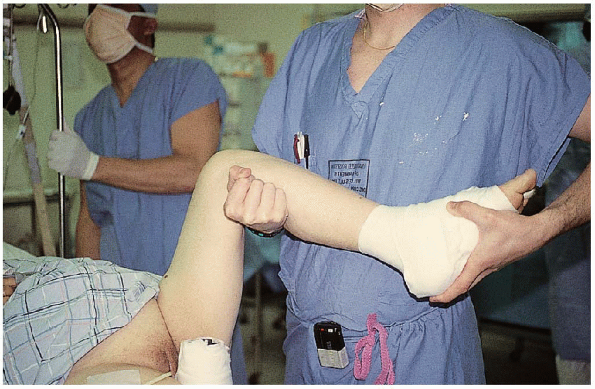
prosthetic replacement becomes necessary. Fracture reduction involves
90 degrees of flexion of the injured hip with external rotation to
disengage the fracture fragments (Fig. 21-10).
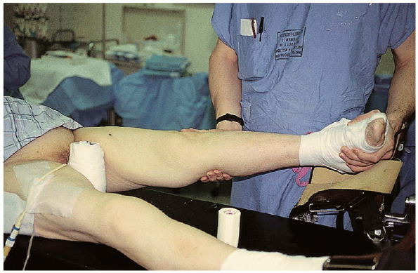
 Traction is applied as the leg is internally rotated and brought into full extension (Fig. 21-11). The maximum internal rotation of the injured lower extremity is then compared with the uninjured leg (Fig. 21-12);
if the two do not match, a successful reduction has most probably not
been obtained. The image intensifier, however, should be used for
anteroposterior and lateral assessment of the adequacy of the fracture
reduction.
properly assess the fracture reduction and guide implant insertion, the
surgeon must obtain unobstructed anteroposterior and cross-table
lateral radiographic images of the entire proximal femur (including the
hip joint) before making the skin incision.
Without visualization of the entire proximal femur, it is difficult to
assess the guide wire position as it is advanced into the femoral head.
Inappropriate screw length or location may result from inadequate
radiographic visualization. It may be necessary to alter the
positioning of the patient or image intensifier to obtain an
unobstructed cross-table lateral radiograph. In men, placement of the
scrotum away from the image beam can help delineate the femoral head on
the lateral radiographic view.
 |
|
FIGURE 21-10.
Fracture reduction involves 90 degrees of flexion of the injured hip with external rotation to disengage the fracture fragments. |
 |
|
FIGURE 21-11. Traction is applied as the leg is internally rotated and brought into full extension.
|
factor affecting the incidence of nonunion and osteonecrosis. To
determine the quality of fracture reduction, I measure the angle of the
femoral head on the true anteroposterior and cross-table lateral
radiographs. An acceptable reduction may have up to 15 degrees of
valgus angulation and less than 10 degrees of anterior or posterior
angulation. Some variation is acceptable, particularly when a valgus
reduction is obtained.
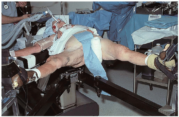
lower extremities are placed in foot holders. A padded perineal post is
placed in the ipsilateral groin; care must be taken that there is no
impingement of the labia or scrotum. It is
imperative that the genital area be inspected before fracture reduction
to verify that the scrotum is not incarcerated against the fracture
post and that the mucosa of the labia is not placed against—or even
directed toward—the fracture post, which can result in labial slough.
The uninvolved leg is then flexed, abducted, and externally rotated to
allow positioning of the image intensifier for a lateral view (Fig. 21-13). Alternatively, the contralateral extremity can be abducted with the hip and knee extended (Fig. 21-14); this maneuver, however, places greater pressure from the fracture post on the perineum.
ensure that the fracture has remained reduced and that nonobstructive
biplanar radiographic visualization of the entire proximal femur,
including the hip joint, is obtainable (Fig. 21-15).
The lower extremity, from the pelvis to the lower thigh, is then
prepared and draped. For this purpose, I prefer an isolation screen.
straight lateral incision is made from the base of the greater trochanter, extending 2 to 3 inches down the thigh (Fig. 21-16).
After incision of the skin and subcutaneous tissue, the iliotibial band
is divided longitudinally, with care taken to ensure that the deep
dissection remains posterior to the tensor fasciae latae muscle
proximally (Fig. 21-17).
The vastus lateralis fascia is divided longitudinally to expose its
muscle fibers and the posterior portion of the fascia elevated off the
underlying muscle down to the linea aspera. A Hohmann retractor is
placed under the vastus lateralis, just proximal to the insertion of
the gluteus maximus (Fig. 21-18).
The vastus lateralis is then elevated from the lateral femur in a
posterior-to-anterior direction, with care taken to identify and ligate
the perforating branches of the profunda femoral artery.
 |
|
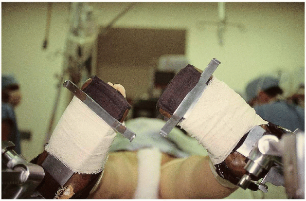
FIGURE 21-12.
The maximum internal rotation of the injured lower extremity is then compared with the uninjured leg; if the two do not match, a successful reduction has probably not been obtained. |
 |
|
FIGURE 21-13.
The uninvolved leg is then flexed, abducted, and externally rotated to allow positioning of the image intensifier for a lateral view. |
 |
|
FIGURE 21-14. Alternatively, the contralateral extremity can be abducted with the hip and knee extended.
|
 |
|
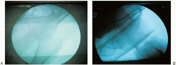
FIGURE 21-15. AP (A) and lateral (B)
radiographic confirmation that nonobstructive biplanar radiographic visualization of the entire proximal femur, including the hip joint, is obtainable. |
 |
|
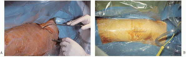
FIGURE 21-16. A straight, lateral incision is made from the base of the greater trochanter (A) and extends 2 to 3 inches down the thigh (B).
|
 |
|
FIGURE 21-17.
The iliotibial band is divided longitudinally, with care taken to ensure that the deep dissection remains posterior to the tensor fasciae latae muscle proximally. |
 |
|
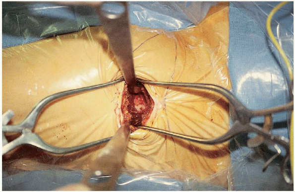
FIGURE 21-18.
A Hohmann retractor is placed under the vastus lateralis, just proximal to the insertion of the gluteus maximus. The vastus lateralis is then elevated from the lateral femur in a posterior-to-anterior direction, with care taken to identify and ligate the perforating branches of the profunda femoral artery. |
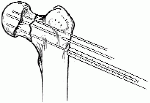
guide wires are inserted into the femoral neck and head under image
intensification. A guide wire can be placed anterior to the femoral
neck to estimate femoral neck anteversion, but I find this is
unnecessary. The guide wires should all be parallel and oriented in an
inverted triangular configuration, with one wire inferior and two wires
superior; this orientation provides the most mechanically secure
fracture fixation (Fig. 21-19). The guide wires
can be inserted using an insertion apparatus or a freehand technique; I
prefer a freehand technique. The inferior wire is placed adjacent to
the inferior neck cortex to resist varus displacement,
while one of the two superior wires is adjacent to the posterior femoral cortex to resist posterior displacement. These guide wires should be spaced apart to maximize fixation stability and inserted into the dense subchondral bone. Acommon pitfall during cancellous lag screw insertion is to place the
first guide wire or screw in the middle of the femoral neck and head,
making it difficult to insert the remaining screws; this may result in
a mechanically weaker configuration in which the screws are too close
to one another.
 |
|
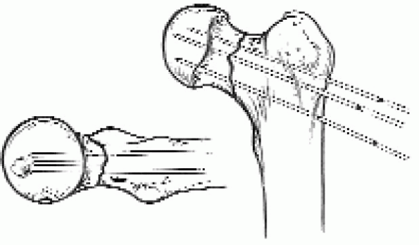
FIGURE 21-19.
Three guide wires are inserted into the femoral neck and head under image intensification. The guide wires should all be parallel and oriented in an inverted triangular configuration, with one wire inferior and two wires superior. This orientation provides the most mechanically secure fracture fixation. |
 |
|
FIGURE 21-20. After the guide wire positions have been set, the screw lengths are determined.
|
screw insertion through the cortical subtrochanteric region; this
creates a stress riser effect, increasing the risk for subsequent
fracture. To minimize the stress riser effect, the cancellous screws
should be inserted proximal to the lesser trochanter in the cancellous
bone of the metaphyseal region.
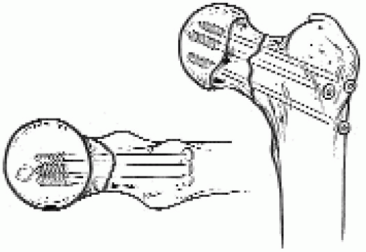
The screws should lie in the dense subchondral bone for optimal
fixation, and the threads should completely cross the fracture site.
The outer cortex of the proximal femur is then reamed and the screws
inserted (Fig. 21-21).
There is no need to ream the entire screw tract; this can result in
loss of the guide wire during reamer removal. Good-quality radiographs
are necessary to confirm proper placement of the screws, including
rotation of the proximal femur under fluoroscopy to detect possible
intraarticular screw penetration. After screw insertion, any traction
is released and the screws retightened.
osteonecrosis, I usually perform a capsulotomy at surgery; the
capsulotomy is performed under image intensification using a scalpel
directed along the anterior femoral neck (Fig. 21-22). The wound is closed in layers over suction drains.
 |
|
FIGURE 21-21. The outer cortex of the proximal femur is then reamed and the screws inserted.
|
 |
|
FIGURE 21-22.
Because capsular distention with increased intracapsular pressure has been implicated as a possible cause of posttraumatic osteonecrosis, I usually perform a capsulotomy at surgery. The capsulotomy is performed under image intensification using a scalpel directed along the anterior femoral neck. |
fluoroscopically assessed before wound closure. It has been
demonstrated that femoral head penetration can be missed on
anteroposterior and cross-table lateral radiographic evaluation.
Accurate evaluation of screw position involves rotating the
radiographic beam under fluoroscopy. This continuous fluoroscopic
evaluation while the beam is passed from an anteroposterior to lateral
position is helpful to detect femoral head penetration.
|
TABLE 21-1. HOSPITAL FOR JOINT DISEASES REHABILITATION PROTOCOL
|
||||||||||||||||
|---|---|---|---|---|---|---|---|---|---|---|---|---|---|---|---|---|
|