
in the elderly. These injuries impact far beyond the obvious
orthopaedic injury into the domains of medicine, rehabilitation,
psychiatry, social work, and medical economics. The significance of hip
fractures in the elderly becomes even more important as the number of
geriatric hip fractures occurring each year increases in the face of
increasing pressure for health care cost containment at all levels of
our health care system. This chapter discusses the use of a sliding hip
screw for stabilization of an intertrochanteric hip fracture.
The cancellous bone in this intertrochanteric region is well
vascularized. Surgeons rarely encounter the problems of nonunion and
osteonecrosis that can complicate intracapsular fractures.
 |
|
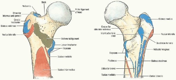
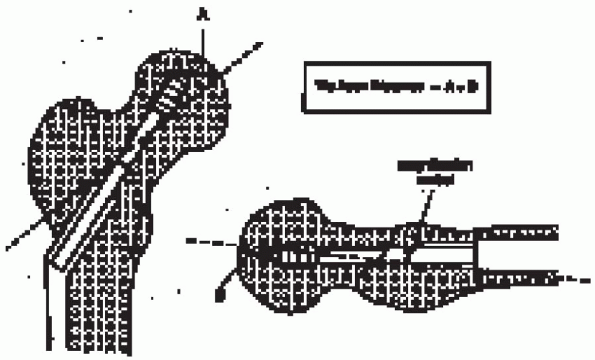
FIGURE 23-1. Muscle attachments of the proximal femur. (A) Proximal femur, anterior view. (B) Proximal femur, posterior view. (From Agur AMR, Lee MJ. Grant’s atlas of anatomy, 10th ed. Philadelphia: Lippincott Williams & Wilkins, 1999, with permission.)
|
Unstable fracture patterns also include intertrochanteric fractures
with subtrochanteric extension and those with a reverse obliquity
pattern.
surgery. Nonoperative management is appropriate only in selected
patients who are nonambulatory and who experience minimal discomfort
from their injury, or patients who are medically too sick to undergo
surgery.
 |
|
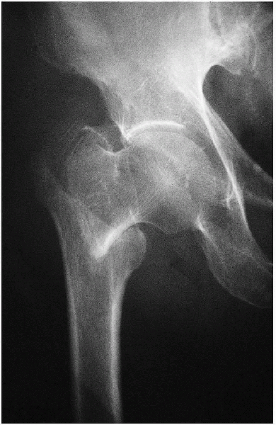
FIGURE 23-2. Stable fracture. Notice that the posteromedial cortex remains intact.
|
-
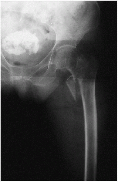
Anteroposterior view of the pelvis (Fig. 23-4)
-
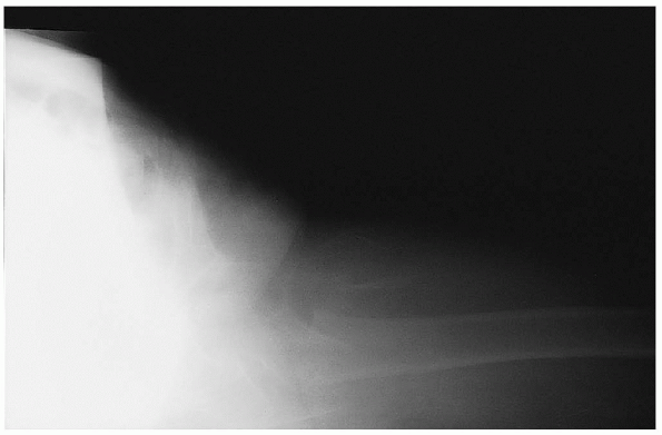
Anteroposterior and cross-table lateral view of the involved proximal femur (Figs. 23-5 and 23-6).
comminution of the proximal femur; a cross-table lateral is preferred
to a frog lateral view because the latter requires abduction, flexion,
and external rotation of the affected lower extremity and involves a
risk of fracture displacement.
offsets the anteversion of the femoral neck and provides a true
anteroposterior of the proximal femur. A second anteroposterior view of
the contralateral side can be used for preoperative planning.
 |
|
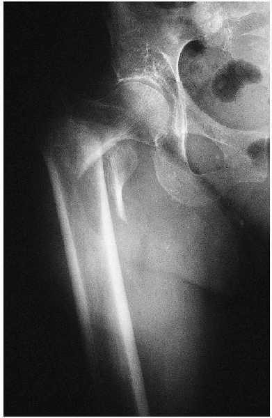
FIGURE 23-3. Unstable fracture. Notice the greater comminution of the posteromedial cortex.
|
 |
|
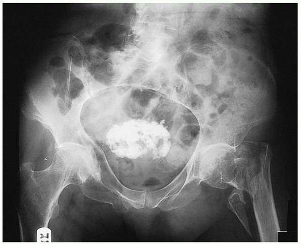
FIGURE 23-4. Standard radiographic view: anteroposterior view of the pelvis, showing a left intertrochantene hip fracture.
|
 |
|
FIGURE 23-5. Standard radiographic view: anteroposterior view of the involved proximal femur.
|
fracture is suspected but not apparent on standard radiographs. MRI has
been shown to be at least as accurate as bone scanning in
identification of occult fractures of the hip and can be performed
within 24 hours of injury. MRI within 48 hours of fracture does not,
however, appear to be useful for assessing femoral head viability or
vascularity or for predicting the development of osteonecrosis or
healing complications.
 |
|
FIGURE 23-6. Standard radiographic view: cross-table lateral view of the involved proximal femur.
|
-
Guide pins
-
Angle guides
-
Depth gauge
-
Adjustable reamer
-
Guide wire repositioner
-
Tap
-
Lag screw extenders
-
Insertion handle
-
3.5-mm drill
-
Drill guide
-
Screwdriver
with both lower extremities resting in padded foot holders. A padded
perineal post is placed in the ipsilateral groin, with care taken that
there is no impingement of the labia or scrotum. In female patients, it
is important to verify that the mucosa of the labia is not everted
against the perineal post.
fractures can be reduced using gentle longitudinal traction with the
leg externally rotated followed by internal rotation. The uninvolved
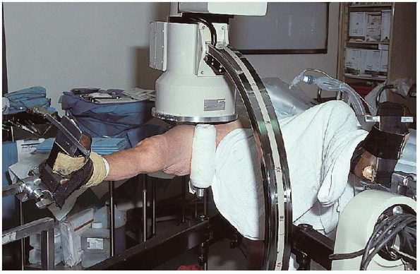
leg is then flexed, abducted, and externally rotated to allow
positioning of the image intensifier for a lateral view (Fig. 23-8).
Alternatively, the contralateral extremity can be abducted with the hip
and knee extended; this maneuver, however, places greater post pressure
on the perineum.
the patient, and the surgeon must be certain that nonobstructive
biplanar radiographic visualization of the entire proximal femur,
including the hip joint, is obtainable. Inadequate
visualization of the entire proximal femur can result in inappropriate
lag screw length or positioning. The surgeon must be prepared to deal
with residual varus angulation, posterior sag, or malrotation. Fracture
reduction with varus angulation or posterior sag results in difficulty
centering the lag screw in the femoral neck and head. Varus angulation
can usually be corrected by placing additional traction on the lower
extremity to disengage the
fracture fragments, followed by repeat fracture
reduction. Occasionally, the lower extremity must be abducted to
correct a varus malreduction. If residual varus remains, the surgeon
should check the position of the fracture fragments on the lateral
radiographic view, because posterior sag may prevent adequate fracture
reduction. In this situation, traction should be released and the
fracture manipulated to disengage the fragments. Posterior sag requires
manual correction using a crutch, bone hook, or periosteal elevator. If
unrecognized, posterior sag results in guide pin positioning in the
anterior femoral neck and posterior femoral head. I rotate the lower
extremity under fluoroscopic control to determine whether the fracture
fragments move as a single unit. In patients in whom the femoral shaft
moves independently from the proximal fragment, excessive internal
rotation of the leg is avoided. Instead, the lower extremity is placed
in neutral or slight external rotation.
 |
|
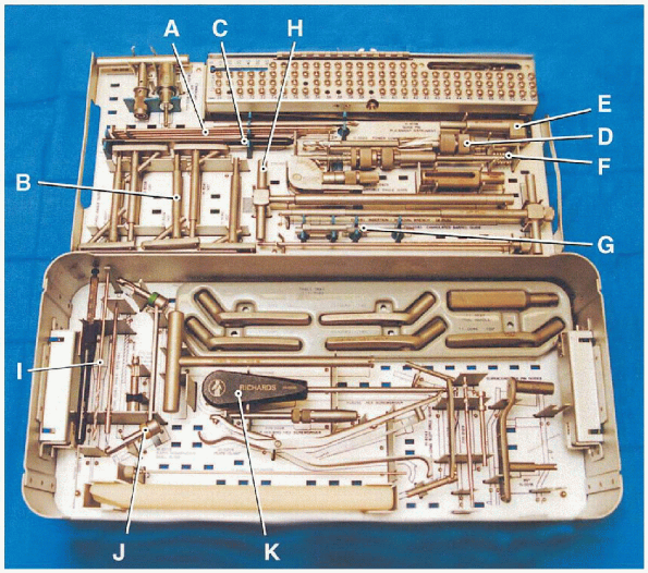
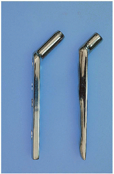
FIGURE 23-7. The basic instruments necessary for insertion of a sliding hip screw: guide pins (A), angle guides (B), depth gauge (C), adjustable reamer (D), guide wire repositioner (E), tap (F), lag screw extenders (G), insertion handle (H), 3.5-mm drill (I), drill guide (J), and screwdriver (K).
|
 |
|
FIGURE 23-8.
Patient positioning. The uninvolved leg is flexed, abducted, and externally rotated to allow positioning of the image intensifier. |
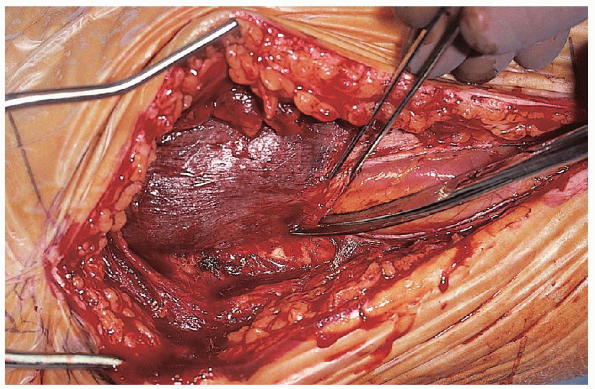
and the iliotibial band is incised in line with its fibers, with care
taken to remain posterior to the tensor fasciae latae muscle (Fig. 23-10).
This exposes the vastus lateralis and its covering fascia. Rather than
using a muscle-splitting approach through the vastus lateralis, I
prefer to incise the fascia of the vastus lateralis and reflect the
muscle from the intermuscular septum.  Care should be taken to identify and ligate the perforators from the profunda femoral artery (Fig. 23-11) ;
if cut, they may retract posteriorly through the intermuscular septum,
making them difficult to control. The lateral aspect of the proximal
femur is cleared of soft tissue using a periosteal elevator, and the
vastus lateralis is retracted anterior with a Hohmann retractor.
 |
|
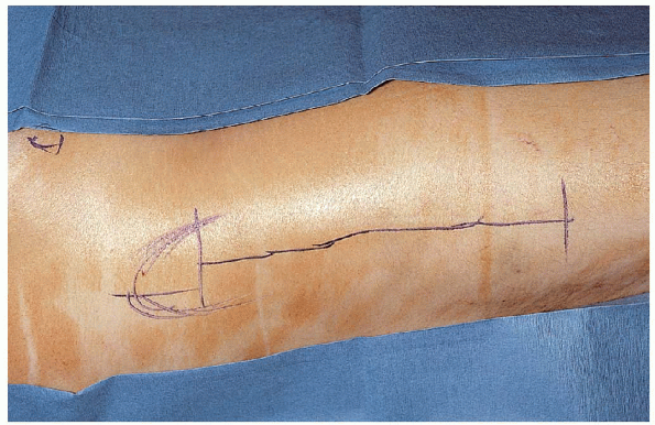
FIGURE 23-9. In this approach, a straight, 8- to 10-cm, lateral incision starts at the base of the greater trochanter and extends distally.
|
 |
|
FIGURE 23-10.
The incision is deepened through subcutaneous tissue, and the iliotibial band is incised in line with its fibers, with care taken to remain posterior to the tensor fasciae latae muscle. |
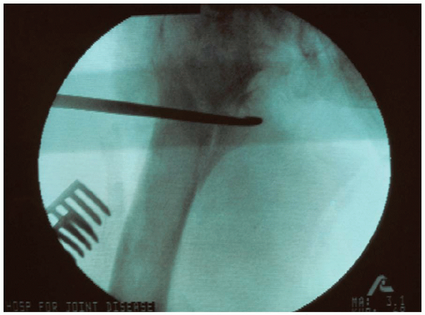
image intensification, a starting point is identified on the lateral
cortex of the proximal femur. This is usually at the level of the
lesser trochanter, centered between the anterior and posterior cortical
margins. A drill hole is made and a guide pin inserted into the femoral
neck and head under image intensification using the 135-degree guide (Fig. 23-12).
A guide pin can be placed anterior to the femoral neck to estimate
femoral neck anteversion, although I find this unnecessary. The
position of the guide pin is adjusted until it lies in the center of
the femoral head and neck on the anteroposterior and lateral planes.
 |
|
FIGURE 23-11. Care should be taken to identify and ligate the perforators from the profunda femoral artery.
|
 |
|
FIGURE 23-12.
A starting point is identified on the lateral cortex of the proximal femur, usually at the level of the lesser trochanter, centered between the anterior and posterior cortical margins. A drill hole is made and a guide pin inserted into the femoral neck and head under image intensification using the 135-degree guide. |
distance (TAD) to determine lag screw position within the femoral head.
This measurement, expressed in millimeters, is the sum of the distances
from the tip of the lag screw to the apex of the femoral head on the
anteroposterior and lateral radiographic views (after controlling for
radiographic
magnification).
Peripheral malposition of the lag screw is not differentiated from
shallow lag screw positioning; only the actual distance from the tip of
the lag screw to the apex of the femoral head is considered. Based on
evaluation of a series of patients, he recommended that, if guide pin
location yields a TAD of more than 25 mm, the surgeon should reassess
the fracture reduction and reposition the guide pin (Fig. 23-13).
 |
|
FIGURE 23-13. The tip-apex distance (TAD) is used to determine lag screw position within the femoral head.
|
the guide pin cannot be positioned appropriately in the femoral head
and neck, the fracture reduction and plate angle should be reassessed,
particularly for residual varus and posterior sag. Occasionally, a 130-
or 140-degree insertion is needed to optimize lag screw position.
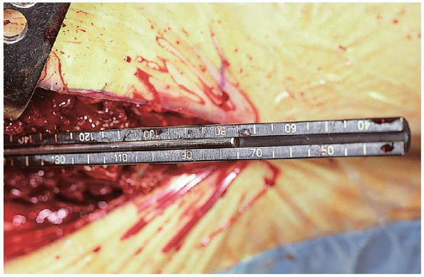
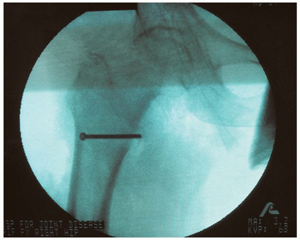
When the guide pin is confirmed to be in the desired position, it is
advanced to the level of the subchondral bone, and the length of the
lag screw is determined (Fig. 23-14).
In stable intertrochanteric fractures, significant fracture impaction
is not anticipated, and a screw length is chosen that maximizes
screw-barrel engagement, allows for about 5 mm of impaction, and lies
within 1 cm of the subchondral bone. For example, if the guide pin
measures 100 mm to the subchondral bone, a 90-mm-long lag screw may be
selected; once fully seated 5 mm from the subchondral bone, the lag
screw would be inset 5 mm into the plate barrel.
 |
|
FIGURE 23-14.
When the guide pin is in the desired position, it is advanced to the level of the subchondral bone, and the length of the lag screw is determined. |
 |
|
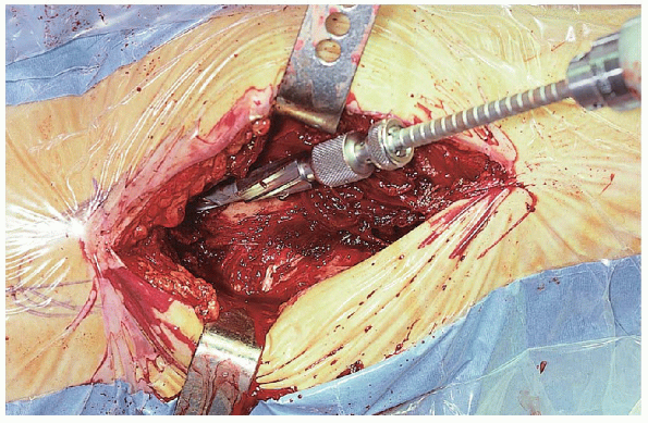
FIGURE 23-15. Reaming of the femoral neck and head over the guide pin is performed to the desired final position of the lag screw.
|
of the femoral neck and head over the guide pin is performed under
image intensification to the desired final position of the lag screw (Fig. 23-15). The
position of the guide pin during reaming must be monitored to detect
possible binding of the guide pin within the reamer, which may result
in guide pin advancement and femoral head penetration. The position of
the guide pin may be lost during reamer removal; the guide pin can be
replaced using a guide pin repositioner available in many sliding hip
screw sets or by a free lag screw inserted backward into the reaming
channel.
The reamed tract is tapped, even in elderly patients, to prevent femoral head rotation during lag screw insertion. The lagscrew is then inserted to within 1 cm of the subchondral bone.
 |
|
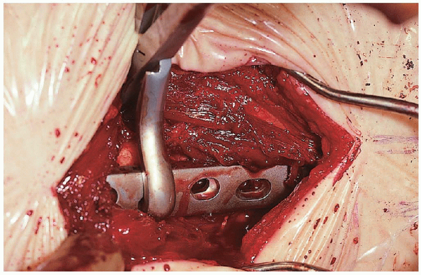
FIGURE 23-16.
When the proper position of the lag screw within the femoral head has ben confirmed, a three- or fourhole, 135-degree side plate is placed over the screw. |
 |
|
FIGURE 23-17. A standard (long-barrel) plate is used for most intertrochanteric fractures.
|
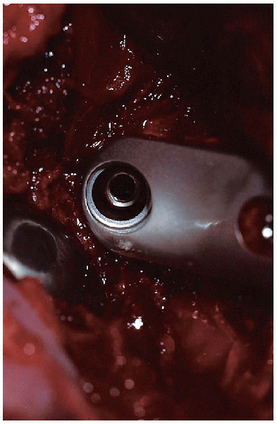
the proper position of the lag screw within the femoral head has been
confirmed, a three- or four-hole, 135-degree side plate is placed over
the screw (Fig. 23-16).
I routinely use a three-hole plate for fixation of stable and unstable
intertrochanteric fractures. I prefer the use of a “keyed” sliding hip
screw system. In a keyed system, the lag screw is captured within the
plate barrel such that the screw can slide along the barrel but cannot
rotate. Use of a keyed sliding hip screw system requires that the lag
screw be oriented so that the plate can be properly positioned along
the femoral shaft.
The longer barrel maximizes the amount of screw-barrel engagement and
minimizes the likelihood of the lag screw “jamming” within the plate
barrel. However, a short-barrel plate is used if a lag screw of less
than 85 mm has been inserted. This helps to prevent postoperative
impaction that exceeds the sliding capacity of the device. The
minimum amount of available screw-barrel slide necessary to reduce the
risk of fixation failure with use of a sliding hip screw has been
estimated to be 10 mm.
plate is loosely clamped to the femoral shaft and the fracture impacted
by releasing the traction on the extremity and gently displacing the
femoral shaft toward the proximal fragment. The plate clamp is then
tightened, and the fracture position is reassessed. This impaction
maneuver enhances fracture stability and helps prevent fracture
distraction that may result in excessive postoperative screw-barrel
slide.
The plate-holding screws are then inserted. The need for a compression screw is determined by direct visualization of the lag screw within the plate barrel (Fig. 23-18); a compression screw is inserted if there is risk of postoperative screw-barrel disengagement.to achieve fracture impaction. A compression screw is not used
routinely because it is an added expense and because the compression
screw often loosens (even during uneventful fracture healing) and can
become a source of lateral thigh pain.
intertrochanteric fractures are characterized by loss of the
posteromedial buttress. Another type of unstable intertrochanteric
fracture is the reverse obliquity pattern, which begins just proximal
to the lesser trochanter and extends laterally and distally with an
oblique orientation.
posteromedial comminution is similar to that described for stable
fracture patterns in the preceding section: anatomic fracture alignment
followed by internal fixation using a sliding hip screw. In older
patients, the posteromedial fragment is
usually
ignored. In younger patients, an attempt should be made to stabilize
large posteromedial fragments in a nearanatomic position to prevent
excessive screw-barrel slide, which would result in limb shortening. Reduction
and stabilization of the posteromedial fragment can be performed before
or after lag screw and side plate application. I prefer the former,
because this method facilitates anatomic fracture reduction of the
posteromedial fragment. If the main fracture fragments are reduced and
stabilized primarily, it may be impossible to reduce the posteromedial
fragment anatomically.
 |
|
FIGURE 23-18.
Insertion of the plate-holding screws. The need for compression is determined by direct visualization of the lag screw within the plate barrel. |
 |
|
FIGURE 23-19.
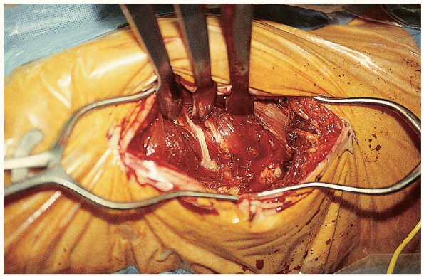
In this procedure for treating unstable fractures, the posteromedial fragment can be reduced using a bone hook and can be provisionally stabilized using a Verbrugge or standard reduction clamp. |
 |
|
FIGURE 23-20.
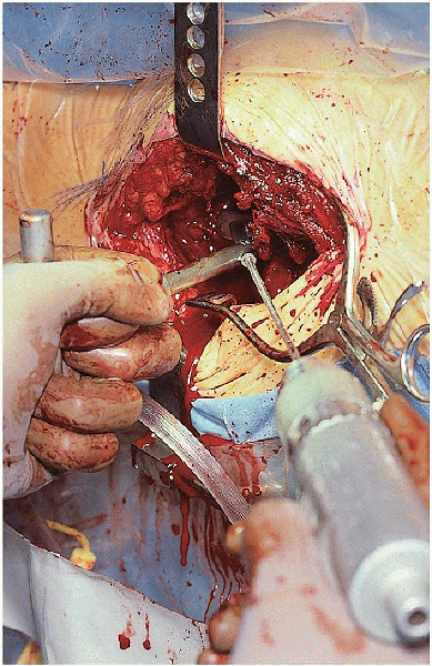
Definitive fracture fixation involves the use of one or more cerclage wires or one or more lag screws directed from anterolateral to posteromedial aspects. |
|
TABLE 23-1. HOSPITAL FOR JOINT DISEASES REHABILITATION PROTOCOL
|
||||||||||||||||
|---|---|---|---|---|---|---|---|---|---|---|---|---|---|---|---|---|
|
should be no traction on the lower extremity; because the iliopsoas is
attached to the lesser trochanter, traction results in proximal
migration of the posteromedial fragment. The extremity is externally
rotated to better expose the posteromedial area of the femoral shaft.
The posteromedial fragment can be reduced using a bone hook and
provisionally stabilized using a Verbrugge or standard reduction clamp (Fig. 23-19).
Definitive fracture fixation involves use of one or more cerclage wires
or one or more lag screws directed from anterolateral to posteromedial
aspects (Fig. 23-20). These screws cannot be
inserted through the proximal hole of the plate. Proper angulation
cannot be achieved because of the limitations of the screw hole and its
position distal to the involved area. After the posteromedial fragment
is stabilized, traction is placed on the lower extremity, and the head
and neck fragment reduced. The sliding hip screw is then inserted as
previously described.
Gamma nail vs compression screw for trochanteric femoral fractures: 15
reoperations in a prospective, randomized study of 378 patients. Acta Orthop Scand 1994;65:127-130.
Unstable intertrochanteric fracture of the femur: a prospective
randomized study comparing anatomical reduction and medial displacement
osteotomy. J Bone Joint Surg Br 1993;75:445-447.
Treatment of unstable peritrochanteric fractures in elderly patients
with a compression hip screw or with the Vandeputte (VDP)
endoprosthesis: a prospective randomized study. J Orthop Trauma 1995;9: 292-297.