
plates and screws may be carried out for any fracture of the tibia in
which soft-tissue conditions are satisfactory. Although intramedullary
interlocking nails have become popular for the treatment of many
tibial-shaft fractures, plating remains a viable alternative (1).
Compared with an intramedullary implant, plating of the tibia requires
greater attention to the condition of the soft tissues, more
preoperative planning, and greater attention to surgical detail during
the procedure.
tibial-shaft fractures are the presence of compartment syndrome,
neurovascular injury, compromised medullary canal, or compromised
access to the medullary canal due to associated injury (2,3).
conditions: polytraumatized patients, open fractures, late loss of
reduction with closed treatment, segmental injury, fractures that
extend into either the knee or ankle joint, fractures of the proximal
and distal one third of the shaft, and fractures in patients whose
livelihood or recreational habits demand perfect restoration of length
and rotation (2,3). Certain fracture patterns may be better
anatomically restored by plating. For example, a distal, spiral,
oblique fracture or a simple oblique fracture with a relatively steep
fracture plane may be best treated with a plate as will fractures that
extend to the ankle joint.
include isolated, displaced, diaphyseal fractures, which may be better
treated with a locked intramedullary nail. Grossly contaminated open
fractures, which will require serial débridements, are best treated
with an external fixator.
time of injury and at the time of surgery is essential because its
condition influences the timing of the surgical procedure. The Tscherne
classification may be helpful in evaluating and assessing the
soft-tissue
injury
associated with a particular fracture pattern (4). In patients whose
soft tissue does not permit early internal fixation because of
swelling, abrasions, or blisters, may benefit from a 10 to 14 day
waiting period. The skin should have a very fine wrinkled texture or
appearance before plate osteosynthesis is undertaken.
is well suited to plate fixation. It has a large subcutaneous surface
that may be used for stabilization without the muscles being stripped
(5). Because no muscle needs to be stripped from it, the medial face of
the tibia is, in fact, an ideal plating surface. Most of the poor
results and subsequent criticisms of tibial plating were due to poor
soft-tissue technique, inappropriate implant use, and poor reductions.
radiographic pattern of the fracture is carried out immediately.
Attention to the neurovascular status as well as the status of the
muscle compartments is mandatory. The presence of soft-tissue
contusion, skin necrosis, swelling, compartment syndrome, skin
abrasion, or any wounds is carefully documented. Anteroposterior (AP)
and lateral views of the tibia, to include both knee and ankle joint,
must be obtained (Fig. 28.1).
on the condition of the soft tissues. ORIF of the tibia should only be
carried out when satisfactory skin and wound conditions permit a
tension-free soft-tissue closure at the conclusion of the procedure. If
these conditions do not exist, then internal fixation should be
postponed. The extremity should be splinted, casted, or a temporary,
spanning, external fixator applied until more favorable conditions
exist. If surgery is delayed, the limb should be elevated to help
resolve any swelling. Necrotic soft tissue should be well demarcated
and excised at the time of surgery. A gastrocnemius, rotational, muscle
flap will be required for proximal tibia fractures. In the distal
tibia, a free tissue transfer or a fasciocutaneous rotational flap may
be needed. When satisfactory soft-tissue conditions are present, the
procedure may be carried out with a well-conceived preoperative plan
and a surgical tactic.
should be obtained. If the fracture is complex or if deformity is
significant, an AP and lateral radiograph of the unaffected side or an
AP and lateral radiograph of the affected extremity in traction may
help the surgeon better conceptualize the fracture pattern. The
preoperative drawings, which need not be of artistic quality, should be
fashioned so that a step-by-step procedure from start to finish is
outlined in a simple fashion (Fig. 28.2).
Because the preoperative plans are displayed in the operating room at
the time of the surgery, they should list any equipment that might be
required. The steps of the procedure are indicated directly on the
preoperative plan in numeric order.
be AO/ASIF screws and plates including the limited-contact dynamic
compression (LCDC) plate with combination holes (Synthes, Paoli, PA).
Basic instruments, an AO drill, bone forceps, and associated small
soft-tissue retractors and elevators are also required.
bone quality is poor due to osteoporosis or when the distal fragment is
relatively short. Using a locked construct will allow the creation of a
fixed angle device, and when applied to one or the other major
fragments, it will allow the plate to be used to facilitate the
reduction (i.e., indirect technique). Precontoured plates are available
for some fracture patterns and applications. A locked plate must be
accurately contoured if it is to be used as a reduction tool because a
locked screw will not pull the plate and bone together. In some
instances, a more stable construct can be created with locking screws.
Preoperative planning may be more difficult because of the uncertainty
of the locked screw projections after plate contouring.
locking screws is assumed. A complete discussion of locking technique
is beyond the scope of this chapter.
 |
|
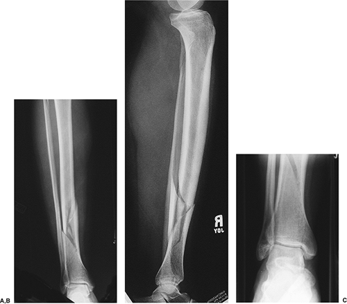
Figure 28.1. AP (A) and lateral (B)
radiographs of the tibia and fibula showing an oblique fracture pattern with butterfly fragments that are mildly displaced. Nondisplaced fracture lines extend toward the ankle joint. C. A nondisplaced, medial, malleolar fracture is shown. |
preoperative plan has been established, the procedure may be initiated (Fig. 28.3).
Intraoperative findings (such as nondisplaced fracture lines or
unrecognized comminution) may contradict the preoperative plan for
trauma reconstruction (such as for an osteotomy). In such cases, the
order of the preoperative plan may need to be altered.
regular operating-room table. A tourniquet is not required for the
procedure but may be used if desired. Use of either general or spinal
anesthesia is satisfactory. The entire leg is prepped from the toes to
the groin. Prophylactic intravenous antibiotics, usually a single
preoperative dose of cephalosporin, is
recommended.
The location and length of the incision is drawn on the skin before
application of an adhesive iodine-impregnated drape (Fig. 28.4). I prefer to carry out the procedure in the seated position at the foot of the table with the surgical assistant also seated.
 |
|
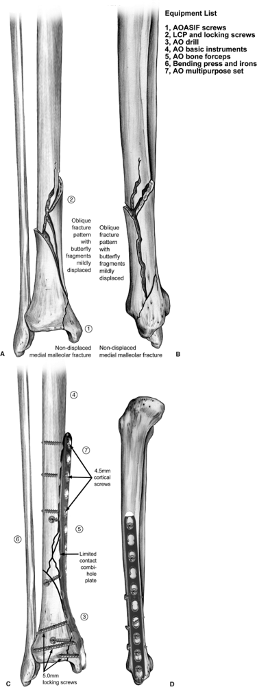
Figure 28.2. A–D.
AP and lateral preoperative drawings illustrate the fracture pattern and subsequent definitive fixation. This is helpful in selecting a plate of proper length to contour. The plate may be used to achieve reduction followed by lag screw fixation or vice versa. The articulating tension device may be used to load the construct if the pattern allows. Preoperative plan: Step 1: Indicate joint axis. Step 2: Reduce and secure butterfly fragments. Step 3: Precontour plate and apply to distal fragment. Step 4: Not shown; push/pull screw may be inserted proximally. Step 5: Adjust reduction. Step 6: Additional lag screws if necessary. Step 7: Additional plate screws to balance fixation. |
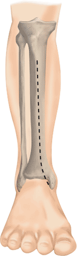
(1). The incision is curved gently at its distal portion at the level
of the metaphyseal flare in the supramalleolar region. A long surgical
incision is preferred because it allows satisfactory exposure of the
tibia and allows the surgeon to avoid unnecessary, vigorous, skin
retraction, particularly on the medial skin flap (Fig. 28.6A)
(6). The saphenous vein or nerves need not be sacrificed in the distal
portion of the incision because the plate may be placed beneath these
structures, leaving them completely intact (see Fig. 28.6B). They should be dissected only enough to allow passage
of the plate beneath them. In addition, the sheath of the tibialis anterior tendon need not be entered.
 |
|
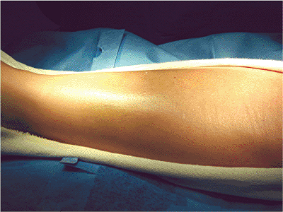
Figure 28.3.
The condition of the skin is ascertained before undertaking ORIF. In this case, no ecchymosis or fracture blisters are found. A minimal amount of edema is present and a fine wrinkle pattern can be noted on the skin 10 days after the initial injury. |
 |
|
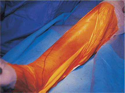
Figure 28.4.
Planned surgical incision is indicated on the skin with a marker to assist in the surgical approach as well as wound closure. The operative area is draped with adhesive iodine. |
 |
|
Figure 28.5.
The surgical incision is anterior and curvilinear. It begins 1 cm lateral to the tibial crest and curves medially in the distal portion. |
 |
|
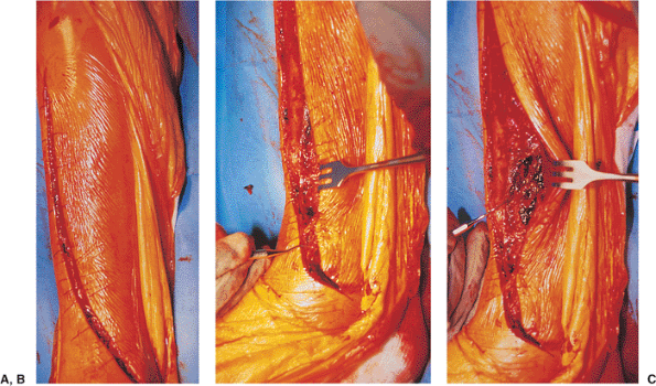
Figure 28.6. A. The surgical incision is carried through the skin and subcutaneous tissue. B.
The small dental instrument indicates the location of the distal saphenous structures, which are preserved during the surgical approach and the procedure. C. The small dental instrument indicates the presence of fracture hematoma, which is removed for exposure of the fracture. |
direction just enough to allow exposure of the posteromedial border of
the tibia and the butterfly fragment, which are seen after removal of
the fracture hematoma. The dissection remains extraperiosteal. The
periosteum is frequently noted to be stripped at the fracture edges as
a result of fracture displacement. If any additional periosteal
elevation is necessary to evaluate reduction, then not more than 1 or 2
mm at the immediate fracture edge should be elevated. The remainder of
the procedure should be carried out entirely extraperiosteally (Fig. 28.7) (1).
 |
|
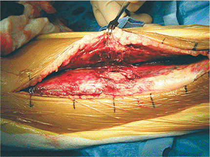
Figure 28.7.
After evacuation of the fracture hematoma, the fracture, including the minimally displaced posteromedial butterfly, can be seen. The edges of the fracture are compared to the surrounding hemorrhagic periosteum and are noted to be white. This indicates the amount of periosteum that was stripped by the injury itself. The stripping done by the injury allows for sufficient visualization of the fracture edges and subsequent reduction. No further periosteal stripping should be necessary for reduction and fixation of this fracture. The periosteum is hemorrhagic because of the injury and also because no tourniquet is used. |
 |
|
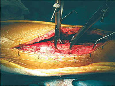
Figure 28.8.
The posteromedial butterfly is directly reduced with bone forceps. Even though the butterfly is directly reduced, the bone forceps is applied extraperiosteally; no soft-tissue stripping is necessary to accomplish the reduction. The small elevator indicates the location of the posteromedial butterfly fragment. |
satisfactory exposure of the fracture site and the medial surface of
the tibia has been achieved, then the preoperative plan is followed in
order for reduction and fixation of the fracture (see Fig. 28.2).
reference Kirschner (K) wire placed by hand in the soft tissues at the
level of the ankle joint (step1, Fig. 28.2B).
The butterfly fragment in the nondisplaced fracture lines are reduced
and secured with bone forceps placed without stripping additional
periosteum. If significant displacement of the butterfly fragment
exists, an indirect reduction technique is preferable to manual
manipulations, which generate risk of soft-tissue stripping and
devascularization of the fragment (Fig. 28.8). The butterfly fragment in nondisplaced fracture lines is then secured with lag screws (Fig. 28.9); this is the direct reduction portion of the case.
combination-hole plate. Because locked screws will not pull the plate
to the bone, a locked place should be contoured anatomically (Fig. 28.10).
The plate is secured to the distal fragment with locking screws. The
bone or undersurface of this particular plate has small undulations so
that the plate contacts the bone or periosteum only at intermittent
alternating points, allowing (as much as possible) preservation of the
periosteal circulation. However, standard stainless-steel plates
without the limited-contact feature and without the locking feature are
also satisfactory choices. An experienced surgeon can bend and twist
the plate during the procedure. Less experienced surgeons can
precontour the plate by using a bone model or skeleton before the
procedure and then sterilizing it (step 3).
applied initially on the distal fragment with a standard 4.5-mm
cortical screw, which will pull the plate to the bone. Then a second
locking screw can be placed to protect the initial screw. Any of the
distal fragment holes can be used for the preliminary screw insertion.
the plate. The AO articulating tension device is then applied at the
proximal end of the plate and distracted (step 4, Fig. 28.2C).
If the plate is properly contoured, the plate need not be clamped to
the shaft proximally. However, if necessary, the surgeon can carefully
apply a bone clamp by making a small incision and laterally placing it
with minimal stripping of soft tissue.
 |
|
Figure 28.9.
An intraoperative image demonstrates lag screw fixation of the butterfly and nondisplaced fracture fragments. The lag screws are placed through the periosteum with care not to strip additional bone. They should be placed so that they do interfere with plate placement. Note the nondisplaced, medial, malleolar fragment that will be secured with the plate. |
 |
|
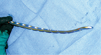
Figure 28.10.
A 4.5-mm tibial LCDC plate with combination holes is contoured for the distal-tibial medial surface with a distal bend and a proximal medial twist. |
and reduction is adjusted for angulation and rotation with small
position changes in the extremity or with reduction clamps placed
extraperiosteally (Fig. 28.11). This is the indirect reduction portion of the case (5).
tension device is placed in the compression mode and compressed to
approximately 60 kPa (step 6, Fig. 28.2D) (7).
This construct, with only one screw and the articulating tension
device, is usually quite stable. This is a good time to obtain
intraoperative radiographs for assessing fracture reduction and
alignment. Standard overhead films or c-Arm images are obtained to
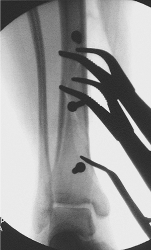
assess the overall axial alignment and preliminary fixation (Fig. 28.12). At this point in the procedure, any step is easily reversed.
fragments should be secured with lag screws placed through or outside
the plate. Additional screws are inserted into the plate to enhance
stability (Fig. 28.13) (step 7, Fig. 28.2D).
The exact number of screws is cannot be precisely predicted, but the
surgeon should balance the fixation by dispersing the screws
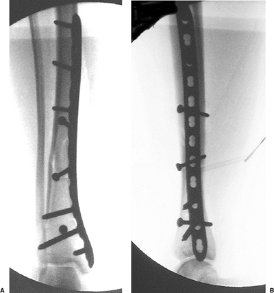
equally on either side of the plate. Intraoperative radiographs are obtained and final fixation adjustments are carried out (Fig. 28.14). The final radiograph should correspond closely with the preoperative drawing.
 |
|
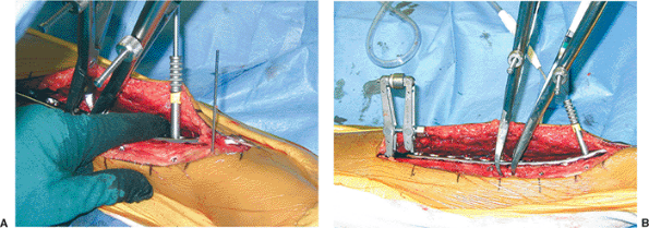
Figure 28.11. A.
The contoured plate is slipped beneath the distal neurovascular structures and applied to the distal fragment with a single locked screw to create a fixed-angle plate. B. The ATD is then placed off a proximal push-pull screw and can be used to achieve distraction if necessary and to fine-tune the reduction. Clamps are used extraperiosteally to secure and fine-tune the reduction as well as to protect the lag screws during distraction and compression. Note the distal drill sleeve for insertion of a second, more distal, locking screw. The ATD creates a load-sharing construct between the implant and bone. |
closed over a small drain. The skin itself is approximated with
interrupted, horizontal, mattress sutures of 4-0 nylon. No tension
should be present at the skin edges at the time of closure (Fig. 28.15).
If tension-free closure cannot be obtained after osteosynthesis, then I
prefer to make multiple, small, relaxing incisions with a no.10 blade
on both sides of the surgical incision; this pie-crusting technique
frequently allows closure without tension. If wound closure without
tension is not possible, then only the portion of the wound that can be
closed without tension is carried out, and the remainder of the wound
is left open. The patient may then be returned to the operating room in
several days for delayed primary closure or flap coverage if necessary.
wound, followed by application of a bulky Jones-type dressing. A splint
may be incorporated into the Jones dressing if desired, particularly if
more distal injuries are present (Fig. 28.16);
the splint also helps to prevent equinus deformity. Postoperatively,
the limb is elevated on a Bohler-Braun frame for 1 to 3 days.
by an associated fibular fracture, which usually does not require
repair. However, if the tibia fracture is proximal or distal, plate
osteosynthesis may be carried out at the time of tibial stabilization
to enhance fracture stability. If the fracture results in excessive
shortening, fibular osteosynthesis carried out before the tibial
osteosynthesis may be additionally helpful. Care must be taken in
preoperative planning to allow for satisfactory skin bridges between
the tibial and fibular incisions, which should be kept to a minimum of
8 cm.
on the first postoperative day with partial weight bearing (20 kg) on
the affected side. The use of locking screws does not affect the
weight-bearing capability of the construct, and full weight bearing on
the plate should not be permitted merely because the screws are locked.
 |
|
Figure 28.12. AP (A) and lateral (B)
intraoperative images after removal of the ATD. The proximal screws are standard, 4.5-mm, cortical screws and the distal screws are 5.0-mm locked screws. Due to fracture configuration, additional lag screws through or outside the plate were not necessary. |
 |
|
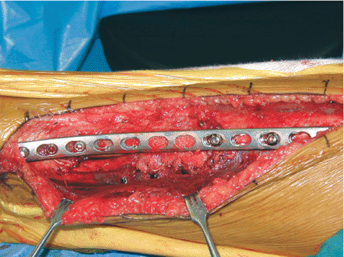
Figure 28.13. Final clinical appearance of extraperiosteal locked plate. Distally (left) the plate is beneath the saphenous structures.
|
 |
|
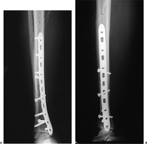
Figure 28.14. AP (A) and lateral (B) radiographs of the final osteosynthesis are made at the conclusion of the case.
|
 |
|
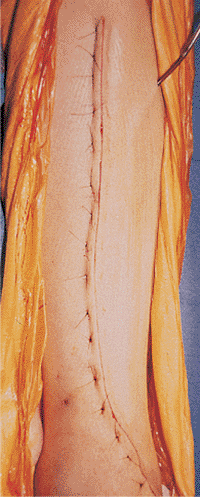
Figure 28.15.
Skin closure is carried out with interrupted, horizontal, mattress sutures of 4-0 nylon. No tension should be present in the skin at the time of closure. |
surgery, followed by removal of the surgical dressing the next day.
Active and active-assisted range of motion of the ankle, hip, and knee
is then initiated. A light dry dressing may be required for several
days for any subsequent wound drainage. Depending on the clinical
situation, any portion of the postoperative regimen may be carried out
on an outpatient basis.
clinical examination and radiographs. Weight bearing is advanced based
on the clinical examination of discomfort or localized tenderness and
the radiographic appearance of the fracture at follow-up. Typically,
weight bearing will be advanced to partial (50 kg) by 6 to 8 weeks and
to full by 8 to 12 weeks.
 |
|
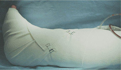
Figure 28.16. Bulky soft-tissue dressing is applied at the conclusion of the operation.
|
that the incision heals uneventfully. Even with the utmost care,
minimal skin and wound-edge necrosis of 1 to 2 mm may be found on
occasion; it usually requires nothing more than observation. More
extended skin and wound-edge necrosis may require surgical excision
with irrigation, debridement, and reclosure of the wound (occasionally
with flap advancement). Significant loss of skin and soft tissue in the
postoperative period may require flap coverage.
after ORIF, should be treated with wound irrigation and reclosure over
drains with or without antibiotic beads if the fixation remains intact
and secure. Late infection in the presence of loosened hardware will
require irrigation, debridement, removal of the hardware, and external
fixation of the tibia until satisfactory wound and soft-tissue
conditions can be obtained.
shaft fracture after ORIF depends on whether the hardware remains
intact or has failed, either by loosening or breakage. If the fixation
remains intact and the soft-tissue conditions are satisfactory, then
delayed union or nonunion may be treated with bone grafting and
maintenance of protected weight bearing. If the internal fixation shows
signs of failure, then the hardware must be removed and the internal
fixation repeated with the addition of bone graft and an additional
period of protected weight-bearing ambulation. Locking plates are not
more difficult to revise than standard plates, and old locking holes
can be reused for new locking screws.
HJ, Tscherne H. Pathophysiology and classification of soft tissue
injuries associated with fractures. In: Tscherne H, Gotzen L, eds. Fractures with soft tissue injuries. Berlin: Springer-Verlag; 1984.
J Jr, Prickett W, Song E, et al. Extraosseous blood supply of the tibia
and the effects of different plating techniques: a human cadaveric
study. J Orthop Trauma 2002;16(10): 691–695.