
maintenance of stability and performance of kinematic tasks renders the
human body one of the most complex machines known. Within its
structure, the multijoint nature of the human spine possesses its own
unique set of biomechanical challenges. A thorough understanding of the
physical forces that govern the static and the dynamic properties of
this anatomic structure is crucial. In this chapter, a basic and
elemental definition of mechanical concepts and terms is presented as
an initial step to understanding spinal biomechanics.
load has evolved from being an aspect of pure materials science to its
own specific discipline of biophysics called rheology. Commonly used “engineering terms,” such as elasticity, plasticity, viscosity, and strength,
although usually used to describe the properties of pure plastics or
metals, can be applied to the characteristics of the materials that
compose the human spine. These properties determine the relationships
between the individual components of the spine, including ligament,
bone, and disc. These terms can be used to describe and forecast the
interaction of implanted devices within the spine. Combined with
information concerning the biologic processes and the details of tissue
physiology, an understanding of the influence of the local mechanical
environment on fusion healing, disc degeneration, and scoliosis
progression can be achieved.
structure. Similar to a skyscraper, the behavior of the construction as
a whole is determined by the interaction of its individual parts and
materials. Steel, glass, and concrete each have their own mechanical
properties (e.g., elasticity, plasticity, ductility). When used in
combination, however, the properties of the new construction are
determined by the relative interplay between the different materials.
The spinal column is a composite structure of bone, ligament, and
intervertebral disc. Although the material properties of these
individual tissues can be defined easily, prediction of the interaction
between the tissues is much more complex and has been the focus of
countless biomechanical investigations.
through surgical intervention. The orthopaedic spine surgeon is obliged
to possess an understanding of basic biomechanics.
-
Force
-
Stress
-
Strain
is defined as the force required to accelerate a 1-kg mass at 1 meter
per second squared. Mathematically, this is written 1 N = 1 kg × 1 m/s2.
or pascals (Pa). Because of the great magnitudes, the typical unit
expressed for most materials concerning the spine is the megapascal
(MPa), which is equivalent to 106 Pa.
of a material under a particular force (or load). It is the ratio of
the new length over the original length and is expressed as ε = (Lfinal – Linitial) / Linitial = ΔL/Linitial. Because the denominator and the numerator have units of length, strain is a dimensionless parameter and has no units.
-
Elasticity
-
Plasticity
-
Viscoelasticity
are independent of geometry and are independent of each other; they include elasticity, plasticity, and viscoelasticity.
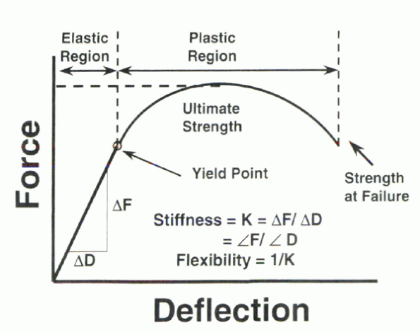
is by examining a spring. When a spring (or other elastic material,
such as bone, which has some springlike properties) is loaded, a
specific amount of deformation is achieved. The deformation is
proportional to the load applied. When the load is removed, the spring
returns to the original geometry. This ideally elastic spring is said
to recover fully from deformation. Up to a specific load, any elastic
material would deform under an applied force (F) and return to its
original geometry on removal of that force. For an elastic material,
the plot of applied forces and resulting deformation would be linear.
The value of the slope within this linear region defines the stiffness
of the elastic material. The stiffness is designated by K and by
definition possesses units of force/deformation (N/m). This quantity
often is expressed in units of N/mm to express the quantity more easily
because biologic samples such as bone typically do not deform to any
great extent (Fig. 31-1).
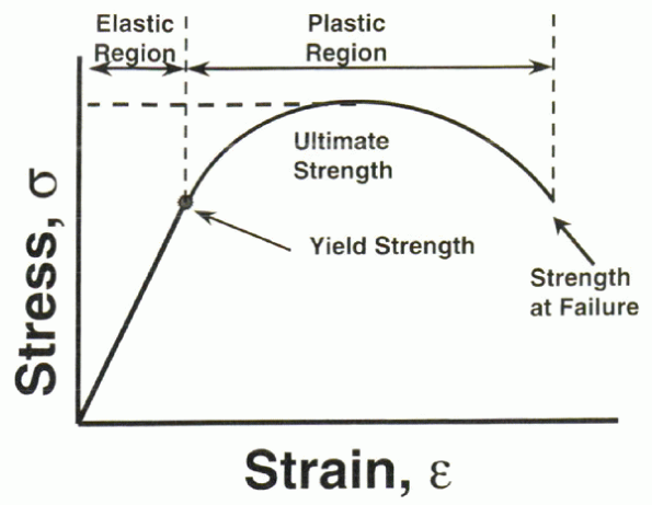
results in a permanent change in the geometry of the specimen on
removal of the deforming force. Plastic deformation is, by definition,
permanent deformation without return to original dimensions. The
plastic region of a material still may possess a linear region;
however, it “recoils” to a point beyond the elastic region. The plastic
region may be long, as the case is for steel or titanium, or it may be
short, as is the case for brittle materials, such as ceramic. The yield point represents the transition from the elastic to the plastic regions (Fig. 31-2). This is the “point of no return” for the material. Any additional deformation beyond the yield point is permanent.
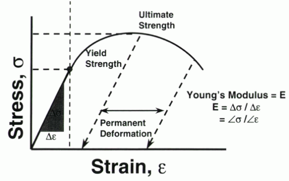
stress versus strain (or the load versus deformation) curve of a
material. In the elastic region of the curve, removal of the applied
load results in nonpermanent change in the geometric dimensions of the
material. When the identical process is repeated in the plastic portion
of the curve, however, a permanent change in deformation results. If a
line is drawn from the point of load release, parallel to the slope of
the elastic curve, it intersects the x-axis of strain (or deformation).
This value is the permanent deformation for the applied load (Fig. 31-3).
 |
|
Figure 31-1
Characteristics of the load versus deformation curve under static loading conditions. (The terms “deflection” and “deformation” may be used interchangeably.) |
 |
|
Figure 31-2 Stress versus strain curve illustrating the elastic and plastic regions of a material under static loading conditions.
|
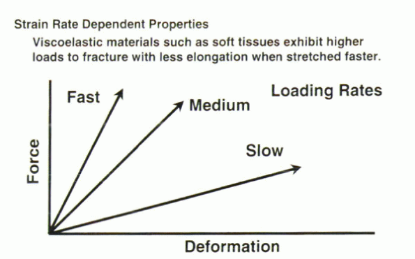
Although the manifestation of this characteristic may be dramatic, as
in soft tissues (e.g., muscle, tendons, and ligaments), viscoelasticity
in harder materials (e.g., bone and cartilage) is more subtle.
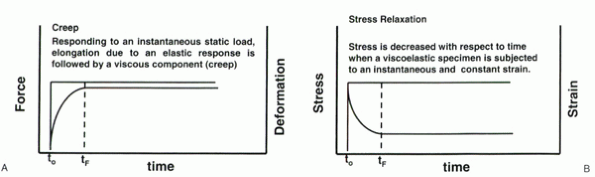
viscosity. Shear and flow are resisted by viscosity. Viscosity is time
dependent in nature (Fig. 31-4). In the case of
an instantaneous load application, a viscoelastic material displays an
initial exponential rise in deformation until a steady state of
deformation is obtained. This equilibrium is achieved when the internal
viscous and material forces are sufficient to resist the collapse of
the applied load. The viscous component of the force resistance is
termed creep and is common to all
viscoelastic materials. The comparable effect is observed when
instantaneous deformation is applied and maintained. In this case, the
viscoelastic properties balance and minimize the internal forces. The
initial stresses decay exponentially to an equilibrium level on
application of an instantaneous and constant strain. This phenomenon is
termed stress relaxation and, similar to
creep, is common to all viscoelastic materials. The resulting
deformation displayed by the material is related to the force magnitude
and the rate of force application (Fig. 31-5).
The deformation rate of a viscoelastic material is directly
proportional to the force magnitude applied. In contrast to
nonviscoelastic materials, no elastic return to the original geometry
results when the applied load is removed.
 |
|
Figure 31-3
Characteristics of the stress versus strain curve under static loading conditions. Note the similarities to the load versus deformation curve in Figure 31-1. Permanent deformation results at load levels beyond the yield point. |
-
Strength
-
Ductility
-
Fatigue
material properties would be useful. The substance of which an object
is composed determines material properties, such as elasticity and
plasticity. These properties are independent of the geometry. The
structural properties of an object are determined by its shape or
geometry. The steel used to create a piece of sheet metal has the same
material properties as the steel used to create an I-beam. The I-beam,
for its intended use to span long segments and act as a weight-bearing
structure, is much stronger, however. Strength (and ductility and
fatigability) is determined partially by the material in addition to
the geometry or dimensions into which it is formed. A biologic
structure, such as bone, also has material and structural properties.
Bone has a specific elastic modulus, stiffness, and other material
properties. The geometry that the bone assumes, such as a hollow tube
(long bone), influences the strength of the bone. A purely structural
property is bending or torsional resistance. It is determined only by
the geometry of an object.
 |
|
Figure 31-4 (A) Visual representation of creep resulting from an instantaneous application of a constant load. (B)
Visual representation of stress relaxation resulting from an instantaneous application of a constant strain. The stress values follow an exponential decrease until equilibrium is achieved. |
at which a material would fail. It is related to the magnitude of force
(or stress) required to cause a structural (rather than material)
failure in the material. Strength is the force beyond which
“catastrophic failure” occurs. It is beyond the yield point of the
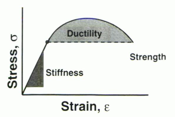
material. The ultimate tensile strength describes the maximal tensile force or stress that a structure can sustain before catastrophic failure.
ductile, strong, and lightweight. These characteristics are not
interdependent and are defined uniquely by the characteristics of the
material. In the load-deflection (or stress-strain) curve, the
stiffness (or modulus in the stress-strain curve) is defined as the
slope of the linear region in the elastic portion of the curve (Fig. 31-6).
It is common practice to perform a linear regression of the load (or
stress) versus deformation (or strain) to compute the stiffness (or
modulus). It also is important to examine the regression coefficient, r2. This value ideally would be equal to unity (or 1) if the result were a perfectly straight line.
number of data points taken during the test. Too few data points decrease the r2
value despite a linear trend. This is an important point to note,
especially in the case of biologic tissues, in which viscoelasticity
and loading rate can influence dramatically the profile of the
load-deformation (or stress-strain) curve. In such cases, too few data
points may lead erroneously to a seemingly linear curve and inaccurate
computation of stiffness or the elastic modulus.
 |
|
Figure 31-5 In viscoelastic materials, the maximal force achieved and the material stiffness are affected by the rate of applied loading.
|
represents the amount of plastic deformation obtained before failure
(i.e., the total deformation between the yield point and the failure point of the material or implant). Consideration of this property is vital in the design of spinal implants. If a device yields but possesses sufficient ductility such that it does not fail
under continued loading (and if this amount of deformation does not
cause pain clinically), the likelihood of clinical implant failure is
low. In contradistinction, if the implant possesses minimal ductility
and it mechanically yields under physiologic loads, failure is likely.
implant design. In the case of operative scoliosis correction, rods
should be stiff to maintain curve correction and to provide sufficient
spinal stability. The rods also must be strong so as to prevent failure
of the implant or construct under cyclic physiologic (fatigue) loading.
Finally, the rods must be ductile so that the surgeon can contour the
rods to the desired shape to achieve curve correction. If the rod was
not ductile, bending it would lead to potential breaking points that
eventually would lead to implant failure.
 |
|
Figure 31-6
Ideal implants display a sufficiently high stiffness property in addition to a large region of ductility to prevent catastrophic failure. |
 |
|
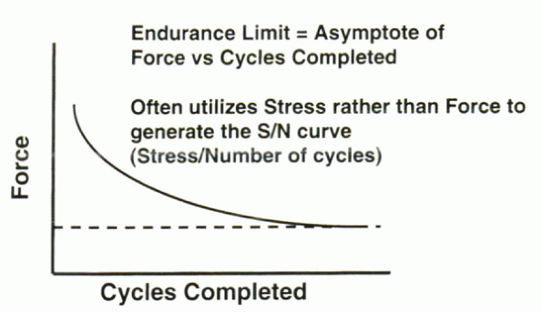
Figure 31-7 Typical load versus cycles to failure curve. At some applied load no failure will occur, regardless of the number of cycles.
|
The number of cycles to failure for a given material may be different
in different loading directions. Bone is strongest under compressive
loads, but it is weakest, and usually fails, under torsion or bending
loads.
This is the load magnitude below which failure would not occur
regardless of the number of cycles applied to the material. This
property is crucial when considering the design and selection of
material for an implant. The endurance limit of the final design should
be well above the anticipated maximal physiologic loads.
related to the cross-sectional area of a structure and is a fundamental
geometric property of the structure. The moment of inertia describes
the spatial distribution of material within a structure with respect to
a particular axis of rotation or bending. The equation is expressed as
I = Σ miri2—the sum of each elemental mass (mi) that is located at a distance (ri)
from the neutral or selected axis. For most geometric structures, with
a central axis of symmetry, such as a round rod or rectangular plate,
moments of inertia can be calculated using simple equations.
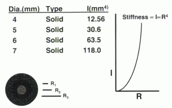
only and is not related to the material used. One of the most useful
applications of this property is calculation of resistance to bending
for various structures. A large increase in the bending resistance of a
rod can be achieved by small increases in the rod’s diameter (Fig. 31-8).
For cylindrical objects with a neutral axis through their center, the
moment of inertia is proportional to the fourth power of the rod radius
(r). The equation defining this relationship is:
the moment of inertia for a 7-mm rod is 10 times that of a 4-mm rod.
 |
|
Figure 31-8
The moment of inertia for a cylindrical rod is proportional to the fourth power of the radius. Small increases in radii can manifest large increases in the moment of inertia and the resulting stiffness of the rod and construct. |
to the height cubed. To a lesser degree, increases in the height of the
object (or thickness) result in exponential increases in the bending
resistance. Using an equation, this can be expressed as:
inertia creates a stiffer rod. The overall effects of spinal implants
must be considered in concert with the mechanical properties of the
spinal column itself, however. Although the spine is a composite
structure by itself, it becomes more so with the introduction of
instrumentation. Using the example of the rod, the resulting stiffness
is a combination of spinal column stiffness and the rod. This stiffness
is highly influenced by the location of the implant within the spine
and the dimensions and materials properties.
definition unknown. Although various underlying genetic, neurologic,
muscular, and skeletal mechanisms have been suggested, none seem to be
solely responsible for development of this disorder. More recently, a
biomechanical explanation of the initiation of scoliosis has been
suggested. This explanation is grounded in considering the spine as a
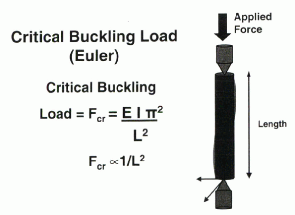
buckling column.
thin (compared with the dimensions of the entire body) column. Under
compressive loading, such a structure would fail primarily through
“buckling.” Euler computed that the critical buckling load is defined
by:
It is the load at which buckling is initiated, and it is inversely
proportional to column length. It follows that the longer the column,
the less force required to achieve buckling.
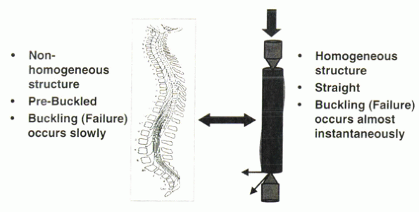
of homogeneous material. The human spinal column is not such a
structure. It is composed of discs and bone among a complex of muscles
and ligaments. The natural curvature of the spine (cervical lordosis,
thoracic kyphosis, and lumbar lordosis) resides in an already buckled,
or “prebuckled,” condition. Although Euler considered buckling to be
catastrophic for a structure, this is not the case for the human spinal
column.
occurs over time. It does not lead to catastrophic failure immediately.
Scoliotic buckling results in disharmony of the normal spinal
curvature, producing abnormal coronal buckling. The critical buckling
force to produce a scoliotic curve may be used to predict what loads
(from the head, trunk, and extremities) might lead to a progressive
scoliotic curve (Fig. 31-10). The critique of
such theoretical calculations is that they do not take into account the
osteologic and ligamentous responses to these forces, which would be
crucial in the growing adolescent spine.
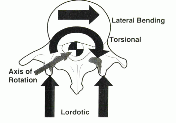
When the lumbar spine undergoes rotation, lateral bending also occurs.
This relationship is commutative, in that lateral bending of the spine
induces rotation. In reverse, derotation of the spine should correct
coronal deformity. This correction is maximized by resection of other
structures, such as the costovertebral joints in
the
thoracic spine that propagate rotation. The resultant coupled motion
decreases the scoliotic curvature. Conversely, the rotation of the
spine leads to rib cage deformity.
 |
|
Figure 31-9
Euler’s formula for the force transmitted through a long cylindrical column supported and loaded by a single point. The critical buckling load for a column is inversely proportional to the square of the column length. |
 |
|
Figure 31-10 The human spine is a prebuckled nonhomogeneous structure in which pathologic buckling occurs gradually.
|
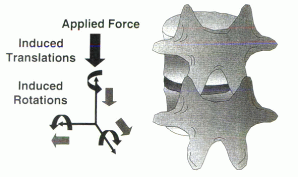
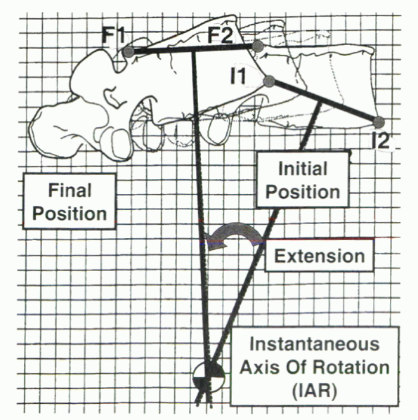
about which all other parts rotate. In the spine, the axis is not
located at a single point, but because of the intricacy of the
three-joint structure, it moves within a complex pattern (or
collection) of points. To preserve the relative position of the neural
elements, the axis of rotation in the transverse plane is located
within the spinal canal (Fig. 31-12). Although
considerable work has been done in attempting to locate the locus of
the axis of rotation during flexion/extension and lateral bending, the
definitive answer remains elusive because in vitro investigation can
only simulate in vivo motion, with one vertebra moving in relation to
an adjacent fixed vertebra. Physiologically, both vertebrae are moving
relative to a global reference frame and relative to each other (Fig. 31-13).
The local reference frame is in motion. With that said, it generally is
believed that the sagittal axis of rotation is located within the
center of the intervertebral disc (Fig. 31-14).
 |
|
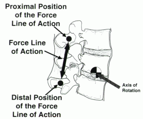
Figure 31-11 Force direction generated by proper instrumentation and implantation can be used to control spinal deformity in various planes.
|
 |
|
Figure 31-12 Instantaneous axis of rotation during motion of a single vertebral body in relation to a fixed location.
|
 |
|
Figure 31-13
The instantaneous axis of rotation (IAR) in vivo is influenced by the relationship of one vertebra with another and the orientation of both vertebrae in relation to a global reference frame. |
 |
|
Figure 31-14 During flexion/extension movements, the estimated axis of rotation is located within the center of the intervertebral disc.
|
generation of geometrically scalable anatomic models complete with soft
tissues. Although this undertaking may yield new insight, the focus
should remain on the influence of physiologic loading. From a practical
perspective, such complex loading conditions would be enormously
difficult to simulate in an in vitro setting. Even if computationally
possible, experimental verification would be nearly impossible, with
the task remaining an academic exercise.
L, Lange U, Knop C, et al. Evaluation of the mobility of adjacent
segments after posterior thoracolumbar fixation: a biomechanical study.
Eur Spine J 2001;10:295-300.
PJ Jr, Polly DW Jr, Cunningham BW, Klemme WR. The effects of hook
pattern and kyphotic angulation on mechanical strength and apical rod
strain in a long-segment posterior construct using a synthetic model.
Spine 2001;26:627-635.
PA, Jain GM, Wittenberg RH, Nolte LP. Load-sharing characteristics of
stabilized lumbar spine segments. Spine 2000; 25170-25179.
TR, O’Brien M, Felmly WT, et al. Instantaneous axis of rotation as a
function of the three columns of the spine. Spine 1992;17: S149-S154.