
unstable fractures of the posterior pelvic ring including sacroiliac
(SI) joint dislocations; sacral fractures; certain, posterior, iliac
“crescent” fracture-SI disruptions; and combinations of these injuries.
This technique can be used alone or in conjunction with other forms of
pelvic internal or external fixation. The timing of internal fixation
for displaced pelvic-ring injuries depends on numerous factors such as
the fracture pattern, local skin condition, hemodynamic status, patient
age and body habitus, and abdominal or urologic injuries.
iliosacral screws safely. The surgeon must completely understand normal
posterior-pelvic anatomy, as well as its variations, especially the
upper-sacral structure. High-quality fluoroscopic imaging of the entire
pelvis must be available during surgery. The surgeon must completely
understand the specific injury and the displacement patterns of the
posterior pelvic ring and be able to correlate normal and altered
pelvic pathologic conditions as seen on radiographic images. Based on
the preoperative plain radiographs and computed tomography (CT) of the
pelvis, the surgeon must be confident that the patient’s upper-sacral
anatomy will allow safe screw placement. Finally, the surgeon must
possess the technical skill to reduce the posterior pelvic deformity
accurately by closed or open techniques. Iliosacral screws should not
be used unless the injured area is reduced.
contraindication for insertion of iliosacral screws. The dysmorphic
upper sacrum is a common anatomical variant that decreases the
upper-sacral, alar, osseous area available for safe screw passage into
the sacral body. Because of the complex anatomy of the pelvis,
dysmorphic sacral segments can be difficult to identify predictably
during surgery. Upper-sacral-segment abnormalities occur in 30% to 40%
of patients and are best identified on the outlet radiograph and CT
scans of the pelvis. These abnormalities are most often symmetrical but
are unilateral
in
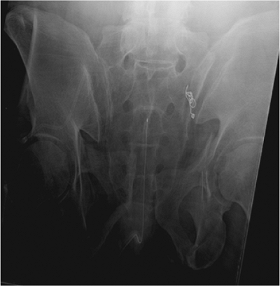
some patients. The radiographic outlet-image hallmarks of
upper-sacral-segment dysmorphism include the following: (a) the
lumbosacral disc space is colinear with the iliac crests, (b) the
ventral foramen of the upper-sacral nerve root is not circular in
appearance, (c) residual disc space is noted between the upper and
second sacral segments; (d) the dysmorphic ala decline acutely from the
upper-sacral body to the SI joints; and (e) mammillary processes are
present on the dysmorphic ala. On the CT scan of the pelvis, sacral
dysmorphism is noted by accentuated, undulating, SI surfaces; an
obliquely oriented, anterior, alar cortex relative to the iliac
cortical density (ICD); and a narrowed alar zone available for screw
insertion (Fig. 39.1).
screw fixation for several reasons. Intraoperative fluoroscopic imaging
in obese patients is compromised by the excessive abdominal panniculus,
which may obstruct inlet and outlet images of the pelvis. Lateral
pelvic-flank obesity limits true lateral sacral imaging. Fluoroscopic
detail in obese patients may be inadequate for safe guide-screw
placement. In addition, extra long instruments such as drills, taps,
and screwdrivers are necessary for treating the obese patient.
in some polytraumatized patients because of contrast agents that were
used during the initial abdominal evaluations. Therefore, it should be
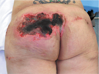
avoided when possible. In patients with open fractures or compromised
posterior skin and soft tissues, iliosacral screw placement should be
done percutaneously when possible, rather than through an open
approach. In a common mistake, the surgeon enters and inadvertently
decompresses a pelvic degloving injury during the process of iliosacral
screw insertion. In such situations, the screw is inserted, the
degloving area irrigated and debrided, and the dead space closed over
suction drains. In severe cases, the dead space is packed open (Fig. 39.2).
 |
|
Figure 39.1.
Upper-sacral dysplasia is common. It is best identified on the outlet pelvic radiograph as shown here. The hallmarks include (a) lumbosacral disc space that is nearly colinear with the iliac crests, (b) mammillary processes on the sacral ala, (c) sacral ala that are acutely and laterally sloped, (d) nonspherical ventral neuroforamen of the first-sacral nerve roots, and (e) residual disc exists between the two upper-sacral segments. Upper-sacral dysplastic segments have narrowed safe zones for iliosacral screw insertion and must be recognized. Further imaging with CT scanning of the pelvis is used to assess the safety of iliosacral screw insertion. |
 |
|
Figure 39.2.
Closed or open, traumatic, degloving wounds occur when the skin and fat are separated from the underlying muscle fascia. Most often found after a crushing blow, these injuries are seen at the flank and lumbosacral areas in association with unstable pelvic-ring disruptions. This patient was crushed by an automobile and sustained pelvic ring and soft-tissue degloving injuries. On the day after her accident, she was treated with closed manipulated reduction and percutaneous iliosacral-screw fixation of her pelvic fractures. Her lumbosacral skin became necrotic 3 days after injury. The skin and local tissue necrosis evolved and was then surgically debrided 5 days after injury. Open wound management was selected for almost 2 weeks, and the area was then covered with a skin graft. The iliosacral screw fixation provided pelvic stability and allowed prone-patient positioning for easier wound management in the absence of an anterior-pelvic external fixator. |
pelvic-ring injury, resuscitation using advanced trauma life support
(ATLS) protocols has been shown to reduce morbidity and mortality
rates. Large-bore intravenous access allows rapid volume infusion, and
the patient is kept warm. The potentially injured pelvis can be
immobilized at the accident scene before patient transport through use
of a variety of simple techniques. A vacuum beanbag, a large
circumferential sheet, and military antishock trousers (MAST) are
recommended for temporary stabilization of the pelvis. Pelvic wrapping
devices are also commercially available but are costly, and they often
add to an overloaded inventory. Sheets are readily available,
inexpensive, and can be adjusted in width to fit any body habitus. They
can be reused or discarded, require no additional inventory, and can be
positioned or trimmed to allow groin, perineal, flank, abdominal, or
combination access for other resuscitation or evaluation procedures.
Regardless of the technique chosen, pelvic overcompression should be
avoided.
visual evaluation performed by the most experienced physician and then
communicated to the rest of the treatment team. A detailed neurologic
examination is documented in alert patients. During the examination of
the pelvic area, the surgeon identifies abrasions, contusions,
degloving injuries, or open wounds. Sterile pressure dressings are
applied to open pelvic wounds to diminish ongoing bleeding. The
lumbosacral palpation and visual, along with the digital rectal,
examinations are performed during the posterior spine assessment after
the patient has been log rolled by a team of assistants. The mechanical
evaluation of the pelvis is ideally performed under fluoroscopic
imaging. Pelvic ring instability is noted as gentle manual pressure is
applied simultaneously toward the midline on each iliac crest. This
maneuver produces significant pain in alert patients with pelvic ring
instability, iliac fractures, and certain acetabular fractures. Local
pain during iliac manual compression can also be due to iliac area
contusions in the absence of pelvic-ring osseous injury. To prevent
fracture-surface clot disruptions (among other potential consequences),
vigorous and repetitive, manual, pelvic examinations are not
recommended. Digital rectal, prostatic, and vaginal examinations are
performed to test for both
gross
and occult blood. The vaginal and rectal exams are initially done with
the patient supine or log rolled into the lateral position. A more
thorough speculum vaginal exam is deferred until pelvic stability is
achieved so the patient can be placed safely in the lithotomy position.
anteroposterior (AP), plain radiograph of the pelvis. A complete
radiographic series includes orthogonal views (inlet/outlet), and a
lateral sacral image should be obtained especially in patients whose
screening AP films show a “paradoxical inlet” of the upper-sacral area.
A CT scan of the pelvis is essential to further delineate the fracture
anatomy. The CT scan images of the pelvis indicate the patient’s body
habitus, reveal related soft-tissue abnormalities, such as hematoma, as
well as degloving injuries and their extent, and also show contrast
extrusions reflecting bladder, vascular, or other injuries. The pelvic
CT images also show the lumbosacral nerve-root positions as well as
sacral alar fractures. The iliac vessels and their relationship with
displaced, superior-pubic ramus fractures are often seen clearly on the
images. With similar clarity, displaced inferior-ramus fractures can be
identified as they intrude on the vagina or are displaced anteriorly.
The CT scan details subtle osseous injuries missed on the plain films
and shows the hemipelvic displacement patterns. An ipsilateral
pneumothorax can often be seen on CT scans of the pelvis because the
subcutaneous air extends to the iliac area.
dependent on the clinical condition of the patient, institutional
capabilities, and surgeon availability and expertise. Hemodynamically
unstable patients with unstable pelvic-ring injuries require some form
of rapid pelvic stabilization. Anterior-pelvic external-fixation frames
and posterior-pelvic antishock clamps have been advocated to stabilize
the pelvic ring rapidly. When possible, the pelvic external-fixation
system is applied through use of iliac crest pins inserted after a
closed reduction is obtained and maintained by the circumferential
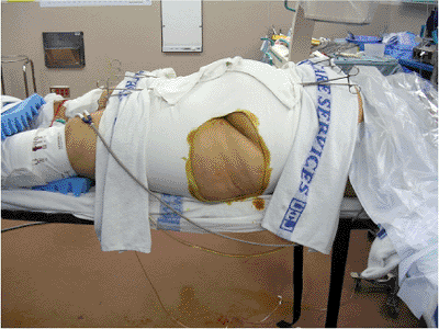
pelvic wrap. Access holes are cut in the sheet overlying the iliac
crest. The skin is prepped and the pins inserted between the iliac
cortical tables. We recommend application of such devices using the
fluoroscopy unit in the angiographic suite when possible. The
circumferential wrap can also be adjusted through use of the same
imaging unit to assess and adjust the pelvic closed-manipulation
reduction. If the reduction has been achieved, iliosacral screws can
also be inserted using access portals in the sheet (Fig. 39.3).
In selected hemodynamically unstable patients, pelvic angiographic
embolization is helpful in controlling pelvic arterial bleeding.
 |
|
Figure 39.3.
This morbidly obese adult female pedestrian was struck by a vehicle. She suffered a right-sided, pertrochanteric, closed-femur fracture and bilateral, unstable, pelvic-ring disruptions. A circumferential pelvic sheet provided an excellent closed reduction of the pelvic injuries. With the circumferential sheet in place, the physician made a surgical portal by cutting a portion of the sheet away without compromising its function. The area was prepped and draped, and iliosacral screws were inserted to stabilize definitively the left hemipelvis. The right-sided posterior-pelvic injury was stabilized next through the same technique. The sheet was removed and the reductions were maintained. Her abdominal obesity prevented anterior-pelvic external fixation. |
(ORIF) induces the risk of bleeding and has a higher complication rate,
but for certain patients and injury patterns, the benefits may outweigh
the risks. Percutaneous, posterior-pelvic, internal fixation through
use of iliosacral screws minimizes the bleeding risk, is quick, and is
useful when an accurate closed-manipulated reduction of the posterior
pelvic-ring injury can be accomplished. Percutaneous iliosacral screws
may be used in emergency resuscitation situations in combination with
standard anterior-pelvic external fixation. In patients who are
hemodynamically stable, operative pelvic stabilization should be done
early. Before surgery, distal femoral traction improves the reduction
and provides patient comfort.
should consider the mechanism of injury, associated major-system
injuries, and the local soft-tissue conditions. Special attention is
given to an analysis of the plain films and CT scans. On occasion,
iliac and obturator oblique radiographs of the pelvis are obtained in
patients with concomitant acetabular fractures. A two-dimensional CT
scan further delineates the specific sites of injury and direction of
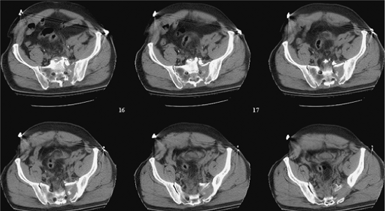
displacement (Fig. 39.4). Just as important as
detailing the injury and local anatomy, the two-dimensional CT scan
also is used preoperatively to determine the number of screws that can
be inserted, the upper-sacral anatomy, the planned starting point on
the lateral ilium, and the screw direction and length needed to achieve
stable and balanced fixation (Fig. 39.5). Some
clinicians prefer three-dimensional CT scans to improve their
understanding of the fracture details and deformity patterns (Fig. 39.6).
examination, and the radiographic studies, the surgeon formulates a
plan. The preoperative plan includes all of the surgical details
including timing, patient positioning, exposures, reduction strategies,
clamp application sites, fixation techniques, and treatment
alternatives. Even the anticipated rehabilitation goals are planned
preoperatively; they are especially important for polytraumatized
patients.
iliosacral screw fixation, and the surgeon should be familiar with
various anterior-pelvic and posterior-pelvic operative
exposures
and fixation techniques as well as percutaneous reduction and fixation
strategies. The treatment plan must be tailored to the individual
patient. Insertion of iliosacral screws can be performed with the
patient in the supine, lateral, or prone position; each patient
position has advantages and disadvantages. The lateral position
complicates both anterior-pelvic and posterior-pelvic surgical
exposures and is not recommended for patients with potential spinal
injuries. Prone positioning allows posterior surgical exposures but
denies the surgeon simultaneous anterior-pelvic surgical access.
Anterior-pelvic external-fixation frames further complicate prone and
lateral patient positioning for surgery.
 |
|
Figure 39.4.
These sequential CT axial images of the pelvis reveal much information. They demonstrate patient body habitus, fracture location, fracture comminution, displacement patterns, nerve root involvement, occult injuries not previously noted on plain films, local bone quality (including that of the upper-sacral dysplasia), soft-tissue degloving injuries, hematoma, contrast extravasation, soft-tissue and/or intra-abdominal air, among other important clinical details that may impact urgent and definitive care. The anticipated reduction maneuvers, clamp application sites, and the upper-sacral safe zone for iliosacral screw(s) can be assessed on such CT images of the pelvis. |
 |
|
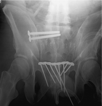
Figure 39.5.
Percutaneous iliosacral screws were used to stabilize this patient’s SI fracture-dislocation. The symphysis pubis was treated with open reduction and plate fixation. The local soft-tissue injury was extensive. The symphyseal reduction in combination with right-sided distal-femoral traction indirectly reduced the SI injury well. Two fully threaded, balanced iliosacral screws were inserted to stabilize the posterior pelvic injury. This postoperative plain film of the pelvis reveals the associated caudal anterior-sacral impaction fracture. This patient also had a urethral tear, which was treated with realignment of symphyseal reduction and fixation. |
 |
|
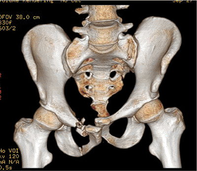
Figure 39.6.
Three-dimensional CT scanning reveals the pelvic injury zones but not in sufficient detail to be used alone in planning. Just as when viewing two-dimensional CT images, the surgeon must know if the patient is wrapped in a pelvic circumferential sheet or other type of pelvic binder at the time of the CT scanning. |
detail during patient positioning, as well as skin preparation and
draping, is mandatory. In polytraumatized patients, the supine position
is familiar, allows several teams to work simultaneously on injured
extremities, and also provides anterior pelvic access. With this
approach, patient position adjustments and repeated drapings are
avoided; thus valuable time is saved.
like neurodiagnostic monitoring, are intended to simplify the procedure
by making it safer. Computer navigation systems are not a substitute
for the surgeon’s thorough knowledge of the sacral anatomy and
radiology. Current navigation systems do not accommodate fracture
displacements that can occur between the time of the preoperative CT
scan and the intraoperative navigation. Early results have shown that
navigation systems for iliosacral screw insertion may decrease the use
of fluoroscopy but not overall surgical time.
cephalosporin are administered before the patient is moved onto the
operating room table. Spinal precautions protect the patient during
transfer from the bed and positioning on a fluoroscopically compatible
operating table. Several strong assistants are needed to elevate the
patient from the operating table so the surgeon can position a soft,
lumbosacral, spinal support. This support consists typically of two (or
more) stacked and folded operating-room blankets. Too much elevation
and the patient is in an unstable position and will lean to one side or
the other. Elevating the patient’s pelvis from the operating room table
is necessary to allow posterior-pelvic percutaneous access. If needed,
distal-femoral pin traction is continued through use of a pulley system
attached to the operating table (Fig. 39.7).
patients with transforaminal sacral fractures undergoing closed
manipulated reductions and percutaneous iliosacral-screw fixations.
Neurodiagnostic monitoring is not used as a substitute for surgeon
competence, a detailed preoperative plan, or adequate, intraoperative,
fluoroscopic imaging. The surgeon must understand the posterior pelvic
anatomy and its fluoroscopic correlations. The surgeon must not use
monitoring to direct screw insertions in a random manner while hoping
to find a safe area for the screw. Neurodiagnostic information also may
be confusing, especially with regard to patients with preoperative
neurologic abnormalities, when information is falsely positive, and
when clinical correlation is lacking. Neurodiagnostic monitoring is not
a safety net that will protect the surgeon from lack of knowledge
regarding sacral anatomy.
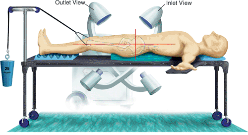
on the side opposite from the injured posterior hemipelvis. The initial
AP fluoroscopic image of the pelvis is used simply to assess proper
patient positioning. Minor position corrections are made and confirmed.
This
view can also be used if preoperative mechanical stability is to be
assessed under fluoroscopy. Surprisingly, certain “nondisplaced”
fracture sites thought to be previously insignificant may show
impressive instability under fluoroscopy. These “nondisplaced”
fractures should not be ignored.
 |
|
Figure 39.7.
The patient is positioned supine and elevated on two folded and stacked blankets, which act as a lumbosacral support. This operating table has no central support and allows extremes of fluoroscope rotation and therefore pelvic imaging. Distal femoral traction is made possible through use of a pulley system anchored to the foot of the table. |
until perfect inlet and outlet posterior-pelvic images are obtainable.
The ideal inlet image of the pelvis superimposes the upper-sacral
vertebral bodies as concentric circles, but it is the most difficult
and least reliable view of the three standard images used
intraoperatively. For dysmorphic upper-sacral segments, anterior,
cortical, alar indentations mark the anterior cortical-alar limits and
are noted on the inlet image.
superior aspect of the symphysis pubis is superimposed on the second
sacral-vertebral body. The surgeon should carefully examine this outlet
image, which reveals the corticated pathway of the upper-sacral nerve
root. These bilateral pathways are osseous tunnels that begin
posteriorly, superiorly, and centrally at the spinal canal at the same
level as the lumbosacral disc space. These bilateral tunnels course
anteriorly, caudally, and laterally from their spinal canal origin and
end as the ventral foramen of the first-sacral nerve root. The
radiographic appearance on the outlet image of these bilateral
corticated pathways is like that of a small spica cast. Under the spica
cast model, the body of the spica cast is the spinal canal, while the
thigh components of the spica cast are the sacral nerve-root tunnels
passing from the spinal canal to the ventral sacral foramen. The
corticated edges of the nerve root pathways/tunnels allow their
radiographic visualization in the operating room and on the plain
preoperative radiographs. This spica cast analogy lends a
three-dimensional quality to a two-dimensional outlet image, giving a
preoperative depth perception to the surgeon of the upper-sacral nerve
pathway. This is invaluable radiographic intraoperative information.
tilt is adjusted to focus on the segment that will receive the
iliosacral screw. In some dysmorphic patients, iliosacral screws are
inserted into the narrowed upper-alar site and also into the second
segment, which may be a more expansive area for screw insertions. If an
upper-sacral-segment screw is chosen for a dysmorphic patient, the
surgeon must understand that the anterior borders of the sacrum at S1
and S2 are different and therefore unique fluoroscopic markers
highlight each specific site. The outlet view will predictably reveal
the nerve root tunnels for each segment. The true lateral view will be
disturbing with regard to the dysmorphic upper-segment screw insertion
because the upper-sacral segment is superiorly located relative to the
superimposed ICDs. Therefore, this image looks as though no lateral
sacral-alar mass is safe for screw location. The preoperative plan will
assure the surgeon that the screw orientation will be directed from a
posterior-caudal starting point with an anterior-cephalad directional
aim. Because of the unusual anatomy, these upper-sacral screws can
rarely extend beyond the midline.
of the pelvis are essential to visualize the upper sacrum. Image
enhancement and alternating negative images on the fluoroscope often
improve imaging of the posterior pelvis. The arc of rotation of the
fluoroscope needed to obtain these “perfect” images varies for each
patient and depends upon the degree of lumbosacral lordosis and
deformity due to the injury. The amount of tilt needed to obtain
perfect inlet and outlet views is marked on the fluoroscope arm by the
technician, and the machine’s wheel positions on the floor are also
marked to facilitate subsequent rapid imaging. Minor rotational changes
of the fluoroscope identify the tangential posterior-pelvic disruptions
and may be useful in certain sacral fractures.
adjusting the fluoroscope to superimpose the greater sciatic notches.
On the almost-true lateral sacral image, the iliac cortical densities
are identified and correlated with the preoperative CT scan once again
so the surgeon understands where the anterior sacral ala are located.
The ICDs mark the alar locations according to the preoperative CT scan
information. The safe sacral segment for screw insertion is
reconfirmed. Significant hemipelvis deformity causes this almost-true
lateral sacral view to be of little use. A “true” lateral sacral image
is possible only after accurate posterior-pelvic fracture reduction or
in patients with minimal posterior-pelvic deformities.
orthogonal imaging, especially the inlet view of the pelvis. These
osteophytes are best seen on the true-lateral sacral image. The true
lateral is also used to identify transverse sacral fractures and their
displacements.
extremities are prepared with iodine solution followed by isopropyl
alcohol. The scrotum, penis, and any urinary catheter are included in
the operative field when combined urologic procedures are planned. Wide
preparation of the posterolateral buttock skin is important and
simplifies iliosacral screw insertion. Femoral vascular catheters,
enteral feeding tubes, suprapubic urinary catheters, and other
essential anterior-abdominal lines are prepared as skin. Ostomy sites
are excluded from the surgical field. Chest tubes are positioned and
isolated from the planned operative field. Sterile electrodes for
neurodiagnostic monitoring are applied to the lower extremities if
indicated.
of the posterior pelvic ring is the goal of surgery. Reduction of
pelvic ring fractures can be accomplished through use of a variety of
techniques. Anatomic reduction and stable fixation of the anterior
pelvic injury “indirectly” improve the posterior pelvic displacement,
especially when supplementary manipulation techniques are used.
Reduction forceps are used temporarily to stabilize open reductions,
whereas other techniques are used to maintain closed manipulated
reductions. Early surgical treatment improves the accuracy of closed,
manipulated, posterior-pelvic reductions. An anterior external-fixation
device [or a femoral distractor–pelvic compressor (Synthes, Paoli, PA)
attached to the iliac fixator pins] can be used as a “pelvic compressor
or distractor” to improve the closed reduction (Fig. 39.8).
and cephalad deformities of the posterior pelvic ring. The fluoroscopic
inlet and outlet images of the pelvis confirm the
reduction
before iliosacral screw fixation. In some situations, a perfectly
placed iliosacral lag screw is used to reduce the posterior pelvic
disruption. While iliosacral lag screws can be used to reduce certain
distracted sacral fractures, the procedure puts nerve roots at risk for
injury (Fig. 39.9).
Open reductions are performed when closed manipulation techniques fail
to provide an accurate posterior-pelvic reduction. Even after open
reduction of the posterior pelvis, percutaneous iliosacral screws are
used to provide stability whenever possible (Fig. 39.10).
 |
|
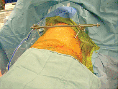
Figure 39.8.
In this clinical photograph, a threaded external bar is applied between the iliac pins and functions as an external pelvic manipulator. It can be used to compress or distract pelvic displacements. Complex, multiplanar, pelvic deformities can be manipulated if the device is applied obliquely between the iliac pins. Iliosacral screws are inserted to maintain the posterior-pelvic manipulated reduction. |
 |
|
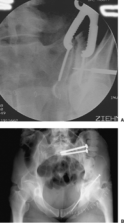
Figure 39.9. A.
An iliosacral lag screw is targeted for reduction of a SI joint dislocation. This patient was hemodynamically unstable after appropriate resuscitation. The screw was used to achieve urgent posterior-pelvic stability. B. As the lag screw is tightened, the reduction is improved but is not anatomical. The SI manipulated screw reduction can be revised at a subsequent surgery through use of open reduction when the patient’s clinical condition is optimized. In such situations, this lag screw functions as an internal posterior-pelvic antishock clamp. |
 |
|
Figure 39.10. A.
Through surgeon’s use of anterior exposure of the SI joint, the reduction clamp is applied between two screws across the joint and then is used to manipulate and hold the open reduction. The guide pin for a cannulated iliosacral screw is percutaneously inserted as shown on this intraoperative fluoroscopic image. B. Iliosacral screws were used to definitively stabilize the SI joint after open reduction. The initial lag screw compressed the joint while the subsequently inserted, fully threaded, iliosacral screw was used to fortify the SI fixation construct. |
Kirschner (K) wire is inserted under fluoroscopic control from the
lateral buttock onto the lateral ilium. This small-diameter smooth wire
resists bending during insertion, which allows accurate aiming yet
causes minimal trauma to the local soft tissues. A predictable starting
point on the skin is located in a posterior cephalad quadrant that is
formed by intersecting lines. One line parallels the femoral shaft,
whereas the perpendicular intersecting line is made from the palpable
anterior–superior iliac spine (ASIS) toward the operating table. The
posterior-superior quadrant marks the sacrum.
of the pelvis are used to direct the orientation of the K wire. Perfect
wire direction and starting point may require several skin punctures
with the smooth wire. The perfect starting point and wire direction are
maintained by gently tapping the wire to engage the lateral, iliac,
cortical bone. The skin is then incised around the wire, and blunt deep
dissection is accomplished with a narrow periosteal elevator or a drill
guide. A long drill guide is placed over the wire, and a 2-mm
terminally threaded guide pin is exchanged for the wire. The drill
guide provides deep control of the guide pin and protects the deep soft
tissues from injury. The guide pin is inserted with a power drill into
the lateral iliac cortex, and its direction is confirmed through
fluoroscopy. Because the guide pin is only slightly engaged in bone at
this point, the surgeon can still use the drill guide to make minor
directional pin corrections. Frequent inlet and outlet images of the
pelvis are used as the pin is inserted from the ilium, across the SI
articulation, and into the lateral aspect of the sacral ala. The guide
pin is halted within the ala when its tip is located just cephalad to
the upper-sacral corticated tunnel edge as seen on the outlet image.
When carefully evaluated, the outlet image will identify the corticated
edges of the osseous tunnel of the upper-sacral nerve root that is
immediately superior and medial relative to the ventral foramen. Once
identified, the nerve root path is better understood. The surgeon must
know that the nerve root passes from posterior to anterior, midline to
peripheral, and superior to inferior (Fig. 39.11).
a true lateral sacral image by fluoroscopically superimposing greater
sciatic notches of each reduced hemipelvis. If the posterior pelvic
reduction is accurate and no sacral dysmorphism had been identified in
the preoperative plan, then the true lateral sacral image identifies
the guide pin tip and its relation with the ICD. The preoperative CT
scan reflects the relation between the ICD and the sacral ala. The
correlation of this information, coupled with the intraoperative ICD,
indicates whether the pin tip is safely placed. The tip of the guide
pin should be caudal to the ICD and cephalad to the intraosseous path
of the upper-sacral nerve root, which is also visible on the
true-lateral sacral image of some patients. The true lateral image
should show that the guide-pin tip is located within the midportion of
the alar bone.
vertebral body to (but not beyond) the midline. The guide-pin depth is
measured with the reverse ruler, and a cannulated drill is advanced
over the guide pin. A cannulated tap is used to prepare the pathway
when necessary. A 7.0-mm cannulated cancellous screw of appropriate
length is inserted over the guide pin and tightened. As for SI joint
disruptions, partially threaded cancellous screws with 32-mm thread
lengths are chosen when compression fixation is necessary. Fully
threaded 7.0-mm cancellous screws are used when compression fixation is
not desired, such as after accurate reductions of transforaminal sacral
fractures. Fully threaded screws also are used when needed to
supplement previously applied compression-screw fixations.
insertion, the surgeon obtains frequent fluoroscopic images to assure
no binding and inadvertent advancement of the guide pin. A 20- to
30-degree obturator oblique (“rollover”) image is used to visualize the
tangential posterior ilium as the screw is tightened. With this image,
the washer is noted to flatten as it contacts the ilium. Using a washer
and this rollover image, the surgeon prevents inadvertent screw
penetration into the posterior ilium. He/she must be careful not to
overtighten the screw and penetrate the lateral iliac cortex. This
complication can occur in older patients with thin iliac-cortical bone
and in young patients when the screw is forcefully tightened.
 |
|
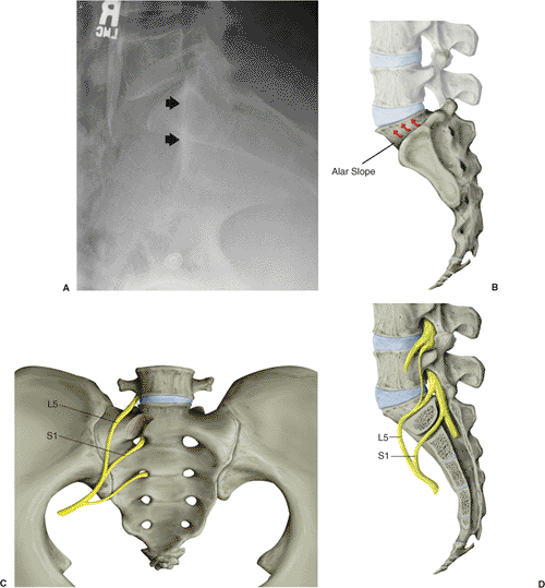
Figure 39.11. A.
The true-lateral sacral image is obtained only after accurate posterior-pelvic reduction has been visualized by superimposed greater-sciatic notches. The iliac cortical density is noted by the arrowheads. B. The disarticulated SI joint and the ascending sacral-alar slope. C. The local nerve roots and their alar relations are demonstrated. D. The lateral sacral sagittal section indicates the changing structure of the alar zone and its neural relations. The fifth lumbar and first sacral nerve roots are highlighted. |
construct is stressed under fluoroscopic imaging. Additional screws or
supplementary fixation are used if residual instability is noted on the
fluoroscopic stress examination. The percutaneous wound is irrigated,
and the skin is closed.
technician must work diligently to provide reproducible pelvic imaging.
Positioning the fluoroscopic unit in the marked position for each view
saves operative time and radiation exposure. The technician, who should
be preoperatively planning, should be informed about the imaging
requirements. Suboptimal imaging precludes placement of percutaneous
iliosacral screws.
to allow insertion of an additional ipsilateral screw or a screw from
the contralateral side if needed. The number of iliosacral screws
necessary to stabilize sufficiently each posterior-pelvic disruption
depends on the degree of local instability as well as the quality of
supplementary fixation of the associated pelvic-ring injuries.
Compression lag screws are routinely used to treat SI-joint
disruptions, but fully threaded screws can be used if a perfect
reduction has been achieved and no further compression is needed.
Sacral fractures may involve the sacral neuroforamina or alar area of
the fifth lumbar nerve root; therefore, further compression with a lag
screw may produce nerve root injury. For a transforaminal sacral
fracture, a fully threaded noncompression cancellous screw is required.
than those used for SI joints because the sacral fracture is more
medially located (Fig. 39.12). To obtain
optimal stability through improved medial fixation, the sacral screw
must be oriented more horizontally and tends to cross the chondral SI
surfaces.
slightly different for sacral screws than it is for SI-joint screws. SI
joint screws begin caudad and posterior on the ilium and are directed
cephalad and anterior to be perpendicular to the oblique SI
articulation. Because of its direction, this screw usually avoids
violation of the articular, SI-joint, cartilaginous surfaces.
roots must be understood and respected. The nerves exit the spinal
canal and are directed anteriorly, laterally, and caudally. Because of
this nerve orientation, the “safe” zone for screw insertion becomes the
elliptical
area within the ala below the fifth lumbar nerve-root pathway on the
mid-alar cortical bone and above the first sacral nerve root tunnel. A
pelvic model and preoperative drawing outlining the surgical tactic are
helpful. A pelvic model also reveals the smaller area available for
safe screw placement in the second sacral segment.
|
Table 39.1. The Differences between Iliosacral Screws Used for Sacroiliac Joint Dislocations and Sacral Fractures
|
||||||||||||||||||||||||||||||||||||
|---|---|---|---|---|---|---|---|---|---|---|---|---|---|---|---|---|---|---|---|---|---|---|---|---|---|---|---|---|---|---|---|---|---|---|---|---|
|
||||||||||||||||||||||||||||||||||||
 |
|
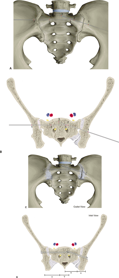
Figure 39.12. A,B. These illustrations demonstrate the screw orientations for sacral fractures (right side) and SI disruptions (left side). Critical fluoroscopic imaging intervals are numerically labeled. C,D.
The screws are oriented according to the injury. The SI joint is anatomically oblique, whereas most sacral fractures occur in a sagittal plane. Sacral fractures are medially located relative to SI joint injuries. For these two reasons, screw orientation and length are different for each. The screws are inserted perpendicular to the injury; therefore, sacral and SI screws are oriented differently. Sacral-screw orientation is more horizontal, which orients the screw perpendicular to the fracture and allows longer screw length to balance the fixation. SI screws are oriented obliquely to remain perpendicular to the disrupted joint surfaces. |
 |
|
Figure 39.13.
Iliosacral fixation failure occurs for a variety of reasons. In this patient with associated pelvic ring, acetabular, and urethral injuries, the anterior surgical wound was complicated with a deep infection. The complication resulted in anteriorly located implant disengagement, acetabular fracture displacement, and bending failure of the iliosacral screw. |
after surgery when percutaneous fixation has been used alone or in
combination with anterior-pelvic external fixation. If open techniques
are used, the antibiotics are continued until the surgical drains are
removed. Sequential compression stockings are used to diminish the risk
of deep venous thromboses. At my institution, a licensed physical
therapist supervises the rehabilitation. The rehabilitation schedule is
dependent on the overall condition of the patient and associated
injuries. The stabilized hemipelvis is protected by partial weight
bearing that the patient accomplishes with crutches or a walker for 6
weeks after the surgery. Progressive weight bearing follows, with a
goal of crutch-free ambulation 3 months after surgery. Inlet and outlet
radiographs of the pelvis are obtained in the recovery room and at the
6- and 12-week postoperative clinic visits. A postoperative CT scan is
used to assess the reduction and implant location. Patients are seen in
the clinic at 2, 6, and 12 weeks after the operation. Thereafter,
patients are seen annually and as needed.
6 months after surgery. Some patients with less physically demanding
jobs return much sooner, and others require job modifications. Heavy
lifting and working at heights are avoided until the patient’s strength
and conditioning goals are achieved. Vocational reeducation is
advocated for polytraumatized individuals with heavy job demands or
those patients who are unable to return to work. Nonimpact aerobic and
water activities are allowed 6 weeks after the operation.
malposition, iatrogenic nerve injury, fixation failure, and infection.
Screw malposition results from a poor understanding of the posterior
pelvic anatomy or fluoroscopic imaging or both, or posterior pelvic
malreduction. Iatrogenic nerve-root injuries occur because of erroneous
reduction maneuvers, especially overcompression of transforaminal
sacral fractures and screw-placement errors. The sacral alar slope,
inadequate imaging, sacral dysmorphism, a surgeon’s poor understanding
of the posterior pelvis, and posterior pelvic malreduction (among other
factors) cause screw misplacements. Surgeon knowledge of simple
anatomical, imaging, and technical facts can dramatically decrease the
risk of screw malposition:
-
The upper-sacral alar area is an
elliptically shaped passageway bounded above by the sloping sacral ala
and below by the upper-sacral nerve-root tunnel. -
The boundaries of the upper-sacral alar
area are identifiable radiographically after reduction. The outlet
images demonstrate the spica cast orientation of the upper-sacral
nerve-root pathway, and the true-lateral sacral image shows the
superimposed ICDs, which reflect the alar orientation, and as a
consequence, the fifth lumbar nerve-root path is also revealed. The
true lateral image is also frequently used to visualize the corticated
limit of the upper-sacral nerve-root path. -
The iliac starting point, directional aim, and selected screw length all impact the safety of screw placement.
-
Dysmorphic upper-sacral anatomy has
predictable radiographic identifiers, and the surgeon should recognize
the narrowed safe zone available for screw insertion. -
Obliquely oriented SI-joint screws must not extend beyond the midline because of the contralateral alar anatomy.
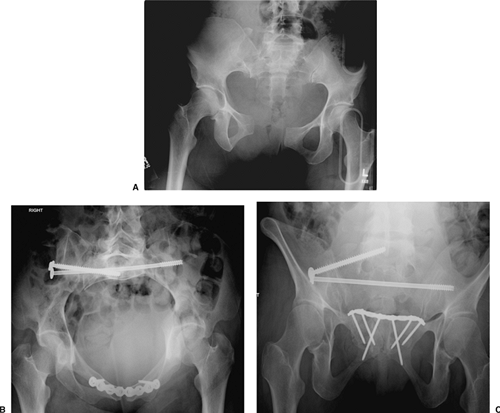
![]() Figure 39.14. A.
Figure 39.14. A.
This female adult patient was injured while riding her motorcycle. She
complained of pelvic pain and was noted to have an unstable pelvis
without peripheral neurological abnormalities. The screening AP plain
film of her pelvis demonstrates a complete symphysis pubis disruption
and a complex right-sided posterior pelvic-ring injury including SI
dislocation and sacral fracture. Upper-sacral dysplasia was noted the
outlet film and was confirmed by CT scan. She was resuscitated and then
taken to the operating room for pelvic stabilization. B.
In surgery, she underwent ORIF of the symphysis pubis, but the
posterior pelvic injury remained distracted despite accurate reduction
of the symphysis. For that reason and accommodating the upper-sacral
dysplasia, percutaneous reduction and fixation of the posterior pelvic
ring was the selected technique. The second sacral-segment lag screw
was inserted initially and slowly tightened under fluoroscopic imaging
to prevent overcompression of the fracture. The screw was applied into
the contralateral hemipelvis in an attempt to improve stability. Next,
the upper-sacral fully threaded screw was inserted percutaneously to
solidify further the posterior ring fixation. The postoperative inlet
image of her pelvic shows the reductions of the anterior and posterior
pelvic-ring injuries. C. The postoperative
outlet image of the pelvis demonstrates the different pathways
necessary for the upper-sacral and second-sacral segment screws. -
On the inlet image, lumbosacral osteophytes accentuate the anterior sacrum, but they do not represent the sacral body.
-
Neurodiagnostic monitoring does not
offset insufficient knowledge of sacral anatomy and its imaging.
Iatrogenic nerve-root injuries occur because of screw placement errors
and erroneous reduction maneuvers, especially overcompression of
transforaminal sacral fractures.
posterior-pelvic injuries, who are noncompliant or have suffered head
injuries, or have an associated infection. Increased rates of fixation
failure have been described in those patients treated with iliosacral
screws and anterior external fixation (Fig. 39.13).
numerous factors. In early failures, the unstable iliosacral screws are
removed, and alternative fixations are performed after repeated
reductions. The treatment of late failures is based on the amount of
posterior pelvis displacement and healing. In rare situations, the
overall condition of the patient or posterior pelvic soft-tissue
envelope prohibits further attempts at surgical fixation, and
traditional management techniques, such as traction, are chosen. Deep
infection is rarely associated with percutaneous iliosacral-screw
insertion.
accident. The radiographs and CT scan of the pelvis showed a symphysis
pubis disruption, a complex SI dislocation, and an ipsilateral sacral
fracture (Fig. 39.14).
however, her neurological status was normal. She was evaluated and
resuscitated. With urgency, she was brought to the operating room and
positioned supine. She was placed in 15 lb of right-sided
distal-femoral traction. Through the surgeon’s use of a Pfannenstiel
exposure, the anterior symphyseal injury was reduced, clamped, and
fixed with a plate and screws. The posterior-pelvic
fracture-dislocation reduction was improved after the symphyseal open
reduction and fixation along with distal femoral traction. Percutaneous
iliosacral screws were used to stabilize the posterior pelvic injuries.
She had an upper-sacral dysmorphism that complicated safe screw
insertion. The postoperative CT scan and plain films identified the
implant locations and reduction quality. Her recovery was uneventful.
An attorney, she returned to work.
C, Coons D, Tornetta P, et al. Standard multiplanar fluoroscopy versus
a fluoroscopically based navigation system for the percutaneous
insertion of iliosacral screws: a cadaver model. J Orthop Trauma 2005;19:254–258.
DR, Starr AJ, Reinert CM, et al. Vertically unstable pelvic fractures
fixed with percutaneous iliosacral screws: does posterior injury
pattern predict fixation failure? J Orthop Trauma 2003;17:399–405.
GS, Leit ME, Gruen RJ, et al. The acute management of hemodynamically
unstable multiple trauma patients with pelvic ring fractures. J Trauma 1994;36:706–713.
DL, Koval KJ, Hissa EA, et al. Intraoperative somatosensory evoked
potential monitoring during acute pelvic fracture surgery. J Orthop Trauma 1995;9:28–34.
CW, Twaddle B, Agel J, et al. Outcome after pelvic ring fractures:
evaluation using the medical outcomes short form SF-36. Injury 1996;27:635–641.
MLC Jr, Kregor PJ, Simonian PT, et al. Early results of percutaneous
iliosacral screws placed with the patient in the supine position. J Orthop Trauma 1995;9:207–214.
MLC Jr, Simonian PT, Agnew S, et al. Radiographic recognition of the
sacral alar slope facilitates optimal placement of iliosacral screws: a
cadaveric and clinical study. J Orthop Trauma 1996;10:171–177.
TA, Ledoux WR, Chapman JR, et al. Triangular osteosynthesis and
iliosacral screw fixation for unstable sacral fractures: a cadaveric
and biomechanical evaluation under cyclic loads. J Orthop Trauma 2003;17:22–31.
T, Boone D, Gruen G, et al. Percutaneous iliosacral screw fixation:
early treatment for unstable posterior pelvic ring disruptions. J Trauma 1995;38:453–458.
PT, Routt MLC Jr, Harrington RM, et al. Anterior versus posterior
provisional fixation in the unstable pelvis: a biomechanical
comparison. Clin Orthop 1995;310:245–251.