
address fractures, dislocations, ligamentous injuries, arthritis, and
other pathology such as congenital anomalies or neoplasms (1, 2, 3).
Moreover, one can perform compartment releases, tenosynovectomy, and
posterior interosseous nerve (PIN) neurectomy through a dorsal approach
(1,4).
The dorsal aspect of the wrist is characterized by a loose skin and
subcutaneous tissue. A thin superficial fascia covers the dorsal aspect
of the wrist and hand including fatty and fibrous layers, cutaneous
nerves, and venous and lymphatic vessels. When approaching the wrist
joint, the vessels should be preserved whenever possible to facilitate
venous return from the hand which is largely dependent upon these
cutaneous vessels (3). The dorsal nerves and
subcutaneous veins should be raised in continuity with the skin and
subcutaneous tissues. The dorsal aspect of the hand is supplied by
branches of the superficial branch of the radial nerve and the dorsal
sensory branch of the ulnar nerve in a variable pattern with an
inconsistent contribution of the lateral and posterior antebrachial
cutaneous nerves (5, 6, 7).
These cutaneous nerves should be identified and preserved. Use of
vessel loops to isolate and protect the nerves may be helpful.
encountered. The wrist and finger extensors travel beneath the extensor
retinaculum in six dorsal compartments, delineated by fibrous septae
attaching from the extensor retinaculum to the periosteum of the
radius. Palmer et al investigated the anatomy and biomechanical role of
the extensor retinaculum of the wrist (8). This
fibrous thickening of the antebrachial fascia lies in a band over the
dorsal aspect of the wrist joint and is continuous with the volar
carpal ligament palmarly and the dorsal fascia over the distal hand and
metacarpal region (8). Fibrous septae
traversing from the retinaculum palmarly to insert upon the radial
periosteum or wrist capsule create five fibro-osseous tunnels and one
fibrous canal, the 5th compartment. From radial to ulnar, the
compartments are as follows: first dorsal compartment: abductor
pollicis longus and extensor pollicis brevis; second dorsal
compartment: extensor carpi radialis longus and brevis; third dorsal
compartment: extensor pollicis longus; fourth dorsal compartment:
extensor digitorum communis and extensor indicis proprius; fifth dorsal
compartment: extensor digiti minimi; and sixth dorsal compartment:
extensor carpi ulnaris.
wrist joint. The capsule is comprised of ligamentous tissue and
nonligamentous tissues. The major dorsal wrist ligaments are the dorsal
radioulnar ligament, the dorsal radiocarpal ligament, and the dorsal
intercarpal ligament. The dorsal radioulnar ligament spans from the
radius at the dorsal margin of the sigmoid notch over the distal
radioulnar joint (DRUJ) to attach to the head of the ulna and along the
styloid process. It contributes to the extensor carpi ulnaris subsheath
and the triangular fibrocartilaginous complex (TFCC). Similarly, the
dorsoradioulnar ligament attaches to the radius at a site ulnar to the
Lister’s tubercle then spans the radiocarpal joint obliquely to attach
to the dorsal horn of the lunate and to form the lunotriquetral
interosseous ligament superficially. The dorsal intercarpal ligament is
confluent with the dorsal radiocarpal ligament at their insertions upon
the triquetrum. It courses distally and obliquely from the triquetrum
to the dorsal ridge of the distal half of the scaphoid and to the
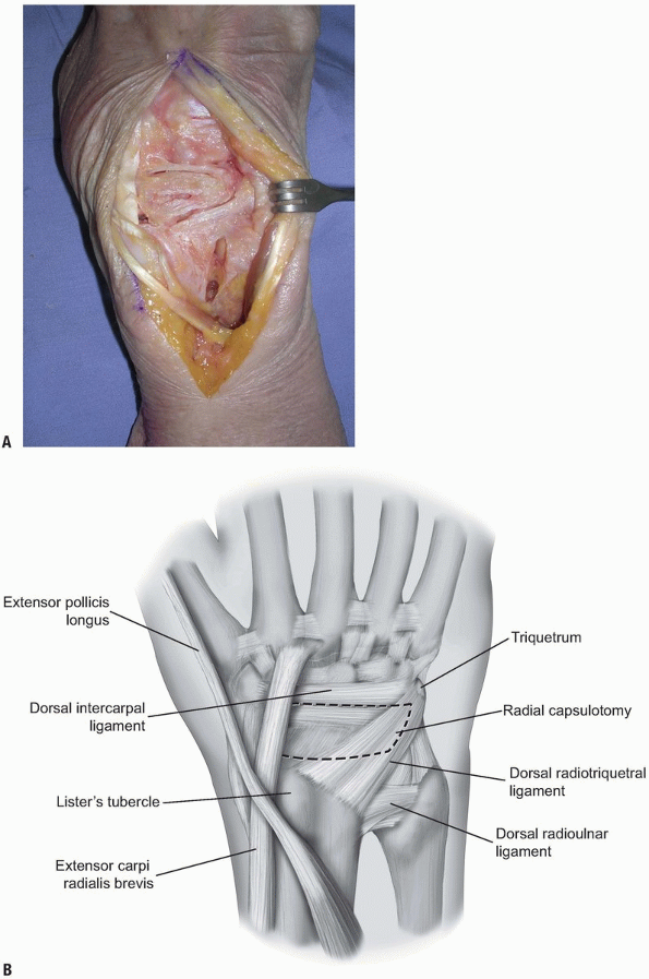
dorsal cortex of the trapezoid (2). To expose
the dorsal aspect of the wrist, a dorsal capsular flap (the Mayo flap)
can be raised by elevating a split dorsal radiotriquetral and dorsal
intercarpal ligament with a radial based flap.
lies in a lateral position when the hand and forearm are in the
anatomic position. The ulnar styloid process is medially and
posteriorly located when the hand and forearm are in the anatomic
position. The extensor carpi ulnaris (ECU) lies in a dorsal groove
radial to this landmark. Distally, the eight carpal bones are aligned
in two rows. The anatomic snuff box is outlined when the thumb is
abducted. The scaphoid bone lies in the floor and ulnar deviation of
the wrist causes it to slide outward from beneath the radial styloid to
become palpable. Lister’s tubercle or the dorsal tubercle of the radius
lies about one third the distance across the dorsum of the wrist from
the radial styloid. The scaphoid-lunate junction (and scapholunate
ligament) is located just distal to Lister’s tubercle. The capitate
lies at the base of the 3rd metacarpal bone. When the wrist is in a
neutral position, the depression in the capitate becomes palpable (9).
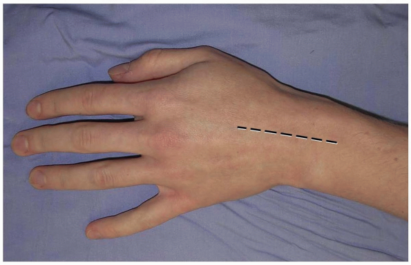
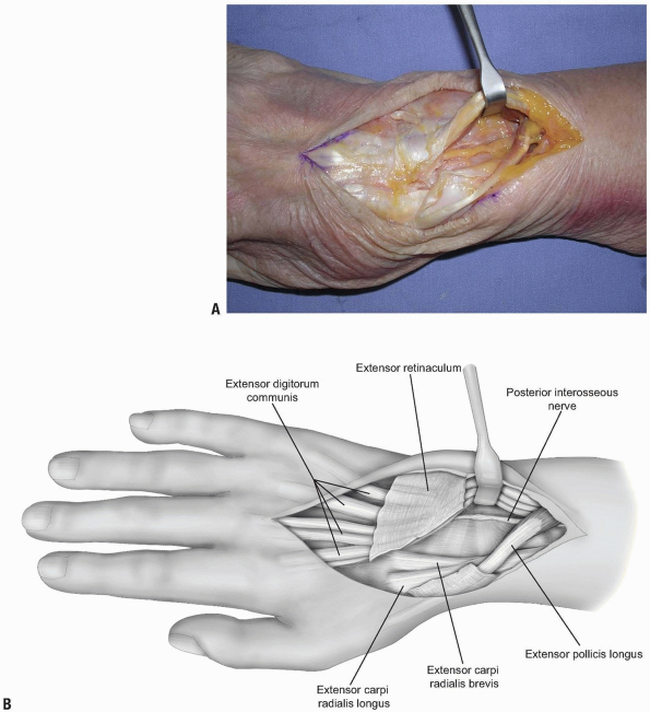
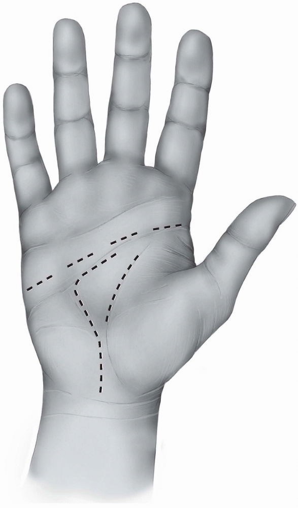
prefer a longitudinal incision that may be extended distally and
proximally (3,10) (Fig. 1-1).
The incision may be centered in the radial and ulnar dimension and
extends longitudinally from 2 to 3 cm proximal to the radiocarpal joint
to 2 cm distal to Lister’s tubercle, depending on the pathology to be
addressed. Although not in Langer’s lines and indeed, the longitudinal
incision is perpendicular to Langer’s lines, incisional contracture is
not problematic as the skin overlying the dorsum of the wrist is quite
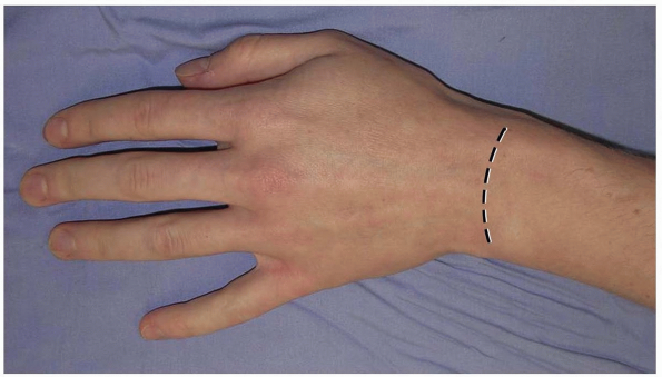
pliable and longitudinal scarring is uncommon. Alternatively, a
transverse slightly curved incision, directed in line with Langer’s
lines, with the concavity oriented distally may be used (2) (Fig. 1-2).
This incision can extend from the radial styloid to the ulnar styloid,
in which case mobilization of the incision allows for exposure of the
carpometacarpal joints and the distal radial metaphysis (2).
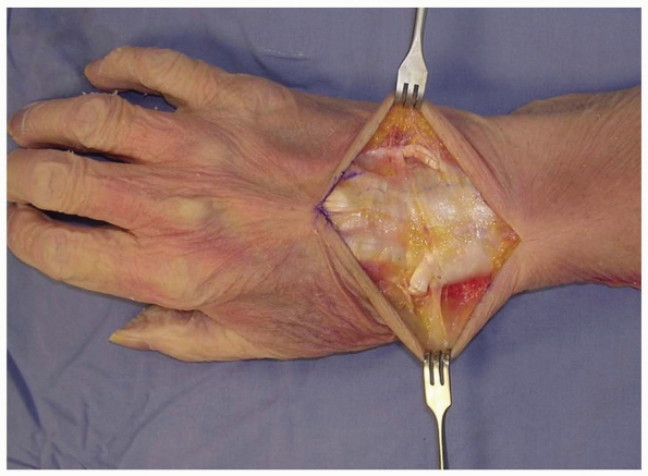
taking care to identify and preserve the superficial radial nerve, the
dorsal sensory branch of the ulnar nerve, and any dorsal veins, and
elevating them with the flaps (2,3).
This is in contradistinction to the practice on the palmar aspect of
the hand, where skin flaps are raised and elevated away from the
neurovascular structures.
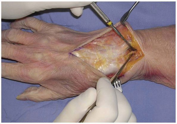
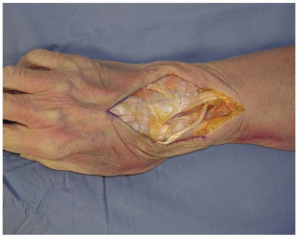
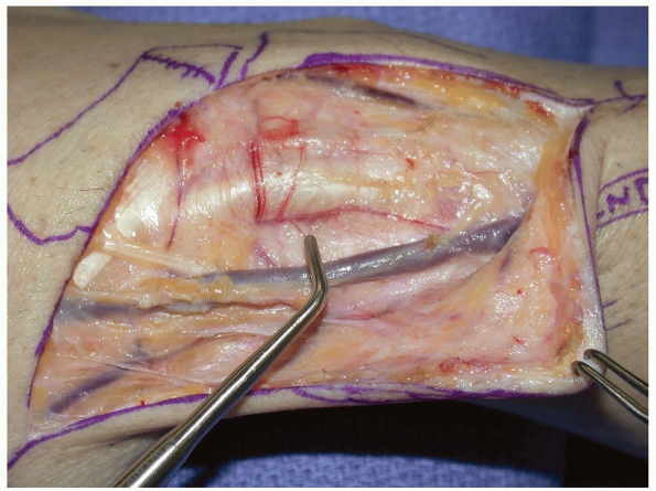
tendons, the retinaculum over the desired compartment is incised. If a
posterior interosseous nerve (PIN) neurectomy is to be performed, a
deeper dissection is made 2 cm proximal to the extensor retinaculum (11) (Fig. 1-4).
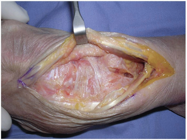
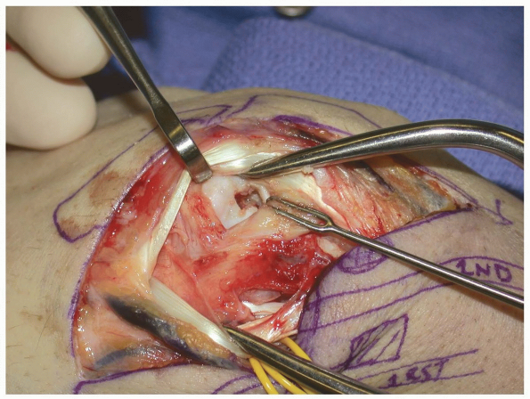
The dissection proceeds through the deep fascia of the forearm. The PIN
is identified as it enters the 4th extensor compartment and a 2 cm
segment of the nerve, which is purely sensory at this level, is excised
(11) (Figs. 1-4 and 1-5).
The PIN and posterior interosseous artery course longitudinally from
proximal to distal. Proximally, the PIN innervates the extensor
pollicis longus (EPL) and extensor indicis proprius (EIP). At this
level, it departs from the posterior interosseous artery and travels
distally bound under a fascial layer to the interosseus membrane along
the ulnar border of the radius (4). At the
level of the Lister’s tubercle, the PIN lies adjacent to the ulnar
origin of the 3rd dorsal compartment. It then travels distally with the
anterior interosseus artery across the radiocarpal joint. At the level
of the scapholunate ligament, the PIN branches into its terminal
extensions to bring sensory and proprioceptive nerve fibers to the
capsule and ligaments of the dorsal aspect of the wrist (4).
By denervating the PIN (and anterior interosseus nerve [AIN]), pain
related to the scapholunate ligament and adjacent capsule may be
attenuated.
 |
|
FIGURE 1-1 A longitudinal incision centered over the wrist is preferred. Incisional contractures are rarely problematic.
|
 |
|
FIGURE
1-2 An alternative transverse incision in Langer’s lines. This incision can extend from the radial styloid to the ulnar styloid, in which case mobilization allows for exposure of the carpometacarpal joints and the distal radial metaphysis. |
 |
|
FIGURE
1-3 Full-thickness flaps are developed down to the extensor retinaculum, taking care to identify and preserve the superficial radial nerve, the dorsal sensory branch of the ulnar nerve, and any dorsal veins, and elevating them with the flaps. EDC (extensor digitorum comminus), EDM (extensor digiti minimi), EPL (extensor pollicis longus). |
 |
|
FIGURE
1-4 The posterior interosseous nerve (PIN) may be exposed for neurectomy by dissection 2 cm proximal to the extensor retinaculum. |
 |
|
FIGURE 1-5 A,B:
The PIN is identified as it enters the 4th extensor compartment and a 2 cm segment of the nerve, which is purely sensory at this level, is excised to achieve PIN neurectomy. |
overlying the 3rd dorsal compartment is incised longitudinally from the
deep antebrachial fascia proximally and then distally to the distal
margin of the retinaculum (Fig. 1-6).
The EPL in the 3rd dorsal compartment is retracted radially, and the
4th extensor compartment is elevated subperiosteally or by dividing the
septum between the 3rd and 4th compartments and reflecting the
retinaculum as an ulnarly based flap (Fig. 1-7).
The approach is limited by the septum between the 5th and 6th dorsal
compartments. Radially, the extensor retinaculum may be elevated off of
Lister’s tubercle and the 2nd dorsal compartment released.
Subsequently, the extensor carpi radialis brevis (ECRB) and extensor
carpi radialis longus (ECRL) can be retracted radially deep to the
extensor retinaculum, with the EPL retracted radially and superficial
to the extensor retinaculum. This allows for exposure of approximately
90% of the dorsal wrist (2) (Fig. 1-8).
access to the pathology to be addressed. Care should be taken when
planning the capsulotomy to access the wrist joint. A poorly designed
capsulotomy may destabilize the joint by disrupting the dorsal capsular
ligaments, result in limited range of motion due to scar formation, or
leave inadequate remaining tissue to facilitate closure (2).
While some surgeons advocate a simple transverse or longitudinal
capsulotomy in line with the skin incision (and these may be adequate
in revision surgery, subtotal or complete wrist fusion, or in other
cases) (1,3,10), we prefer a ligament-sparing capsulotomy with capsulotomy incisions parallel to the dorsal wrist ligaments.
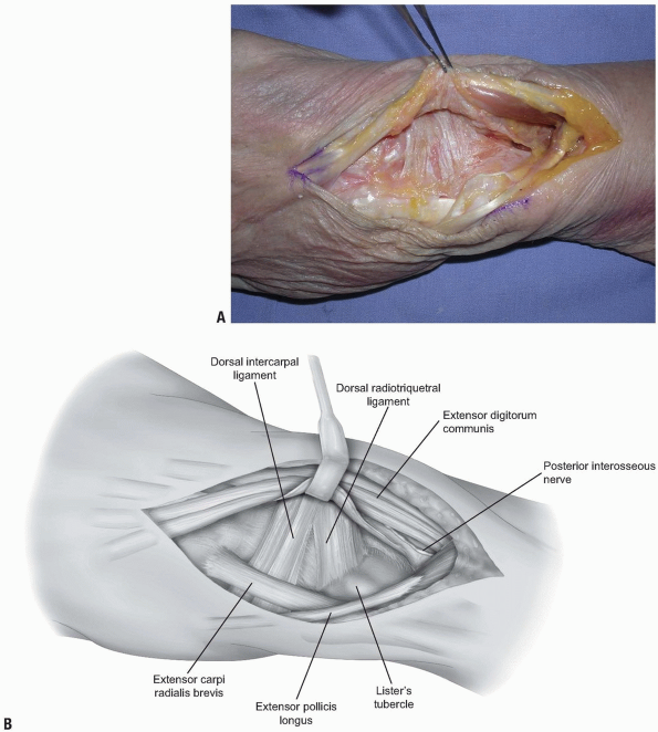
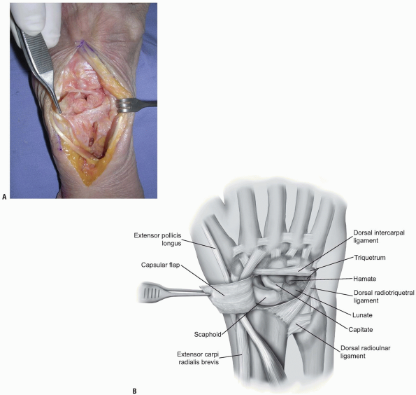
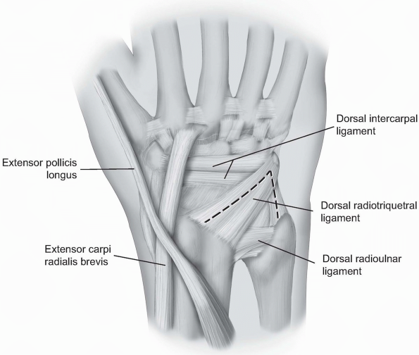
two-thirds of the radiocarpal joint and most of the midcarpal joint.
The fibers of the dorsal radiocarpal and dorsal intercarpal ligaments
are incised in line with their fibers in the midline of each ligament (Fig. 1-9)
with continuation along the dorsal rim of the radius toward the radial
styloid process to generate a three-sided trapezoidal flap remaining
attached on the radial side. The flap of capsule is then elevated
sharply off the dorsal surface of the triquetrum then off the lunate
and scaphoid, with care taken to avoid injury to the lunotriquetral and
scapholunate interosseous ligaments (Fig. 1-10). Elevation is halted upon encountering the dorsal ridge of the scaphoid to avoid damage to the vascular supply of the scaphoid.
 |
|
FIGURE
1-6 To gain access to the wrist joint, the retinaculum overlying the 3rd dorsal compartment is incised longitudinally from the deep antebrachial fascia proximally and then distally to the distal margin of the retinaculum. |
 |
|
FIGURE 1-7 A,B:
The EPL in the 3rd dorsal compartment is retracted radially, and the 4th extensor compartment is elevated subperiosteally or by dividing the septum between the 3rd and 4th compartments and reflecting the retinaculum as an ulnarly based flap. |
 |
|
FIGURE
1-8 The ECRL can be retracted radially deep to the extensor retinaculum, with the EPL retracted radially and superficial to the extensor retinaculum. This allows for exposure of approximately 90% of the dorsal wrist. |
 |
|
FIGURE 1-9 A,B:
The fibers of the dorsal radiocarpal and dorsal intercarpal ligaments are incised in line with their fibers in the midline of each ligament, with continuation along the dorsal rim of the radius toward the radial styloid process to generate a three-sided trapezoidal flap remaining attached on the radial side. The flap of capsule is then elevated sharply off the dorsal surface of the triquetrum then off the lunate and scaphoid, with care taken to avoid injury to the lunotriquetral and scapholunate interosseous ligaments. |
 |
|
FIGURE 1-10 A,B:
Elevation of capsular flaps in this manner preserves the blood supply and allows for closure of tissues following the procedure. |
visualization of the lunate, the scaphoid, the scapholunate ligament,
the dorsal aspect of the radiocarpal joint, the lunotriquetral joint,
the proximal capitate and triquetrum, and the hamate. Mobilization
radially allows for access to the proximal trapezoid, trapezium and STT
joint. Distraction of the wrist allows for access to the palmar joint
capsule of the radiocarpal joint and the midcarpal ligaments (2).
Closure of the capsule is facilitated using 3-0 braided absorbable
sutures in a figure of eight or horizontal mattress pattern (2).
triquetrum and the ulnar aspect of the radiocarpal joint. The skin and
subcutaneous dissection may proceed as outlined above for the
capsulotomy to the radial aspect of the joint (2). Alternatively, only the ulnar half of the transverse incision
may be made with dissection proceeding to the extensor retinaculum
where the 5th extensor compartment is incised and the EDM retracted
ulnarly. To expand the exposure, the septum between the 4th and 5th
dorsal compartments may be incised, the 4th compartment entered and the
extensor digitorum communis (EDC) and EIP tendons retracted radially.
 |
|
FIGURE
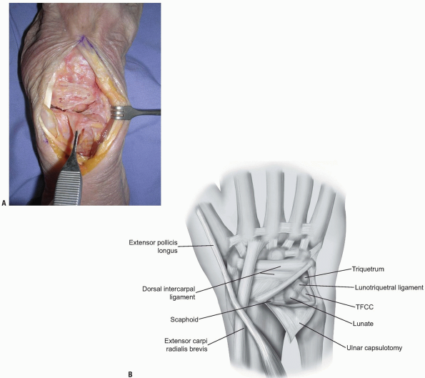
1-11 For the ulnar capsultomy, the dorsal radiocarpal ligament is incised longitudinally through its midline. The dorsal radioulnar ligament is preserved as are the 6th extensor compartment and the ECU subsheath. |
compartments is identified at the level of the triquetrum and reflected
ulnarly or the ulnar part of the extensor retinaculum is released
radial to ulnar from Lister’s tubercle to the 6th extensor compartment.
The dorsal radioulnar ligament is preserved as are the 6th extensor
compartment and the ECU subsheath. A proximally based triangular flap
is elevated sharply from the triquetrum and the lunate, until the
distal extent of the dorsal radioulnar ligament is encountered (Fig. 1-12).
Synovial tissue is removed to expose the lunate, the lunotriquetral
interosseous ligament, the triquetrum, and the triangular
fibrocartilage complex (Fig. 1-13).
Wrist distraction provides access to the ulnolunate and ulnotriquetral
ligaments. Following completion of work, capsular closure is performed
in the usual fashion with interrupted figure of eight or horizontal
mattress sutures with 3-0 braided absorbable sutures (2).
procedures to address pathology of the carpus, the extensor tendons,
the PIN, or fractures. The subcutaneous location makes this approach
readily available and relatively simple. Attention to ligament sparing
capsulotomy can preserve stability and motion in certain cases.
 |
|
FIGURE 1-12 A,B:
A proximally based triangular flap is elevated sharply from the triquetrum and the lunate, until the distal extent of the dorsal radioulnar ligament is encountered. |
 |
|
FIGURE
1-13 Synovial tissue is removed to expose the lunate, the lunotriquetral interosseous ligament, the triquetrum, and the triangular fibrocartilage complex. |
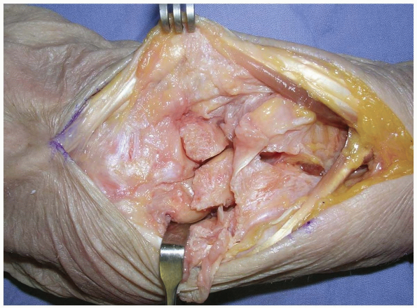
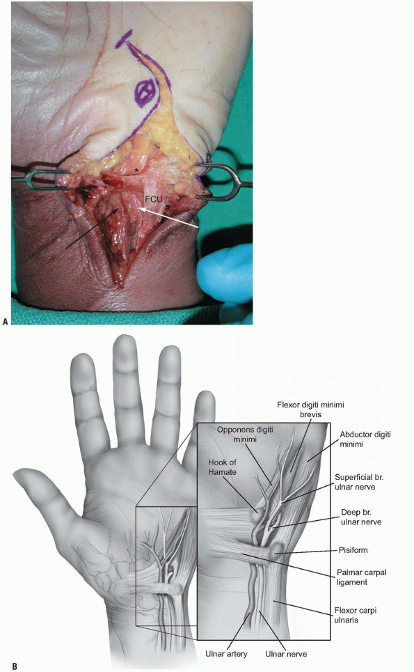
forearm under the muscle and the tendon of the flexor carpi ulnaris
(FCU) with the ulnar artery being on its radial side. Just before the
wrist crease, the ulnar artery and nerve emerge from under the muscle
and enter the distal ulnar tunnel canal in the wrist. At this level,
the ulnar artery and nerve are located on the radial surface of the FCU.
It is essentially a triangular fibro-osseous tunnel about 3 cm long
located at the carpus. The volar carpal ligament forms the roof of the
canal, which is a condensation of the forearm fascia and expansion of
the FCU. The transverse carpal ligament, extending between the pisiform
and the hook of the hamate, forms the floor of the canal. The hook of
the hamate and the medial side defines the lateral side of the canal by
the pisiform. The contents of the distal ulnar tunnel are the ulnar
nerve, the ulnar artery, and the ulnar veins.
located quite superficially, exactly below the skin and the
subcutaneous tissue. The respective roof of the neighboring carpal
tunnel, the transverse carpal ligament, is the floor of the Guyon’s
canal and is a relatively thick fibrous layer.
angulated medially about 30 degrees to the long axis of the forearm and
the wrist, since the hook of the hamate lies a little more distal to
the pisiform.
wrist are traumatic injuries of the ulnar nerve, compression
neuropathies within the Guyon’s canal, and intrinsic muscle spasticity
requiring ulnar motor neurectomy.
exploration is performed in a bloodless field provided by a tourniquet.
The ulnar nerve can be explored through a volar approach, which is
located 1 to 2 cm more medially than the typical approaches for open
release of the carpal tunnel. A consideration in planning the skin
incision is the location of the palmar cutaneous branch of the ulnar
nerve. Although this nerve was found to be present in only 25% in
previous cadaveric studies (2), injury to it
can lead to painful neuromas. The ideal incision should be located in
the internervous plane between the palmar cutaneous branch of the ulnar
and median nerve. Unfortunately, cadaveric studies have identified that
there is not such a plane. This plane is innervated by the nerve of
Henle (the nerve of the ulnar artery) and multiple ulnar cutaneous
branches (3). Therefore, the dissection of the
skin and subcutaneous tissue should be performed carefully, possibly
under loop magnification, preserving any emerging cutaneous branches.
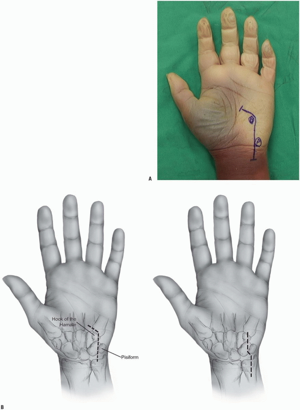
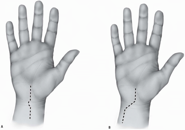
hamate, and the hypothenar eminence. The typical incision is
curvilinear in shape with the distal limb following the radial limb of
the hypothenar eminence and the proximal limb extending on the volar
ulnar part of the forearm. The wrist crease should not be crossed
longitudinally but rather in an angle of 60 degrees to avoid skin
contractures. The total length of the incision is about 6 to 8 cm
centered over the wrist crease (Fig. 1-14).
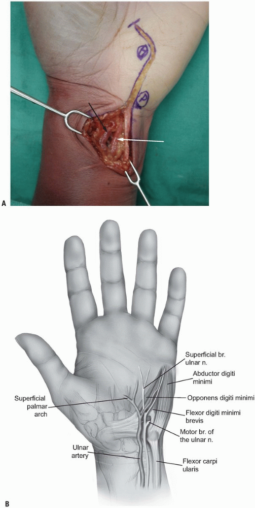
the proximal part of the incision where they lie on the lateral surface
of the tendon of the FCU (Fig. 1-15).
They can be traced easily distally incising all tissues more
superficial to these structures. The dissection of the subcutaneous fat
should be performed bluntly in order to avoid injury to any cutaneous
branches. The palmaris brevis muscle is elevated slightly ulnarly and
the volar carpal ligament and pisohamate ligament are incised resulting
in a complete decompression of the Guyon’s canal. The two branches of
the ulnar nerve at the level of the pisiform are identified.
 |
|
FIGURE 1-14 A,B:
Incisions for the exploration of the ulnar nerve. At the level of the wrist, the incisions pass radial to the pisiform and ulnar to the hook of the hamate. |
 |
|
FIGURE 1-15 A,B: The ulnar artery (white arrow) and the ulnar nerve (black arrow) are identified at the radial margin of the flexor carpi ulnaris tendon.
|
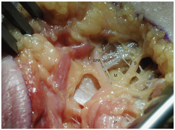
level of the bifurcation. It can be traced beneath the fibrous arch of
the hypothenar muscles formed between the abductor digiti minimi and
the flexor digiti minimi, through the muscle mass of the opponens
digiti minimi and around the hook of the hamate. A careful exploration
of the floor of the distal ulnar tunnel is performed looking for any
pathology like ganglions, fibrous bands, anomalous muscle masses,
fractures of the hook of the hamate, and vascular aneurysms.
wound and the ulnar artery and its branches should be examined for any
injury. Thorough hemostasis should be achieved since a post-operative
hematoma can result in compression neuropathy of the ulnar nerve.
carpal tunnel syndrome incision extending slightly more proximally and
distally. The ulnar nerve and artery are located on the volar medial
surface of the transverse carpal ligament and can be identified tracing
the superficial palmar arch proximally. Several hand surgeons prefer to
decompress the Guyon’s canal and the carpal tunnel simultaneously.
branches, the superficial and the deep branch. The superficial branch
gives immediately after the bifurcation motor branches to the palmaris
brevis muscle and becomes purely sensory. It continues its course
distally deep and medial to the ulnar artery providing sensory supply
to the small finger and the ulnar side of the ring finger. The deep
branch of the ulnar nerve bifurcation is purely motor and supplies the
hypothenar muscles, all the interossei, the medial two lumbricals, and
the adductor pollicis. The motor part of the ulnar nerve is located
dorsally in the ulnar nerve at the level of the distal forearm and
emerges from the nerve on the dorsal medial surface. The motor branch
leaves the tunnel and passes beneath the fibrous arch of the hypothenar
muscles and enters the interval between the abductor digiti minimi and
flexor digiti muscles. It pierces the opponens digiti minimi and curves
radially and dorsally around the distal part of the hook of the hamate,
lying on the floor of the carpal tunnel (Fig. 1-16).
syndrome is less common because the space within the Guyon’s canal is
much more yielding. Compression within the canal can produce motor or
sensory or combined motor and sensory symptoms. The Guyon’s canal can
be divided in three zones to allow more accurate localization of the
pathology of the compression in respect to the neurological symptoms (4).
radially by the volar carpal ligament, medially by the FCU and the
pisiform, and dorsally by the transverse carpal ligament. This region
includes both the sensory and the motor branches of the ulnar nerve;
therefore, compression in the region results in combined motor and
sensory deficits. Compressions within this region are usually produced
by fractures of the hook of the hamate and ganglions (Fig. 1-17).
 |
|
FIGURE
1-16 The deep motor branch of the ulnar nerve passes under the fibrous arch of the hypothenar muscles ulnar to the hook of the hamate. (P, pisiform; M, motor branch; SPA, ulnar branch to superficial palmar arch; FA, fibrous arch of the hypothenar muscles; S, one of the sensory branches of the ulnar nerve.) |
 |
|
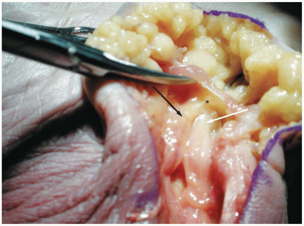
FIGURE 1-17 A,B:
Zone I of the ulnar tunnel as described by Gross and Gelberman (asterisk). Note the neurovascular bundle passing under the proximal edge of the palmar carpal ligament. (FCU, flexor carpi ulnaris; white arrow, ulnar artery; black arrow, ulnar nerve.) |
muscle and the fibrous arch of the hypothenar muscles; dorsally by the
pisiform and hamate ligaments and the oppenens digiti minimi; medially
by the superficial branch of the ulnar nerve and the abductor digiti
minimi; and laterally by the transverse carpal ligament, flexor digiti
minimi, and the hook of the hamate. This region surrounds the motor
branch of the ulnar nerve and compression within this region results in
motor symptoms. Ganglions and fractures of the hook of the hamate can
produce compression within this region, as well as anomalous intrinsic
muscles within the canal (Figs. 1-18 and 1-19).
palmaris brevis muscle, dorsally by the hypothenar fascia, laterally by
the motor branch of the ulnar nerve, and medially by the abductor
digiti minimi muscle. This region surrounds the superficial branches of
the ulnar nerve, and compression within this region produces
exclusively sensory symptoms (Fig. 1-19).
The most frequent causes of compression within this region are synovial
inflammation, vascular lesions of the ulnar artery (thrombosis,
aneurysm, or pseudoaneurysm), and anomalous size and location of
abductor digiti minimi.
 |
|
FIGURE
1-18 Demonstrates the entrance to zone II of the ulnar tunnel in which the nerve passes under the palmar brevis muscle providing innervation to the muscle (asterisk). (White arrow, ulnar artery; black arrow, ulnar nerve.) |
 |
|
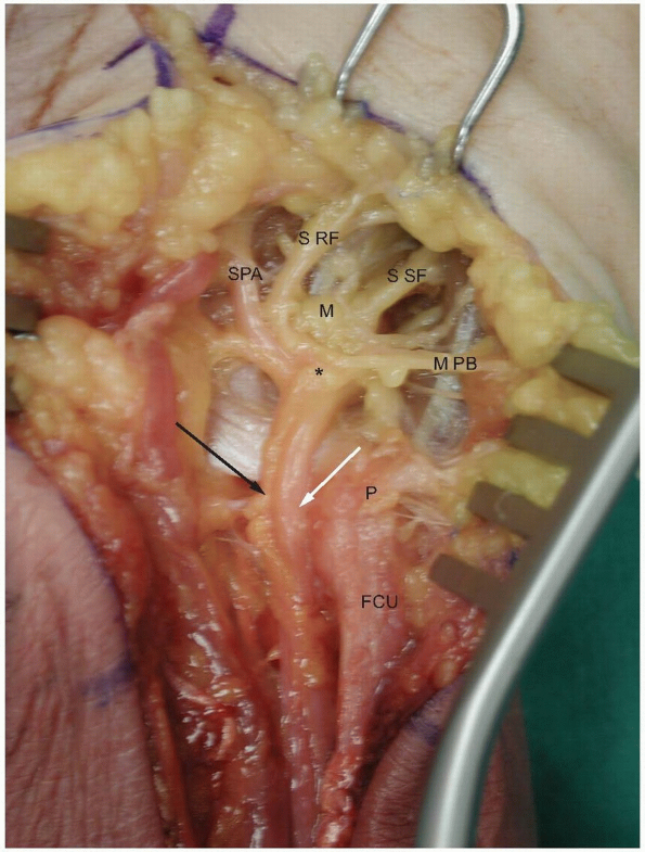
FIGURE
1-19 The ulnar nerve passes over the pisohamate and pisometacarpal ligaments which form the floor of the tunnel. Note the branches which supply the hypothenar muscles. The asterisk marks the nerve bifurcation into the deep motor branch (M) and the superficial sensory branches. (P, pisiform; FCU: flexor carpi ulnaris; white arrow, ulnar artery; black arrow, ulnar nerve; SPA, ulnar branch to superficial palmar arch; S RF, sensory branch to ulnar side of ring finger and radial side of the small finger; S SF, sensory branch to the ulnar surface of the small finger; M PB, motor branches to the palmaris brevis muscle.) |
extent, on the normal function of the flexor tendons. These collagenous
structures are able to transmit enormous forces from the muscles in the
forearm to the fingers allowing not only powerful motions but also fine
motor activities.
require prompt tendon surgery and accurate surgical approach. The same
approaches can be used to address clinical conditions affecting
neighboring structures like the nerves, the vessels, or the bones in
the hand.
surgery will be presented, as well as brief description of the anatomy
of the flexor tendons and of the special properties and considerations
of the volar skin of the palm and the fingers.
and provide the respective flexor tendons in the distal third of the
volar compartment of the forearm. Three flexor tendons insert around
the area of the wrist; the flexor carpi radialis located on the radial
side of the forearm inserts at the base of the second metacarpal; the
FCU located in the ulnar aspect of the forearm inserts at the pisiform
bone; the palmaris longus located in the most superficial layers along
the midline of the forearm inserts at the palmar fascia of the hand.
The palmaris longus is absent unilaterally or bilaterally in 12% and is
useful in grafting because it is readily accessible and expandable.
of the fingers and the thumb; two for each of the fingers and one long
flexor for the thumb. They all enter the hand through the carpal tunnel
and diverge towards the respective digit where they insert.
digitorum superficialis (FDS) and the flexor digitorum profundus (FDP).
The FDS tendons lie more anterior to the FDP within the forearm and the
palm and are grouped in two layers within the carpal tunnel. The
tendons of the middle and ring fingers lie volarly to those of the
index and small fingers. At the palm all the tendons of the FDS lie in
the same plane, volar to the tendons of the FDP.
usually not so distinct at the level of the palm with the exception of
the tendon to the index. They become more distinct distal to the carpal
tunnel. An important anatomical relationship helpful in distinguishing
the tendons of the FDP from the FDS in multiple tendon lacerations
within the palm is that the four lumbrical muscles take their origin
from the tendons of the FDP.
splits into bands. The FDP passes between these two bands becoming more
superficial to the FDS forming the Camper’s chiasm. The two bands of
the FDS rotate away from the midline so that the most medial fibers
become the most volar ones and the most lateral ones become the most
dorsal, and insert at the two lateral edges of the base of the middle
phalanx. The FDP continues more distally and inserts at the base of the
distal phalanx.
pollicis longus (FPL), which enters the carpal tunnel in its most
radial aspect. Following the carpal tunnel, the tendon courses around
the scaphoid, beneath the thenar musculature, and inserts at the base
of the distal phalanx of the thumb.
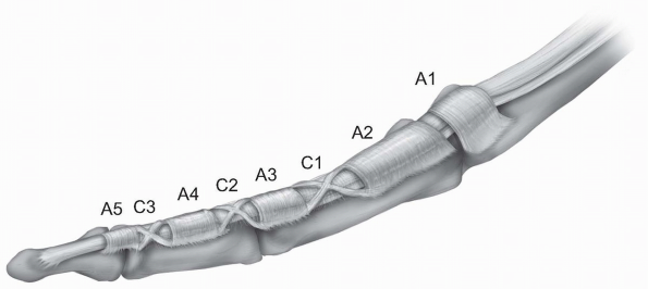
well-defined fibro-osseous tunnel just proximal to the respective
metacarpophalangeal joint of the finger. This digital fibrous sheath
consists of thick fibrous bands in oblique or transverse orientation,
known as pulleys, which keep the tendons close to the phalanges and
prevent bowstringing during flexion of the finger. The current
nomenclature for the pulley system was established by Doyle and Blythe (1,2),
who described five annular “A” (A1-A5) and three cruciate “C” (C1-C3)
pulleys. A1, A3 and A5 are located over the metcarpophalangeal,
proximal interphalangeal, and distal interphalangeal respectively. A2
and A4 are located over the middle part of the proximal and distal
phalanx respectively. The C1 pulley is over the distal end of the
proximal phalanx, the C2 pulley over the proximal end of the middle
phalanx, and the C3 pulley over the distal end of the middle phalanx (Fig. 1-20).
 |
|
FIGURE 1-20 The fibro-osseous tunnel of each finger with the annular A1-A5 and cruciate C1-C3 pulleys.
|
annular A1 pulley over the metacarpophalangeal joint, an oblique
annular ligament extending from proximal ulnar to distal radial
direction over the proximal phalanx of the thumb, and an annular A2
pulley over the interphalangeal joint.
sheath comes from two sources: diffusion and vascular perfusion from
the vincular system. Each tendon has a long and short vinculum, which
are folds of the mesotenon running from the dorsal portion of the
dorsal wall of the tendon sheath, emerging from the digital vessels.
The short vinculae of the FDS and FDP, which are located respectively
over the ends of the proximal and middle phalanges, are considered the
important ones.
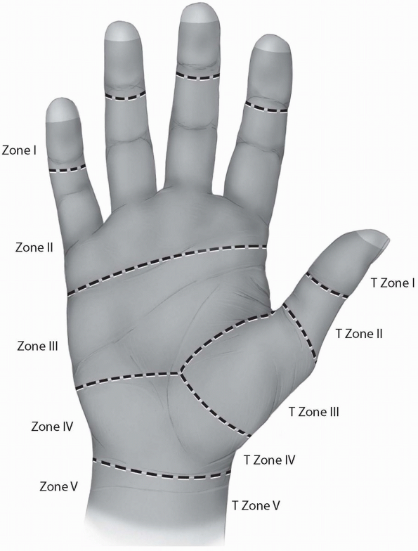
into five zones, I-V, based on their peculiar anatomy and their
prognosis after primary repair. Zone I represents the region distal to
the insertion of the FDS. Zone II describes the region where the FDS
and the FDP share the fibro-osseous sheath of the digit, from the level
of the metacarpal neck to the middle of the second phalanx. This zone
is also known as the “no man’s land,” a term introduced by Bunnell (4)
to describe the poor earlier results of flexor tendon repairs within
this area. Zone III represents the region between the distal part of
the transverse carpal ligament and Zone II. The tendons under the
transverse carpal ligament are located within Zone IV. Finally, Zone V
represents the most proximal part of the tendons within the region
proximal to the carpal canal in the forearm. A similar zone system has
been described for the thumb flexor tendon (Fig. 1-21).
the dorsal skin of the palm and the fingers. The volar skin is thicker
and tougher to stand wear, and more firmly attached to the underlying
structures. The palmar aponeurosis is a specialized thickening in the
deep fascia located under the palmar skin extending from the level of
the wrist joint to the level of the metacarpal heads. At that level, it
divides into longitudinal fibers which continue into the fingers. Both
the palmar aponeurosis and the longitudinal fibers give off superficial
attachments to the skin resulting in a rather nonmobile skin allowing
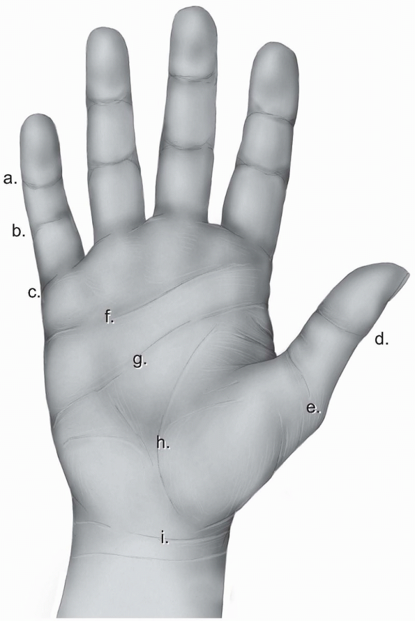
little plastic maneuvering. A system of creases, where the skin is
adherent to the deeper layers, allows for closing of the hand without
bunching up in folds.
identifies the distal end of the palm and is located over the proximal
third of the proximal phalanx. On the thumb, there is double flexion
crease over the interphalangeal joint called thumb interphalangeal crease and a wider double crease over the metacarpophalangeal joint called proximal thumb crease (Fig. 1-22).
begins at the midpoint of the hypothenar eminence and extends almost to
the radial end of the thenar crease. It signifies the level of the
metacarpal heads of the fingers. The distal palmar crease
is situated distal to the midpalmar crease and runs from the index
middle finger cleft to the ulnar border. It represents the level of
motion of the metacarpophalangeal joints of the ulnar three fingers. A
number of oblique and vertical skin creases of minor clinical
significance exist proximal to the midpalmar crease. Finally, the
distal forearm is separated from the palm with a transverse skin crease
called the wrist crease (Fig. 1-22).
 |
|
FIGURE 1-21 The five zones of the flexor tendons.
|
 |
|
FIGURE 1-22 The skin creases of the human hand. a, distal digital crease; b, proximal digital crease; c, palmar digital crease; d, thumb interphalangeal crease; e, proximal thumb crease; f, distal palmar crease; g, transverse or midpalmar crease; h, proximal palmar or thenar crease; i, wrist crease.
|
ability to firmly anchor a hand board or table on its side. Most hand
surgeries can be performed with the patient supine on the operating
table.
axillary, brachial, and peripheral nerve blocks can be used in the
majority of the surgical procedures of the hand. In case of
apprehensive adults or children, general anesthesia is usually
preferred. The final choice of the type of anesthesia for each
procedure is made by the anesthesiologist after being presented with
the patient’s and surgeon’s concerns and wishes.
emphasized the importance of atraumatic surgical technique in
reconstructive hand surgery. He mentioned: “A jeweler can’t repair a
watch in a bottle of ink and neither can we repair a hand in a pool of
blood” (4). A bloodless field achieved with a
tourniquet allows surgical dissection with accuracy and minimal trauma.
The tourniquet pressure should be at least 100 to 150 mm Hg higher than
the systolic blood pressure, reaching about 250 mm Hg in adults and 200
mm Hg in children. Wilgis (5) established that
the safe period of tourniquet inflation is about 2 hours since longer
use may lead to tourniquet palsy. In case there is a need for a longer
period than 2 hours, then the tourniquet should be deflated for 10 to
15 minutes and then reinflated.
glasses using small blades and instruments is essential in the
atraumatic technique advocated by Bunnell and other hand surgeons.
and the fingers. Certain basic principles should be followed at all
instances. The skin incisions should never be placed within deep skin
creases. The subcutaneous fat is very thin under these creases and
moisture tends to accumulate leading to maceration of the skin edges.
The incisions should be long enough to expose the underlying deep
structures without stretching the skin edges, since the mobility of the
volar skin in the hand is limited. The reflected skin edges should be
thick involving the underlying fat in order to avoid devascularization
of the skin edges. The direction of the dissection in the deeper
tissues can follow a different orientation than the direction of the
skin incision.
or angled incisions provide better exposure and are less noticeable
cosmetically. Furthermore, they can be extended with freer choice of
direction.
is perpendicular to the long axis of the skin creases. Therefore, an
incision should not cross a crease at or near a right angle since the
resulting scar being in the line of tension during early motion will
hypertrophy resulting in function impairment.
because necrosis or delayed healing can occur due to limited blood
supply of the bridged skin flap, especially if the incisions are too
close to each other or too long.
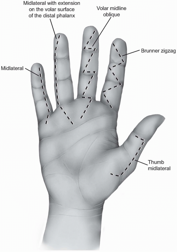
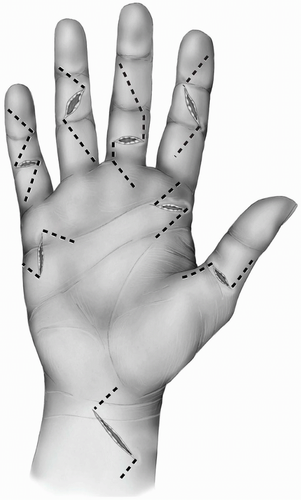
different finger incisions. The most popular are the zigzag incision
and the midlateral incision.
and consists of several oblique incisions between the different skin
creases meeting each other exactly over the creases. The angle between
the different creases should be about 90 degrees (Figs. 1-23 and 1-24A).
Angles of less than 90 degrees can lead to skin necrosis of the
corners. The apex of the angles is located at the edges of the creases
and should not extend more posteriorly since the neurovascular bundles
could be injured during mobilization of the skin flaps.
 |
|
FIGURE
1-23 The different finger skin incisions from right to left: Thumb midlateral incision, the Brunner zigzag incision, volar midline oblique incision, the midlateral incisionextending on the volar surface of the distal phalanx, and the midlateral incision. All the incisions have beenextended proximally within the palm. |
 |
|
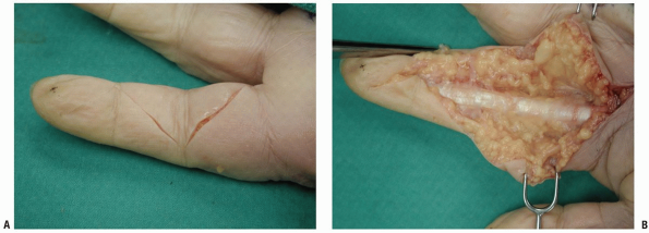
FIGURE 1-24 The volar zigzag finger incision described by Brunner. A: Superficial skin incision. B: Deeper dissection.
|
some underlying fat to avoid devascularizing the skin. Deeper surgical
dissection in a longitudinal fashion can be performed along the midline
where the fibrous-pulley system and the flexor tendons lie under the
subcutaneous fat. The dissection should be performed very carefully
along the lateral borders of the digit to avoid any injury to the
neurovascular bundles. The digital vessels and the nerve are located
beneath a thin fibrous layer called the Grayson’s ligament. Blunt
dissection in a longitudinal fashion can reveal the neurovascular
bundle, the most lateral borders of the fibrous-pulley system and the
bone (Fig. 1-24B).
oblique incision in which the whole skin incision is performed volarly,
along the midline of the finger (Fig. 1-23).
It is relatively safe and easily closed. The incision crosses the skin
creases transversely and slightly obliquely allowing exposure of the
flexor tendon sheath in the midline of the finger between the two
neurovascular bundles. Both zigzag incisions can be extended to the
palmar region using the same principles and following a zigzag pattern
to the distal palmar crease.
and the distal interphalangeal creases, which tend to extend slightly
more to the dorsal surface of the finger. These creases may disappear
in a swollen finger. Another important landmark is the junction between
the smooth volar skin and the dorsal wrinkled skin on the side of the
finger.
dorsolateral. A straight incision is performed connecting the more
dorsal points of the finger creases. The incision can reach up to the
lateral end of the fingernail distally and up to the web space
proximally. An alternative way to find the connecting points for the
skin incision is to flex the fingers and connect the most dorsal points
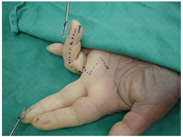
of the interphalangeal creases (Figs. 1-23 and 1-25).
This approach can be performed on radial or ulnar side of a finger but
never on both sides. The ulnar side of the index, middle, and ring
fingers and the radial side of the small finger are usually preferred,
since the incisions will not interfere with normal hand function
postoperatively.
of the incision. On the radial side of the index and middle fingers,
there is dorsal branch of the digital nerve that should be preserved
whenever it is encountered. The superficial skin dissection involves
dissection of the subcutaneous tissue and developing a volar skin flap.
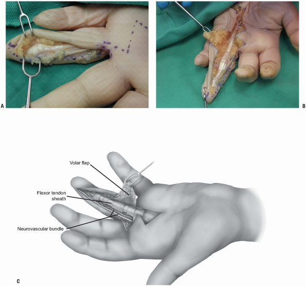
Deeper dissection should proceed carefully around the proximal
interphalangeal joint since the subcutaneous fat over the joint is
quite thin. Following the dissection of the fat, aim the dissection
volarward and expose the tendon sheath. A volar skin flap will develop
which contains the neurovascular bundle. The tendon sheath and the
flexor tendons can be exposed through this approach. Furthermore, the
opposite neurovascular bundle can also be exposed since its position is
anterolateral to the tendon sheath.
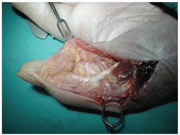
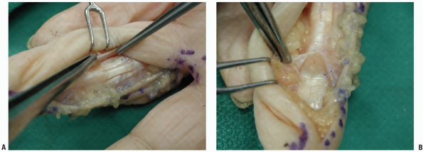
The same incision is performed from proximally up to the distal flexor
crease, but at that point the incision is curved obliquely into the
pulp of the finger. The neurovascular
bundle
should be exposed and protected through this incision. It can be best
found over the proximal interphalangeal joint. The dissection continues
volar to the neurovascular bundle and the flexor tendon sheath is
exposed. The advantage of this variation over the classical midlateral
approach is that it is easier to reach over the opposite neurovascular
bundle with less skin tension.
 |
|
FIGURE 1-25 The midlateral finger skin incision with extension in the palm.
|
 |
|
FIGURE 1-26 A-C:
Deeper dissection of the midlateral approach of the finger. The flexor tendon sheath has been approached raising a skin flap volar to the neurovascular bundle of the finger. |
proximally. Although both the digital nerve and artery are in danger,
an advantage of these approaches is that the incision is offset to the
flexor tendon sheath system providing an intact skin and subcutaneous
flap over it. On the contrary, the volar zigzag and volar midline
oblique incisions are relatively easier, since they do not require
mobilization of the neurovascular bundle, but the skin incision is
exactly over the tendon sheath system.
 |
|
FIGURE 1-27 The midlateral thumb skin incision.
|
similar to the finger incisions described previously. The midlateral
incision in the radial side is easier and can be extended by curving
its proximal end at the midmetacarpal area and creating a flap on the
palmar surface of the thumb (Figs. 1-23 and 1-27).
Care should be taken to avoid injury of the dorsal radial branch of the
superficial radial nerve which is located exactly under the skin. The
lateral surface of the thumb does not contain a lot of fat, especially
at the interphalangeal joint, so care should be taken to avoid incising
the joint or the volar plate.
incision. The two digital nerves at the level of the
metacarpophalangeal joint are very superficial on either side of the
flexor tendons and care should be taken to avoid injury of them.
of the tendon retracts, usually under the thenar eminence. It is
advisable not to extend the thumb incisions in the thenar eminence and
retrieve the tendon with an open approach through the thenar
musculature, but rather to retrieve the tendon through a separate
approach in the distal forearm and pass it under the thenar musculature
to the thumb.
be performed to access the flexor tendon at the level of the
metacarpophalangeal joint as well as the A1 pulley. The digital nerves
are located on either side of the tendon and should always be
identified and protected throughout the operative procedure.
 |
|
FIGURE 1-28 Incisions of the flexor tendon sheath. A: Ulnarly based flap of the sheath between the annular pulleys A2 and A4. B: Incision of the sheath distal to the annular A5 pulley.
|
sheath usually result in retraction of the proximal part of the tendon
within the sheath. In order to retrieve this part of the tendon and
perform the repair, the sheath should be incised at certain locations.
Various studies have revealed that the most important pulleys are the
annular A2 and A4. Therefore, the sheath must be opened away from these
pulleys, in the C1 pulley, in the C2 pulley, or in the C3-A5 pulley
complex (Fig. 1-28). If a wider exposure is needed, a radial- or ulnar-based flap of the sheath is created between the A2 and the A4 pulley (Fig. 1-28A).
In case that there is need to open the annular A2 or A4 pulleys, a Z
type of lengthening incision is preferred to enable repair of the
pulleys. Partial resection of the A2 or A4 should be avoided.
the skin and the skin creases apply to palmar incisions too. As a
general principle, the incisions in the palm tend to be more transverse
in the distal part and more longitudinal curving radially and parallel
to the closest skin crease in the proximal part. There is a great
variability of skin incisions in the palm, especially in the distal
part.
are the transverse incisions used in trigger fingers. The location of
these incisions is exactly over the midpalmar crease in most of the
patients, although they may be located slightly more distally in case
of the middle, ring, and small fingers. All these transverse incisions
can be extended more proximally towards the thenar crease keeping in
mind that the flexor tendon course is towards the midline from distal
to proximal as they exit from the carpal tunnel (Fig. 1-29).
 |
|
FIGURE 1-29 The different palmar skin incisions.
|
latter is dissected from the palmar fascia trying to preserve any
perforating small vessels that may supply the more superficial layers.
The palmar fascia is incised in any desired orientation keeping in mind
that the vital structures are under it. If wider exposure is desired,
part of the palmar fascia can be excised. The tendons and the
longitudinally oriented neurovascular bundles can be seen. It is
advisable to always locate the neurovascular bundles at this level and
protect them at all times during the flexor tendon surgical procedure.
under the palmar fascia in the proximal part of the palm. In the distal
palm, these structures are lying between the metacarpals heads and are
not protected by the palmar fascia. In the very distal part of the palm
the arteries and nerves are oriented longitudinally. In the proximal
part of the palm there are some structures with a transverse
orientation, like the superficial palmar arch and the thenar motor
branch of the median nerve.
of the transverse carpal ligament and will be discussed in conjunction
with the surgical approaches of the flexor tendons in the wrist.
involves release of the carpal tunnel and approach of the flexor
tendons in the proximal part of the palm and the distal forearm.
crease, the transverse skin crease of the wrist, and the tendon of
palmaris longus whenever it is present. The incision is placed just
ulnar to the thenar crease at the level of the Kaplan’s cardinal line,
curving radially proximally, remaining always on the ulnar side until
the level of the wrist crease. At that point, the incision is curved
ulnarly in order to avoid crossing the wrist crease transversely and
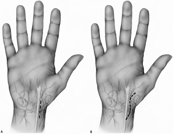
continues along the midline of the forearm (Fig. 1-30A).
 |
|
FIGURE 1-30 Surgical approach of the flexor tendons in the wrist with proximal midline extension in the forearm (A) and ulnar proximal forearm extension (B). The diagonal line represents the Kaplan’s cardinal line.
|
the skin flaps should be incised carefully. The palmar cutaneous branch
of the median nerve lies superficially between the flexor carpi
radialis and the median nerve and enters the palm in a variable course.
Dissection of the subcutaneous fat should be performed carefully,
trying to identify and protect branches of this nerve. After incision
of the subcutaneous fat, the tendon of the palmaris longus is visible
proximally and its insertion, the fibers of the palmar fascia, is
visible distally. The fibers of the palmar fascia should be incised
longitudinally along the line of the skin incision. The tendon of the
palmaris longus inserting in these fibers should be retracted ulnarly.
The median nerve is located under the tendon of the palmaris longus
between the palmaris longus and the tendon of the flexor carpi
radialis. The muscle fibers of the palmaris brevis muscle are located
under the palmar fascia and are incised longitudinally. The fibers of
the transverse carpal ligament are visible with their most proximal
part located at the level of the transverse wrist crease. A blunt
spatula-like instrument is placed between the median nerve and the
transverse carpal ligament. Careful incision of the fibers cutting on
the instrument to avoid any injury to the median nerve is performed. It
is advisable to transect the fibers on the ulnar side of the median
nerve to avoid injury to the motor branch to the thenar muscles. The
flexor tendons are visible around the median nerve within the carpal
tunnel and in the distal forearm. The tendons of the FDS, FDP, and FPL
are directly accessible along this incision. The flexor carpi radialis
and the FCU are located at the most ulnar and radial parts of the
incision at the level of the distal third of the forearm.
several dangers exist in this extended approach of the flexor tendons
in the wrist. The superficial palmar arch lies exactly over the tendons
at the exit of the carpal tunnel and proximal extension should be
performed cautiously. The motor branch of the median nerve usually
emerges from the radial part of the nerve either distal or under to the
transverse carpal ligament. There are few cases where the motor branch
arises within the carpal tunnel and pierces the transverse carpal
ligament posing a possible danger during the release of the carpal
tunnel. In the most proximal part of the incision, the ulnar nerve and
artery, the median nerve, and the radial artery are located between the
flexor tendons and should be protected during dissection.
the incision. Instead of a proximal midline extension in the distal
forearm, an ulnar longitudinal incision can be performed (Fig. 1-30B).
An advantage of this alternative approach is that the incision is not
performed exactly over the median nerve providing a well vascularized
skin flap over the nerve. A similar radial longitudinal incision should
be avoided because it places the palmar cutaneous branch of the median
nerve at risk.
common clinical situations. In these cases, the previously mentioned
surgical approaches have to be modified in order to incorporate the
skin lacerations. As a general principle, the skin laceration can be
extended proximally or distally using the Brunner zigzag approach (Fig. 1-31).
Adequate surgical exposure is needed to identify and expose the tendon
ends. Lacerated flexor tendons retract frequently in the palm unless
there is intact vinculum or lumbrical muscle preventing further
proximal retraction. The proximal end of the tendon may retract so much
that a wide exposure is needed. Another alternative is to perform an
independent proximal surgical exposure and retrieve the tendon at that
point and retract it to the more distal surgical approach under the
intact skin bridge. Such incisions can be performed in the palm at the
level of the distal palmar crease. In case of FPL laceration at the
base of the thumb, the proximal part of the tendon usually retracts
under the thenar musculature or even in the palm. An isolated radial
longitudinal incision may be necessary to retrieve the tendon in the
palm and retract it to the thumb.
necessarily immediately, to lessen the chance of a wound infection.
Whenever there is tendon, bone, or neurovascular structure exposed
immediate coverage is essential. Primary skin closure is preferable if
it can be achieved without tension; otherwise some type of skin
grafting is preferable.
 |
|
FIGURE 1-31 Incorporation of skin lacerations into the surgical approaches of the flexor tendons.
|
distal radius. While the most common is the dorsal approach, which
allows full exposure of the radiocarpal and midcarpal joints, the volar
approach for the treatment of fractures of the scaphoid (1, 2, 3, 4, 5, 6) and for internal fixation of distal radius fractures has had increasing clinical application and reported value (7, 8, 9).
common surgical approaches: (a) the volar radial approach for fractures
of the distal third and waist of the scaphoid and scaphoid nonunions
and (b) an extended volar radial forearm approach for the treatment of
distal radius fractures. These two surgical approaches will be
described.
approach is for the treatment of acute displaced fractures of the
scaphoid and for the treatment of scaphoid nonunions when there is a
volar flex or humpback deformity present (2,5,6,10, 11, 12, 13).
It has the potential for proximal extension to obtain bone graft from
the distal radius in the treatment of comminuted scaphoid fractures or
scaphoid
nonunions.
It has a further advantage of allowing correction of a volar angulation
deformity of a scaphoid fracture or scaphoid nonunion (10,14).
best managed by closed reduction and percutaneous screw fixation or by
open reduction and compression screw fixation (5,12,13,15, 16, 17). The volar radial approach extended from the scaphotrapezial joint distally to the distal radius proximally (see Figs. 1-32 and 1-33)
provides an excellent view to reduce the displaced scaphoid, bone graft
comminuted fractures, and insert a cannulated compression screw from a
distal to proximal direction across the fracture site.
nonunions with a humpback deformity. To provide adequate realignment of
the scaphoid and correction of carpal collapse associated with scaphoid
nonunion, interposition bone graft is often required (10,11,14). A volar radial approach (see Figs. 1-34 and 1-35)
allows for direct visualization of the nonunion site, mobilization of
the scaphoid fracture nonunion components, and insertion of a volar
radial bone graft to correct scaphoid nonunions and internal fixation
with compression screws.
plate can be placed on the tensile side of the radius and is protected
by overlying soft tissues (7, 8, 9,18, 19, 20, 21).
The volar approach for treatment of distal radius fractures is
basically an approach through the flexor carpi radialis subsheath. The
interval between the flexor carpi radialis and radial artery is
developed. Exposure of the entire distal radius or displaced
extra-articular and occasionally intra-articular fractures of the
distal radius can be achieved. This is a different approach than the
extended Henry approach in that the latter is lateral to the flexor
carpi radialis and includes a carpal tunnel exposure. The volar-radial
approach to a distal radius fracture can be combined with arthroscopic
reduction of intra-articular fractures of the distal radius or with
percutaneous pinning.
contraindicated for proximal pole scaphoid fractures where a dorsal
approach is preferred (6,17,22).
It is also contraindicated if there is a fracture dislocation of the
scaphoid wherein repair of dorsal ligaments is required along with
scaphoid fracture fixation through a dorsal surgical approach.
contraindicated when there is severe comminution of the distal radius
requiring open reduction and internal fixation of the joint articular
surfaces unless it is combined with a dorsal approach to the
radiocarpal joint or wrist arthroscopy (18,23, 24, 25). Precise anatomic alignment of the distal radius is required that cannot be achieved from a volar approach alone.
in particular, scaphoid nonunions, computerized tomography (CT) or
magnetic resonant imaging (MRI) is essential. MRI is preferred for
acute fractures with displacement and if one suspects vascular damage
to the scaphoid (avascular necrosis). CT (AP, lateral, axial) is
preferred to determine the degree of scaphoid angulation and
displacement and to measure the size of a potential interposition bone
graft (26, 27, 28).
traction posteroanterior and lateral radiographs provide the best
preoperative view of the extent of fracture displacement. Alternatively
one can use computed tomography (CT scans) (8,29).
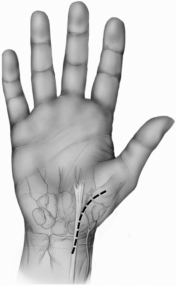
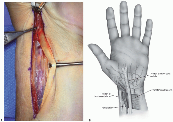
the scaphoid are to localize the radial styloid, the tuberosities of
the scaphoid and the trapezium, and the flexor carpi radialis tendon
and tendon sheath (Fig. 1-32).
-
Incision: a curvilinear incision or
straight incision is made along the volar radial aspect of the wrist
just over the tuberosity of the scaphoid if palpable and along the
flexor carpi radialis tendon sheath (Fig. 1-33). -
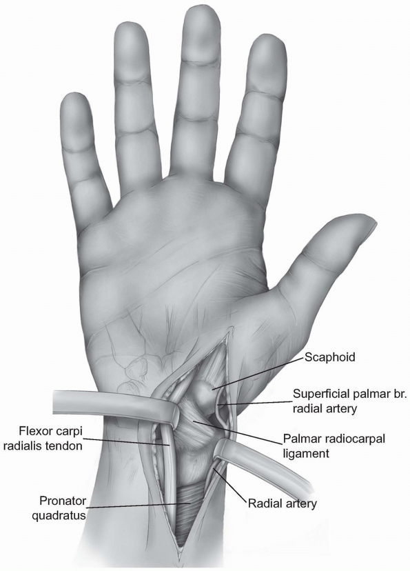
Careful dissection is performed to locate
branches of the lateral antebrachial cutaneous nerve and the volar
branch of the radial artery. The operative approach is then extended
proximally and distally
P.31
between the radial artery and the flexor carpi radialis tendon dissecting down to the capsule of the wrist (Fig. 1-34). -
The anatomic location for the wrist
capsule incision is between the radial collateral ligament and the
palmar radial scaphocapitate ligament (Fig. 1-35). -
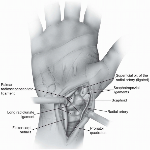
Occasionally, the incision needs to be
extended more ulnarly through the volar long radiolunate ligament. The
palmar (superficial) branch of the radial artery may need to be divided.-
Note: With traction of the thumb, the articulation between the distal radius and proximal pole of the scaphoid comes into view.
-
-
The volar carpal ligaments are reflected
from the waist and proximal pole of the scaphoid and the incision is
extended distally to the scaphotrapezial joint. With continued traction
on the wrist and thumb, one can assess the degree of displacement of an
acute scaphoid fracture as well as the amount of comminution present.
 |
|
FIGURE 1-32 Radial volar approach to scaphoid. A: Longitudinal incision between the flexor carpi radialis (FCR) and radial styloid and radial artery. B: Zigzag incision between radial styloid and flexor carpi radialis.
|
 |
|
FIGURE
1-33 Extended S-shaped exposure to the scaphoid; note radial artery, flexor carpi radialis tendon, trapezium tubercle, scaphoid, trapezoid. Surgical approach to scaphoid. |
 |
|
FIGURE
1-34 Extended palmar incision to distal scaphoid demonstrating deep palmar radiocarpal ligaments, palmar branch of the radial artery retracted radially or ligated; and distally, trapezium and the scaphotrapezial joint. |
-
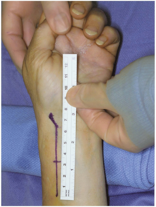
Incision: for the volar radial approach to the distal radius, the incision (curvilinear or straight) (Fig. 1-36)
is performed just radial to the flexor carpi radialis tendon and tendon
sheath. This is similar to the volar radial approach to the scaphoid.
The incision extends deep along the flexor carpi radialis tendon sheath
interval between the radial artery and flexor radialis from a distal to
proximal direction until the entire view of the distal radius fracture
comes about for inspection (8,9). -
The length of the incision should be 7 to 8 cm to provide for plate insertion.
-
The flexor carpi radial tendon is fully mobilized (Fig. 1-37).
-
The flexor carpi radialis is released from the subsheath and retracted radially.
-
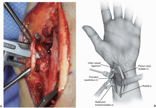
The brachioradialis muscle insertion is detached from the lateral (radial) aspect of the distal radius (Fig. 1-38) and divided. This reduces supinating force from the brachioradialis.
-
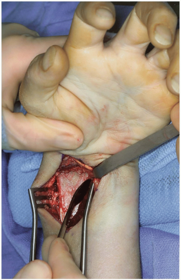
The pronator quadratus is released (Fig. 1-39) and reflected from the distal radius from a radial to ulnar direction with attached periosteum (Fig. 1-40).
-
With different forms of distraction
(finger traps or an occasional external fixator), alignment of the
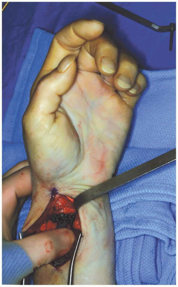
distal radius fracture is obtained and the plate is applied (Fig. 1-41). Percutaneous pins are inserted to hold the fracture in alignment. -
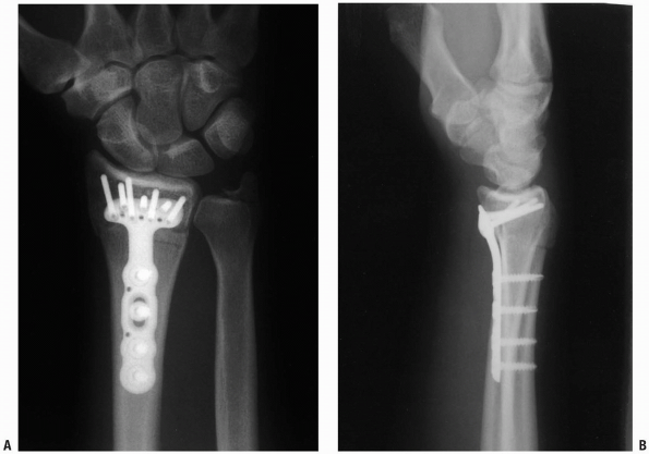
Appropriate x-rays are taken to ensure
that the fracture is adequately reduced and then one of a variety of
volar fixation plates is applied (Fig. 1-42).
 |
|
FIGURE
1-35 Exposure and division of radial volar carpal ligaments (palmar radioscaphocapitate and long radiolunate ligaments); divided and ligated superficial branch of radial artery. Inset: Divided volar radiocarpal ligaments (scaphoid fracture site). |
 |
|
FIGURE 1-36 Exposure core of distal radius fracture. Longitudinal incision 6 to 8 cm in length.
|
 |
|
FIGURE 1-37 A,B: Release and mobilization of flexor carpi radialis.
|
 |
|
FIGURE 1-38 Release and division of brachioradialis tendon.
|
-
It is important to extend the volar
radial approach distal enough to the scaphotrapezial joint and to
remove the lateral border of the trapezium if one is going to use a
Heune jig for compression of the scaphoid (6,10,14,30,31). -
A mini C-arm imaging of the wrist can
help to determine central position of a guidewire for cannulated screws
as well as proper placement of the proximal tip of the Heune jig
against the proximal pole of the scaphoid. -
Occasionally a radial styloidectomy may
be helpful to provide improved exposure of the scaphoid and to allow
ease of insertion of a volar radial interposition bone graft. -
To expedite volar capsular closure and
prevent late carpal instability, it is best to suture tag the radial
collateral and the radioscaphocapitate ligament and the long
radioscapholunate ligament and to carefully repair the volar wrist
capsule (3).
-
To allow for closure of the pronator
quadratus, it is important to incise the volar periosteum of the distal
radius as far radially as possible or to do a step cut detachment of
the pronator quadratus so that closure of the pronator over the volar
plate can be achieved (9). -
Often there are two main distal radius
fracture fragments when there is an intra-articular fracture of the
distal radius: the radial styloid component and the lunate fracture
component (7,23,32).
We recommend beginning ulnarly, reducing the lunate fossa fracture
components with intra-articular K-wire placed either dorsal to volar or
volar to dorsal, and then transfix the lunate fossa to the distal
radius. -
In wound closure, it is not necessary to
reattach the brachioradialis (deforming supinating force on the distal
radius). It is important as noted previously to reattach the pronator
quadratus and then allow the FCR subsheath to fall naturally back into
place and reapproximate, if possible, the deep and superficial fascia
of the forearm.
 |
|
FIGURE 1-39 A,B: Release of the radial border (insertion) of the pronator quadratus.
|
-
Avoid overcompression of the scaphoid.
-
Always leave a temporary K-wire in place before screw insertion to prevent rotational displacement of the scaphoid.
-
Remove the lateral portion of the
trapezium when using a Heune jig or K-wire to ensure central position
of any compression screw. -
Realign the lunate and proximal scaphoid (correcting any dorsal angulation) before fracture or nonunion reduction.
-
Avoid excessive lateral (radial) dissection with risk of injury to the scaphoid blood supply.
-
Tag and later repair the volar carpal ligaments.
-
Choose appropriate length internal fixation screws and then subtract back 2 mm.
 |
|
FIGURE 1-40 Reflection of pronator quadratus to expose the distal radius-volar surface.
|
 |
|
FIGURE 1-41 Plate application to the distal radius.
|
-
Obtain anatomic reduction with K-wires before plate fixation.
-
Use traction to assist with reduction (manual traction or external fixation).
-
Operate early (within the first 12 hours) or late (>36 hours) to avoid wound closure problems.
-
Consider step-cut lengthening the pronator quadratus to allow re-attachment during closure.
-
Consider reduction with external fixation for the very unstable, comminuted fractures.
-
Bone graft (autograft or allograft) for comminuted fractures, especially in the elderly.
 |
|
FIGURE 1-42 Posteroanterior (A) and lateral (B)
x-rays of the distal radius after plate fixation. Note lateral view position of screws proximal to the radiocarpal joint articular surface. |
most commonly employed in the setting of an acute proximal pole
scaphoid fracture; however, surgical exposure and internal fixation of
the scaphoid may also be indicated for (a) any displaced scaphoid
fracture; (b) scaphoid fractures with significant bone loss; (c)
fractures with angulation or rotation; or (d) scaphoid fractures
resulting in loss of the lateral intrascaphoid angle, fracture
dislocations of the scaphoid and greater arc injuries (1, 2, 3, 4, 5, 6, 7).
In addition, any scaphoid fracture which results in loss of carpal
alignment or which cannot be satisfactorily corrected or maintained by
manipulation and casting should be treated by operative reduction and
internal fixation (8).
approach. The palmar approach has been classically used for the
treatment of waist fractures and for the repair of nonunions (9).
A dorsal longitudinal approach to the wrist may also be used for
scaphoid exposure in cases of pan-carpal injury or in cases involving
concomitant distal radius fractures. When the scaphoid alone is
fractured one may utilize a dorsal radial exposure.
The dorsal radial approach to the scaphoid allows for exposure of the
proximal pole of the scaphoid, the dorsal mid waist, the
scapho-trapezial-trapezoid joint as well as the dorsal portion of
scapholunate interosseous ligament. The dorsal radial approach may be
used for cases of scaphoid non-union and allows for the utilization of
vascularized bone grafts from the dorsal distal radius (Fig. 1-43).
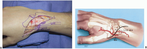
The dorsal radial exposure has the benefits of not violating the palmar
supporting ligaments of the wrist and preserves the palmar blood supply
to the scaphoid (1,10,11). The dorsal radial exposure may place the superficial branch of the radial nerve at risk (Fig. 1-44).
This approach provides only minimal exposure of the lunate and allows
for no visualization of the ulnar aspect of the wrist, because of this
the dorsal radial approach should not be used for the evaluation or
treatment of lesser or greater arc injury patterns, or in cases where
significant collapse is present within the scaphoid.
 |
|
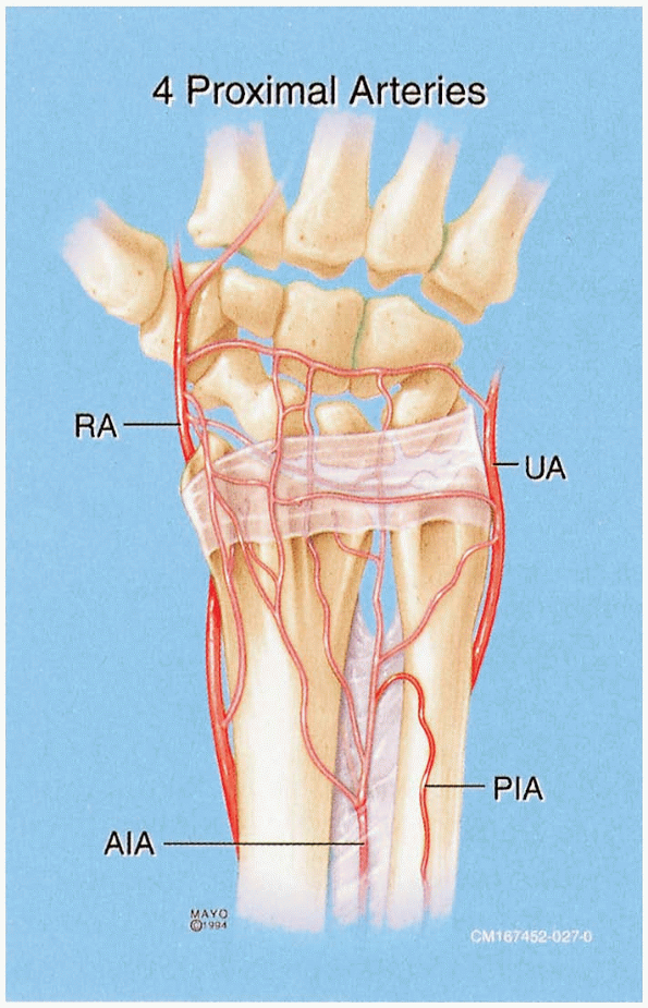
FIGURE
1-43 Arterial supply to the distal radius and scaphoid. The properly placed dorsal radial exposure protects the critical vascular supply to the scaphoid. |
 |
|
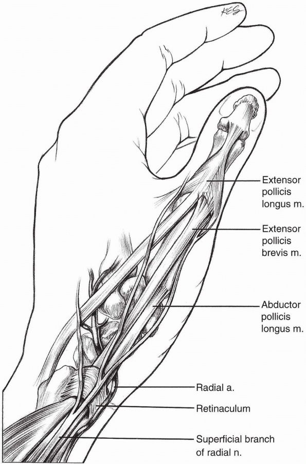
FIGURE
1-44 The superficial branch of the radial nerve although at risk can be avoided with the properly placed dorsal radial incision to expose the scaphoid. |
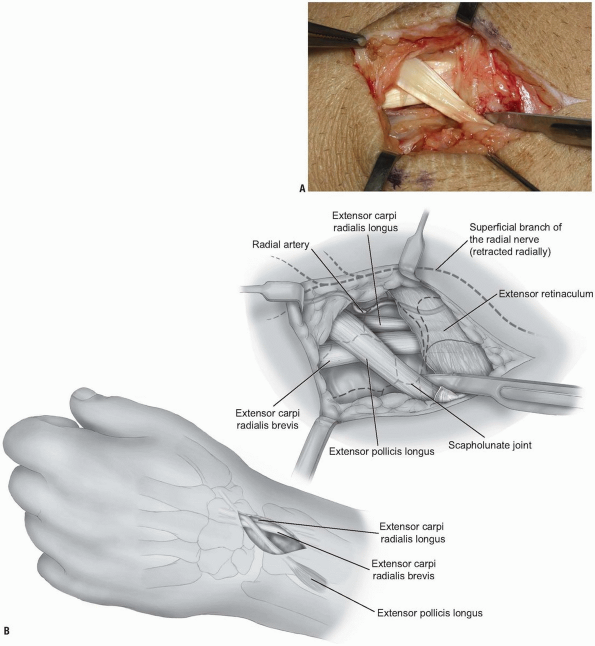
incision beginning over Lister’s tubercle and extending distally along
the line of extensor pollicis longus (EPL) (Fig. 1-45).
be used for scaphoid exposure in cases of pan-carpal injury or with
concomitant distal radius fractures and intercarpal or radiocarpal
arthrodesis. Subcutaneous dissection is carried out to identify the
branches of the radial nerve, passing over the 2nd compartment, which
are retracted radially.
If necessary the EPL may be released entirely from its compartment and
transposed radial to Lister’s tubercle to facilitate retraction.
Mobilization of the EPL also allows for identification of the posterior
interosseus
nerve running on the ulnar side of Lister’s tubercle which may be excised for partial wrist denervation.
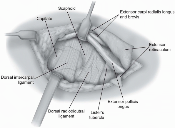
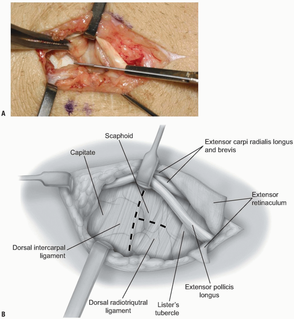
of the dorsal intercarpal ligament, with a straight axial cut, or a “T”
shaped incision (Fig. 1-48) (13).
-
Pearl: The
scapholunate joint is usually directly in line with Lister’s tubercle
and, the tubercle provides a useful anatomic landmark for the
initiation of the capsulotomy.
portion of the scapholunate ligament is inspected. Loose fragments of
articular cartilage, loose bodies, synovitis, and hemarthrosis may need
to be removed to improve visualization. The proximal pole may be
further evaluated by flexing and radially deviating the wrist.
-
Pearl: It
is important to remember that even in the presence of an acute scaphoid
fracture the scapholunate ligament may be injured and should be
examined for the possibility of instability or concomitant rupture.
 |
|
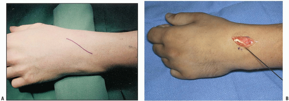
FIGURE 1-45 Standard skin incision used for the dorsal radial approach to the scaphoid (A). K-wire marks the position of the central scaphoid axis. The EPL can be seen in the base of the wound (B).
|
incision can be extended in a curvilinear fashion over the 1st dorsal
compartment (Fig. 1-49). The vascularized bone graft may then be harvested from the 1, 2 intercompartmental supra-retinacular vessels (ICSRA).
2 ICSRA and venae comitantes are visualized on the surface of the
retinaculum between the 1st and 2nd extensor tendon compartments (Fig. 1-50).
anastomosis with the radial artery (towards the anatomic snuff box).
The 1st and 2nd dorsal extensor compartments are opened at the level of
the bone graft site to create a cuff of retinaculum containing the
vessels and their nutrient arteries to bone.
dorsal-radial capsulotomy is made to expose the scaphoid non-union site
and create the trough at the non-union site (Fig. 1-51).
-
Pearl: With
the thumb held in 45 degrees of palmar and radial abduction the EPL
tends to follow the long axis of the scaphoid. If there is an
uncertainty about fracture location, K-wires may be placed into the
scaphoid, prior to capsulotomy, to verify position prior to creating
the dorsal capsulotomy.
 |
|
FIGURE 1-46 A,B:
The EPL is mobilized by releasing the distal portion of the 3rd compartment retinaculum. This maneuver facilitates retraction of the EPL. |
 |
|
FIGURE
1-47 The dorsal radial capsule is exposed by retracting the extensor carpi radialis longus brevis and the extensor pollicis longus radially. In some instances the extensor pollicis longus will need to be released from its compartment in order to provide adequate visualization. |
 |
|
FIGURE 1-48 A,B:
With the EPL and 2nd compartment tendons retracted radially the dorsal wrist capsule is opened through a short vertical incision. |
 |
|
FIGURE 1-49 A,B:
A modification of dorsal radial incision is made to increase exposure in cases requiring a vascularized graft from the dorsal distal radius. The incision is carried in a lazy S fashion over the first dorsal compartment to allow for exposure of the 1, 2 ICSRA vessels. |
 |
|
FIGURE 1-50 Identification of the 1, 2 ICSRA vessels, seen at tip of probe.
|
 |
|
FIGURE
1-51 A transverse capsulotomy has been made in the dorsal wrist capsule. In cases of vascularized grafting from the 1st and 2nd compartment, the 2nd and 3rd compartment tendons are retracted ulnarly to allow for mobilization and placement of the vascularized graft. Here a trough has been created in the scaphoid at the non-union site to accept the vascularized graft. |
few and may include injury to the radial sensory nerve branch, tendon
injury to the 2nd or 3rd compartment tendons, and post-operative
extensor tendon adhesions. Hypertrophic scarring and wound infection
may also occur. The dorsal radial exposure is not ideal for
scapholunate or perilunate fracture dislocations, where exposure of the
lunate is important for adequate reduction. In addition, this exposure
limits access to the dorsal capsule if formal dorsal capsulodesis is to
be performed for cases of static scapholunate instability. Also this
approach may be inadequate for restoring scaphoid height in cases of
scaphoid malunion or nonunions exhibiting significant humpback
deformity. In such cases we have found that the volar approach allows
for easier cortical graft placement and facilitates correction of
scaphoid alignment.
risk with the dorsal radial approach and one must be wary not to injury
the vessels entering at the radial dorsal crest during fracture
exposure. Overall, however, the dorsal radial approach provides ample
and easy access to the scaphoid for most cases of acute fracture and
non-union.
A, Ebraheim NA, Lu J, et al. A modified dorsal approach to the wrist
for arthrodesis of the nonrheumatoid wrist. An anatomical study. J Hand Surg 1996:21B:434-436.
AL, Seif SS. Anatomic dissections relating the posterior interosseous
nerve to the carpus, and the etiology of dorsal wrist ganglion pain. J Hand Surg 1978;3A:326-332.
SE, Dellon AL. The overlap pattern of the lateral antebrachial
cutaneous nerve and the superficial branch of the radial nerve. J Hand Surg 1985;10A: 522-526.
F. Note sur une disposition anatomique propre à la face antérieure de
la région du poignet et non encore décrite par le docteur. Bull Soc Anat Paris 1861;6:184-186.
JT, Watumull D. Anatomic study of the ulnar nerve and related vascular
anatomy at Guyon’s canal: A practical classification. J Hand Surg 1996;21A:626-633.
JR, Blythe W. The finger flexor tendon sheath and pulleys: Anatomy and
reconstruction. In: AAOS Symposium on Tendon Surgery in the Hand. St.
Louis: CV Mosby, 1975:81-87.
HE, Verdan CE. Report of the Committee on Tendon Injuries
(International Federation of Societies for Surgery of the Hand). J Hand Surg 1983;8A:794-798.
M, Vall A, Salo JM, et al. Carpal alignment after different surgical
approaches to the scaphoid: A comparative study. J Hand Surg 1988;13A:604-612.
TE, Gilbert M, Murray LW, et al. Displaced scaphoid fractures treated
with open reduction and internal fixation with a cannulated screw. J Bone Joint Surg 2000;82A(5):633-641.
RS, Bennett JD, Roth JH, et al. Arthroscopic diagnosis of
intra-articular soft tissue injuries associated with distal radius
fractures. J Hand Surg 1997;22A:772-776.
T, Horodyski M, Smith DW. Functional outcomes of unstable distal radius
fractures: ORIF with a volar plate versus external fixation. J Hand Surg 2005;30A(2):89-99.
KW, McAdams TR. Central screw placement in percutaneous screw scaphoid
fixation: A cadaveric comparison of proximal and distal techniques. J Hand Surg 2004;29A(1):74-79.
KA, Larabee L, Arnoczky SP, et al. Anatomic placement of the
Herbert-Whipple screw in scaphoid fractures: A cadaver study. J Hand Surg 2001;26A(5):883-892.
MD, Fischer MD. Treatment of unstable distal radius fractures: Methods
and comparison of external distraction and ORIF versus external
distraction-ORIF neutralization. J Hand Surg 1997;22A:238-251.
SF, Bean JW, Schram RA. Transcaphoid fracture dislocations treated with
open reduction and Herbert screw internal fixation. J Hand Surg 1987;12:992-999.
M, Vall A, Salo JM, et al. Carpal alignment after different surgical
approaches to the scaphoid: A comparative study. J Hand Surg 1988;13A:604-612.