
presents a challenge to orthopaedic surgeons. First, these fractures
are “osteoporotic” fractures that by definition represent metaphyseal
fractures that occur primarily in women older than the age of 50. This
results in compromised bone quality, which limits the potential to
achieve secure internal fixation. Second, the muscular attachments of
the proximal humerus and the associated deforming forces make it
difficult to obtain and maintain an acceptable closed reduction. Third,
the radiographic evaluation of the fractures can also be challenging
because of the displacement patterns and the overlapping bony
structures. Fourth, fractures that result in displacement of the
articular segment and the tuberosities are at significant risk for the
development of osteonecrosis. Therefore, hemiarthroplasty has become an
important treatment option for complex proximal humerus fractures in
the elderly. This chapter illustrates hemiarthroplasty of the proximal
humerus.
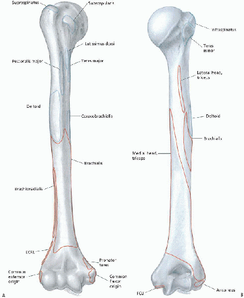
The anatomic neck is the junction between the humeral head and the
tuberosities. The surgical neck lies between the tuberosities and the
shaft. The rotator cuff is composed of four muscular divisions: (a) the
subscapularis, which inserts on the lesser tuberosity and acts as an
internal rotator of the glenohumeral joint; (b) the supraspinatus
tendon, which inserts on the greater tuberosity and acts to depress the
humeral head into the glenoid during elevation of the arm; (c) the
teres minor, and (d) infraspinatus muscles, which are the external
rotators of the shoulder and also insert on the greater tuberosity (Fig. 6-1).
The biceps tendon, which lies in the anteriorly directed bicipital
groove, provides a useful anatomic landmark for judging rotational
deformity of the humeral head during operative management (see Fig. 3-2).
This system is based on the anatomic relationship of the four major
anatomic segments: the humeral head, greater tuberosity, lesser
tuberosity, and the proximal humeral shaft beginning at the level of
the surgical neck. Fracture types are based on the presence of
displacement of one or more of the four segments. For a segment to be
considered displaced, it must be either greater than 1 cm displaced or
angulated more than 45 degrees from its anatomic position.
four-part fractures. A two-part fracture is characterized by
displacement of one of the four segments, with the remaining three
segments either not fractured or not fulfilling the criteria for
displacement. Four types of two-part fractures can be encountered
(greater tuberosity, lesser tuberosity, anatomic neck, and surgical
neck). A three-part fracture is characterized by displacement of two of
the segments from the remaining two nondisplaced segments. Two types of
three-part fracture patterns are encountered. The more common pattern
is characterized by displacement of the greater tuberosity and the
shaft from the lesser tuberosity, which remains with the articular
segment. The much less commonly encountered pattern is characterized by
displacement of the lesser tuberosity and shaft from the greater
tuberosity, which remains with the articular segment. A four-part
fracture is characterized by displacement of all four segments.
displaced proximal humeral fractures associated with either anterior or
posterior dislocation of the humeral head. Six types of
fracture-dislocation patterns can occur. In addition, Neer described
articular surface fractures: impression fractures and head-splitting
fractures. Impression fractures of the articular surface most often
occur in association with chronic dislocations. Head-splitting
fractures are usually associated with other displaced fractures of the
proximal humerus in which the disruption or “splitting” of the
articular surface is the most significant component.
proximal humeral fractures include (a) four-part fractures and
fracture-dislocations, (b) three-part fractures and
fracture-dislocations in elderly patients with osteopenic bone, (c)
head-splitting fractures, (d) anatomic neck fractures that
cannot
be adequately reduced and internally fixed, and (e) chronic anterior or
posterior humeral head dislocations with impression fractures that
involve more than 40% of the articular surface.
 |
|
FIGURE 6-1. Right humerus. A: Anterior aspect, showing muscle origins and insertions. B: Posterior aspect, showing muscle origins (red) and insertions (blue). (From Botte MJ. Muscle anatomy. In: Doyle JR, Botte MJ, eds. Surgical anatomy of the hand and upper extremity. Philadelphia: Lippincott Williams & Wilkins, 2003:92-184, with permission.)
|
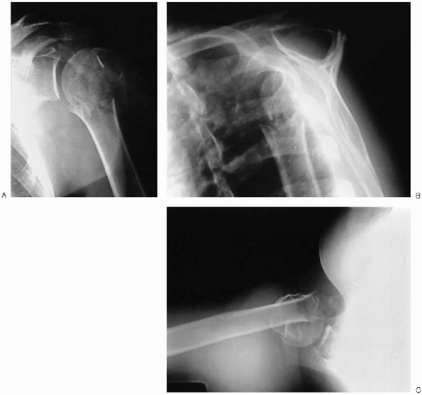
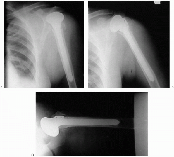
(AP) and lateral views of the shoulder obtained in the plane of the
scapula and an axillary view (Fig. 6-2). The
scapular AP view offers a general overview of the fracture and is
usually evaluated first. The scapular lateral assists in delineating
the position of the humeral head relative to the glenoid and is
particularly useful in showing dislocations or posteriorly displaced
fragments. The axillary view also permits assessment of the
glenohumeral relationship.
 |
|
FIGURE 6-2. Anteroposterior (A), Y view (B), and axillary (C) revealing a displaced proximal humerus fracture.
|
to perform preoperative templating to determine the approximate humeral
and head size. Using templates, magnified to account for radiographic
magnification, a stem of appropriate size is chosen. For cemented
insertion, adequate space must be maintained around the stem to
accommodate the cement mantle (usually 2 mm).
 |
|
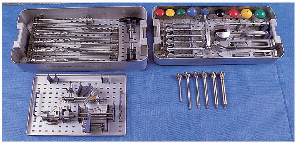
FIGURE 6-3. The equipment needed for hemiarthroplasty of the shoulder. Hemiarthroplasty set for humerus: reamer set (top left tray), accessory instruments (bottom left tray), trials (top right tray), trials (bottom right).
|
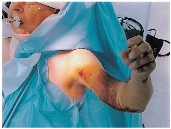
position. The head of the operating table is elevated approximately 30
degrees in a modified beach chair position (Fig. 6-4).
A small bolster is placed behind the involved shoulder. The patient is
moved off to the side of the table so that the upper extremity can be
placed into maximum extension without obstruction by the operating
table. The patient is secured to the operating table to minimize any changes in position intraoperatively. The entire upper extremity is prepped and draped to allow full mobility during the procedure.
 |
|
FIGURE 6-4.
The patient is placed on the operating table in a supine position. The head of the operating table is elevated approximately 30 degrees in a modified beach chair position. |
 |
|
FIGURE 6-5.
A straight deltopectoral incision is used that begins just lateral to the tip of the coracoid process and extends distally and laterally to the insertion of the deltoid. |
straight deltopectoral incision is used that begins just lateral to the
tip of the coracoid process and extends distally and laterally to the
insertion of the deltoid (Fig. 6-5).

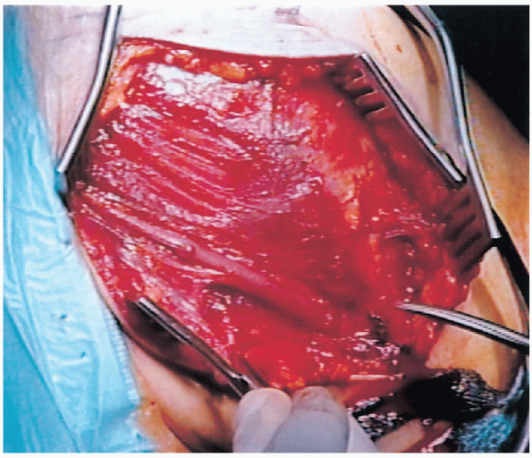
The subcutaneous tissues are divided and medial and lateral flaps
elevated to expose the deeper muscular layers. The deltopectoral
interval is identified by localization of the cephalic vein (Fig. 6-6).
The cephalic vein is usually retracted laterally with the deltoid
muscle. In some instances, the cephalic vein is more easily retracted
medially with the pectoralis major. In either case, care should be
taken to preserve the cephalic vein throughout the procedure.
 |
|
FIGURE 6-6. The deltopectoral interval is identified by localization of the cephalic vein.
|
 |
|
FIGURE 6-7. Retraction of the conjoined tendon and the pectoralis major medially and the deltoid laterally.
|
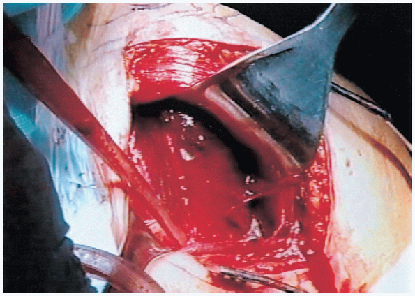
major. The conjoined tendon muscles are identified and the
clavipectoral fascia is divided at the medial edge of the conjoined
tendon muscles. The conjoined tendon muscles and the pectoralis major
are retracted medially and the deltoid is retracted laterally (Fig. 6-7).
This can be most easily accomplished with the use of a self-retraining
type retractor. By evacuating the fracture hematoma, the deeper
structures can be visualized.
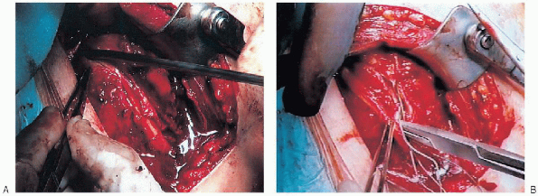
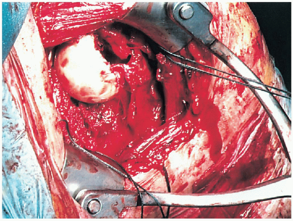
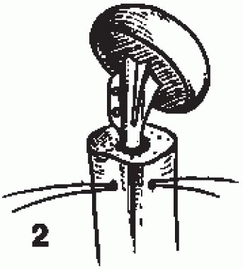
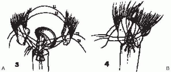
The biceps tendon provides an orientation to the greater and lesser
tuberosities. The lesser tuberosity is located medial to the biceps
tendon and the greater tuberosity is located superiorly and laterally.
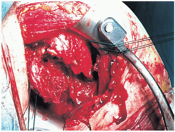
Each tuberosity is tagged with a heavy suture for easier mobilization (Fig. 6-9).
These sutures are placed at the tendon insertion site because this is generally the most secure area. Placement of the sutures through the tuberosity itself can result in fragmentation.The lesser tuberosity is mobilized and retracted medially while the
greater tuberosity is retracted laterally and superiorly. This allows
visualization of the articular segment. In four-part fractures this
segment is generally devoid of soft tissue attachments and is easily
removed (Fig. 6-10).
 |
|
FIGURE 6-8. The biceps tendon is identified (A) and tagged with a suture (B).
|
 |
|
FIGURE 6-9. Each tuberosity is tagged with a heavy suture for easier mobilization.
|
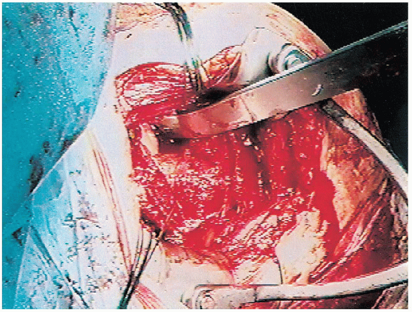
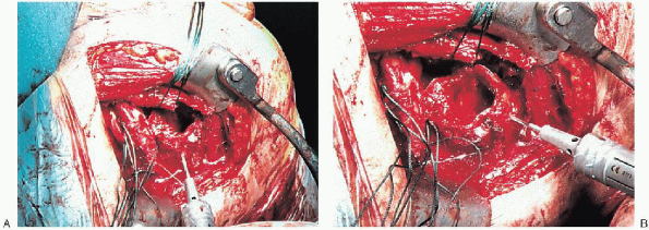
humerus is placed in extension to expose the proximal portion of the humeral shaft (Fig. 6-12). A series of intramedullary reamers are used to prepare the canal (Fig. 6-13). Reaming is continued until there is cortical contact. At this point a trial component of appropriate size is inserted (Fig. 6-14). Because
of proximal bone loss secondary to fracture, it is necessary to place
the prosthesis in a “proud” position. However, it is usually difficult
to maintain the prosthesis in this position and to control rotation
during trial reductions. To overcome this problem, a surgical sponge is
wrapped around the prosthesis. This fills the canal and maintains the
prosthesis in proper position. The desired position of
retroversion is 20 to 35 degrees. This can be modified if there is a
preexisting chronic dislocation or fracture-dislocation. The position
of retroversion is confirmed by comparing the position of the
prosthesis with the transepicondylar axis. In addition, the position of
the lateral or anterior flange of the prosthesis in relation to the
adjacent humeral cortex is marked and used to confirm proper position
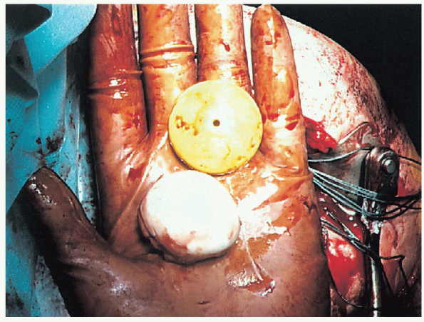
during cementing. The choice of head size is based upon the size of the
removed humeral head regardless of whether modular or nonmodular
systems are used (Fig. 6-15). With the implant in place the trial reduction is then performed.
 |
|
FIGURE 6-10. Visualization and removal of the articular segment.
|
 |
|
FIGURE 6-11. Inspection of the glenoid articular surface.
|
 |
|
FIGURE 6-12. The humerus is placed in extension to expose the proximal portion of the humeral shaft.
|
the humeral head is reduced onto the glenoid, the greater and lesser
tuberosities are pulled into position. The biceps tendon is allowed to
fall between the tuberosities. Traction on the
tuberosity sutures not only maintains the tuberosities in position but
also provides a more realistic assessment of stability.
Assessment of posterior, inferior, and anterior stability is assessed
by translating the humeral head as follows: up to 50 % of posterior
translation of the humeral head on the glenoid is acceptable as is 50%
of inferior translation.
However, anterior translation should not exceed 25%. If these
parameters are exceeded, the position of the component is reevaluated
to confirm
that
it has not subsided or rotated in the canal. If soft tissue laxity is
excessive, a larger humeral head is used. Conversely, if soft tissue
tension is excessive a smaller humeral head may be necessary. In either
situation, repeat assessment of stability is required to confirm that
the proper components and position have been chosen. When the proper
position and component size is confirmed, the trial prosthesis is
removed.
 |
|
FIGURE 6-13. Reaming of the humeral canal.
|
 |
|
FIGURE 6-14.
At this point a trial component of appropriate size is inserted. Because of proximal bone loss secondary to fracture, it is necessary to place the prosthesis in a proud position (A). To help maintain the prosthesis in this position and to control rotation during trial reduction, a surgical sponge is wrapped around the prosthesis (B). |
 |
|
FIGURE 6-15. Comparison of the removed humeral head to the trial humeral head.
|
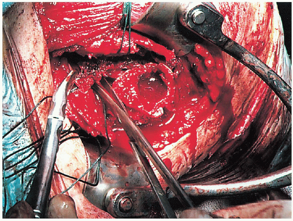
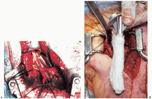
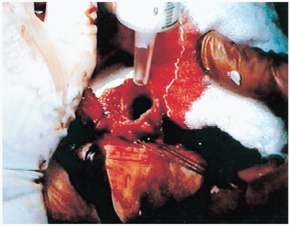
These holes are placed approximately 1.5 to 2 cm distal to the level of
the surgical neck component in proximity to the bicipital groove. Two
heavy nonabsorbable sutures are passed through one drill hole into the
medullary canal and then exit through the second drill hole (Fig. 6-17).
These sutures are used for tuberosity fixation. The medullary canal is
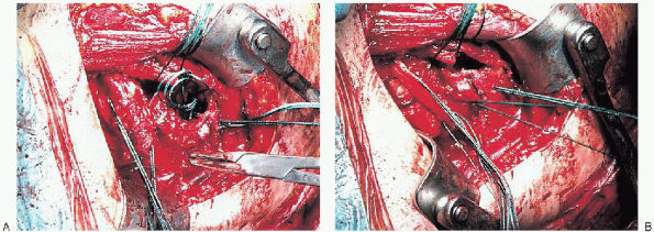
irrigated copiously and any loose cancellous bone removed. The use of
the cement restrictor is based on personal preference. We generally use
a cement restrictor to enhance cement distribution (Fig. 6-18).
However, we avoid any formal pressurization of the cement to decrease
the possibility of humeral shaft fracture. The canal is packed with a
sponge to obtain adequate drying before cementing.
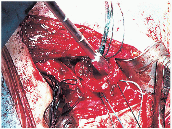
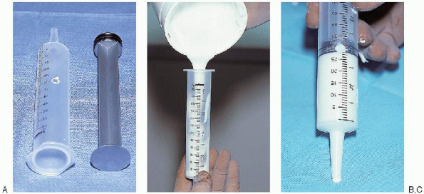
syringe is vented by preparing a hole at the 20- to 30-cc level. This
allows air to escape during insertion of the plunger so that a
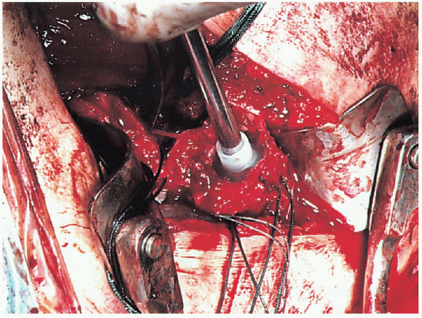
continuous column of cement is formed. The cement is then injected into the canal (Fig. 6-20).
During insertion of the prosthesis it is essential to maintain the
prosthesis in the proper proud position as well as in the desired
position of retroversion.
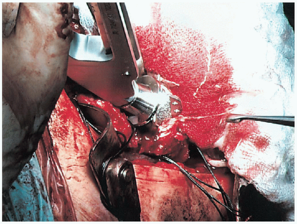
The prosthesis is held in position until the cement is completely set
to avoid inadvertent subsidence or rotation into an unacceptable
position (Fig. 6-21). When the cementing
is complete, the position is confirmed. When a modular component is
being used, the modular head is impacted into place making certain that
the taper is dry and free of any debris.
 |
|
FIGURE 6-16.
Two drill holes are placed through the humeral cortex into the medullary canal. These holes are placed approximately 1.5 to 2 cm distal to the level of the surgical neck component in proximity to the bicipital groove. |
 |
|
FIGURE 6-17.
Two heavy nonabsorbable sutures are passed through one drill hole into the medullary canal and then exit through the second drill hole. |
 |
|
FIGURE 6-18. Placement of the cement restrictor.
|
 |
|
FIGURE 6-19. The cement is mixed and poured into a vented 50-cc Toomey-type syringe (A) approximately 1 minute after mixing (B). This syringe is vented by preparing a hole at the 20- to 30-cc level (C).
|
shaft is a critical component of this procedure. Proper reattachment
and secure fixation enhances the probability of a successful outcome in
terms of range of motion and overall function. However, careful
attention must be given to the technical aspects of this portion of the
procedure. Heavy nonabsorbable sutures are used. These sutures are
generally passed through the rotator cuff tendons just at their
insertion into the tuberosities. The biceps tendon is allowed to fall
between the tuberosities and is incorporated into the fixation. This
results in a “functional tenodesis” but probably preserves at least a
portion of its humeral head depressor function.
 |
|
FIGURE 6-20. Injection of the cement into the humeral canal.
|
placement of longitudinal sutures to bring the tuberosities into a
position below the prosthetic articular surface and into contact with
the humeral shaft and (b) transverse suture fixation, which brings the
tuberosities into contact with each other and maintains the
tuberosities in the distal position obtained with the longitudinal
sutures. This is analogous to the principles of fixation of the greater
trochanter in hip surgery in which longitudinal wires are used to
advance the trochanter distally into the proper position and transverse
wires are used to secure the trochanter in this position.
(Fig. 6-22).
The first longitudinal suture is placed in a figure-of-eight fashion
through the supraspinatus tendon as it inserts into the greater
tuberosity and then through the upper portion of the subscapularis
tendon as it inserts into the lesser tuberosity. The second
longitudinal suture is passed in similar fashion through the
infraspinatus tendon as it inserts into the greater tuberosity and
through the lower portion of the subscapularis tendon as it inserts
into the lesser tuberosity. These sutures are passed but not tied.
 |
|
FIGURE 6-21.
The prosthesis is held in position until the cement is completely set to avoid inadvertent subsidence or rotation into an unacceptable position. |
 |
|
FIGURE 6-22. Placement of the sutures through the humeral shaft to reattach the tuberosities. (See text for details.)
|
supraspinatus tendon as it inserts into the greater tuberosity, through
the upper hole of the lateral keel of the prosthesis and then through
the upper portion of the subscapularis tendon as it inserts into the
lesser tuberosity (Fig. 6-23). The second
transverse suture is passed, in similar fashion, through the
infraspinatus tendon, through the lower hole in the lateral keel, and
through the lower portion of the subscapularis tendon. The
suture tying sequence is important. The first longitudinal suture
should be tied first. This will advance the tuberosities distally below
the articular surface of the prosthesis and into contact with the
humeral cortex, which is essential to obtain bone-to-bone healing. The
second longitudinal suture is then tied for enhanced fixation. When the
tuberosities are confirmed to be in proper position the superior
transverse suture is tied followed by the inferior transverse suture.
Transverse fixation brings the tuberosities into contact with each
other and maintains the position obtained by the longitudinal sutures.
Tuberosity reattachment is performed with the arm in approximately 20
degrees of abduction, neutral flexion, and 10- to 20-degrees external
rotation. When the tuberosity fixation is completed, the stability of
the fixation is carefully assessed. Range of motion in forward
elevation, external rotation, internal rotation, and abduction is
performed to determine the specific limits of motion that will be
allowed in the postoperative rehabilitation program. In
addition, we have found that bone grafting the tuberosities can enhance
the healing potential. Cancellous bone from the humeral head is placed
in the area of contact between the shaft and the tuberosities and
between the tuberosities.
 |
|
FIGURE 6-23. Schematic showing method of reattachment of tuberosities (A and B). (See text for details.)
|
nonabsorbable sutures. This is performed with the humerus in external
rotation to decrease the possibility that rotator interval closure will
restrict rotation. A closed suction drain is usually placed deep to the
deltopectoral interval and brought out through the skin distally and
laterally. The deltopectoral interval is repaired with absorbable
suture as is the subcutaneous tissue. This skin closure is performed
with either sutures or staples. A sterile dressing is applied and the
upper extremity is placed in a sling.
This includes an AP view of the shoulder with the humerus in internal
rotation (on the chest) and maximum external rotation as defined by the
intraoperative assessment. An axillary view is also obtained. These
radiographs provide excellent visualization of the position of the
prosthesis and the position of the tuberosities.
 |
|
FIGURE 6-24. Postoperative anteroposterior view of the shoulder with the humerus in internal rotation (A), external rotation (B), and an axillary view (C).
|
on a rehabilitation program that consists of active range of motion of
the elbow, wrist, and hand and passive range of motion of the shoulder.
External rotation is limited based on the intraoperative evaluation.
This is important to avoid any excess stress on the tuberosity repair
that could compromise healing. Internal rotation is allowed to the
chest. These exercises are continued for the first 6 to 8 weeks.
Radiographs are obtained approximately 2 weeks following surgery to
confirm the position of the tuberosities. Additional radiographs are
obtained at 6 to 8 weeks following surgery to assess the degree of
tuberosity healing. If tuberosity healing is sufficient, the sling is
discontinued and an active range-ofmotion program is begun. The patient
is encouraged to use the involved upper extremity for activities of
daily living. Passive range of motion is continued with gentle
stretching to increase the overall range. At 8 weeks following surgery,
isometric deltoid and internal and external rotator strengthening
exercises are begun. Vigorous strengthening exercises are not begun
until active forward elevation of at least 90 degrees is obtained. Our
experience has shown that patients can expect continued recovery during
the first year following surgery, although most recovery will occur
during the first 6 months.