
meaning “straight”) have played an integral role in the management of
spinal pathology for thousands of years. Smith, in his 1908 article,
“The Most Ancient Splints,” described brace use in ancient Egypt more
than 2500 years ago. Much of the early literature focused on treatment
of spinal deformities, including Pare’s metal jacket, popular in the
late 16th century, and Andre’s iron cross cervical brace, featured in
the early 18th century. Today, spinal bracing continues to be a
mainstay of treating deformity and acute and chronic spinal injuries.
external devices applied to restrict motion in a particular segment. As
such, they can be categorized broadly based on the region they are
employed to immobilize, as follows:
-
Cervical orthoses
-
Cervicothoracic orthoses (CTOs)
-
Thoracolumbosacral orthoses (TLSOs)
-
Lumbosacral orthoses (LSOs)
-
Sacroiliac orthoses
studies, and clinical utility of commonly used, commercially available
spinal orthoses.
a result of better understanding of spinal biomechanics. Conceptually
the spine can be thought of as a series of semirigid segments
interconnected by viscoelastic linkages. Spinal kinematics involves
motion in 6 degrees of freedom, with rotation about three axes and
translation along the three coordinates. For clinical considerations,
testing (particularly involving normal subjects) generally has been
confined to three planes of motion:
-
Flexion/extension
-
Axial rotation
-
Lateral bending
be evaluated by a variety of methods. Standard radiography, typically
using flexion/extension views, has been employed. Cineradiography
evaluates motion using fluoroscopy with movie film. Goniometry uses
external devices attached to the subject to measure spinal motion.
Goniometry has been shown to correlate fairly well with radiographic
techniques and avoids exposing subjects to radiation. This advantage is
offset, however, by some decreased accuracy and lack of information on
motion at any particular segment.
spine through the application of external forces, orthotic design must
account for regional variations of the surrounding anatomy. These
variations include the vital soft tissue structures of the anterior
neck, the rigid thoracic ribcage, and the bony pelvis at the base of
the lumbar spine. The surrounding soft tissue envelope has a
substantial effect on the ability of an externally applied force to
control spinal movement. Pressure measurements on the soft tissues may
be an objective way to assess the fit of a spinal orthosis. The role of
soft tissue pressure measurement as an index of applied corrective
force for the deformity bracing is unclear. The intervening soft tissue
envelope is also an area of potential complication with problems
ranging from skin breakdown, local pain, decreased vital capacity, and
increased lower extremity venous pressure.
spinal bracing, improvements in the materials available for brace
manufacture have led to dramatic advancements in design. During the
18th century, braces generally were constructed of leather, iron, and
wood. German developments in the 19th and early 20th centuries led to
many new brace designs, with paper cellulose and glue being added to
wooden or iron frames. Newer composite materials, polymer resins, and
thermoplastics have led to a proliferation of commercially available
orthoses that are lightweight and comfortable without sacrificing the
stability afforded by the heavier, more cumbersome designs of the past.
Commonly used materials in the fabrication of orthoses are listed in Table 32-1.
into cervical and cervicothoracic braces. Soft collars provide little
immobilization but are used often in the treatment of whiplash-type
injuries, for which they may provide comfort and proprioceptive
feedback to help “remind” a patient to restrict motion voluntarily. The
use of soft cervical collars in the management of cervical myelopathy
is favored by some authors and questioned by others.
|
TABLE 32-1 COMMONLY USED MATERIALS IN THE FABRICATION OF ORTHOSES*
|
|||||||||
|---|---|---|---|---|---|---|---|---|---|
|
All forms must be able to accommodate the vital soft tissue structures
in the neck and provide rigid immobilization of the mobile cervical
spine. This generally is accomplished by firm seatings about the base
of the skull and upper thorax
connected
by a rigid column. Most rigid cervical orthoses include an anterior
opening to accommodate a tracheostomy tube. Examples of cervical
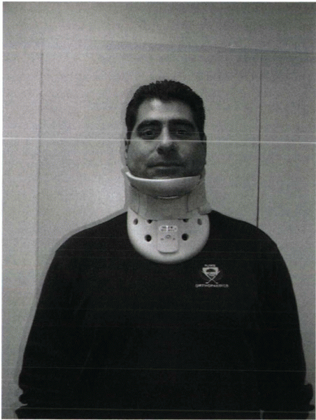
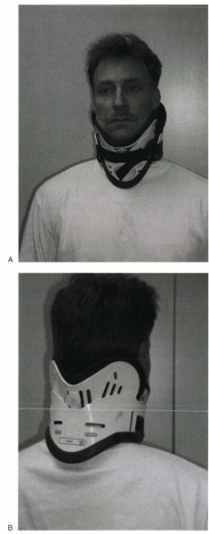
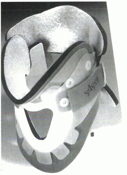
orthoses include the Philadelphia collar (Fig. 32-1), the Miami “J” collar (Fig. 32-2), and the Aspen cervical orthosis (Fig. 32-3).
 |
|
Figure 32-1
Philadelphia collar. Design includes anterior and posterior shells, which are fastened with Velcro straps. The anterior hole is for a tracheostomy tube. |
 |
|
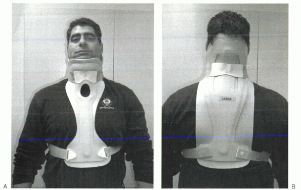
Figure 32-2 Miami “J” cervical orthosis. (A) Frontal view. (B) Posterior view. Design includes anterior and posterior shells with a soft lining that can be changed for hygiene purposes.
|
The methods of this study often have been emulated and its results
frequently quoted since its publication in 1977. The authors evaluated
the soft collar, Philadelphia collar, four-poster orthosis,
sternooccipitomandibular immobilizer (SOMI), and a CTO. They used
radiographs and overhead photographs taken at the extremes of motion in
flexion/extension, rotation, and lateral bending. They quantified
sagittal plane motion for each brace at every level of the cervical
spine. As others had shown, Johnson et al
found that a soft collar offered no restriction of motion in any plane.
They found that increasing the length of the orthosis (extending it
onto the thorax) and increasing the rigidity of the connection improved
the flexion control, but lateral bending and total flexion and
extension were less controlled. They also showed increased motion
between the occiput and C1 in all the braces compared with the unbraced
state. This “snaking” or paradoxical motion subsequently has been
described throughout the cervical and thoracolumbar spine.
orthoses in terms of their efficacy in restricting cervical motion.
Radiographic and goniometer measurements found the NecLoc (Jerome
Medical, Moorestown, NJ) orthosis to be superior to the Miami J,
Philadelphia, Aspen, and Stifneck (Laerdal, Armonk, NY) orthoses in
terms of flexion/extension, rotation, and lateral bending. The Miami J
collar also was found to be significantly superior to the Philadelphia
and Aspen orthoses in extension and combined flexion/extension.
 |
|
Figure 32-3 Aspen cervical collar. Design includes patented tabs that allow the collar to conform better to the patient when tightened.
|
breakdown over bone prominences, such as the occiput, mandible, and
sternum. Skin breakdown is especially prevalent in multitrauma patients
with prolonged recumbency and in patients with altered sensorium. One
study reported orthosis-related decubiti in 38% of patients with
associated severe closed head injuries. Plaisier et al compared the
skin pressure associated with the use of the Stifneck, Philadelphia,
Miami J, and Aspen/Newport collars in supine patients. They found that
the Miami J and the Aspen collar produced the lowest chin and occiput
pressures, both being below the mean capillary closing pressure.
Increased intracranial pressure as a consequence of rigid cervical
orthotic immobilization has been described. Hunt et al studied the
effects of rigid collar placement on intracranial pressure in
head-injured patients. They found that rigid collars cause a small but
significant increase in intracranial pressure, which may have
deleterious effects in patients with severe head injuries and
preexisting intracranial hypertension. Hunt et al recommended early
removal of rigid collars from head-injured patients when cervical spine
injury has been ruled out.
in the field also have been studied extensively, including use of a
cervical collar, a short board or sandbag technique, or a combination
of collar and short board. Cline compared the Hare extrication collar,
the Philadelphia collar, and their immobilization protocol, which
consists of a short board with forehead and chin straps. They concluded
that the short board with straps provided the best immobilization and
that the addition of a Philadelphia collar did not provide additional
benefit. Podolsky et al used goniometry to evaluate the immobilization
provided by a soft collar, hard collar, Philadelphia collar, Hare
extrication device, and their sandbag technique (which uses a board
plus forehead tape). They found that the sandbag technique provided the
most effective immobilization, but that the addition of a Philadelphia
collar provided additional benefit.
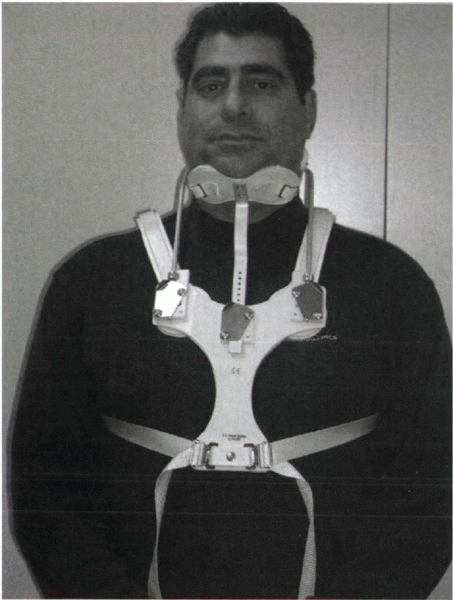
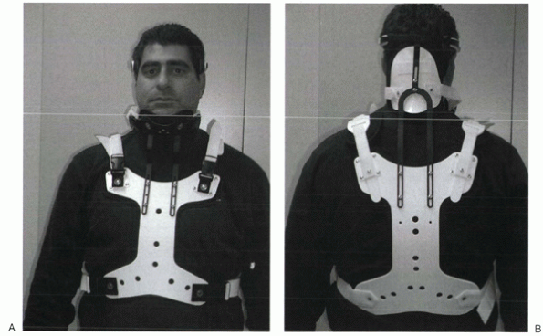
attached to anterior or posterior (or both) thoracic plates. Examples
include the SOMI (Fig. 32-4), the Minerva brace (Fig. 32-5), and the Yale brace (Fig. 32-6).
Compared with cervical orthoses, CTOs improve control in all planes of
motion. This improved rigidity comes at the expense of patient comfort,
however. Some earlier authors distinguished between the two/four-poster
designs and designs with more extensive connections between the head
and thoracic components. The more recent, standardized classification
system categorizes the poster braces as CTOs, however, along
with
the other designs. The traditional four-poster brace was shown to limit
79% of overall cervical flexion/extension and to limit midcervical
flexion to a comparable degree as the more rigid CTOs. Because of their
heavy design and high resting pressures on the chin and occiput, these
braces are used less commonly today.
 |
|
Figure 32-4
Sternooccipitomandibular immobilizer. The three uprights that extend from the mandibular and occipital rests all connect on the anterior thoracic plate. |
 |
|
Figure 32-5 Minerva cervicothoracic orthosis. (A) Frontal view. (B)
Posterior view. The padded, U-shaped hand band is attached to a large occipital flare that has a rigid connection to the posterior thoracic plate. |
metal uprights to connect occipital and mandibular rests to a sternal
plate that is secured to the thorax by padded metal “over-the-shoulder”
straps and additional circumferential straps that cross in the back.
Because there is no posterior thoracic plate, the occipital rests are
supported by uprights from the sternal piece; this results in adequate
control of flexion but deficient control of extension throughout the
cervical spine. These braces generally are associated with fair patient
comfort but also show high resting pressures at the chin and occiput.
plaster jacket that created difficulties in maintaining patient hygiene
and obtaining radiographs. As a result of the difficulties encountered
in managing patients with this device, the halo came into popular use.
Later the thermoplastic Minerva body jacket was developed, which
preserved the noninvasive nature of the original concept. Its
lightweight, bivalved, Polyform shell allowed improved patient comfort
and hygiene and interfered less with follow-up radiographs. Donning
this brace is complex, often requiring an orthotist for proper
application. More recently a prefabricated version of the Minerva body
jacket has been developed, the Minerva CTO (see Fig. 32-5). Its design features a forehead
band attached to a large occipital flare. Sharpe et al showed that this
orthosis limits overall sagittal plane motion by 79%, axial rotation by
88%, and lateral bending by 51%.
 |
|
Figure 32-6 Yale brace. (A) Frontal view. (B)
Posterior view. Note the similarities of the headrest to a Philadelphia collar, from which the early version originally was adapted. |
originally was designed as a modified Philadelphia collar with
custom-molded anterior and posterior polypropylene thoracic extensions.
The modern version is prefabricated and usually made of Kydex. Although
lighter and less cumbersome than most of the other CTOs, the Yale brace
has similar efficacy in controlling motion. In Johnson’s study, the
Yale brace restricted 87% of overall flexion-extension, 75% of axial
rotation, and 61% of lateral bending. Although the CTOs have been shown
to be fairly effective at limiting motion of the cervical spine, they
should not be expected to immobilize rigidly below the C7-T1 level
despite their thoracic components.
most rigid immobilization of the cervical spine of all the currently
used orthoses. Originally inspired by a device used by Bloom to treat
facial fractures in pilots with overlying burns during World War II,
modified versions were used by Nickel and Perry to immobilize patients
with polio who had undergone posterior cervical fusion. The early halo
devices consisted of a circumferential stainless steel ring with four
pins for skull fixation. The ring was attached to a plaster jacket by
upright posts. Numerous improvements have been made to the various
components of the halo vest, but the overall design principles remain
the same. A ring is fixed to the skull with multiple pins. The ring is
attached to a vest by four connecting rods (Fig. 32-7).
Newer rings are made of composite materials, which have the beneficial
properties of light weight, radiolucency, and compatibility with
magnetic resonance imaging (MRI). There does not seem to be a
difference in fixation strength between newer radiolucent graphite
rings and the early titanium ones. Rings that are open posteriorly or
have crown-type designs have been developed. These designs allow for
ease in placement because the head of the patient does not need to be
passed through the ring. Additionally, because the patient is not lying
on the back of the ring, there is less risk of cervical spine fracture
displacement through ring manipulation.
of Paris. With the development of plastic technology, newer
lightweight, easily applied vests of various sizes based on chest
circumference have been developed. Adjustable straps and supports help
customize the fit. The connecting rods have been anodized to prevent
seizing of the metal during tightening. The connecting rods in many
designs are made of carbon fiber for their radiographic lucency and for
compatibility with MRI. Torque wrenches are included in the application
sets to prevent overtightening of the bolts that connect the rods to
the vest and the ring. Mirza et al found that most commercially available vests provide comparable immobilization. Factors that they showed to decrease motion
included increasing vest snugness, decreasing the deformability of the vest, and appropriate fit and application.
 |
|
Figure 32-7 The halo vest (Bremer). This crown-type design allows easier placement in the supine position.
|
halo pin materials and pin design. The current popular pin composition
is stainless steel. Different pin tip designs have been studied to
determine which may provide the greatest resistance to shear frequently
encountered at the pin-bone interface. Interest has arisen regarding a
bullettype tip, which may be able to withstand higher shear forces.
Some systems have torque wrenches that break off at a set torque. These
wrenches are made to be low profile, allowing for ease of usage in
cramped areas, such as the posterior aspect of the skull while the
patient is supine.
related to inappropriate site selection or technique, a thorough
understanding of pin insertion principles is essential. Many years of
clinical data have fine-tuned the optimal location of halo pin
placement. To minimize pin complications but maximize the rigidity of
the halo-vest frame, two anterior and two posterior pins usually are
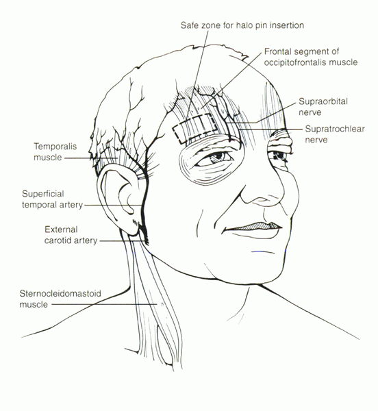
placed. The standard position of the two anterior pins is 1 cm superior
to the orbital rim, over the lateral two thirds of the orbit, being
sure to be below the level of the greatest circumference of the skull (Fig. 32-8).
This is considered the safe zone. In a cadaver study, it was found that
the skull thickness in this region averaged approximately 2 mm for the
outer cortical table and 3 mm for the intercalvarial space or inner
diploë. Pins placed too medial may damage the supraorbital or
supratrochlear nerves. Also, the frontal sinus has a varied position in
the midline. The outer table of the frontal sinus is thin, which can
lead to perforation with medial pin placement. Laterally placed
anterior pins have been proposed over the temporalis fossa to avoid
unsightly scarring over the anterior forehead. At this location,
however, the zygomaticotemporal nerve, which provides sensation to the
area over the temple, may be injured. By entering through the
temporalis muscle, the pin often causes irritation during mandibular
motion. Additionally, in cadaver studies, the skull was found to have a
thin outer and inner table with minimal cancellous diploë in this
region.
anterior pin location. There are no neuromuscular structures at risk,
and the skull has a near-uniform thickness, with the thickest section
being straight posterior. Direct posterior pin placement is avoided
because the patient would lie on this pin in the supine position. The
pins usually are placed diagonally opposite to the anterior pins,
approximately 1 cm superior to the upper helix of the ear. Care must be
taken to avoid any contact between the ring/pin and ear, while
remaining inferior enough below the equator of the skull to prevent
superior pin migration.
to the tangent of the skull may be difficult. Because the halo is not a
static unidirectional device, shear forces act at each of the pin
sites. A biomechanical study looked at the transverse shear forces to
failure of pins placed in decremental angles from 90 degrees, 75
degrees, and 60 degrees. The load to deformity and failure was
substantially higher for pins inserted perpendicular compared with 60
degrees. To avoid the complication of pin loosening, it is imperative
to place these pins perpendicular to the skull to provide the most
strength at the pin-bone interface.
in.-lb were based on empirical observations. Cadaver studies have
shown, however, that 10 in.-lb of pressure barely penetrates the outer
table. Biomechanical testing has shown that 8 in.-lb is more favorable
compared with 6 in-lb in adults. Clinical trials have borne this out
with reduced pin site loosening and infection.
With the cervical spine protected by manual traction, the patient’s
trunk can be elevated 30 degrees for vest placement. The posterior
portion of the vest is applied and connected to the halo, followed by
the anterior portion. Alternative methods include logrolling the
patient, although it may be difficult to maintain cervical alignment.
In rare instances of a stable fracture pattern or after surgical
internal fixation, the patient can be instructed to sit upright, and
the vest can be applied. All the locking bolts are tightened to 28
in.-lb of torque preset on the screwdriver. When all the bolts are
tightened, cervical spine alignment should be confirmed
radiographically.
24 to 48 hours after placement. Studies have documented an immediate 2
to 4 in.-lb decrease in pin fixation purchase after vest placement. A
commonly used pin care regimen
consists
of daily cleansing with dilute hydrogen peroxide (50/50 with water) on
a cotton swab. Patients should have follow-up examinations at
predetermined intervals to confirm lack of halo-vest complications. At
this time, radiographs are taken to confirm adequacy of cervical
immobilization.
 |
|
Figure 32-8 Diagram of the safe zone for placement of anterior halo fixator pins.
|
|
TABLE 32-2 PROCEDURE SUMMARY FOR APPLICATION OF THE HALO SKELETAL FIXATOR
|
||
|---|---|---|
|
for immobilization of the cervical spine, some motion and force
transmission to the cervical elements does occur. In early studies, the
halo device was found to permit only 4% of flexion/extension, 4% of
lateral bending, and 1% of rotational motion of the normal native
cervical spine. Follow-up studies have shown that such significant
immobilization was not accurate, however. One study showed 51 degrees
of motion with halo immobilization. Segmentally the greatest motion is
observed at the occiput-C1 level (11.5 degrees). The lowest is at C2-3
(6.7 degrees). When flexion was observed at one segment of the spine,
extension was observed at another level—a phenomenon called snaking.
Motion of the cervical spine was observed with patient position changes
from supine to prone or from supine to sitting. There was no increased
motion at the level of injury, however. In contrast, a clinical series
reported greater than 3 degrees of angulation and 1 mm of translation
at the fracture site in 77% of the patients.
generated by the halo device. Maximal forces seem to be exerted in the
medial-lateral plane. In daily activities, however, it was observed
that anterior-posterior and vertical forces were much larger. This
observation was confirmed by Lind and Sihlbom, who noted no horizontal
motion in the halo device. They reported significant differences in
distractive forces between the supine and upright positions that can be
attributed to the added weight of the head. Distractive forces were
most increased with deep breathing, shoulder shrugging, and arm
elevation, although no patient experienced any discomfort. These high
distractive forces were most elevated in patients with tight-fitting
vests. It was concluded that the halo vest can be elevated by the
sternum and the scapulae. It was recommended that there be at least 30
mm of space between the sternum and the vest to prevent gross motion of
the vest with daily activities. Patients also should be cautioned
regarding exercises that involve twisting and bending because these
tend to transmit undesirable forces to the cervical spine.
halo device, complications with its use are frequent. Awareness of the
most commonly seen complications can help minimize their severity and
avoid catastrophic sequelae.
common problems with the halo device. In two large studies, pin
loosening was observed in 36% and 60% of patients. This problem was
confirmed experimentally in a biomechanical study in three patients.
There was an 83% decrease in torque pressure measured at the time of
halo removal. The mechanism of pin loosening is thought to be via bone
resorption at the pin tip. If there is no sign of infection, the pins
may be retightened to 8 in.-lb of torque as long as resistance is met
on the first few turns of the pin. If no resistance is met, a new pin
must be placed in an adjacent position. The old pin should be kept in
place until the new pin has been placed rigidly to keep the correct
orientation of the ring on the skull.
approximately 20%. If drainage and erythema continue at a pin site even
with aggressive pin care, bacterial cultures should be obtained, and
appropriate oral antibiotics should be started. If cellulitis persists
or an abscess forms, the pin should be removed and placed in another
position. The patient may require incision and drainage of the abscess
with parenteral antibiotics.
complications often related to patient falls. If a patient reports
trauma to himself or herself or to the halo, radiographs must be taken
tangential to the skull to determine whether pin perforation of the
inner table has occurred. Clinically the patient may present with a
headache, malaise, or visual disturbances if symptomatic pin
penetration has occurred. Clear cerebrospinal fluid leakage from the
pin site is a definitive sign that dural puncture has occurred. In
these circumstances, a new pin should be placed in another region, and
the old pin should be removed. Elevation of the head decreases
intracerebral pressure and facilitates closure of the dural tear. These
tears usually heal in 4 to 5 days. If the tear does not heal or an
infection is suspected (subdural abscess), formal surgical intervention
may be necessary.
halo immobilization. Deglutition dysfunction leading to aspiration has
been reported. Many instances of swallowing difficulty are a result of
the cervical spine’s being immobilized in the extended position.
Efforts to flex the cervical spine while maintaining cervical reduction
may assist in dysphagia resolution.
patients during halo immobilization. These sores frequently develop
underneath the vest or cast vest secondary to pressure against
prominent bone surfaces or are due to insufficient padding or incorrect
sizing of the vest. Principles of pressure sore prevention include
frequent turning, adequate vest padding, and routine skin inspections.
Pressure sores are more prevalent in patient populations using a cast
vest, rather than the padded prefabricated plastic vest; this is
especially important in patients with neurologic deficits, who may not
have adequate sensation over the trunk. Alternative strategies to halo
immobilization, such as rigid internal fixation, should be considered
in these patients. Pressure sore treatment may require split-thickness
skin grafting and rotational muscle flaps for coverage.
of children and infants after unstable cervical injuries and congenital
abnormalities. The recommended pin torque pressure in children is 2 to
5 in.-lb owing to the pediatric skull’s being thinner and softer. In
infants (<3 years old), a multiple, low torque pin system is
recommended to achieve maximal stability.
pressure under general anesthesia. Halo pins should be placed under the
largest diameter of the skull, with care to avoid the frontal sinus and
temporal regions. A computed tomography scan of the head may be
beneficial to identify the location of suture line and bone fragments
(in congenital cases) before placement of the halo. In the presence of
open suture lines and fontanelles, vigilant care must be taken to
ensure that equal pressure is being placed on the skull through the
halo pins symmetrically to prevent skull deformity.
required. When the halo is placed, the vest is applied in normal
fashion and connected to the halo. Children require the same pin care
that adults require. A study has found that children have a higher rate
of pin loosening. It is recommended that children with halo fixators
have close supervision.
patients with unstable cervical injuries may require initial
stabilization or reduction using cervical skeletal traction.
Gardner-Wells
tongs
consist of two pins attached to a bow-shaped frame, through which
traction may be applied. The neutral position for tong placement is at
a level 1 cm posterior to the external auditory canal and 1 cm above
the pinna. Depending on the injury pattern, tongs may be placed
slightly anterior to impart an extension moment or slightly posterior
to impart a flexion moment to the spine. Stainless steel tongs, rather
than MRI-compatible graphite tongs, should be used when high weight
reduction is being attempted. Radiographs should be obtained after the
initial 10 to 15 lb of weight application to rule out occult
occipitocervical injuries, which can be overdistracted easily.
Neurologic status must be monitored for change during and after
application of traction. If definitive treatment is delayed, patients
may benefit from use of rotating beds while traction is maintained.
flexible and rigid variations. The flexible versions have a design
similar to their rigid counterparts but provide only minimal
immobilization. Sacroiliac orthoses generally encircle the pelvis,
spanning the tops of the iliac crests to the trochanters. These may
provide relief in traumatic postpartum separation of the sacroiliac
joints. LSOs extend from the pelvis to the xiphoid anteriorly and the
inferior angle of the scapula posteriorly. TLSOs extend higher,
generally to the midscapular level.
 |
|
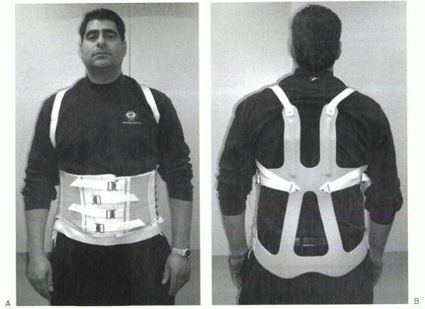
Figure 32-9 Knight-Taylor orthosis. (A) Frontal view. (B)
Posterior view. Control of thoracic sagittal plane motion is achieved through axillary straps attached to posterior thoracic uprights. |
physicians for the treatment of low back pain. These corset-style
devices are adjustable by means of laces, hooks, or Velcro straps. Some
authors have reported that these orthoses decrease the myoelectric
activity of the paraspinal muscles and increase intraabdominal
pressure, possibly resulting in decreased loads on the intervertebral
discs. Others have reported increased myoelectric activity, as measured
through surface electrodes on the paraspinal muscles, when certain
tasks are performed in braced subjects. Less controversy surrounds the
effect on the abdominal muscles, with several authors reporting
decreased measured myoelectric activity with brace wear. Clinical
studies are conflicting regarding the role of lumbar supports for
prevention and treatment of low back pain. Jellema et al performed a
systematic review of the literature to assess this issue. They reviewed
13 studies, most of which they determined were low-quality research.
Regardless, they determined that based on the literature,
there is no strong evidence to support the use of lumbar supports for prevention or treatment of low back pain.
controlling motion in the sagittal plane than in controlling rotation
or lateral bending. The Jewett hyperextension brace is an example of a
non-custom-molded TLSO brace. It applies three-point fixation to the
torso through anterior pads on the symphysis pubis and sternum and a
posterior pad midway between the anterior pads. This arrangement of
forces places the spine in slight extension. Similar to cervical
collars, this brace is best in controlling motion in the
flexion/extension plane and is less effective in controlling lateral
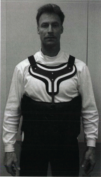
bending and rotation. The Knight-Taylor brace (Fig. 32-9)
is another commonly prescribed TLSO and can be prefabricated or custom
molded. It has a corset-style front for abdominal compression and
lateral and posterior uprights attached to over-the-shoulder straps for
thoracic control. Prefabricated TLSOs often consist of the now common
clamshell brace that can be ordered to measurements and usually are
fabricated out of 1/8-inch to 3/16-inch, lowdensity polyethylene.
Prefabricated “customizable” TLSOs also are commercially available with
apron-style fronts that can be adjusted with Velcro straps and
telescoping sternal pads (Fig. 32-10). These
braces provide good control in all three planes, but the major
restriction is in the flexion/extension plane. For optimal control in
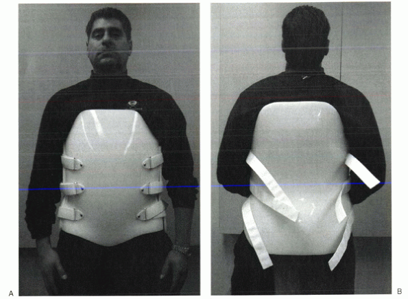
all three planes between T5 and L4, a fully custom-molded TLSO (Fig. 32-11)
should be used. These often are formed from high-temperature
thermoplastic that is custom-fitted from a plastic shell formed from
the patient. When immobilization proximal to T5 is required, a cervical
extension should be included. If immobilization distal to L4 is needed,
a thigh cuff should be added to the orthosis to control pelvic rotation.
performed to evaluate scientifically the ability of external orthoses
to immobilize the thoracolumbosacral spine. Norton and Brown reported
the earliest data on motion restriction with lumbar external supports.
They evaluated three rigid LSOs, one flexible LSO, and a TLSO.
Kirschner wires were inserted into the spinous processes of volunteers.
The angles between the wires were measured to determine the amount of
motion, and radiographic evaluation was performed. They reported
increased motion across the lumbosacral junction in all of the braces.
Increased motion at L4-5 also was noted while the subjects were
sitting. Compared with the unbraced state, all of the braces resulted
in some flexion at L4-5 and L5-S1 while standing. Lumsden and Morris
reported similar findings when they studied lumbosacral rotational
motion in subjects wearing either a chairback brace or LSO corset.
Volunteers had Steinmann pins placed in their posterior superior iliac
spines. Motion was determined by radiographs and measurement of pin
rotation. In each case, the investigators found the braces increased
motion at the lumbosacral level. Fidler and Plasmans used radiographs
to compare the effect on lumbosacral motion of a corset, a brace, and a
plaster jacket with and without a thigh cuff. They found the
custommolded plaster jacket to provide the best immobilization at the
L1-3 level. To improve immobilization at the L4-S1 levels, they
recommended adding a thigh cuff to the orthosis.
 |
|
Figure 32-10
Prefabricated “customizable” thoracolumbosacral orthosis. This particular design (Orthomerica) has an apron-style front with an adjustable sternal pad to help customize the fit. |
cervical orthoses. As mentioned previously, bracing for compression
fractures of the thoracolumbar spine is not tolerated well by elderly
patients. Treatment in these patients usually consists of early
mobilization and close follow-up. A soft binder or corset may provide
support and symptomatic relief. In younger patients, however, anterior
column fractures often are the result of greater energy than their
osteoporotic counterparts, and a more cautious approach often is
favored. These patients commonly are treated with a rigid Jewett or
Knight-Taylor brace. The need for rigid bracing of these fractures is
still a matter of debate, however. A study retrospectively reviewed the
outcome of 129 young patients with mild compression fractures who were
treated with or without a Jewett hyperextension brace. They found that
one-column fractures of the thoracolumbar spine with 30% compression
can be treated safely without bracing, instead prescribing early
ambulation, hyperextension
exercises,
and close follow-up. Burst fractures constitute another entity in the
spectrum of thoracolumbar injuries. Historically, neurologically intact
patients with burst fractures were treated with bed rest for 4 to 12
weeks, followed by progressive mobilization. Today, controversy exists
as to which injuries require surgical stabilization and which can be
treated with bracing and early mobilization. Most would agree that any
neurologic deficit is an indication for operative management. Canal
compromise of 50% or more, kyphotic deformity of greater than 30
degrees, and posterior column involvement are other indications for
aggressive intervention. The final determination often remains a
case-by-case, multifactorial judgment call, however, on the part of the
treating surgeon. Chow et al retrospectively studied functional
outcomes in 24 patients treated with hyperextension body casts or
Jewett hyperextension braces for thoracolumbar burst fractures. None of
these patients had posterior column fractures, significant kyphosis, or
neurologic deficit. Patients initially were treated with bed rest and
logroll precautions until the predictable ileus and abdominal
distention resolved 2 to 3 days later. At that point, patients were
casted or braced and progressively mobilized. Patients were followed
for a minimum of 1 year. The investigators concluded that
hyperextension casting or bracing with early mobilization reduces
hospital time, avoids costs and risks of surgery, and allows patients a
relatively early return to work. Additionally the authors mentioned
that patients treated nonoperatively tended to experience moderate back
pain for 1 year after the injury and that this pain eventually
diminished over time.
 |
|
Figure 32-11 Custom molded thoracolumbosacral orthosis. (A) Frontal view. (B) Posterior view. This bivalve design is made from a plaster cast of the patient.
|
prescribed for treatment after arthrodesis for degenerative conditions.
As discussed earlier, several studies show little or no immobilizing
effect from wearing LSOs and possibly an increase in L4-5 and L5-S1
motion after application of these orthoses. The point continues to be
debated. Postlumbar fusion bracing is believed by some to help relieve
pain and decrease the risk of pseudarthrosis and fixation failure and
is prescribed by some surgeons for 12 weeks postoperatively. Others
believe that LSOs do little to immobilize the lumbar spine, and rigid
operative fixation is enough to produce good patient outcomes.
the management of traumatic and degenerative conditions. Many different
types are commercially available, and the scientific evidence to
document their effectiveness is variable.
Despite
the potential for complications, the halo remains the gold standard for
external cervical immobilization. A thorough appreciation of the
biomechanics of spinal orthoses and their potential complications can
help maximize their utility and minimize associated morbidity.
 |
|
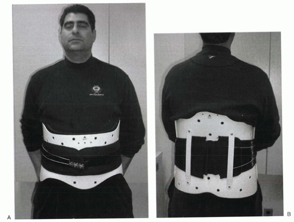
Figure 32-12 Prefabricated lumbosacral orthosis. (A) Frontal view. (B)
Posterior view. This design (Calfornia Compression Jacket, Orthomerica) has a patented “rip cord” used to help adjust the snugness of the fit. |
Precision Orthotics and Prosthetics, Linden, NJ. The models wearing the
braces are Paul Goodman, CO, and David Sussman, CPO, both of Precision
Orthotics and Prosthetics. We greatly appreciate their contribution to
this chapter.
V, Eismont FJ. Efficacy of five cervical orthoses in restricting
cervical motion: a comparison study. Spine 1997;22:1193-1198.
MJ, Garfin SR, Byrne TP, et al. The halo skeletal fixator: principles
of application and maintenance. Clin Orthop 1989;239: 12-18.
MW, Plasmans CMT. The effect of four types of support on the segmental
mobility of the lumbosacral spine. J Bone Joint Surg Am 1983;65:943-947.
RM, Hart DL, Simmons EF, et al. Cervical orthoses: a study comparing
their effectiveness in restricting cervical motion in normal subjects.
J Bone Joint Surg 1977;59A:332-339.
AA, Panjabi, MM. Physical properties and functional biomechanics of the
spine. In: White AA, Panjabi MM, eds. Clinical Biomechanics of the
Spine, 2nd ed. Philadelphia: JB Lippincott, 1990.