
of the articulated external fixator: (a) to allow active or passive
motion, (b) to protect the articular surface and the collateral
ligaments.
-
Coronoid fracture with or without fixation.
-
Olecranon fracture with tenuous fixation.
-
Distal humeral articular fractures.
-
Unstable ulnohumeral joint after acute collateral ligament disruption.
-
Combination of instability with any of the preceding fractures (complex instability).
but occasionally is used with inflammatory stiffness. The use of
distraction is generally indicated in these circumstances.
-
There has been a significant amount of dissection, suggesting that maintaining the intraoperative motion will be difficult.
-
If the pathology has modified the joint
contour, requiring refashioning of the joint surface, with or without
an interposition membrane. -
When an interposition procedure is performed.
-
If the collateral ligament has been reconstructed or repaired in association with the release.
-
Inexperience with the use of external
fixation devices is considered a relative contraindication. Application
of this device is technically demanding and requires accurate placement
of the skeletal pins. -
If uncertainty exists with regard to the
anatomic location of the neurovascular structures due to posttraumatic
destruction of the joint, the distraction device should be used only
with extreme caution. (The pins, under these circumstances, may be
inserted under direct vision.) -
Local sepsis is a relative contraindication to the application of this device.
-
The presence of some fracture fixation devices in the distal humerus or proximal ulna.
-
Preemptive medical condition (e.g., severe osteoporosis).
rigid skeletal fixation can be obtained by use of an articular device
that replicates the axis of rotation.
Distractor (DJD) II allows protection or neutralization of the
articular surface for a variety of clinical circumstances.
 |
|
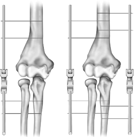
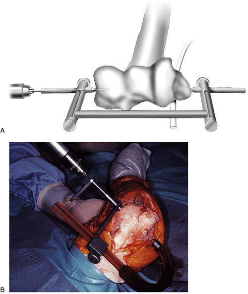
Figure 8-1.
Half- and full-pin fixation with uni- or bilateral frame application offers significant application flexibility and clinical uses for the DJD II. |
encumbrance, particularly in both the articular surface and the
collateral ligaments.
used in either a monolateral or a bilateral configuration. This allows
a great deal of flexibility of use and indications (Fig. 8-1).
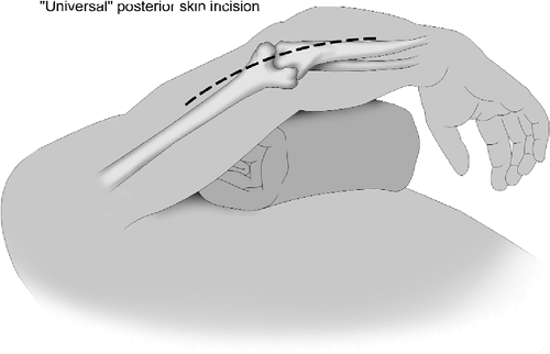
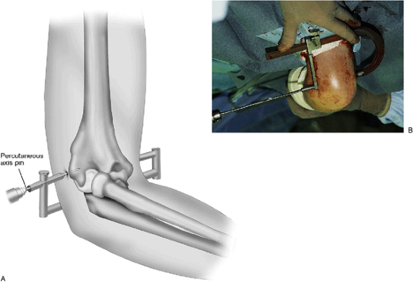
scapula. The arm is draped free with a nonsterile tourniquet and is
brought across the chest (Fig. 8-2). The elbow
is exposed according to the pathology present. Regardless of the
exposure or pathology, the essential landmarks for axis pin placement
are critical.
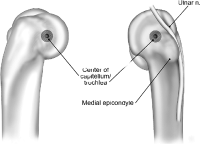
present at the site of the origin of the lateral collateral ligament.
This tubercle also represents the geometric center of curvature of the
capitellum, which is the site of the flexion axis of the elbow and is
the point through which a 3-mm Apex humeral reference pin will pass (Fig. 8-3).
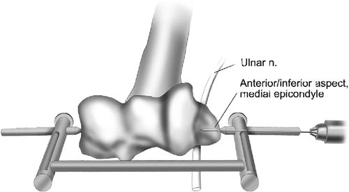
rotation lies just anterior and inferior to the medial epicondyle. The
axis pin is placed in this region or slightly anterior and proximal to
this location (Fig. 8-3). This represents a safe zone relative to the ulnar nerve.
For a lateral frame application a 3-mm Apex humeral reference pin is
drilled or tapped 10 to 20 mm into the distal humerus. If there is
gross distortion, the center of the trochlea is the desired location
for the pin, since the ulna rotates on the humerus and rotation on the
capitellum is a secondary feature. If a medial frame is to be applied,
the ulnar nerve is identified and protected at the time of insertion of
the 3-mm Apex humeral reference pin.
or a triceps reflection technique (Chapters 1 and 4).
If the fracture fixation device(s) or collateral ligament reattachment
precludes the introduction of a 3-mm axis pin, a small Kirschner wire
is inserted in a manner to replicate the axis of rotation.
 |
|
Figure 8-2. The patient is supine, the arm is brought across the chest, and most commonly a posterior skin incision is employed.
|
 |
|
Figure 8-3.
The axis landmark on the distal humerus laterally is the axis of the projected center of the capitellum. Medially, the axis is at the anterior inferior aspect of the medial epicondyle. |
previous incision is entered, and an extensile lateral Kocher-type
joint release is used.
olecranon (Mayo Modified Kocher). However, in some instances, such as
when elbow flexion is normal, the triceps may be left intact. The
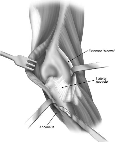
capsule is exposed by releasing the common extensor tendon. If the
pathology is extrinsic to the joint, the anterior capsule is excised
but the lateral collateral ligament is preserved. If the joint is
abnormal and is to be altered, as with an interposition arthroplasty,
the lateral collateral ligament is elevated as a flap of tissue from
its origin at the lateral condyle. This is tagged and reflected
distally, providing an extensive exposure (Fig. 8-4), but must be repaired and reattached at closure.
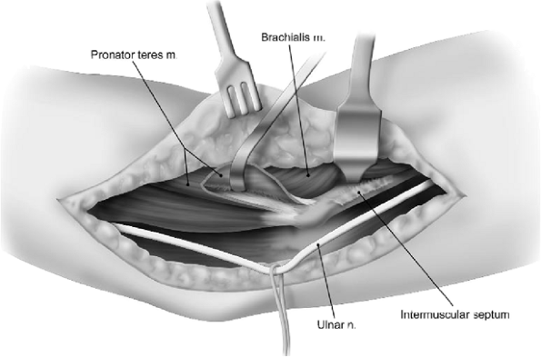
requires an extensive dissection, the identification and protection of
the ulnar nerve is necessary. Ideally, a single posterior incision is
utilized, and a subcutaneous dissection is carried out to the medial
aspect of the triceps. If a previous Kocher skin incision has been
placed laterally, ulnar nerve exposure is accomplished through a
supplemental medial incision. In any event, the ulnar nerve is
identified but is usually not translocated anteriorly. Instead, it is
simply protected, first during the capsular dissection and later at the
time of axis pin placement. If ulnar nerve symptoms are present, then
the nerve is decompressed with definitive management, according to the
dictates of the pathology.
holes are made distal and proximal to the axis site for reattachment of
the lateral collateral ligament (Fig. 8-5).
Bunnell or Krachow sutures are placed through the radial (lateral)
ulnar collateral ligament and through the holes drilled through the
lateral column around the flexion pin.
-
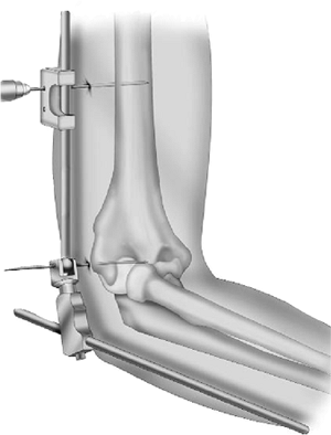
Axis of rotation.
Determine the axis of rotation external landmarks and place the humeral
(axis) reference pin guide in line with the axis of rotation. The tip
of the guide
P.143
is usually placed on the medial side while the pin guide on the lateral side as the axis pin enters laterally (Fig. 8-6).![]() Figure 8-4.
Figure 8-4.
An extensile surgical exposure typically involves elevating the sleeve
of extensor muscles and releasing the lateral collateral ligament. -
Reference pin that acts as a guide during frame construction.
Insert laterally the 3-mm-diameter self-drilling/self-tapping Apex pin
through the humeral (axis) reference pin guide in the axis of rotation.
For monolateral frame construction insert the pin to a depth of 15 to
20 mm. For bilateral frames it is recommended to replace the 3-mm Apex
humeral reference pin by a 3-mm smooth transfixing Apex pin that is
inserted across the distal humerus (see “Bilateral Frame Option”).Note: The 3-mm pin is a reference pin and is the essential reference required to accurately
P.144
assemble the DJD II frame and to properly insert the humeral and ulnar pins. It will be removed after frame construction.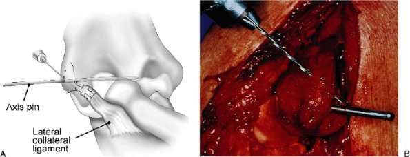 Figure 8-5. A,B: Holes that are placed around the axis of rotation allow the ligament to be reattached with an osseous attachment.
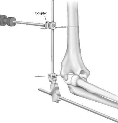
![]() Figure 8-6. A,B:
Figure 8-6. A,B:
The C-guide with the sharp tip placed medially under direct vision
allows accurate orientation of the axis reference pin even if placed
only partially across the joint. -
Remove the humeral (axis) reference pin guide.
-
Placement of the DJD II frame on the reference pin.
The hollow-bored hinge of the DJD II is placed over the reference pin
so that its hinge is exactly in the same axis of rotation as the
natural axis of rotation of the elbow. Verify that the distraction
device is fully compressed before frame construction. -
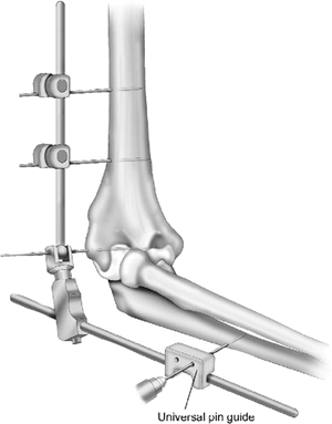
Pin insertion.
At this stage, depending on surgeon preference or features of the case,
one may insert either the humeral or the ulnar pins. Humeral pin
insertion is the author’s choice. -
Humeral pin insertions.
-
Apply the 3-mm or 4-mm drill guide over the humeral rod so that pin guide is aligned with the lateral humerus (Fig. 8-7).Note: The 5-mm humeral rod is aligned to the anterior cortex of the humerus (INSERT).
-
The proximal humeral
self-drilling/self-tapping Apex 4-mm (or 3-mm) pin is inserted into the
lateral cortex of the humerus through the pin guide and engages the
opposite cortex. -
The pin guide is then removed.
-
The proximal pin is fixed to the humeral
rod with a Hoffmann II Compact pin-to-rod coupling that is then
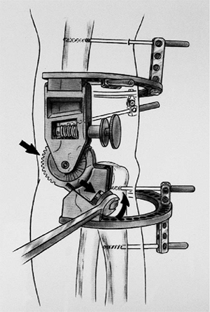
tightened using a Hoffmann II Compact wrench (Fig. 8-8).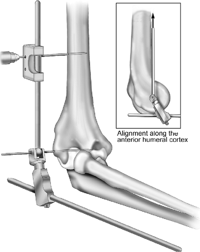 Figure 8-7.
The fixator is placed over the reference pin, and using the alignment
guide a proximal half-pin is placed through the lateral and medial
humeral cortices. The humeral arm of the fixator aligns with the
anterior cortex of the humerus (INSERT).P.145Note: Hoffmann II Compact pin-to-rod couplings accept pins of both 3 and 4 mm in diameter. -
Place the pin guide over the humeral rod more distally (closer to the hinge).
-
The second self-drilling/self-tapping Apex 4-mm (or 3-mm) pin is now inserted more distally through the pin guide (Fig. 8-9).Note: The pins need not
necessarily be parallel. If a different pin insertion angulation is
required to access a more desirable area on the humerus, slightly (5
degrees) rotate the pin guide over the humeral rod until such a pin
insertion area can be reached. By ensuring proper pin/rod distance, the
system allows independent pin placement that is not coplanar (INSERT). -
The pin guide is then removed from the humeral rod.
-
The distal pin is fixed to the humeral
rod with a Hoffmann II Compact pin-to-rod coupling that is then
tightened using a Hoffmann II Compact wrench.
-
-
Ulnar pin insertions.
-
According to the pin diameter (3 or 4
mm), place the appropriate pin guide over the ulnar rod to access the
lateral aspect of the ulna.Note: Three-millimeter pins are usually preferred, as the ulna diameter is smaller.![]() Figure 8-8. The proximal pin is fixed to the humeral rod with the H2C coupling mechanism.
Figure 8-8. The proximal pin is fixed to the humeral rod with the H2C coupling mechanism. -
The distal ulnar
self-drilling/self-tapping Apex 3-mm (or 4-mm) pin is inserted into the
lateral cortex through the pin guide and pierces the medial ulnar
cortex (Fig. 8-10). -
The pin guide is then removed.
-
The distal pin is fixed to the ulnar rod
with a Hoffmann II Compact pin-to-rod coupling, which is then tightened
using a Hoffmann Compact wrench. -
Place the pin guide over the ulnar rod more proximally (i.e., between the distraction mechanism and the distal pin).
-
The proximal self-drilling/self-tapping Apex pin can now be inserted through the pin guide (Fig. 8-11).Note: As at the humerus, the
pins are not necessarily parallel. If a different pin insertion
angulation is required to reach a more adequate pin insertion area,
slightly rotate the pin guide over the ulnar rod until such a pin
insertion area can be reached. The system allows an independent pin
placement (Fig. 8-9). -
The ulnar pin guide is then removed.
-
The proximal pin is fixed to the ulnar
rod with a Hoffmann II Compact pin-to-rod coupling, which is then
tightened using a Hoffmann II Compact wrench. -
If the indication requires the use of the proximal ulnar pin in the olecranon, it can be
P.147P.148P.149
inserted through the pin guide. This pin will be once again attached to
the ulnar rod with a Hoffmann II Compact pin-to-rod coupling, which is
then tightened.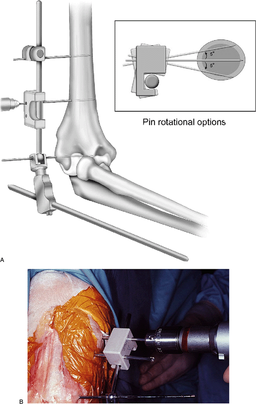 Figure 8-9. A,B:
Using the pin guide, a second half-pin is placed across the proximal
humerus distal to the first. If needed, a plus/minus 5 degrees of
out-of-plane rotation may be introduced to provide better target as
well as avoid soft-tissue injury (INSERT).![]() Figure 8-10. A distal ulna half-pin is applied with the use of the pin guide. Typically, the 3-mm guide is used.
Figure 8-10. A distal ulna half-pin is applied with the use of the pin guide. Typically, the 3-mm guide is used.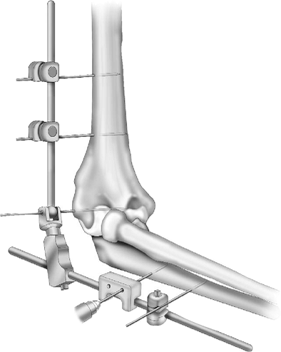 Figure 8-11. After the distal pin has been coupled with the ulnar rod, a second pin is placed using the pin guide.
P.146 -
-
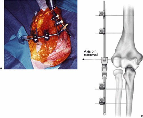
Reference pin removal. The 3-mm Apex humeral reference pin is then removed (Fig. 8-12).
-
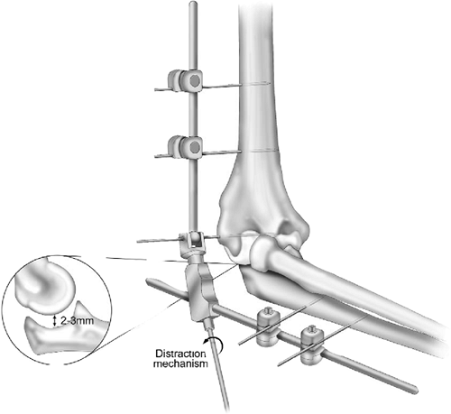
Distraction.
The ulna is separated from the humerus by turning the distraction screw
using a Hoffmann II Compact wrench. Most commonly, 2- to 3-mm
distraction is sufficient to accomplish the goals of the procedure (Fig. 8-13). Skin closure is usually deferred until the distraction is applied.
a second half frame is applied over the smooth transfixing Apex pin on
the medial aspect. Independent half-pins are then applied on both the
humerus and the ulna as described in steps 6 and 7 (Fig. 8-1).
used, especially if ulnar nerve symptoms are present. The medial aspect
of the triceps is identified along with the ulnar nerve. The nerve is
not necessarily transposed unless appropriate for the case. The
intermuscular septum is identified proximal to the epicondyle and
followed anteriorly to the humerus. The soft tissues are elevated from
the distal humerus, and the pronator attachment is released
from
the anterior superior aspect of the medial epicondyle. Elevating the
soft-tissue sleeve allows exposure of the anterior medial capsule (Fig. 8-14).
 |
|
Figure 8-12. A,B: The reference (axis) pin is removed, leaving no interarticular fixative device.
|
 |
|
Figure 8-13.
Using the hand wrench the distraction device is advanced 2 to 3 mm or until the flexion arc occurs without evidence of articular contact. |
reference pin guide in line with the axis of rotation. The guide stylus
is placed medially, and the point is placed laterally at the axis site
located at the lateral tubercle. Insert medially the 3-mm Apex humeral
reference pin (Fig. 8-15). The application
proceeds as with the lateral description. However, care must be
exercised to observe and protect the ulnar nerve and anterior
neuromuscular bundle at the time of humeral pin insertion. This is best
done by directly observing the entrance site of the percutaneous pins
at the humerus (Fig. 8-16).
is unstable, there is a tendency for the ulna to sublux posteriorly. In
these cases, the DJD II may be applied to neutralize this tendency. The
typical features of the application under these circumstances include
the following:
-
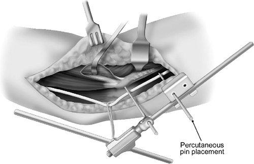
The use of fluoroscopy, so that the pins may be inserted percutaneously.
-
Insertion of the pins distal to the
coronoid to avoid any fracture fixation that may be present, but also
to apply the correct distal displacement vector to help accomplish
elbow joint reduction.
fluoroscopic unit is also draped in a sterile fashion. It may be
difficult to palpate the lateral epicondyle if there is a significant
amount
of swelling. Thus the location in the midpoint of the lateral
epicondyle is identified by AP and lateral projections, using a
hypodermic needle or Steinmann pin to identify the point of insertion.
 |
|
Figure 8-14.
After identification of the medial intermuscular septum the pronator origin and brachialis are swept from the anterior aspect of the distal humerus. |
 |
|
Figure 8-15.
The axis pin is passed through the axis of rotation from medial to lateral using the alignment guide and medial axis target area past the inferior aspect of the medial epicondyle. |
 |
|
Figure 8-16. The humeral pins medially are most safely placed percutaneously under direct vision.
|
 |
|
Figure 8-17. A,B: Percutaneous application directs the reference axis pin from the lateral epicondyle toward the medial epicondyle.
|
laterally and directed toward the point identified at the medial
epicondyle (Fig. 8-17). The DJD II is then
applied over the reference pin, and the humeral half-pins are inserted
percutaneously using the appropriate pin guide (see the preceding step
6) (Fig. 8-18). Hoffmann II Compact pin-to-rod
couplings are used to attach the humeral pins to the humeral rod of the
DJD II. The joint is reduced as able and the ulnar pins are then
applied with the appropriate pin guide. Ulnar pins are then attached to
the ulnar rod with Hoffmann II Compact pin-to-rod couplings.
before the frame is secured; however, small adjustments to alignment
can be made by advancing the distraction mechanism (Fig. 8-19).
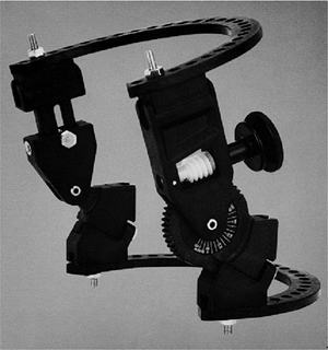
In most instances, the 150-mm ring size is the best. The geared
component is always medial; the knob is always posterior (Fig. 8-20).
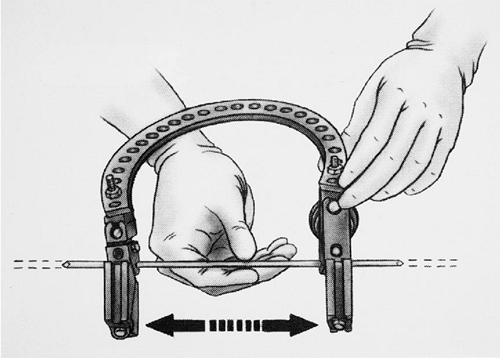
assembled and adjusted, it will slide along the axis pin without
significant impingement or resistance (Fig. 8-21).
The clinician should make sure to allow for swelling in the
postoperative period, allowing at least 2 cm of clearance from the skin
to the hinge block at the time of surgery.
bone, the patient is placed in the supine position with the arm on a
radiolucent hand table. If the patient first requires a more
extensive
exposure of the distal humerus for fracture or reconstructive
procedure, it may be useful to begin the operation with the arm over
the chest, using one of the more standard posterior approaches to the
elbow, either olecranon ostectomy or triceps-sparing exposure if
Bryan/Morrey or a Mayo Modified Kocher release (see Chapter 1).
In cases of gross instability, the prone position can be used; however,
exposure of the coronoid is quite difficult in this position.
 |
|
Figure 8-18.
The proximal half-pin is inserted in a percutaneous fashion (of right arm). Fluoroscopy is recommended for assistance as necessary. |
 |
|
Figure 8-19. After application of the apparatus, the joint is distracted according to the needs of the pathology.
|
 |
|
Figure 8-20. The Compass hinge employs hemi-rings and a gear mechanism that allows free motion on applied force across the mechanism.
|
 |
|
Figure 8-21. The preconstructed frame allows free slide of the axis pin.
|
placed across the joint, or two half-pins can be inserted, one from the
medial and the other from the lateral aspect of the joint. The
alignment of the axis is crucial. It is important to take the time
necessary to achieve perfect placement of this pin for alignment of the
Compass hinge at the elbow. Anteroposterior and lateral radiographs
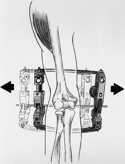
ensure adequate placement. Once the two pins are coincident, the frame
should still be easy to slide from medial to lateral, back and forth,
before securing the axis pin from the medial side (Fig. 8-22).
the humerus in two planes, without impaling any of the major
muscle/tendon units or jeopardizing any neurovascular structures. It is
helpful to be familiar with half-pin systems. If internal fixation is
present, the pin placement can be adjusted to avoid the plates by
customizing the frame. In general, two 5-mm half-pins, medial and
lateral, are required. In larger elbows or in cases in which internal
fixation precludes use of the described sites, a third humeral pin may
be used, usually placed laterally, superior to the spiral groove.
two-hole Rancho cube on the undersurface of the upper ring. Both
cortices should be engaged.
the lateral supracondylar ridge, directed anterior and distally. The
radial nerve, at this level, is anterior to the pin. Humeral fixation
and alignment of the axis of the hinge must be achieved before fixation
of the ulna.
 |
|
Figure 8-22. Once applied, the frame must freely slide from medial to lateral.
|
 |
|
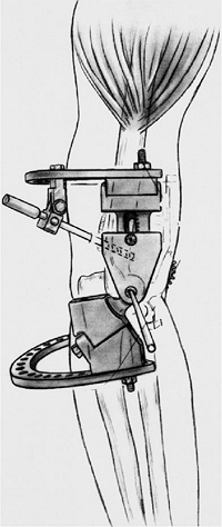
Figure 8-23. The initial fixation is with a lateral half-pin commonly deviated medially at the lateral humeral flare.
|
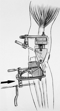
The more proximal pin (5-mm) provides optimal control of the joint and
is placed form the dorsal surface through the coronoid (Fig. 8-24).
The smaller (4-mm) pins are used more distally in the ulna, again from
the dorsal surface. If the elbow is grossly unstable, it is quite
important to reduce the elbow by placing it in approximately 90 degrees
of flexion when applying the ulnar fixation. Once the joint is reduced
and held in position, the first two proximal ulnar pins can be placed.
Once the first two pins are in place, ranging through flexion and
extension and ensuring reduction of the joint is important. If there is
a tendency for the elbow to subluxate, then alignment has not been
achieved and the bolts must be loosened and reduction achieved.
 |
|
Figure 8-24. Proximal and distal ulnar pins are used to stabilize the frame to the ulna.
|
 |
|
Figure 8-25. Distraction is accomplished by rotating the bolts near the ulnar ring fixation blocks.
|
distraction can be applied to the system through the distraction
mechanism. Distraction is achieved by turning the bolts located on the
ulnar ring fixation blocks (Fig. 8-25). Both
sides of the hinge should be distracted an equal amount. Use and extent
of distraction should be done at the discretion of the surgeon.
postoperatively, but this plan is individualized according to the
specific needs of the case.
-
The patient is assessed in the recovery room to ensure neurovascular competence.
-
To avoid unwanted joint movement during
the first 24 hours, the external fixator can be locked by the specific
mechanism of either device. A Hoffmann II Compact rod is placed between
the proximal humeral rod and the distal ulnar rod of the DJD II. The
Compass hinge can also be locked at the distraction if desired. -
If the procedure requires early motion
and complete relief of pain, appropriate analgesia should be provided
to attain this goal. We often employ a brachial plexus catheter for
this purpose. -
The patient is encouraged to begin passive range of motion during the first 24 to 48 hours.
-
A careful inspection of the elbow is made
to assess for swelling and to ensure that the device is not exerting
pressure on the skin. -
Proper pin site care is necessary to reduce the risk of pin tract infection.TABLE 8-1.
Post-op management Time period Axillary block Recovery room to 48 hours CPM Day 1–4: Hospital—then
Day 4–21: Stiffness
Day 4–42: FractureRemoval of distractor 3 weeks, soft tissue
6 weeks, fractureFlexion and extension splints program 12 weeks
21 hr/d, 3 weeks
18 hr/d, 3 weeks
15 hr/d, 6 weeksLong-term splints Maintenance (night)
3 months
(longer as needed) -
If there is no evidence of infection and
there has been adequate progress, the patient is dismissed upon
surgeon’s discretion with active or passive range-of-motion
instructions. -
Approximately 3 weeks after the operative
procedure for stiffness and 6 weeks after treatment of fracture, before
the fixator is completely removed, the elbow is examined for stability.
Care is taken not to forcefully manipulate the elbow. If the elbow is
found to be unstable with the DJD II, the ulnar rod is reattached to
the ulnar pins. If the elbow is stable, the fixator may be removed as
well as the ulnar and humeral pins.
ensure that the elbow is adequately reduced and stable. The patient is
then treated with flexion and extension splints according to the merits
of the case (Table 8-1).
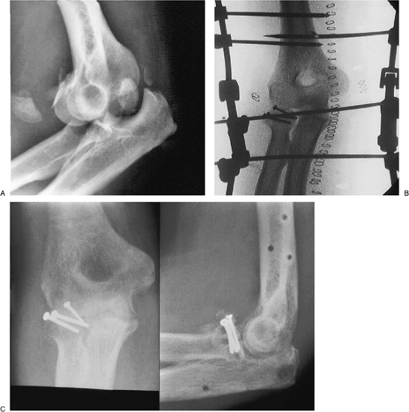
a type III radial head fracture. The subluxation persisted for 3 weeks
before treatment (Fig. 8-26A). The fracture was managed
with osteosynthesis (Fig. 8-26B). The construct was protected or “neutralized” by the DJD II (Fig. 8-26C).
 |
|
Figure 8-26. Complex dislocation with a Mason III radial head fracture dislocation (A).
The fracture is fixed with intrafragment compression osteosynthesis and the construct is stabilized by the DJD II external fixator (B). The fracture healed with an arc of 20 to 140 degrees of flexion and no pain (C). |
MM, Sotereanos DG, Plakseychuk A. Technique for ensuring ulnohumeral
reduction during application of the Richards compass elbow hinge. Am J Orthop 1997;26:646.