
deformities. Deformities are described in terms of abnormalities of
length, angulation, rotation, and translation. The location, magnitude,
and direction of the deformity complete the characterization of the
malunion. Proper evaluation allows the surgeon to determine an
effective treatment plan for deformity correction.
all available medical records, including the date and mechanism of
injury of the initial fracture and all subsequent operative and
nonoperative interventions. The history should also include
descriptions of prior wound and bone infections, and prior culture
reports should be obtained. All preinjury medical problems,
disabilities, or associated injuries should be noted. The patient’s
current level of pain and functional limitations as well as medication
use should be documented.
performed. The skin and soft tissues in the injury zone should be
inspected. The presence of active drainage or sinus formation should be
noted.
out motion and assess pain. In a solidly healed fracture with
deformity, manual stressing should not elicit pain. If pain is elicited
on manual stressing, the orthopaedic surgeon should consider the
possibility that the patient has an ununited fracture.
of active and passive motion of the joints proximal and distal to the
malunion site should be performed. Reduced motion in a joint adjacent
to a malunion site may alter both the treatment plan and the
expectations for the ultimate functional outcome. Patients who have a
periarticular malunion may also have a compensatory fixed deformity at
an adjacent joint, which must be recognized to include its correction
in the treatment plan. Correction of the malunion without addressing a
compensatory joint deformity results in a straight bone with a
maloriented joint, thus producing a disabled limb. The limb may appear
aligned in these cases, but x-ray evaluation will reveal the joint
deformity. If the patient cannot place the joint into the position that
parallels the deformity at the malunion site (e.g., evert the subtalar
joint into valgus in the presence of a tibial valgus malunion), the
joint deformity is fixed and requires correction (Fig. 26-1).
the type and severity of the initial bony injury. Subsequent plain
radiographs show the status of orthopaedic hardware (e.g., loose,
broken, undersized) as well as document the timing of removal or
insertion. The evolution of deformity—gradual versus sudden, for
example—should be evaluated.
Anteroposterior (AP) and lateral radiographs of the involved bone,
including the proximal and distal joints, are used to evaluate the axes
of the involved bone; manual measurement of standard radiographs or
computer-assisted measurement of digital radiographs may be used with
equivalent accuracy.88,92,99 Bilateral
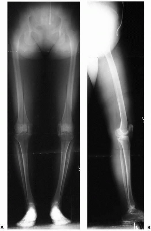
AP and lateral 51-inch alignment radiographs are obtained for lower extremity deformities to evaluate limb alignment (Fig. 26-2). Flexion/extension lateral radiographs may be useful to determine the arc of motion of the surrounding joints.
 |
|
FIGURE 26-1
Angular deformity near a joint can result in a compensatory deformity through a neighboring joint. For example, frontal plane deformities of the distal tibia can result in a compensatory frontal plane deformity of the subtalar joint. The deformity of the subtalar joint is fixed (A) if the patient’s foot cannot be positioned to parallel the deformity of the distal tibia or flexible (B) if the foot can be positioned parallel to the deformity of the distal tibia. |
following characteristics: limb alignment, joint orientation, anatomic
axes, mechanical axes, and center of rotation of angulation (CORA).
Normative values for the relations among these various parameters10,72 are used to assess deformities.
frontal plane mechanical axis of the entire limb rather than single
bones.35,45,47,77,78,90
In the lower extremity, the frontal plane mechanical axis of the entire
limb is evaluated using the weight-bearing AP 51-inch alignment
radiograph with the feet pointed forward (neutral rotation).41,49,82
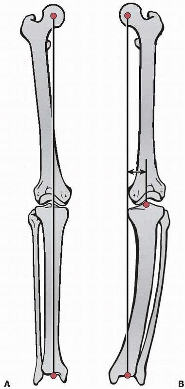
Mechanical axis deviation (MAD) is measured as the distance from the
knee joint center to the line connecting the joint centers of the hip
and ankle. The hip joint center is located at the center of the femoral
head. The knee joint center is half the distance from the nadir between
the tibial spines to the apex of the intercondylar notch on the femur.
The ankle joint center is the center of the tibial plafond.
MAD greater than 15 mm medial to the knee midpoint is varus
malalignment; any MAD lateral to the knee midpoint is valgus
malalignment.
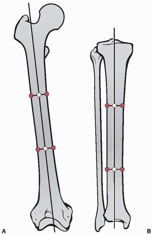
bones are assessed in both the frontal plane (AP radiographs) and
sagittal plane (lateral radiographs). The anatomic axes are defined as
the line that passes through the center of the diaphysis along the
length of the bone. To identify the anatomic axis of a long bone, the
center of the transverse diameter of the diaphysis is identified at
several points along the bone. The line that
passes through these points represents the anatomic axis (Fig. 26-4).
 |
|
FIGURE 26-2 A. Bilateral weight-bearing 51-inch AP alignment radiograph and (B) a 51-inch lateral alignment radiograph, which are used to evaluate lower extremity limb alignment.
|
 |
|
FIGURE 26-3 A. Mechanical axis of the lower extremity, which normally lies 1 mm to 15 mm medial to the knee joint center. B.
Medial mechanical axis deviation, in which the mechanical axis of the lower extremity lies more than 15 mm medial to the knee joint center. |
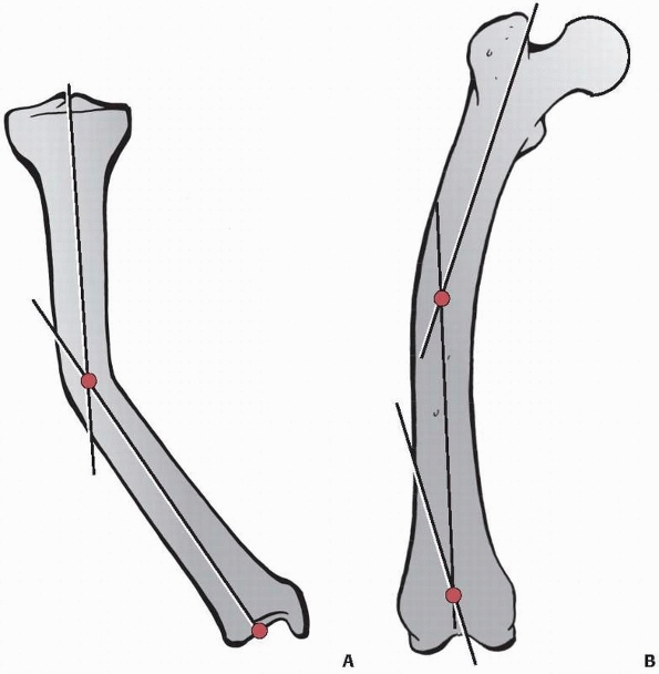
line. In a malunited bone with angulation, each bony segment can be
defined by its own anatomic axis with a line through the center of the
diameter of the diaphysis of each bone segment representing the
respective anatomic axis for that segment (Fig. 26-5). In bones with multiapical or combined deformities, there may be multiple anatomic axes in the same plane.
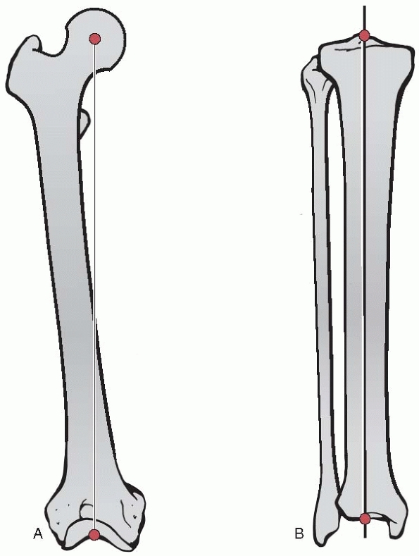
line that passes through the joint centers of the proximal and distal
joints. To identify the mechanical axis in a long bone, the joint
centers are connected by a line (Fig. 26-6). The mechanical axis of the entire lower extremity was described above under the heading “Limb Alignment.”
the respective anatomic and mechanical axes of a long bone. Joint
orientation lines are drawn on the AP and lateral radiographs in the
frontal and sagittal planes, respectively.
 |
|
FIGURE 26-4 A. Anatomic axis of the femur. B. Anatomic axis of the tibia.
|
frontal plane. The trochanter-head line connects the tip of the greater
trochanter with center of the hip joint (the center of the femoral
head). The femoral neck line connects the hip joint center with a
series of points which bisect the diameter of the femoral neck.
joint orientation lines at the distal femur and the proximal tibia. The
distal femur joint orientation line is drawn tangential to the most
distal points of the femoral condyles. The proximal tibial joint
orientation line is drawn tangential to the subchondral lines of the
medial and lateral tibial plateaus. The angle between these two knee
joint orientation lines is called the joint line congruence angle
(JLCA), which normally varies from 0 degrees to 2 degrees medial JLCA
(i.e., slight knee joint varus). A lateral JLCA represents valgus
malorientation of the knee, and a medial JLCA of 3 degrees or greater
represents varus malorientation of the knee.
joint orientation lines at the distal femur and the proximal tibia. The
sagittal distal femur joint orientation line is drawn through the
anterior and posterior junctions of the femoral condyles and the
metaphysis. The sagittal proximal tibial joint orientation line is
drawn tangential to the subchondral lines of the tibial plateaus.
but limb malalignment (MAD outside the normal range) is not necessarily
due to knee joint malorientation.
 |
|
FIGURE 26-5 A.
A malunited tibia fracture with angulation showing the anatomic axis for each bony segment as a line through the center of the diameter of the respective diaphyseal segments. B. A malunited femur fracture with a multiapical deformity, showing multiple anatomical axes in the same plane. |
 |
|
FIGURE 26-6
The mechanical axis of a long bone is defined as the line that passes through the joint centers of the proximal and distal joints. A. The mechanical axis of the femur. B. The mechanical axis of the tibia. |
a line drawn through the subchondral line of the tibial plafond. Ankle
orientation is represented in the sagittal plane by a line drawn
through the most distal points of the anterior and posterior distal
tibia.
axes and the joint orientation lines can be referred to as joint
orientation angles described using standard nomenclature (Table 26-1 and Fig. 26-7).
extremity, begin by drawing a joint orientation line. Next, identify
the joint center, as the joint center will always lie on the mechanical
axis and the joint orientation line. The mechanical axis line of the
segment near the joint can be drawn using one of three methods: (i)
using the population mean value for that particular joint orientation
angle; (ii) using the joint orientation angle of the contralateral
extremity, assuming it is normal; or (iii) by extending the mechanical
axis of the neighboring bone.
distal femoral angle (mLDFA) in a femur with a frontal plane deformity,
the steps would be as follows. Step 1: Draw the distal femoral joint
orientation line. Step 2: Start at the joint center and draw an
88-degree mLDFA (population normal mean value), which will define the
mechanical axis of the distal femoral segment, or draw the mLDFA which
mimics the contralateral distal femur (if normal), or extend the
mechanical axis of the tibia proximally (if normal) to define the
distal femoral mechanical axis.
|
TABLE 26-1 Normal Values for Joint Orientation Angles in the Lower Extremity
|
||||||||||||||||||||||||||||||||||||||||||||||||||||||||||||||||||||||||||||||||||||||||||
|---|---|---|---|---|---|---|---|---|---|---|---|---|---|---|---|---|---|---|---|---|---|---|---|---|---|---|---|---|---|---|---|---|---|---|---|---|---|---|---|---|---|---|---|---|---|---|---|---|---|---|---|---|---|---|---|---|---|---|---|---|---|---|---|---|---|---|---|---|---|---|---|---|---|---|---|---|---|---|---|---|---|---|---|---|---|---|---|---|---|---|
|
||||||||||||||||||||||||||||||||||||||||||||||||||||||||||||||||||||||||||||||||||||||||||
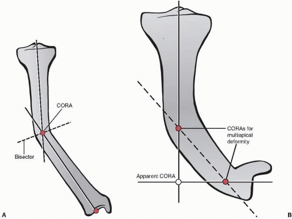
The angle formed by the two axes at the CORA is a measure of angular
deformity in that plane. Either the anatomic or mechanical axes may be
used to identify the CORA, but these axes cannot be mixed. For
diaphyseal malunions, the anatomic axes are most convenient. For
juxta-articular (metaphyseal, epiphyseal) deformities, the axis line of
the short segment is constructed using one of the three methods
described above.
the bone are identified, and then the orientations of the proximal and
distal joints are assessed. If the intersection of the proximal and
distal axes lies at the point of obvious deformity in the bone and the
joint orientations are normal, the intersection point is the CORA and
the deformity is uniapical (in the respective plane). If their
intersection lies outside the point of obvious deformity or either
joint orientation is abnormal, either a second CORA exists in that
plane and the deformity is multiapical or a translational deformity
exists in that plane, which is usually obvious on the radiograph.
angular deformities. Correction of angulation by rotating the bone
around a point on the line that bisects the angle of the CORA (the
“bisector”) ensures realignment of the anatomic and mechanical axes
without introducing an iatrogenic translational deformity.34 The bisector is a line that passes through the CORA and bisects the angle formed by the proximal and distal axes (see Fig. 26-8).72
Angular correction along the bisector results in complete deformity
correction without the introduction of a translational deformity.10,73,75,77,78
All points that lie on the bisector can be considered to be CORAs
because angulation about these points will result in realignment of the
deformed bone (see “Treatment—Osteotomies”).
the femur normally lies outside the bone, so the CORA identified using
the mechanical axis of the femur may lie outside the bone as well. By
contrast, if the CORA identified using the anatomic axis of the femur
or either axis of the tibia lies outside the bone, then a multiapical
deformity exists (see Fig. 26-8).
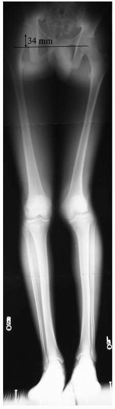
overdistraction and are characterized by their direction and magnitude.
They are measured from joint center to joint center in centimeters on
plain radiographs and compared to the contralateral normal extremity,
using an x-ray marker to correct for magnification (Fig. 26-9).91
Shortening after an injury may result from bone loss (from the injury
or débridement) or overriding of the healed fracture fragments.
Overdistraction at the time of fracture fixation may result in a healed
fracture with overlengthening of the bone.
their magnitude and the direction of the apex of angulation. Angulation
deformity of the diaphysis is often associated with limb malalignment
(MAD), as described above. Angulation deformities of the metaphysis and
epiphysis (juxta-articular deformities) can be difficult to
characterize. In particular, the angle formed by the intersection of a
joint orientation line and the anatomic or mechanical axis of the
deformed bone should be measured. When the angle formed differs
markedly from the contralateral normal limb (or normal values when the
contralateral limb is abnormal), a juxta-articular deformity is present.10,75,78 The identification of the CORA is key in characterizing angular deformities and planning their correction.
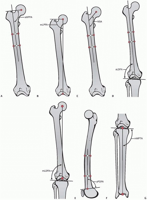 |
|
FIGURE 26-7 Joint orientation angles. A. Anatomic medial proximal femoral angle. B. Mechanical lateral proximal femoral angle. C. Neck shaft angle. D. Anatomic lateral distal femoral angle. E. Mechanical lateral distal femoral angle. F. Anatomic posterior distal femoral angle. G. Mechanical medial proximal tibial angle. (continued)
|
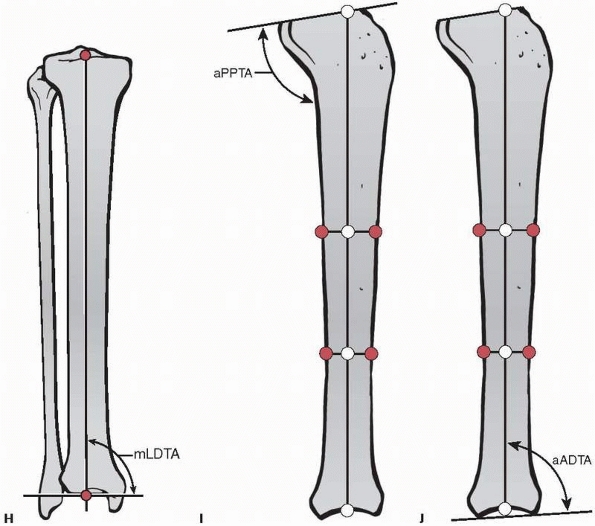 |
|
FIGURE 26-7 (continued) H. Mechanical lateral distal tibial angle. I. Anatomic posterior proximal tibial angle. J. Anatomic anterior distal tibial angle.
|
 |
|
FIGURE 26-8 A. CORA and bisector for a varus angulation deformity of the tibia. B. Multiapical tibial deformity showing that the apparent CORA joining the proximal and distal anatomic axes (solid lines) lies outside of the bone. A third anatomic axis for the middle segment (dashed line) shows two CORAs for this multiapical deformity that both lie within the bone.
|
 |
|
FIGURE 26-9 Bilateral standing 51-inch AP alignment radiograph reveals a 34-mm leg length inequality.
|
characterize; the angular deformity appears only on the AP or lateral
radiograph, respectively. If, however, the AP and lateral radiographs
both appear to have angulation with CORAs at the same level on both
views, the orientation of the angulation deformity is in an oblique
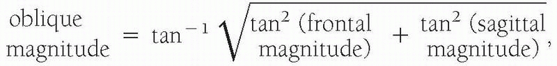
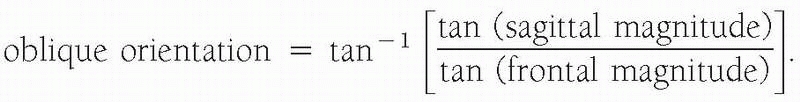
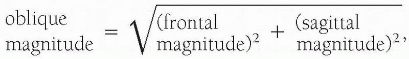
plane (Fig. 26-10). Characterization of the
magnitude and direction of oblique plane deformities can be computed
from the AP and lateral x-ray measures using either the trigonometric
or graphic method.18,37,72 Using the trigonometric method, the magnitude of an oblique plane angular deformity is
 |
|
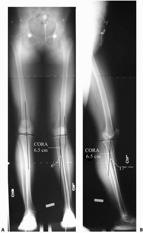
FIGURE 26-10 A 28-year-old woman presented with complaints of her leg “going out” and her knee hyperextending. A.
51-inch AP alignment radiograph reveals a 6-degree apex medial deformity with the CORA 6.5 cm distal to the proximal tibial joint orientation line. B. The lateral alignment radiograph shows a 17-degree apex posterior angulation with a CORA 6.5 cm distal to the proximal tibial joint orientation line. This patient has an oblique plane angular deformity without translation. |
approximates the exact trigonometric method. The error of approximation
for angular deformities using the graphic method is less than 4 degrees
unless the frontal and sagittal plane magnitudes are both greater than
45 degrees.10,46,72,75,77,78
AP and lateral radiographs, a translational deformity is present in
addition to an angulation deformity (Fig. 26-11).
more than one CORA on either the AP or lateral radiograph (or both). In
a multiapical deformity without translation, one of the joints will
appear maloriented relative to the anatomic axis of the respective
segment. For multiapical deformity, the anatomic
axis
of the segment that has the joint malorientation provides a third line
that crosses both of the existing lines. These intersections are the
sites of the multiple CORAs (see Fig. 26-8B).
 |
|
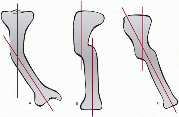
FIGURE 26-11 A. Frontal and B.
sagittal views of a tibia with an angulation-translational deformity. Note that the angulation deformity is evident only on the frontal view and the translational deformity is evident only on the sagittal view. C. The oblique view showing both deformities. |
axis of the bone. Rotational deformities are described in terms of
their magnitude and the position (internal or external rotation) of the
distal segment relative to the proximal segment. Identification of a
rotational deformity and quantification of the magnitude can be done
using clinical measurements,101 axial computed tomography (Fig. 26-12),12 or AP and lateral radiographs with either trigonometric calculation or graphical approximation.72
While axial computed tomography and radiographic methods allow for more
precise measurement of rotational deformities, clinical examination
often results in measures of sufficient accuracy to allow for adequate
correction.101
examination, the position of the foot axis, as indicated by a line
running from the second toe through the center of the calcaneus, is
compared to the projection of either the femoral or the tibial anatomic
axis. To use the femoral axis, the patient is positioned prone or sits
with the knee flexed to 90 degrees. The examiner measures the deviation
of the foot axis from the line of the femoral axis; any deviation is
considered to represent tibial malrotation. To use the tibial axis, the
patient stands with the patella facing anteriorly (i.e., aligned in the
frontal plane). To measure tibial malrotation, the examiner measures
the deviation of the foot axis from the anterior projection of the
tibial anatomic axis in the sagittal plane; any deviation of the foot
axis from the tibial anatomic axis is considered to represent tibial
malrotation.
examination, the patient is positioned prone with the knee flexed to 90
degrees and the femoral condyles parallel to the examination table. The
femur is passively rotated internally and externally by the examiner,
and the respective angular excursions of the tibia are measured.
Asymmetry of rotation in comparison to the opposite side indicates a
femoral rotational deformity. If the patient also has a tibial
angulation deformity, the tibia will not be perpendicular to the
examination table when the femoral condyles are so positioned; tibial
angulation deformity will cause an apparent asymmetry in femoral
rotation. In this case, the rotational excursions of the tibia must be
adjusted for the magnitude of the tibial angular deformity to avoid an
incorrect assessment of femoral rotation.
following either a fracture or an osteotomy. Translational deformities
are characterized by their plane, direction, magnitude, and level. The
direction of translational deformities is described in terms of the
position of the distal segment relative to the proximal segment
(medial, lateral, anterior, posterior), except for the femoral and
humeral heads where the description is the position of the head
relative to the shaft. Translational deformities may occur in an
oblique plane, and trigonometric or graphical methods similar to those
described for characterizing angulation deformities may be used to
identify the plane and direction of the deformity.18,37,72
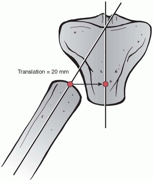
Magnitude of translation is measured as the horizontal distance from
the proximal segment’s anatomic axis to the distal segment’s anatomic
axis at the level of the proximal end of the distal segment (Fig. 26-13).
evaluation, the deformity is characterized by its type (length,
angulation, rotational, translational, or combined), the direction of
the apex (anterior, lateral, posterolateral, etc.), the orientation
plane, its magnitude, and the level of the CORA.
 |
|
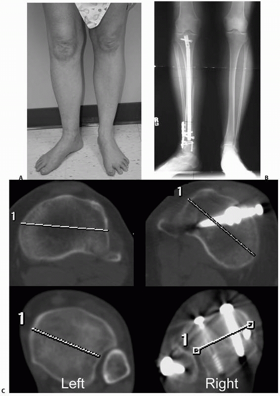
FIGURE 26-12 A.
Clinical photograph of a 38-year-old woman who presented 9 months after nail fixation of a tibial fracture. She complained of her right foot “pointing outward.” B. Plain radiographs show what appears to be a healed fracture following tibial nailing. Comparison of the proximal and distal tibias bilaterally was consistent with malrotation of the right distal tibia. C. Computed tomography scans of both proximal and distal tibias show asymmetric external rotation of the right distal tibia that measures 42 degrees. The computed tomography scan also confirmed solid bony union at the fracture site. |
 |
|
FIGURE 26-13
Method for measuring the magnitude of translational deformities. In this example, with both angulation and translation, the magnitude of the translational deformity is the horizontal distance from the proximal segment’s anatomic axis to the distal segment’s anatomic axis at the level of the proximal end of the distal segment. |
treatment of a bony deformity. Preoperative planning should include an
evaluation of overlying soft tissue free flaps and skin grafts. In
addition, scarring, tethering of neurovascular bundles, and infection
may require modifications to the treatment plan in order to address
these concomitant conditions in addition to correcting the malunion.
Furthermore, if neurovascular structures lie on the concave side of an
angular deformity, acute correction may lead to a traction injury to
them with temporary or permanent complications. In such cases, gradual
deformity correction may be preferable and allow for gradual
accommodation of the nerves or vasculature and thus avoid complications.
segments to allow realignment of the anatomic and mechanical axes. The
ability of an osteotomy to restore alignment depends on the location of
the CORA, the axis about which correction is performed (the correction
axis), and the location of the osteotomy. While the CORA is defined by
the type, direction, and magnitude of the deformity, the correction
axis depends on the location and type of the osteotomy, the soft
tissues, and the choice of fixation technique. The relation of these
three factors to one another determines the final position of the bone
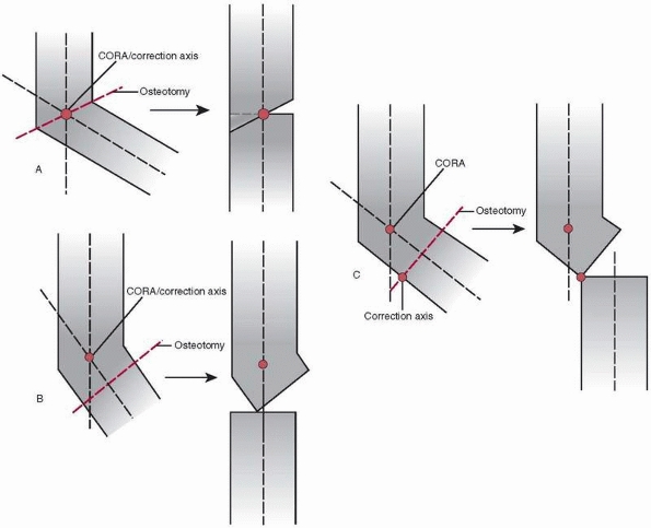
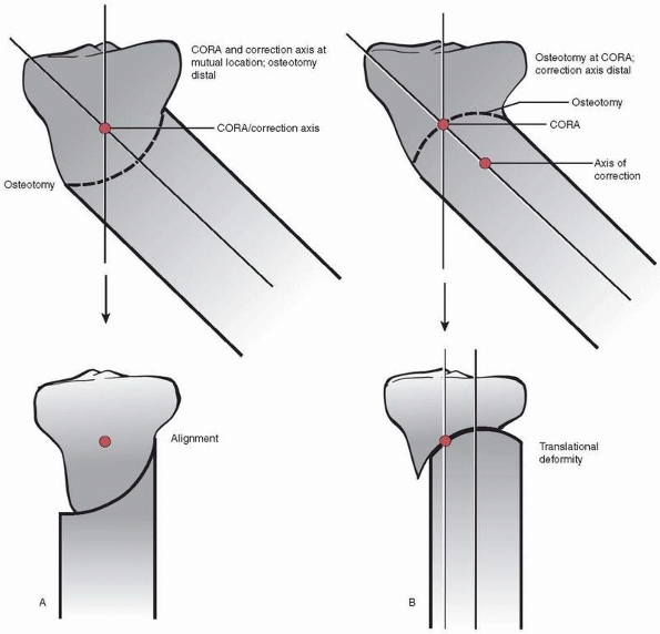
segments. Reduction following osteotomy produces one of three possible
results: (i) realignment through angulation alone; (ii) realignment
through angulation and translation; and (iii) realignment through
angulation and translation with an iatrogenic residual translational
abnormality (Fig. 26-14).
same location, the bone will realign through angulation alone, without
translation. When the CORA and correction axis are at the same location
but the osteotomy is made proximal or distal to that location, the bone
will realign through both angulation and translation. When the CORA is
at a location different than the correction axis and osteotomy,
correction of angulation aligns the proximal and distal axes in
parallel but excess translation occurs and results in an iatrogenic
translational deformity (see Fig. 26-14).
[understand that these osteotomies are not truly shaped like a dome,
they are cylindrical]) and type (opening, closing, neutral). A straight
cut, such as a transverse or wedge osteotomy, is made such that the
opposing bone ends have flat surfaces. A dome osteotomy is made such
that the opposing bone ends have congruent convex and concave
cylindrical surfaces. The type describes the rotation of the bone
segments relative to one another at the osteotomy site.
magnitude, and direction of deformity, the proximity of the deformity
to a joint, the location and its effect on the soft tissues, and the
type of fixation selected. In certain cases, a small iatrogenic
deformity may be acceptable if it is expected to have no effect on the
patient’s final functional outcome. This situation may be preferable to
attempting an unfamiliar fixation method or using a fixation technique
that the patient may tolerate poorly.
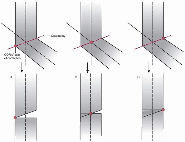
location of the osteotomy relative to the locations of the CORA and the
correction axis. When the CORA and correction axis are in the same
location (to avoid translational deformity), they may lie on the cortex
on the convex side of the deformity, on the cortex on the concave side
of the deformity, or in the middle of the bone (Fig. 26-15).
cortex of the deformity, the correction will result in an opening wedge
osteotomy (see Fig. 26-15). In an opening
wedge osteotomy, the cortex on the concave side of the deformity is
distracted to restore alignment, opening an empty wedge that traverses
the diameter of the bone. An opening wedge osteotomy also increases
bone length.
the bone, the correction distracts the concave side cortex and
compresses the convex side cortex. A bone wedge is removed from only
the convex side to allow realignment. This neutral wedge osteotomy (see
Fig. 26-15) has no effect on bone length.
cortex of the deformity, the correction will result in a closing wedge
osteotomy (see Fig. 26-15). In a closing wedge
osteotomy, the cortex on the convex side of the deformity is compressed
to restore alignment; this requires removal of a bone wedge across the
entire bone diameter. A closing wedge osteotomy also decreases bone
length (resulting in shortening).
osteotomy is located proximal or distal to the mutual site of the CORA
and correction axis. As stated above, realignment in these
cases
occurs via angulation and translation. When the CORA and correction
axis are not at the same point and the osteotomy is proximal or distal
to the CORA, the correction maneuver results in excess translation and
an iatrogenic translational deformity.
 |
|
FIGURE 26-14 Possible results when using osteotomy for correction of deformity. A.
The CORA, the correction axis, and the osteotomy all lie at the same location; the bone realigns through angulation alone, without translation. B. The CORA and the correction axis lie in the same location, but the osteotomy is proximal or distal to that location; the bone realigns through both angulation and translation. C. The CORA lies at one location and the correction axis and the osteotomy lie in a different location; correction of angulation results in an iatrogenic translational deformity. |
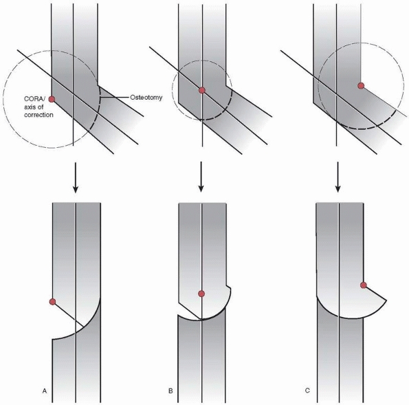
location of the CORA and the correction axis relative to the osteotomy.
In contrast to a wedge osteotomy, however, the osteotomy site can never
pass through the mutual CORA-correction axis (Fig. 26-16). Thus, translation will always occur with deformity correction using a dome osteotomy.
located such that the angulation and obligatory translation that occurs
at the osteotomy site results in realignment. Attempts at realignment
when the CORA and correction axis are not mutually located results in a
translational deformity (see Fig. 26-16).
Similar to wedge osteotomy, the CORA and correction axis may lie on the
cortex on the convex side of the deformity, on the cortex on the
concave side of the deformity, or in the middle of the bone.
for dome osteotomies. When the CORA and correction axis lie on the
convex cortex of the deformity, the correction will result in an
opening dome osteotomy (Fig. 26-17). The
translation that occurs in an opening dome osteotomy increases final
bone length. When the CORA and correction axis lie in the middle of the
bone, the correction will result in a neutral dome osteotomy. A neutral
dome osteotomy has no effect on bone length. When the CORA and
correction axis lie on the concave cortex of the deformity, the
correction will result in a closing dome osteotomy. The translation
that occurs in a closing dome osteotomy decreases final bone length.
Unlike wedge osteotomies, the movement of one bone segment on the other
is rarely impeded, so removal of bone is not typically required unless
the final
configuration results in significant overhang of the bone beyond the aligned bone column.
 |
|
FIGURE 26-15 Wedge osteotomies; the osteotomy is made at the level of the CORA and correction axis in all of these examples. A.
Opening wedge osteotomy. The CORA and correction axis lie on the cortex on the convex side of the deformity. The cortex on the concave side of the deformity is distracted to restore alignment, opening an empty wedge that traverses the diameter of the bone. Opening wedge osteotomy increases final bone length. B. Neutral wedge osteotomy. The CORA and correction axis lie in the middle of the bone. The concave side cortex is distracted and the convex side cortex is compressed. A bone wedge is removed from the convex side. Neutral wedge osteotomy has no effect on final bone length. C. Closing wedge osteotomy. The CORA and correction axis lie on the concave cortex of the deformity. The cortex on the convex side of the deformity is compressed to restore alignment, requiring removal of a bone wedge across the entire bone diameter. A closing wedge osteotomy decreases final bone length. |
immediate correction of limb length by acute lengthening with bone
grafting or acute shortening, respectively. The extent of acute
lengthening or shortening that is possible is limited by the soft
tissues (soft tissue compliance, surgical and open wounds, and
neurovascular structures).
the bone ends to the appropriate length, applying a bone graft, and
stabilizing the construct to allow incorporation of the graft. Options
for treating length deformities include the use of: (i) autogenous
cancellous or cortical bone grafts; (ii) vascularized autografts; (iii)
bulk or strut cortical allografts; (iv) mesh cagebone graft constructs;
and (v) synostosis techniques. A variety of internal and external
fixation treatment methods may be used to stabilize the construct
during graft incorporation.9 The amount of shortening that requires lengthening correction is uncertain.38,65,102
In the upper extremity, up to 3 to 4 cm of shortening is generally well
tolerated, and restoring length when shortening exceeds this value have
been reported to improve function.1,19,59,71,81,96,104,107
In the lower extremity, up to 2 cm of shortening may be treated with a
shoe lift; tolerance for a 2 to 4 cm shoe lift is poor for most
patients, and most patients with shortening of greater than 4 cm will
benefit from restoration of length.7,8,31,64,102,109
overdistraction by first resecting the appropriate length of bone and
then stabilizing the approximated bone ends under compression. For the
paired bones of the forearm and leg, the unaffected bone
requires
partial excision to allow shortening and compression of the affected
bone. For example, partial excision of the intact fibula is necessary
to allow shortening and compression of the tibia.
 |
|
FIGURE 26-16
In a dome osteotomy, the osteotomy site cannot pass through both the CORA and the correction axis. Thus, translation will always occur when using a dome osteotomy. A. Ideally, the CORA and correction axis are mutually located with the osteotomy proximal or distal to that location such that the angulation and obligatory translation that occurs at the osteotomy site results in realignment of the bone axis. B. When the CORA and correction axis are not mutually located, a dome osteotomy through the CORA location results in a translational deformity. |
The most common form of gradual correction is gradual distraction to
correct limb shortening. Gradual correction methods for length
deformities can also be used to correct associated angular,
translational, or rotational deformities simultaneously while restoring
length.
corticotomy (usually metaphyseal) and distraction of the bone segments
at a rate of 1 mm per day using a rhythm of 0.25 mm of distraction
repeated four times per day. The bone formed at the distraction site is
formed through the process of distraction osteogenesis, as discussed
below in the “Ilizarov Techniques” section.
fixation during healing. The correction may be made acutely and then
stabilized using a number of internal or external fixation methods.28,39
Alternatively, the correction may be made gradually using external
fixation to both restore alignment and provide stabilization during
healing.28,105
 |
|
FIGURE 26-17
Dome osteotomies; the CORA and correction axis are mutually located with the osteotomy distal to that location in all of these examples. A. Opening dome osteotomy. The CORA and correction axis lie on the cortex on the convex side of the deformity. Opening dome osteotomy increases final bone length. B. Neutral dome osteotomy. The CORA and correction axis lie in the middle of the bone. Neutral dome osteotomy has no effect on final bone length. C. Closing dome osteotomy. The CORA and correction axis lie on the concave cortex of the deformity. A closing dome osteotomy decreases final bone length and can result in significant overhang of bone that may require resection. |
amenable to correction using a wedge osteotomy at the same level as the
correction axis and the CORA. For juxta-articular angulation
deformities, however, the correction axis and the CORA may be located
too close to the respective joint to permit a wedge osteotomy. Thus,
juxta-articular angulation deformities may require a dome osteotomy
with location of the osteotomy proximal or distal to the level of the
correction axis and the CORA.
osteotomy and rotational realignment followed by stabilization.
Stabilization may be accomplished using internal or external fixation
following acute correction, or external fixation may be used to
gradually correct the deformity. The level for the osteotomy, however,
can
be difficult to determine. While the level of the deformity is obvious
in the case of an angulated malunion, the level of deformity in
rotational limb deformities is often difficult to determine.
Consequently, other factors, including muscle and tendon line of pull,
neurovascular structures, and soft tissues, are usually considered to
determine the level of deformity and level of osteotomy for correction
of a rotational deformity.32,56,57,72,80,100
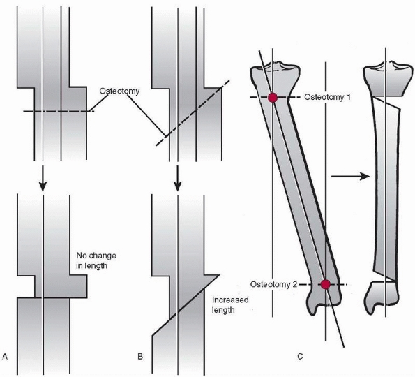
three ways. First, a single transverse osteotomy may be made to restore
alignment through pure translation without angulation; the transverse
osteotomy does not have to be made at the level of the deformity (Fig. 26-18).
Second, a single oblique osteotomy may be made at the level of the
deformity to restore alignment and gain length. Third, a translational
deformity can be represented as two angulations with identical
magnitudes but opposite directions. Therefore, two wedge osteotomies at
the level of the respective CORAs and angular corrections of equal
magnitudes in opposite directions may be used to correct a
translational deformity. It should be noted that the osteotomy types
used in this third method (opening, closing, or neutral) will affect
final bone length. Internal or external fixation may be used to provide
stabilization following acute correction of translational deformities,
or gradual correction may be carried out using external fixation.
 |
|
FIGURE 26-18 A. A single transverse osteotomy to restore alignment through pure translation without angulation. B. A single oblique osteotomy at the level of the deformity to restore alignment and gain length. C.
A translational deformity represented as two angulations with identical magnitudes but opposite directions causing malalignment of the mechanical axis of the lower extremity. Two wedge osteotomies of equal magnitudes in opposite directions at the levels of the respective CORAs may be used to correct a translational deformity and restore alignment of the mechanical axis of the lower extremity. |
Treatment planning begins with identifying and characterizing each
deformity independent from the other deformities. Once all deformities
have been characterized, they are assessed to determine which require
correction to restore function. Correction of all of the deformities
may be unnecessary; for example, small translational deformities or
angulation deformities in the sagittal plane may not interfere with
limb function and may remain untreated. Once those deformities
requiring correction are identified, the treatment plan outlines the
order and method of correction for each deformity.
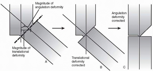
correct two deformities. For example, a combined
angulation-translational deformity can be corrected using a single
osteotomy at
the
level of the apex of the angulation deformity. This method restores
alignment and congruency of the medullary canals and cortices of the
respective bone segments (Fig. 26-19).
The deformities are then reduced one at a time—reducing translation and
then angulation, for instance. Consequently, stabilization can be
achieved using an intramedullary nail, as well as a number of other
internal fixation and external fixation methods.
 |
|
FIGURE 26-19 A single osteotomy to correct an angulation-translational deformity. A. A single osteotomy is made to allow correction of both deformities. B. Correction of the translational deformity, followed by C. correction of the angulation deformity, resulting in realignment.
|
treated as multiapical angulation deformities with an osteotomy through
either or both CORAs in the frontal and sagittal planes. While this
method restores alignment of the bone’s mechanical axis, it can also
result in incomplete bone-to-bone contact and incongruence of the bone
segments’ medullary canals and cortices. As a result, stabilization
cannot be achieved using an intramedullary nail and other internal
fixation and external fixation methods are required to stabilize the
bone segments.
 |
|
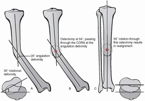
FIGURE 26-20 A.
Combined angulation-rotational deformity with a 20-degree angulation deformity and a 30-degree rotational deformity. Calculations of the correction axis (see text for formula) show an inclination of 56 degrees, which corresponds to an osteotomy inclination of 34 degrees. B. The 34-degree osteotomy is made such that it passes through the CORA of the angulation deformity. C. Rotation of 36 degrees about the correction axis in the plane of the osteotomy results in realignment by simultaneous correction of both deformities. |
corrected by a single rotation of the distal segment around an oblique
axis that represents the resolutions of both the component angulation
axis and rotation axis (Fig. 26-20).66 The direction
and magnitude of the combined angulation-rotational deformity are both
characterized in this oblique axis. The angle of the oblique correction
axis, which is perpendicular to the plane of the necessary osteotomy,
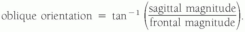
can be approximated using trigonometry (axis angle = arctan
[rotation/angulation]; orientation of plane of osteotomy = 90- axis
angle).
passes through the level of the CORA of the angulation deformity (i.e.,
the bisector of the axes of the proximal and distal segments). Rotation
of the distal segment about this CORA in the plane of the osteotomy
results in realignment; opening and closing wedge corrections can also
be achieved by using the CORA located on the respective cortex.
Rotation of the distal segment in the plane of the osteotomy but not
about a CORA will lead to a secondary translational deformity. This
secondary deformity can be corrected by reducing the translation after
rotation is completed. Locating the level of the osteotomy distal to
the level of the CORA and correcting the secondary translational
deformity can be used to correct a combined deformity if locating the
osteotomy at the level of the CORA is impractical, such as would occur
if the osteotomy would violate a growth plate or place soft tissues or
neurovascular structures at risk.
regions (e.g., epiphysis, metaphysis, diaphysis) define the anatomic
location. While a bone-by-bone discussion is beyond the scope of this
chapter, we will address the influence of anatomic region on the
treatment of malunions in general terms.
in the central section of long bones. Characterizing deformities is
straightforward, as angulation and translational deformities are
usually obvious on plain radiographs. In addition, the use of wedge
osteotomies through the CORA for deformity correction is generally
achievable, thus allowing reduction of the deformity without concerns
about inducing secondary translational deformities. By virtue of their
relatively homogenous morphology, diaphyseal deformities are amenable
to a wide array of fixation methods following correction.
Intramedullary nail fixation is preferable when practical (Fig. 26-21).
 |
|
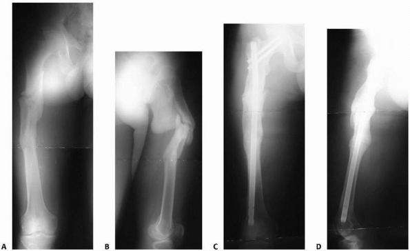
FIGURE 26-21 A,B. AP and lateral radiographs on presentation. C,D. AP and lateral radiographs following deformity correction with closed antegrade femoral nailing.
|
epiphysis are more difficult to identify, characterize, and treat. In
addition to the juxta-articular deformities of length, angulation,
rotation, and translation and the presence of joint malorientation,
there may also be malreduction of articular surfaces and compensatory
joint deformities, such as soft tissue contractures and fixed joint
subluxation or dislocation. Identification, characterization, and
prioritization of each component of the deformity are critical to
forming a successful treatment plan.
often accomplished using plate and screw fixation or external fixation.
Gradual correction may be accomplished using external fixation (Fig. 26-22).
rigidity of fixation, versatility for various anatomic locations and
situations (e.g., periarticular deformities), correction of deformities
under direct visualization, and safety following failed or temporary
external fixation. Disadvantages of the method include extensive soft
tissue dissection, limitation of early weight bearing and
function,
and inability to correct significant shortening deformity. A variety of
plate types and techniques is available, and these are presented in the
chapters covering specific fracture types. In cases of deformity
correction with poor bone-to-bone contact following reduction, however,
other methods of skeletal stabilization should be considered.
 |
|
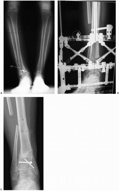
FIGURE 26-22 A.
Presenting AP radiograph of a 45-year-old woman with a malunited distal tibial fracture. This pure frontal plane deformity measured 21 degrees of varus with a CORA located 21 mm proximal to the distal tibial joint orientation line. B. AP radiograph following transverse osteotomy during gradual deformity correction (differential lengthening) using a Taylor Spatial Frame. C. Final AP radiograph following deformity correction and bony consolidation. |
 |
|
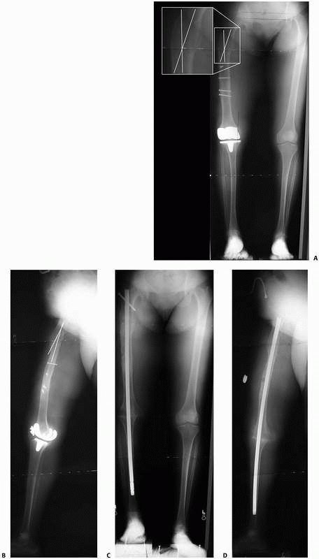
FIGURE 26-23 A,B.
AP and lateral 51-inch alignment radiographs of a 52-year-old woman with a painful total knee arthroplasty. This patient had severe arthrofibrosis, severe pain, and had failed revision total knee arthroplasty. She was referred for a knee fusion but was noted to have an oblique plane angular malunion of her proximal femur from a prior fracture, as indicated by the white lines superimposed on the femur. It was felt that without correction of this femoral malunion, passage of the knee fusion nail through the angled femoral diaphysis would have been difficult, and the final clinical and functional results would likely have been suboptimal due to malalignment of the mechanical axis of the lower extremity. C,D. Follow-up radiographs 5 months after operative treatment with resection of the total knee arthroplasty, percutaneous corticotomy of the proximal femur to correct the deformity, and percutaneous antegrade femoral nailing to stabilize the corticotomy site and stabilize the knee fusion site. |
 |
|
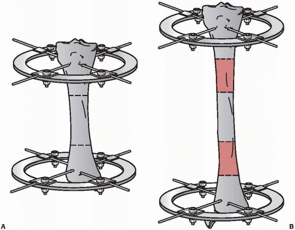
FIGURE 26-24 Bifocal lengthening. A. Tibia with length deformity showing two corticotomy sites. B. Tibia following distraction osteogenesis at both corticotomy sites showing restoration of length.
|
threaded holes on the corresponding plate. This locking effect creates
a fixed-angle device, or “single-beam” construct, because no motion
occurs between the screws and the plate.15,24,42
In contrast to traditional plate-and-screw constructs, the locked
screws resist bending moments and the construct distributes axial load
across all of the screw-bone interfaces.24,42
As compared to compression plating where healing is by direct osteonal
bridging, locked plating performed without compression results in
healing via callus formation.24,48,79,95,110
Due to the inherent axial and rotational stability with locked devices,
obtaining contact between the plate and the bone is not necessary; the
construct can be thought of as an external fixator placed within the
body. Consequently, periosteal damage and microvascular compromise are
minimal. Locking plates are considerably more expensive than
traditional plates and should be used in deformity cases that are not
amenable to traditional plate-and-screw fixation.15
the lower extremity because of the strength and load-sharing
characteristics of intramedullary nails. This method of fixation is
ideal for cases where diaphyseal deformities are being corrected (Fig. 26-23).
The method may also be useful for deformities at the
metaphyseal-diaphyseal junction. Intramedullary implants are excellent
for osteopenic bone where screw purchase may be poor.
including that they: (i) are primarily percutaneous, minimally
invasive, and typically requires only minimal soft tissue dissection;
(ii) can promote the generation of osseous tissue; (iii) are versatile;
(iv) can be used in the presence of acute or chronic infection; (v)
allow for stabilization of small intra-articular or periarticular bone
fragments; (vi) allow simultaneous deformity correction and enhancement
of bone healing;3,4,5,9,13,36,54,55
(vii) allow immediate weight bearing and early joint function; (viii)
allow augmentation or modification of the treatment as needed through
frame adjustment; and (ix) resist shear and rotational forces while the
tensioned wires allow the “trampoline effect” (axial loadingunloading)
during weight-bearing activities.
stabilize virtually any type of deformity, including complex combined
deformities, and restore limb length in cases of limb foreshortening. A
variety of treatment modes can be employed using the Ilizarov external
fixator, including distraction-lengthening, and multiple sites in a
single bone can be treated simultaneously. Monofocal lengthening
involves a single site undergoing distraction. Bifocal lengthening
denotes that two lengthening sites exist (Fig. 26-24).
corticotomy site in distraction-lengthening Ilizarov treatment occurs
by distraction
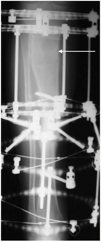
osteogenesis (Fig. 26-25).5,6,20,50,67
Distraction produces a tension-stress effect that causes neovascularity
and cellular proliferation in many tissues, including bone regeneration
primarily through intramembranous bone formation. Corticotomy and
distraction osteogenesis result in profound biological stimulation,
similar to bone grafting. For example, Aronson4
reported a nearly ten-fold increase in blood flow following corticotomy
and lengthening at the proximal tibia distraction site relative to the
control limb in dogs as well as increased blood flow in the distal
tibia.
 |
|
FIGURE 26-25 Regenerate bone (arrow) at the corticotomy site is formed via distraction osteogenesis.
|
 |
|
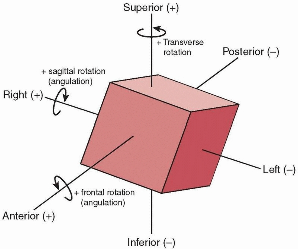
FIGURE 26-26 Definitions used to characterize complex deformities using three angular rotations and three linear displacements.
|
distraction osteogenesis. First, the corticotomy or osteotomy must be
performed using a low-energy technique to minimize necrosis. Second,
distraction of the metaphyseal or metaphyseal-diaphyseal regions has
superior potential for regenerate bone formation relative to diaphyseal
sites. Third, the external fixator construct must be very stable.
Fourth, a latency period of 7 to 14 days following the corticotomy and
prior to beginning distraction is recommended. Fifth, since the
formation of the bony regenerate is slower in some patients, the
treating physician should monitor the progression of the regenerate on
plain radiographs and adjust the rate and rhythm of distraction
accordingly. Sixth, a consolidation phase in which external fixation
continues in a static mode following restoration of length that
generally lasts 2 to 3 times as long as the distraction phase is
required to allow maturation and hypertrophy of the regenerate.
be characterized by describing the position of one bone segment
relative to another in terms of angular rotations in each of three
planes and linear displacements in each of three axes. Using the
methods described above, complex deformities can be characterized using
magnitudes for each of these six parameters. Directions of the
rotations or displacements are defined as positive and negative
relative to the anatomic position. Anterior, right, and superior
displacements are defined as positive values. Positive rotation is
defined by the right-hand rule: with the thumb pointed in the positive
direction along the respective axis (defined identically to the
displacement descriptions), the curled fingers indicate the direction
of positive rotation (Fig. 26-26). For example,
angulation in the frontal plane is rotation about an AP axis. With
anterior defined as the positive direction for this axis,
counterclockwise rotation (to an examiner who is face to face with the
patient) is positive and clockwise rotation is negative.
 |
|
FIGURE 26-27 A.
Taylor Spatial Frame with rings placed obliquely to one another and in parallel with the position of the tibial angular-translation deformity. B. Taylor Spatial Frame following correction of the deformity by adjusting the six struts to attain neutral frame height (i.e., rings in parallel). |
correction to allow adaptation of not only the bone but also
surrounding soft tissues and neurovascular structures. The modern
Ilizarov hardware system uses different components (hinges, threaded
rods, rotation-translation boxes) to achieve correction of multiple
deformity types in a single bone. Alternatively, the Taylor Spatial
Frame (Fig. 26-27), which uses six telescopic struts, can be used to correct complex combined deformities.2,25,26,27,29,58,62,63,68,69,83,84,85,86,87,97,98,103,106,108,111,112
A computer program is used in treatment planning to determine strut
lengths for the original frame construction. The rings of the external
fixator frame are attached perpendicular to the respective bone
segments and the struts are gradually adjusted to attain neutral frame
height (i.e., rings in parallel). Any residual deformity is then
corrected by further adjusting the struts.
are corrected at the same time, or sequential, in which some
deformities (e.g., angulation-rotation) are corrected before others
(e.g., translations). The rate at which correction occurs must be
determined on a patient-by-patient basis and depends on the type and
magnitude of deformity, the potential effects on the soft tissues, the
health and healing potential of the patient, and the balance between
premature consolidation and inadequate regenerate formation.
M, Shirai H, Okamoto M, Onomura T. Lengthening of the forearm by callus
distraction. J Hand Surg [Br] 1996 Apr;21(2):151-163.
MJ. Taylor Spatial Frame in the treatment of pediatric and adolescent
tibial shaft fractures. J Pediatr Orthop 2006;26(2):164-170.
J. Limb-lengthening, skeletal reconstruction, and bone transport with
the Ilizarov method. J Bone Joint Surg 1997;79(8):1243-1258.
J, Good B, Stewart C, et al. Preliminary studies of mineralization
during distraction osteogenesis. Clin Orthop Relat Res 1990;250:43-49.
J, Harrison B, Boyd CM, et al. Mechanical induction of osteogenesis:
preliminary studies. Ann Clin Lab Sci 1988;18(3):195-203.
A, Paley D, Herzenberg JE. Improvement in gait parameters after
lengthening for the treatment of limb-length discrepancy. J Bone Joint
Surg 1999 Apr;81(4):529-534.
RJ, Dean JB, Skinner TM, et al. Limb length inequality: clinical
implications for assessment and intervention. J Orthop Sports Phys Ther
2003;33(5):221-234.
MR. Nonunions: evaluation and treatment. In: Browner BD, Levine AM,
Jupiter JB, et al, eds. Skeletal Trauma: Basic Science, Management, and
Reconstruction. 3rd ed. Philadelphia: W.B. Saunders, 2003:507-604.
MR, Gugenheim JJ. The treatment of complex traumatic problems of the
forearm using Ilizarov external fixation. Atlas of the Hand Clinics
2000;5(1):103-116.
MR, Gugenheim JJ, O’Connor DP, et al. Ilizarov correction of malrotated
femoral shaft fracture initially treated with an intramedullary nail: a
case report. Am J Orthop 2004;33(10):489-493.
MR, O’Connor DP. Basic sciences. In: Miller MD, ed. Review of
Orthopaedics. 4th ed. Philadelphia: W.B. Saunders, 2004:1-153.
MR, O’Connor DP. Ilizarov compression over a nail for aseptic femoral
nonunions that have failed exchange nailing: a report of five cases. J
Orthop Trauma 2003; 17(10):668-676.
R, Catagni M, Johnson EE. The treatment of infected nonunions and
segmental defects of the tibia by the methods of Ilizarov. Clin Orthop
Relat Res 1992;280: 143-152.
JD, Justin D, Kasparis T, et al The intramedullary skeletal kinetic
distractor (ISKD): first clinical results of a new intramedullary nail
for lengthening of the femur and tibia. Injury 2001;32(Suppl
4):SD129-139.
C, Delefortrie G, Coutelier L, et al. Bone regenerate formation in
cortical bone during distraction lengthening: an experimental study.
Clin Orthop Relat Res 1990; 250:34-42.
DI, Fox DB, Tomlinson JL, et al. Use of radiographic measures and
three-dimensional computed tomographic imaging in surgical correction
of an antebrachial deformity in a dog. J Am Vet Med Assoc
2008;232(1):68-73.
NA, Skie MC, Jackson WT. The treatment of tibial nonunion with angular
deformity using an Ilizarov device. J Trauma 1995;38(1):111-117.
M, Bialik V, Katzman A. Correction of deformities in children using the
Taylor spatial frame. J Pediatr Orthop B 2006 Nov;15(6):387-395.
DS, Madan SS, Koval KJ, et al. Correction of tibia vara with six-axis
deformity analysis and the Taylor Spatial Frame. J Pediatr Orthop
2003;23(3):387-391.
DS, Madan SS, Ruchelsman DE, et al. Accuracy of correction of tibia
vara: acute versus gradual correction. J Pediatr Orthop
2006;26(6):794-798.
DS, Shin SS, Madan S, et al. Correction of tibial malunion and nonunion
with six-axis analysis deformity correction using the Taylor Spatial
Frame. J Orthop Trauma 2003;17(8):549-554.
DB, Tomlinson JL, Cook JL, et al. Principles of uniapical and biapical
radial deformity correction using dome osteotomies and the center of
rotation of angulation methodology in dogs. Vet Surg 2006;35(1):67-77.
L, Widmann RF. Advances in management of limb length discrepancy and
lower limb deformity. Curr Opin Pediatr 2008;20(1):46-51.
M, Kato H, Minami A. Rotational osteotomy at the diaphysis of the
radius in the treatment of congenital radioulnar synostosis. J Pediatr
Orthop 2005;25(5): 676-679.
TN, Evans M, Simpson H, et al. Force-displacement behaviour of
biological tissue during distraction osteogenesis. Med Eng Phys
1998;20(9):708-715.
B, Heijens E, Pfeil J, et al. Calculation and correction of secondary
translation deformities and secondary length deformities. Orthopedics
2004;27(7):760-766.
SA. The Ilizarov method. In: Browner BD, Levine AM, Jupiter JB, eds.
Skeletal Trauma: Fractures, Dislocations, Ligamentous Injuries. 2nd ed.
Philadelphia: W.B. Saunders, 1998:661-701.
JJ Jr, Brinker MR. Bone realignment with use of temporary external
fixation for distal femoral valgus and varus deformities. J Bone Joint
Surg 2003;85-A(7): 1229-1237.
JJ, Probe RA, Brinker MR. The effects of femoral shaft malrotation on
lower extremity anatomy. J Orthop Trauma 2004;18(10):658-664.
JM, Javed A, Russell J, et al. Effect of the foot on the mechanical
alignment of the lower limbs. Clin Orthop Relat Res
2003;415(415):193-201.
S, Gosling T, Pape HC, et al. Limb lengthening with the Intramedullary
Skeletal Kinetic Distractor (ISKD). Operative Orthopadie und
Traumatologie 2005; 17(1):79-101.
S, Pape HC, Gosling T, et al. Improved comfort in lower limb
lengthening with the intramedullary skeletal kinetic distractor.
Principles and preliminary clinical experiences. Arch Orthop Trauma
Surg 2004;124(2):129-133.
E, Gladbach B, Pfeil J. Definition, quantification, and correction of
translation deformities using long leg, frontal plane radiography. J
Pediatr Orthop B 1999;8(4): 285-291.
RS, May RL, Crossley KM. Is there an alternative to the full-leg
radiograph for determining knee joint alignment in osteoarthritis?
Arthritis Rheum 2006;55(2): 306-313.
HP, Wildburger R, Szyszkowitz R. Observations concerning different
patterns of bone healing using the Point Contact Fixator (PC-Fix) as a
new technique for fracture fixation. Injury 2001;32(Suppl 2):B15-25.
MA, Fowler PJ, Birmingham TB, et al. Foot rotational effects on
radiographic measures of lower limb alignment. Can J Surg
2006;49(6):401-406.
GA. The tension-stress effect on the genesis and growth of tissues.
Part I. The influence of stability of fixation and soft-tissue
preservation. Clin Orthop Relat Res 1989;238:249-281.
GA. The tension-stress effect on the genesis and growth of tissues.
Part II. The influence of the rate and frequency of distraction. Clin
Orthop Relat Res 1989;239: 263-85.
GA. Transosseous Osteosynthesis. Theoretical and Clinical Aspects of
the Regeneration and Growth of Tissue. Berlin: Springer-Verlag, 1992.
GA, Kaplunov AG, Degtiarev VE, et al. Treatment of pseudarthroses and
ununited fractures, complicated by purulent infection, by the method of
compressiondistraction osteosynthesis. Ortop Travmatol Protez
1972;33(11):10-14.
M, Ferri-de Baros F, Chan G, et al. Correction of rotational deformity
of the tibia in cerebral palsy by percutaneous supramalleolar
osteotomy. J Bone Joint Surg Br 2005; 87(10):1411-1415.
WF 3rd, Staheli LT. Tibial rotational osteotomy for idiopathic torsion.
A comparison of the proximal and distal osteotomy levels. Clin Orthop
Relat Res 1992; 283(283):285-289.
LP, Steen H, Reikeras O. No difference in tibial lengthening index by
use of Taylor spatial frame or Ilizarov external fixator. Acta Orthop
2006;77(5):772-777.
N, Fixsen JA. Distraction osteogenesis in congenital limb length
discrepancy: a review. J R Coll Surg Edinb 1996;41(4):258-264.
J, Nadarajah R, Allen PW, et al. Ilizarov external fixator: acute
shortening and lengthening versus bone transport in the management of
tibial non-unions. Injury 2005;36(5):662-668.
DR, Shah S, Elliott J, et al. The Ilizarov method in nonunion,
malunion, and infection of fractures. J Bone Joint Surg Br
1997;79(2):273-279.
H, Tsuchiya H, Sakurakichi K, et al. Deformity correction and
lengthening of lower legs with an external fixator. Int Orthop
2006;30(6):550-554.
H, Tsuchiya H, Takato K, et al. Correction of ankle ankylosis with
deformity using the taylor spatial frame: a report of three cases. Foot
Ankle Int 2007;28(12): 1290-1294.
DC, Siebenrock KA, Schiele B, et al. A new methodology for the planning
of single-cut corrective osteotomies of malaligned long bones. Clin
Biomech (Bristol, Avon) 2005;20(2):223-227.
T, Ohzono K, Shimizu N, et al. Correction of severe posttraumatic
deformities in the distal femur by distraction osteogenesis using
Taylor Spatial Frame: a case report. Arch Orthop Trauma Surg
2006;126(1):66-69.
SJ, Helfet DL, Rozbruch SR. Temporary intentional leg shortening and
deformation to facilitate wound closure using the Ilizarov/Taylor
spatial frame. J Orthop Trauma 2006;20(6):419-424.
KJ, Leyes M, Forriol F, et al. Distraction osteogenesis of the lower
extremity with use of monolateral external fixation. A study of 261
femora and tibiae. J Bone Joint Surg 1998;80(6):793-806.
G, Campiglio GL, Candiani P. Bone lengthening in malformed upper limbs:
a 4-year experience. Acta Chir Plast 1994;36(1):3-6.
D, Chaudray M, Pirone AM, et al. Treatment of malunions and
malnonunions of the femur and tibia by detailed preoperative planning
and the Ilizarov techniques. Orthop Clin North Am 1990;21(4):667-691.
D, Herzenberg JE, Paremain G, et al. Femoral lengthening over an
intramedullary nail. A matched-case comparison with Ilizarov femoral
lengthening. J Bone Joint Surg 1997;79(10):1464-1480.
D, Herzenberg JE, Tetsworth K, eds. Program Manual: Annual Baltimore
Limb Deformity Course. Baltimore: Maryland Center for Limb Lengthening,
2000.
D, Herzenberg JE, Tetsworth K, et al. Deformity planning for frontal
and sagittal plane corrective osteotomies. Orthop Clin North Am
1994;25(3):425-465.
D, Tetsworth K. Mechanical axis deviation of the lower limbs.
Preoperative planning of multiapical frontal plane angular and bowing
deformities of the femur and tibia. Clin Orthop Relat Res
1992;280:65-71.
D, Tetsworth K. Mechanical axis deviation of the lower limbs.
Preoperative planning of uniapical angular deformities of the tibia or
femur. Clin Orthop Relat Res 1992; 280:48-64.
SM. Evolution of the internal fixation of long bone fractures. The
scientific basis of biological internal fixation: choosing a new
balance between stability and biology. J Bone Joint Surg Br
2002;84(8):1093-1110.
M, Trivett A, Baker R, et al. Femoral derotation osteotomy in spastic
diplegia. Proximal or distal? J Bone Joint Surg Br 2003;85(2):265-272.
RA, Skaggs DL, Rosenwasser MP, et al. Lengthening of pediatric forearm
deformities using the Ilizarov technique: functional and cosmetic
results. J Hand Surg [Am] 1999;24(2):331-338.
MA, Boyle J, Mihalko WM, et al. Reliability of measuring long-standing
lower extremity radiographs. Orthopedics 2007;30(4):299-303.
MJ, McFadyen I, Livingstone JA, et al. Computer hexapod assisted
orthopaedic surgery (CHAOS) in the correction of long bone fracture and
deformity. J Orthop Trauma 2007;21(5):337-342.
SR, Fragomen AT, Ilizarov S. Correction of tibial deformity with use of
the Ilizarov-Taylor spatial frame. J Bone Joint Surg 2006;88(Suppl
4):156-174.
SR, Helfet DL, Blyakher A. Distraction of hypertrophic nonunion of
tibia with deformity using Ilizarov/Taylor Spatial Frame. Report of two
cases. Arch Orthop Trauma Surg 2002;122(5):295-298.
SR, Pugsley JS, Fragomen AT, et al. Repair of tibial nonunions and bone
defects with the Taylor Spatial Frame. J Orthop Trauma 2008;22(2):88-95.
SR, Weitzman AM, Watson JT, et al. Simultaneous treatment of tibial
bone and soft-tissue defects with the Ilizarov method. J Orthop Trauma
2006;20(3): 197-205.
U, Pizzoli A, Minari C, et al. Alignment and articular orientation of
lower limbs: manual vs computer-aided measurements on digital
radiograms. Radiol Med (Torino) 2005;109(3):234-238.
S, Zhao C. Assessment of lower limb alignment: supine fluoroscopy
compared with a standing full-length radiograph. J Bone Joint Surg
2008;90(1):43-51.
S, Zhao C, McKeon JJ, et al. Computed radiographic measurement of
limb-length discrepancy. Full-length standing anteroposterior
radiograph compared with scanogram. J Bone Joint Surg
2006;88(10):2243-2251.
J, Scharitzer M, Peloschek P, et al. Quantification of axial alignment
of the lower extremity on conventional and digital total leg
radiographs. Eur Radiol 2005;15(1): 170-173.
C. Distraction osteogenesis of the femur using conventional monolateral
external fixator. Arch Orthop Trauma Surg 2008;128(9):889-899.
WH Jr, Froimson AI. Callotasis lengthening in the upper extremity:
indications, techniques, and pitfalls. J Hand Surg [Am]
1991;16(5):932-939.
A, Nordin L, Hill RA. Spatial frame correction of anterior growth
arrest of the proximal tibia: report of three cases. J Pediatr Orthop B
2008;17(2):61-64.
M, Pfeiffer M, Kotz R, et al. Lower limb deformities in children:
two-stage correction using the Taylor spatial frame. J Pediatr Orthop B
2003;12(2):123-128.
AV, Birmingham TB, DaSilva JJ, et al. Reliability of lower limb frontal
plane alignment measurements using plain radiographs and digitized
images. J Knee Surg 2004;17(4):203-210.
LT, Corbett M, Wyss C, et al. Lower-extremity rotational problems in
children. Normal values to guide management. J Bone Joint Surg
1985;67(1):39-47.
K, Krome J, Paley D. Lengthening and deformity correction of the upper
extremity by the Ilizarov technique. Orthop Clin North Am
1991;22(4):689-713.
KD, Paley D. Accuracy of correction of complex lower-extremity
deformities by the Ilizarov method. Clin Orthop Relat Res
1994;301(301):102-110.
E, Sarikloglou S, Papasoulis E, et al. Correction of tibial deformity
in Paget disease using the Taylor spatial frame. J Bone Joint Surg Br
2008;90(2):243-244.
A, Paley D, Catagni MA, et al. Lengthening of the forearm by the
Ilizarov technique. Clin Orthop Relat Res 1990;250(250):125-137.
DG, MacLeod MD, Sanders DW. High tibial osteotomy with use of the
Taylor Spatial Frame external fixator for osteoarthritis of the knee.
Can J Surg 2006;49(4): 245-250.
MA, Choe JC, Sesko AM, et al. The effect of limb length discrepancy on
health-related quality of life: is the “2-cm rule” appropriate? J
Pediatr Orthop B 2006;15(1): 1-5.
M, Frenk A, Frigg R. New concepts for bone fracture treatment and the
locking compression plate. Surg Technol Int 2004;12:271-277.
K, Tsuchiya H, Matsubara H, et al. Revision high tibial osteotomy with
the Taylor spatial frame for failed opening-wedge high tibial
osteotomy. J Orthop Sci 2008; 13(2):145-149.
K, Tsuchiya H, Sakurakichi K, et al. Double-level correction with the
Taylor Spatial Frame for shepherd’s crook deformity in fibrous
dysplasia. J Orthop Sci 2007; 12(4):390-394.