
all diaphyseal femoral fractures in adults. Locked intramedullary
nailing can be static and dynamic. Static locking involves placement of
proximal and distal locking screws, which prevent malrotation and
shortening. Dynamic nailing is done with locking screws placed on
either the proximal or distal side of the fracture. Because static
interlocking does not inhibit fracture healing, all diaphyseal femoral
fractures should be statically locked. Occasionally, dynamic locking is
indicated for short oblique or transverse mid-diaphyseal fractures
without comminution.
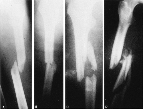
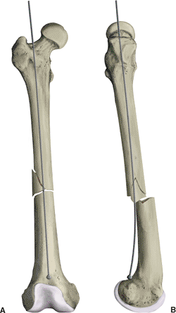
femur fractures. Winquist and Hansen developed a classification based
on the amount of comminution (Fig. 21.1). Type
I and II fractures are characterized by stable bone contact between the
proximal and distal fragments and are considered length stable. Type
III and IV comminution results in limited or no contact between the
proximal and distal fragments, and static interlocking is required to
maintain correct limb length and rotation.
include simple or comminuted fractures presenting below the lesser
trochanter and extending distally to within 7 cm of the knee. Most
grade I and II open femoral-shaft fractures can be treated with reamed
intramedullary nails. Isolated grade III fractures may be better
treated with aggressive wound management, temporary external fixation,
and delayed intramedullary fixation. Patients with multiple injuries,
including open femur fractures, require early skeletal stabilization to
prevent pulmonary compromise. In these circumstances, a nonreamed
intramedullary nailing or external fixation may be biologically
attractive. However, the mechanical benefits of reaming with insertion
of a larger nail, which provides more stability and strength, are
sacrificed.
 |
|
Figure 21.1. Winquist–Hansen fracture classification based on the amount of comminution.
|
active local or systemic infections. Antegrade nailing in adolescents
with open growth plates can damage the blood supply to the femoral
head, causing osteonecrosis. These fractures may be better treated
through use of flexible intramedullary nails, which are inserted
retrograde proximal to the distal femoral-growth plate. Due to a higher
incidence of infection when reamed nailing is performed after a
prolonged period of initial external fixation, nailing should be used
with caution. Other contraindications to nailing include patients with
very narrow medullary canals or those with preexisting deformities that
would preclude closed nailing.
trauma should be evaluated for other injuries. Trauma evaluation and
resuscitation via a multidisciplinary approach is necessary in patients
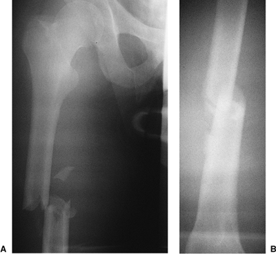
with multiple injuries. High-quality, full-length anteroposterior (AP)
and lateral radiographs of the femur should be obtained to evaluate the
fracture (Fig. 21.2). The fracture location and
the degree of comminution should be assessed on plain films.
Ipsilateral fractures of the hip or femoral condyles must be ruled out
before nailing is undertaken. Specific hip or knee films are often
necessary for visualizing these fractures. Unrecognized nondisplaced
fractures in these areas may displace during nailing. Once recognized,
these fractures may be amenable to fixation with percutaneous screws.
Osteoarthritis of the hip joint with a flexion contracture may limit
hip motion on the traction table and make nailing difficult when the
patient is in the supine position. When severe comminution or segmental
defects exist, full-length films of the opposite femur may be helpful
in determining appropriate length.
medullary canal diameter and the degree of curvature of the intact
femur. Patients with extremely small intramedullary canals
may
require specially sized implants; the size should be determined
preoperatively to ensure implant availability. The remodeling process
associated with aging and osteoporosis often leads to an increase in
the diameter of the medullary canal. In these patients, insertion of
very-large-diameter nails is not necessary because stability is better
achieved with 12- to 14-mm nails that are statically locked. The
increased stiffness of large-diameter nails can cause iatrogenic
comminution during insertion into brittle osteoporotic bone. Also, the
curve of the implant must match the curve of the femur.
 |
|
Figure 21.2. AP radiograph of the right femur showing a transverse mid-diaphyseal fracture with minimal comminution.
|
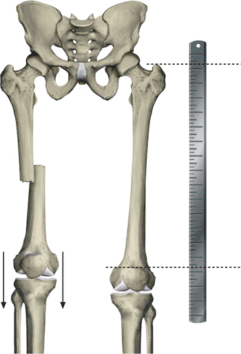
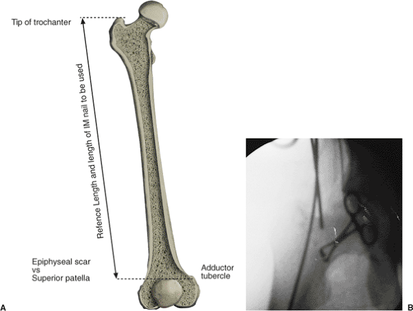
nail of appropriate length requires a reference length. We use the
distance between the tip of the greater trochanter and the adductor
tubercle to determine length. A radiograph of the intact femur with a
radiopaque ruler placed along the thigh (Fig. 21.3) should be obtained.
with or without a fracture table. The lateral decubitus position allows
improved access to the piriformis fossa, especially in large patients
or those with ipsilateral hip disease and concomitant decreased range
of motion. However, patients with multiple injuries who are placed in
the lateral position may experience respiratory compromise. In
addition, valgus angulation of the fracture, difficulty determining
proper rotation, venous congestion caused by pressure of the perineal
post, and greater difficulty inserting distal locking screws are
disadvantages to lateral positioning.
of setup, less respiratory compromise, better fracture alignment, and
easier distal-screw insertion. However, the surgeon will have greater
difficulty establishing the correct starting point in the piriformis
fossa. With the recent introduction of trochanteric entry nails, this
determination has become less of a problem.
 |
|
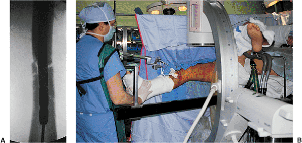
Figure 21.3.
Preoperative evaluation of leg length. For simple fractures with limited comminution, the fracture can usually be reduced with minimal problems and the correct limb length restored. In patients with Winquist III and IV fracture comminution, length is reestablished by use of the contralateral intact femur as a reference. The length between the tip of the trochanter and the adductor tubercle is determined. Intraoperatively, the length of the fractured femur is adjusted by using traction to duplicate the correct trochanter–adductor tubercle length. This measurement can be confirmed through use of two overlapping guide wires of the same length. |
on a fracture table through which fracture reduction is achieved via
sustained longitudinal traction with or without a skeletal pin. A
perineal post provides a fulcrum against which traction is applied. The
design of most fracture tables allows circumferential access to the
extremity for manipulation, surgical exposure, and imaging. The
decision to use either a fracture table or a radiolucent table in
patients who have experienced multiple traumas and who require
simultaneous or sequential surgical procedures should be made on a
case-by-case basis.
be performed on a radiolucent table. Traction can be applied manually
or with the use of a femoral distractor. Nailing can be performed
through an antegrade or retrograde approach. The technique works best
when nailing is done less than 24 hours after injury. Set up time is
minimal, and access to the proximal femur is improved by adducting the
limb. Disadvantages with this technique include difficulty visualizing
the hip and proximal femur in the lateral projection, difficulty
reducing and holding the fracture alignment, risk to the femoral
neurovascular structures, and blockage of the operative field by the
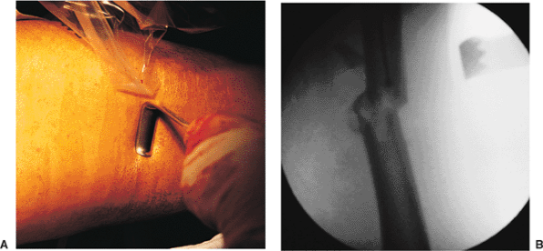
femoral distractor (Fig. 21.6).
fracture table and external manipulation. An in-line boot or a
proximal-tibial or distal-femoral pin traction is utilized, and
the fracture alignment is checked with the image intensifier (Fig. 21.7). Occasionally leg manipulation by the surgeon or a crutch may be useful for reduction of an angulated fracture (Figs. 21.8 and 21.9).
To minimize the risk of a pudendal nerve palsy, the traction is
decreased during the prep, drape, and proximal exposure. Frequently a
small-diameter nail may be used in the proximal fragment to reduce a
flexed and externally rotated proximal
fragment.
In addition, most implant manufacturers include a small-diameter
intramedullary manipulation rod in the nailing sets for this purpose.
 |
|
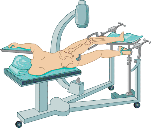
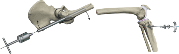
Figure 21.4.
Lateral decubitus operative position. Access to the proximal femur is facilitated by increased hip flexion, which minimizes interference of the insertion instrumentation with the patient’s torso. A drawback to this technique is that pulmonary function is slightly compromised, the setup is time consuming, and venous congestion can be caused from the peroneal post compressing the medial thigh and femoral vessels. |
 |
|
Figure 21.5.
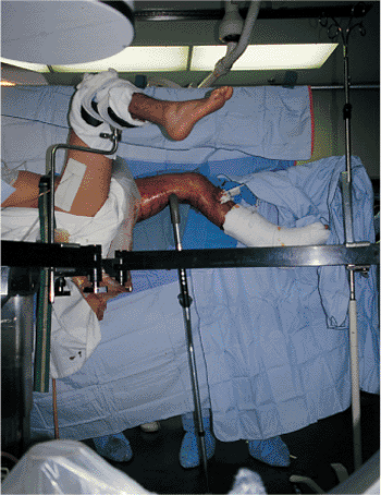
Supine operative position. To gain better access to the proximal femur on the operative side, the patient’s arm is positioned above the body, and the torso is shifted away from the injured side. The operative limb is adducted at the hip. Rotational alignment is obtained with the knee flexed and the foot hanging free. Traction should be applied by using a Steinmann pin placed at the level of the tibial tubercle. The attachment points for the traction bow should be placed close to the skin to avoid bending the Steinmann pin when traction is applied. Bending of the pin dissipates the traction force and produces difficulties in pin removal. The protruding Steinmann pin should be cut close to the bow and the remaining sharp ends should be covered with tape to avoid injury to health-care personnel. |
 |
|
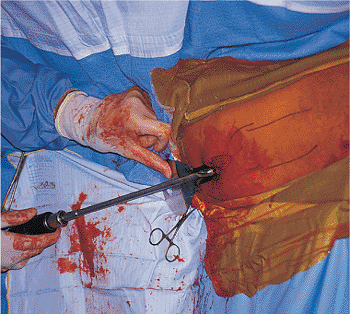
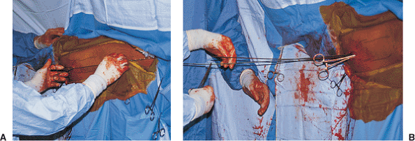
Figure 21.6.
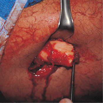
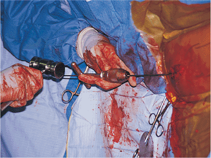
Open fracture management. An open fracture wound should be debrided before nailing. The bone ends should be inspected and carefully cleaned with a curette. Surgical extensions of the incision should be closed, and the original wound left open. At the end of the debridement, all of the instruments, gowns, gloves, and drapes should be changed, and the intramedullary nailing should be treated as a separate procedure. |
 |
|
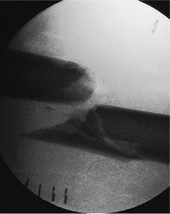
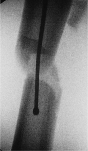
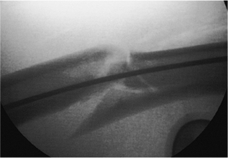
Figure 21.7. Fracture alignment. Once the patient is positioned on the fracture table, the distal fragment is posteriorly displaced.
|
 |
|
Figure 21.8.
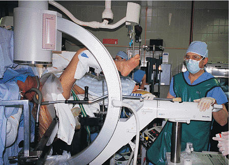
Fracture reduction. A crutch is placed between the floor and the posterior aspect of the leg to assist reduction. This places the distal fragment in a neutral position. The push-button expandable crutch allows precise intraoperative adjustment and greater flexibility in reduction. |
 |
|
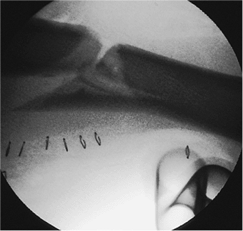
Figure 21.9.
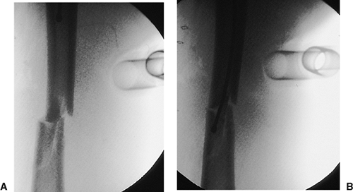
Fracture reduction. This lateral view shows the fracture after correction, with use of a crutch, of the posterior displacement of the distal fragment. |
have developed nails designed to enter through the tip of the greater
trochanter. While technically easier to use than the classic piriformis
entry nails, concerns exist about compromise of the hip abductor
mechanism in patients undergoing trochanteric-entry nailing. To date,
no long-term outcome studies have been completed on hip function
following trochanteric nailing. We are hesitant to recommend its
routine use, particularly in young trauma patients, until
evidence-based medical studies support its widespread use. For this
reason, we still advocate the use of a piriformis entry point for the
majority of antegrade nailing procedures.
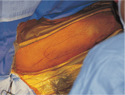
for proper nail placement and fracture reduction. A longitudinal
incision 6 to 10 cm is made over the greater trochanter and in-line
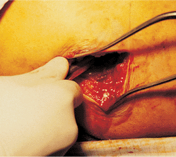
with the femur (Fig. 21.10). The fascia overlying the abductors is incised, and the muscle is split in-line with its fibers down to the piriformis fossa (Fig. 21.11).
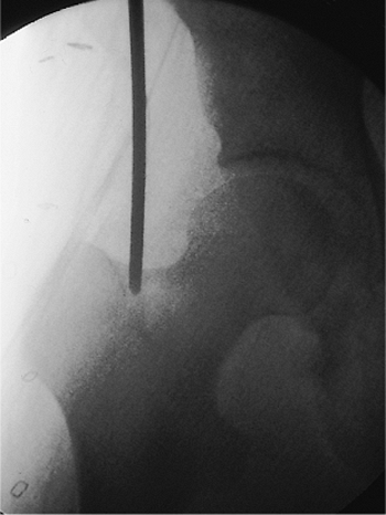
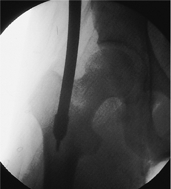
A guide pin is placed in the piriformis fossa, and its position is
confirmed with fluoroscopy. The tip should be centered directly in-line
with the medullary canal as seen in both the AP and lateral views.
Medial portal placement should be avoided because it may cause a
femoral-neck fracture. Portal placement laterally may lead to
comminution and varus alignment in proximal fractures. Once the pin is
properly positioned in the piriformis fossa and is confirmed
fluoroscopically, the femur is opened with a cannulated drill. In an
alternative, an awl may be placed in the piriformis fossa and the
proximal femur opened by hand (Figs. 21.12,21.13,21.14,21.15,21.16,21.17,21.17,21.18,21.19,21.20)
canal under fluoroscopic control. A ball tip is essential to prevent
complications while reaming. The distal 2 cm of the tip is typically
bent and used to direct the wire into the displaced distal fragment.
The guide wire should be placed centrally in the distal fragment
because eccentric placement may cause
comminution or mal-alignment (Figs. 21.21,21.22,21.23,21.24,21.25,21.26,21.27,21.28,21.29,21.30,21.31,21.32,21.33,21.34,21.35,21.36,21.37).
The use of a small-diameter, cannulated, intramedullary, manipulation
device can be very helpful in aligning the fracture and facilitating
guide wire passage.
 |
|
Figure 21.10.
Surgical incision planning. A 6- to 10-cm longitudinal incision is made just proximal to the tip of the greater trochanter. To accommodate distal locking, the surgical field must include the distal femur. |
 |
|
Figure 21.11.
Incision and dissection. The incision has been made and the dissection carried through the subcutaneous tissue and the fibers of the gluteus maximus down to the posterior edge of the gluteus medius. The tip of the greater trochanter and the piriformis fossa are localized by digital palpation. |
 |
|
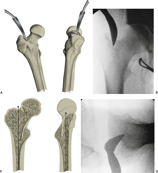
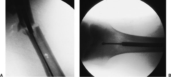
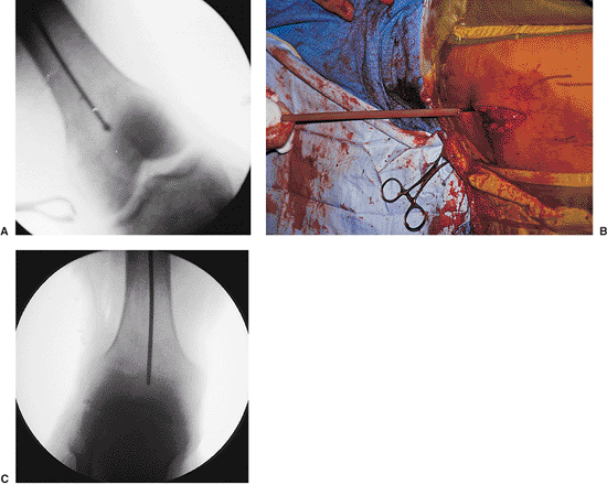
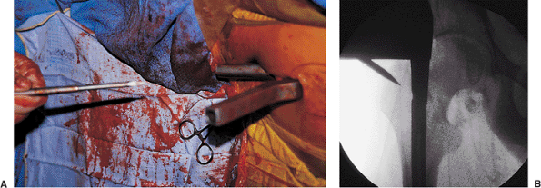
Figure 21.12.
Femoral entry-portal establishment with Kuntscher awl. In an alternative technique, a curved awl can be used for establishing an entry portal in the proximal femur (A). Initial position of the awl established by digital palpation should be confirmed radiographically with the c-arm. The AP and lateral views should include images of the greater trochanter, femoral head, and the proximal portion of the medullary canal (B). The surgeon should imagine a line passing down the center of the medullary canal and projecting out the top of the femur (C). The entry portal should be established exactly where this line emerges in the AP view (D). |
 |
|
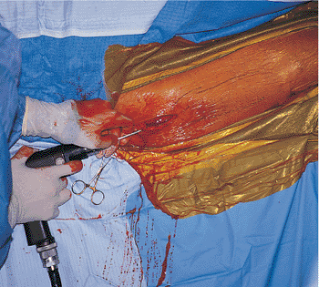
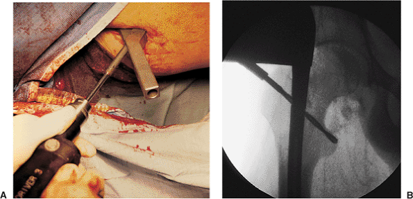
Figure 21.13.
Femoral entry portal establishment with cannulated drill. As shown here, a 5/32 inch Steinmann pin is guided radiographically and drilled into the piriformis fossa. |
 |
|
Figure 21.14.
Steinmann-pin placement. The correct position of the Steinmann pin as it enters the top of the femur at a point where the line defining the center of the medullary canal would emerge from the top of the bone. |
 |
|
Figure 21.15.
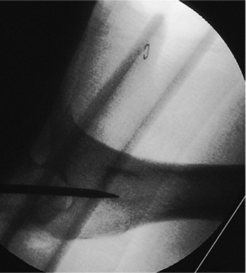
Steinmann-pin placement. As in the AP view, the lateral view of the proximal femur shows that the 5/32 inch Steinmann pin penetrates the bone exactly at a point where the line defining the center of the medullary canal emerges from the top of the bone. |
 |
|
Figure 21.16.
Cannulated drill with reamer. The cannulated drill is inserted with the soft-tissue protector in place over the 5/32 inch Steinmann pin. |
 |
|
Figure 21.17.
Reamer placement. The 13-mm end-cutting reamer is placed over the 5/32 inch Steinmann pin, producing a precisely located entry portal. Power drilling with a sharp 13-mm end-cutting reamer is a superior method for the establishment of an entry portal in the tough proximal-femoral bone in a young patient. The use of this special cannulated reamer over a 5/32 inch Steinmann pin avoids slippage, which can occur with the curved or T-handled awl. The hip must be adequately adducted of the hip. |
 |
|
Figure 21.18.
Reamer placement. Individual anatomic variations sometimes prohibit directing the 5/32 inch Steinmann pin down into the femur along the axis of the medullary canal. In these cases, the pin should be inserted into the femur only a few centimeters. Once the cannulated drill is passed into the top of the femur, the shaft of the drill can be pushed medially close to the patient to redirect the cutting tip down the medullary canal. |
used. Then successive side-cutting reamers, increasing in 1.0-mm
increments, are used until the reamers begin cutting
into
the endosteal surface, which is perceived as manual resistance and
audible chatter. The reamer diameter is then increased in only 0.5-mm
increments to minimize heat generation and the likelihood of
incarcerating the reamer head in the medullary canal. The reamer should
be advanced through the isthmus until resistance is lost, which
indicates that the reamer head has entered the widened portion of the
medullary canal. Although the ball-tipped guide wire extends the full
length of the femur, the cancellous bone in the distal metaphysis
should not be reamed. Better fixation will be achieved if the nail can
be impacted into cancellous bone. The canal should be reamed 1.0 to 1.5
mm more than the diameter of the desired nail to be inserted.
Improvements in metallurgy and manufacturing techniques have enhanced
the strength of intramedullary nails, permitting successful fixation
with smaller-diameter nails. In most cases, we use 11.0- to 12.0-mm
diameter nails in female patients and 11.0- to 13.0-mm-diameter nails
for male patients.
 |
|
Figure 21.19.
Enlargement of the medullary canal with a T-handled awl. Because the shaft of the 13-mm end-cutting entry-portal reamer is rigid, passing the reamer straight down the medullary canal may be impossible. In these cases, a T-handled awl, which has a more flexible shaft, can be introduced to complete the path from the metaphysis into the medullary canal. |
 |
|
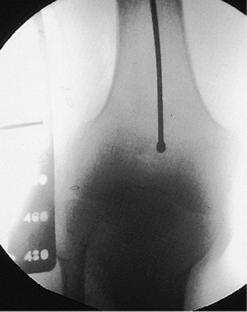
Figure 21.20.
T-handled awl. This radiographic view of the proximal femur shows the curved T-handled awl being passed into the medullary canal. |
 |
|
Figure 21.21.
Ball-tipped guide-wire placement. The ball-tipped reaming guide wire is held by a T-handled chuck and introduced into the entry portal. The guide wire can be rotated as it is advanced through pressure on the T-handled chuck. |
 |
|
Figure 21.22.
Ball-tipped guide-wire placement. Because of the curved bend in the end of the guide wire, the ball tip will sometimes encounter resistance as it is passed through the metaphysis. |
 |
|
Figure 21.23.
Ball-tipped guide-wire placement. The T-handled chuck is clamped onto the guide wire close to the entry wound to optimize control and minimize wire deformation. When a guide wire with a curved tip is used, the T-handled chuck will permit rotational manipulation of the guide wire. Resistance can be overcome by light blows to the T-handled chuck. If great resistance is met, the position of the ball tip should be carefully identified with the image intensifier on AP and lateral views. The tip may need to be withdrawn and repositioned. |
 |
|
Figure 21.24.
Ball-tipped guide-wire placement past the fracture site. If small amounts of residual translation exist at the fracture site, the guide wire may be passed if the surgeon takes advantage of the reestablished bend at the end of the wire. Passage of the guide wire is greatly facilitated by the use of a brief period of live fluoroscopy. Successful passage into the opposite medullary canal can be confirmed by noting that the guide-wire tip is contained within the bone and crosses cortical margins into the soft tissues. To further confirm the location of the guide wire, the surgeon can rotate it. Lateral views are necessary to confirm the correct position of the wire within the medullary canal. |
 |
|
Figure 21.25.
Fracture reduction with crutch. When the fracture shows valgus angulation or medial displacement of the distal end of the proximal fragment, an unscrubbed assistant can apply reducing force in the coronal plane via a crutch. |
 |
|
Figures 21.26. A,B.
Fracture reduction with crutch. A combination of maneuvers can be used to reduce the fracture in the sagittal plane. A crutch is often needed to support the distal fragment, which is pulled toward the floor by the two heads of the gastrocnemius muscle. The proximal fragment is pulled anteriorly by the hip flexors. Manual pressure applied on the anterior thigh may assist with reduction. Radiographic conformation of the crutch helps ensure fracture reduction and allows passage of the bead-tipped guide wire. |
 |
|
Figures 21.27. A,B.
Fracture reduction with retractors. When the fracture shows varus angulation or medial displacement, reducing force can be applied in the coronal plane through the pressure provided by sterile retractors. |
 |
|
Figure 21.28.
Fracture reduction with small-diameter nail or reducing tool. A more powerful reducing force may be applied with the use of a small-diameter nail or reducing tool. When proximal diaphyseal fractures are encountered, this instrument can be used to control the flexed, externally rotated, and abducted proximal fragment during reduction. |
 |
|
Figure 21.29.
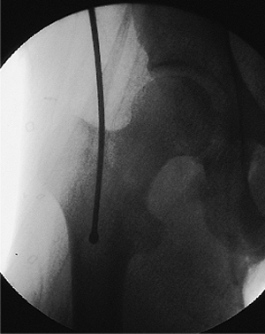
Guide-wire passage past the fracture site. Guide-wire passage into the distal fragment is confirmed. Both AP and lateral views should be taken to assure that the wire is in the medullary canal. |
 |
|
Figure 21.30.
Confirmation of proper guide-wire placement. The fracture should be reduced before guide-wire insertion and maintained in this position throughout reaming, nail insertion, and distal screw fixation. Correct reduction is confirmed when the guide wire passes down the center of the medullary canal to the level of the adductor tubercle. |
 |
|
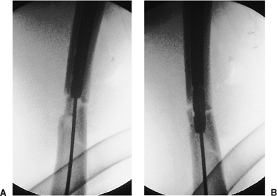
Figure 21.31. A,B.
Proper ball-tip guide-wire placement. A posteriorly placed wire can be seen as central on the AP view. This emphasizes the need to obtain both views to confirm containment of the wire in the medullary canal. |
 |
|
Figure 21.32.
Guide-wire placement. Eccentric guide-wire placement can lead to excessive reaming on one cortex and comminution during nail insertion. |
 |
|
Figure 21.33.
Femoral intramedullary nail size. Proposed nail length is based on the measurement from tip of the greater trochanter to the adductor tubercle. |
reestablished intraoperatively through use of the ball-tipped guide
wire and the referenced length previously determined. A second guide
wire, equal in length to the ball-tipped guide wire, is inserted into
the wound to the level of the entry portal at the top of the femur. A
clamp is placed on the guide wire at
the
point where it overlaps the tip of the ball-tipped guide wire. The
distance between the clamp and the free end of the second guide wire is
measured to estimate the distance from the tip of the greater
trochanter to the adductor tubercle. This distance is compared with the
reference measurement made preoperatively on the contralateral intact
femur. Adjustments must be made with traction to correct any
discrepancy with this distance. Many nailing sets come with
direct-read, cannulated, depth gauges, which are very accurate.
 |
|
Figures 21.34. A,B.
Ruler measurement. Reestablishing the correct length of the fractured femur and choosing the correct length of the intramedullary nail both require the use of a reference length, which is the distance between the tip of the greater trochanter and the adductor tubercle; this can be measured through use of a radiopaque ruler held lateral to the thigh at the level of the femur. |
 |
|
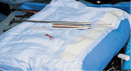
Figures 21.35. A,B.
Wire measurement. A second guide wire equal in length to the ball-tip guide wire is inserted into the wound to the level of the entry portal at the top of the femur. A clamp is placed on the guide wire at the point where it overlaps the tip of the ball-tipped guide wire. The distance between the clamp and the free end of the second guide wire is measured and used as an estimate of the distance from the tip of the greater trochanter to the adductor tubercle. This distance is compared with the reference measurement made preoperatively on the contralateral intact femur. Adjustments must be made with traction to correct any discrepancy with this distance. |
 |
|
Figure 21.36.
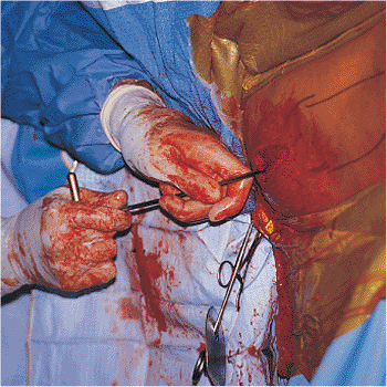
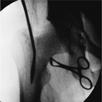
Reaming. The soft-tissue protector should always be used to avoid injury to the skin and muscle from the rotating reamer shaft. A lap-pad strap is tied to the protector to prevent it from falling to the floor. When the reamer is pulled back, a Kocher clamp is used to grasp the guide wire; the surgeon must avoid extracting the guide wire across the fracture site. The initial reamer should be a small end-cutting type to create a path for subsequent reamers. |
 |
|
Figures 21.37. A,B.
Reaming. To avoid excessive pressure in the medullary canal, reamers should be sharp, have deep flutes, and have a small shaft relative to the diameter of the reamer head. In addition, the reamer should be advanced slowly, and multiple passes should be made with each reamer size. Side-cutting reamers are used to enlarge the canal to 1.0 mm larger than the intended nail diameter. The diameter of the reamers can be initially increased by 1-mm increments. Once the reamers begin to bite into cortical bone, the reaming diameter should be increased in 0.5-mm increments. If excessive resistance is encountered with a particular reamer, the last diameter that successfully passed should be reintroduced, and several more passes should be made with this reamer to remove additional bone. Overreaming from 1.0 to 2.0 mm is done when the femur has a significant bow, when the isthmus is long and narrow, or if the nail is difficult to drive. |
wire is positioned corresponding to the distal extent of the desired
nail. For the majority of shaft fractures, this corresponds to the
adductor tubercle. In distal-third fractures, the ball tip is placed
just proximal to the intercondylar notch. In these cases, the surgeon
should plan to place two distal-locking screws, which prevent toggle in
the distal fragment. Rarely, the nail needs to be customized through
trimming of the distal tip, which allows for a more distal
locking-screw placement.
is difficult to reestablish by reapproximating the main fragments. For
this reason, the traction must be adjusted so that the reference length
(greater trochanter to adductor tubercle) determined preoperatively can
be reproduced intraoperatively through use of the ball-tipped guide
wire and a second guide wire of equal length. Failure to compare the
intraoperative length with the reference length may result in the femur
being fixed in a shortened or lengthened position.
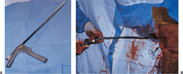
insertion. The tip of the guide wire is often bent to facilitate
cannulation of the distal fragment, and the width of the ball is often
wider than the inner diameter of the nail tip. Consequently, the curved
ball-tipped guide wire may become trapped if used for nail insertion.
In addition, a larger-diameter guide wire that more completely fills
the inner diameter of the nail tip is preferable for nail insertion. If
the nail is inserted over a thin guide wire, the larger inner diameter
at the nail tip can allow the nail to displace into an eccentric
position. This can cause inadvertent incarceration on the cortex of the
distal fragment. Therefore, a straight, smooth, large, guide wire is
necessary. A plastic sheath is used to maintain canal continuity while
the ball-tipped guide wire is exchanged for the smooth guide wire (Fig. 21.38).
 |
|
Figures 21.38. A–C.
Guide-wire exchange. The purpose of the spherical end on a ball-tipped guide wire is to assist in extracting an incarcerated reamer. However, because of the ball, this wire should not be used for nail insertion. The ball-tipped reaming guide wire is replaced by a slightly larger diameter nonbeaded guide wire (nail-driving guide wire), which fills the nail, minimizing the risk of engaging the cortex of the distal fragment. A plastic exchange tube should be used to avoid displacement of the fracture and to simplify guide-wire exchange. A metallic marker at the tip of the tube allows radiographic confirmation that the tube has passed the fracture site. |
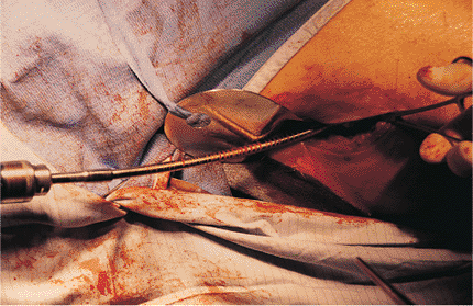
the smooth-tipped guide wire. To minimize the likelihood of iatrogenic
comminution, fluoroscopic control should be used when the nail crosses.
The nail is impacted smoothly with a mallet until the proximal nail is
flush with or just below the greater trochanter. The distal end of the
nail should be inserted to the chosen reference point (adductor
tubercle for diaphyseal fractures and adjacent to the intercondylar
notch for distal-third fractures) (Figs. 21.39,21.40,21.41,21.42).
Most nails are designed with transfixion screws in the coronal plane.
To achieve proper rotation, the nail must be controlled with the
driver-and-proximal locking device during insertion.
connected to the driver. Nail systems are used with either transverse
or diagonal, proximal, locking screws (Figs. 21.43,21.44,21.45,21.46).
A single cross-locking screw is placed either diagonally from the
greater to lesser trochanter or transversely across the femoral
diaphysis. Failure to seat the nail fully may lead to superior
placement of a diagonal screw, predisposing a loss of fixation or
femoral-neck fractures.
 |
|
Figures 21.39. A,B.
Intramedullary nail assembly and insertion. The proximal targeting nail and driving device is secured to the top of the nail. The nail driver can loosen after multiple mallet blows during insertion and should be retightened frequently. The nail is inserted over the guide wire into the femur, with the handle of the targeting device projected parallel to the floor so that the proximal and distal screw holes will be located in the coronal plane. |
The flexibility of target devices mounted on the image intensifier has
caused inaccurate screw insertion. The device, which requires direct
attachment to the image intensifier, also lost popularity because
surgeons are afraid of voiding the warranty on the image intensifier. A
number of manufacturers have designed target devices for distal
locking, which attach to the proximal end of the nail. The tendency for
open-section intramedullary nails to deform torsionally on insertion
has caused concern about the alignment between the target device and
the distal screw holes. In addition, the length of these devices makes
them subject to displacement and inaccurate screw placement,
particularly when used in a patient placed in the supine position.
Because of these problems, most
surgeons
have resorted to the use of hand-held devices, including drill guides,
awls, sharp pins, and drill bits, and the freehand technique.
Radiolucent offset drill attachments, which are used in conjunction
with standard power drills, have been developed to allow direct
drilling under radiographic control.
 |
|
Figures 21.40. A,B.
Intramedullary nail advancement. To avoid incarcerating comminuted fragments that lie in the path of the nail, the proximal end of the nail is pushed medially into the patient such that the distal end of the nail is directed laterally away from the fragment. The nail should be advanced slowly under fluoroscopic control. |
 |
|
Figures 21.41. A,B.
Fracture impaction. Once the nail passes into the distal fragment, traction is released to allow impaction at the fracture site. Impaction is aided by extending the knee and holding the foot firmly. This step is omitted in severely comminuted fractures in which femur length has already been adjusted by traction. |
 |
|
Figure 21.42.
Intramedullary nail placement. When the nail is fully inserted, the target device should touch the greater trochanter. Radiographic confirmation of the target device is necessary because soft tissues can impinge and artificially elevate the targeting device, leaving the nail prominent. |
 |
|
Figures 21.43. A,B.
Proximal screw insertion with awl. The path of the proximal screw is diagonal, and the drill bit engages the lateral cortex at an acute angle. This angle can cause distal migration of the drill tip. To avoid this outcome, an awl is used to dimple the cortex before drilling. |
 |
|
Figures 21.44. A,B.
Drilling the proximal screw hole. On the AP view, the lesser trochanter appears to be in the coronal plane; however, it projects posteromedially. It is not necessary to drill to the apparent tip of the lesser trochanter because the drill bit exits anterior to the lesser trochanter. |
 |
|
Figure 21.45.
Depth gauge and tissue protector. If measuring and hooking the opposite cortex with a depth gauge is problematic, depth can be estimated radiographically. This image shows the difference between the length of the depth gauge and the tissue protector. The tissue protector is 1.0 cm shorter than the sleeve on the depth gauge. To obtain correct the measurement, the surgeon should remove the soft-tissue protector and use the depth gauge with its own sleeve. |
 |
|
Figure 21.46.
Proximal screw placement. Many patients complain of pain at the trochanter because of a prominent head on the proximal screw. To decrease this discomfort, the screw head can be partially buried. It is a self-tapping fully threaded screw, and the nail is threaded so the surgeon can countersink the screw effectively. |
 |
|
Figure 21.47.
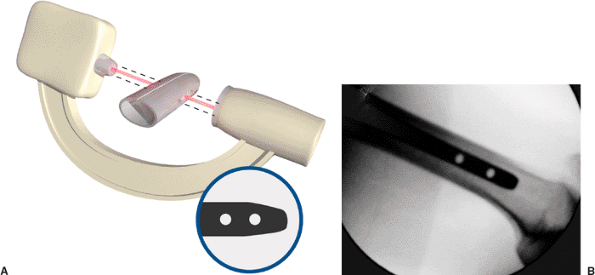
Distal fixation. Correct rotational alignment of the fracture should be confirmed before distal fixation. The c-arm should be positioned to obtain an optimal lateral view of the distal end of the nail. The goal is to pass the beam exactly in-line with the axis of the screw holes (A). This position has been obtained when the holes appear perfectly round (B). An elliptical appearance of the holes suggests mal-alignment of the beam. |
 |
|
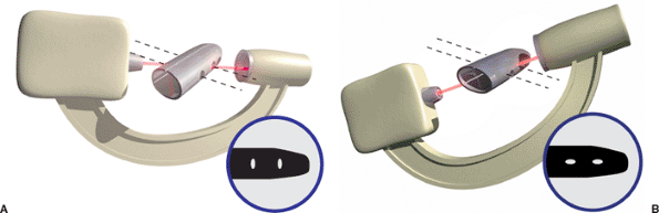
Figure 21.48. Illustration of oblique, distal, screw holes resulting from rotation. A. Mal-alignment of the beam in the coronal plane makes the holes appear as vertical ellipses. B. Mal-alignment in the sagittal plane makes holes appear as horizontal ellipses.
|
 |
|
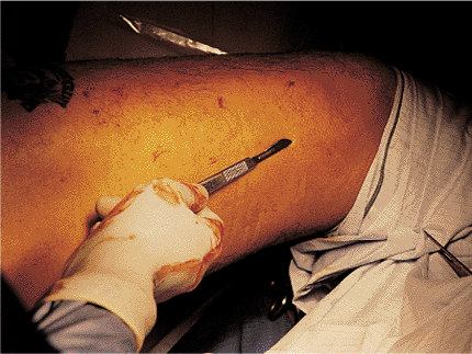
Figure 21.49.
Distal entry-hole targeting. The tip of the scalpel is positioned on the skin over the screw hole so that once correct targeting is achieved, an immediate incision can be made. |
 |
|
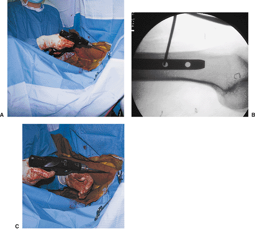
Figures 21.50. A–C.
Distal entry-hole drilling. The drill is held out of the x-ray beam. The tip of the drill bit is against the lateral cortex and exactly centered on the proximal screw hole. With fluoroscopy off, the drill is lowered in line with the axis of the x-ray beam and screw hole. Continuous pressure must be kept on the tip of the drill as an assistant stabilizes the femur. In addition to these steps, the use of a sharp-tip drill bit helps avoid migration of the drill bit. |
 |
|
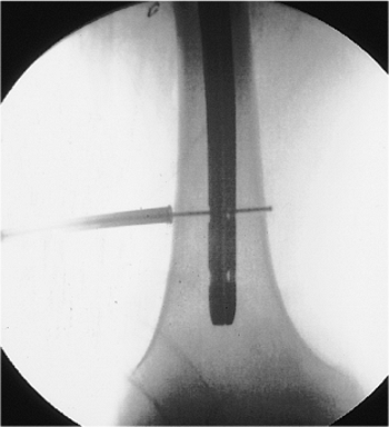
Figure 21.51.
Distal fixation-hole depth measurement. Depth measurement for correct screw-length determination. Five millimeters should be added to the screw length to ensure projection beyond the opposite cortex, which will facilitate removal if the screws break. |
 |
|
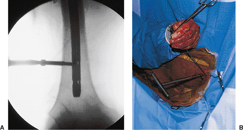
Figures 21.52. A,B.
Distal screw insertion. The screw driver is used to define the axis of the first screw, which will be used to assist with the insertion of the second screw. |
 |
|
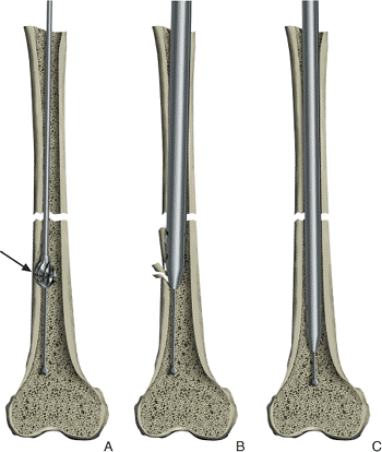
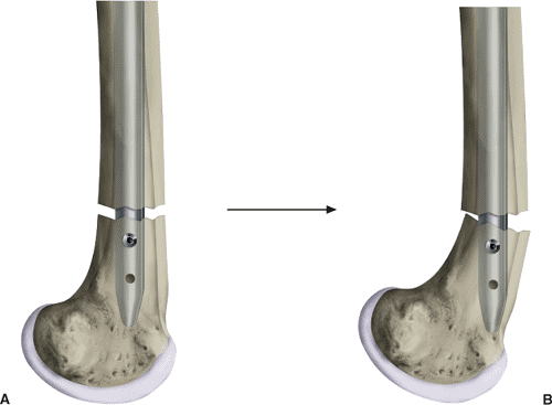
Figure 21.53. A,B.
Toggle cross-locking a fracture in the distal third of the femur with a single screw permits the short distal fragment to toggle or rotate on the axis of the screw. |
 |
|
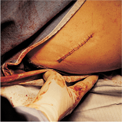
Figure 21.54. Wound closure.
|
distal interlocking. Imperative to success, the image intensifier must
be properly positioned directly perpendicular to the femur and centered
over the distal screw holes. With proper positioning, the holes in the
distal nail should appear as perfect circles and not as ellipses. A
long Kirschner (K) wire is placed on the skin in the center of the
hole; its location is confirmed via fluoroscopy. A 2-cm skin incision
is made with blunt dissection to the lateral femoral cortex. The wire
is then tapped into the bone in the center of the hole, creating a
starting point to facilitate drilling. Fluoroscopic confirmation that
the drill bit has successfully traversed the nail is essential before
the surgeon drills the opposite cortex.
and accomplished via the c-arm. Both screw holes should be filled in
distal-third fractures because the diameter of the distal fragment is
larger than that of the nail, and fixation with a single screw could
lead to rotation of the fragment around the screw and motion at the
fracture site. To enhance screw purchase, two distal screws should also
be used for any diaphyseal fractures in weak osteoporotic bone. If a
reamed nail is used, a single distal screw placed in the more proximal
of the two, distal, nail holes is sufficient for fractures in the upper
and middle thirds. In these cases, the diameter of the medullary canal
at the proximal end of the distal fragment is usually similar in size
to the diameter of the nail, preventing distal-fragment rotation.
location and amount of comminution, age of patient, preoperative
mobility, and extent of coexisting injuries. So that weight will be
transmitted through the bone, early weight bearing is encouraged in the
patient with a transverse or short oblique fracture in which the
contact between the two major fragments is unstable. When comminution
prevents transmission of weight through the bone, 6 to 8 weeks of
partial weight bearing is recommended to permit callus formation.
Patient pain is usually the limiting factor for weight bearing.
static locked mode. This is advantageous, even in stable transverse
fractures, because it helps to control rotation. Dynamization (the
removal of proximal or distal screws from a statically locked nail) may
be useful to allow impaction in those few fractures that do not show
progressive healing 4 to 6 months after nailing.
motion, resistive muscle strengthening, gait training, and pool
therapy. These therapies speed rehabilitation, enhance fracture
healing, and increase the ultimate level of functional recovery.
after surgery for suture removal and wound inspection. AP and lateral
radiographs are obtained to inspect the implant position, fracture
alignment, and progress of union immediately after surgery and at 6,
12, and 24 weeks. A final set of radiographs is obtained at 6 months to
document adequate healing of the fracture. The average uncomplicated
femoral-diaphyseal fracture will unite in 3 to 5 months. In the absence
of patellar fractures or knee ligament injuries, patients generally
achieve excellent recovery of knee motion. Several months of exercise
are required to achieve the ultimate range of knee motion. The speed of
recovery and degree of motion are enhanced by early physical therapy.
incidence of the postoperative fracture displacement that leads to
malunion. The majority of malunions results when fractures are
fixed
in a position of mal-alignment. Transverse and short oblique fractures
in the isthmus are naturally aligned because of greater endosteal
contact with the nail. Fractures above and below the isthmus have a
short fragment with a large medullary canal, which predisposes the
fragment to angular mal-alignment unless its position is carefully
controlled.
position of the fragment by visualizing the fracture site under low
magnification (camera close to the limb) and by ensuring that the guide
wire is in the center of the fragment as shown on both AP and lateral
views. If the short fragment is held in correct position during guide
passage, reaming, and nail and screw insertion, mal-alignment will be
prevented. Correct entry-portal placement in the piriformis fossa
in-line with the medullary canal is important in preventing varus
malunions in proximal-third fractures. In addition to avoiding angular
mal-alignment, the correct rotational alignment must be established
before nail insertion. In the supine position, diaphyseal fractures are
aligned by allowing the knee to flex with the foot hanging to the
floor. Proximal placement of the tibial traction pin at the level of
the tibial tubercle will facilitate knee flexion, which improves
rotational alignment and transmits greater traction force along the
femur. More distal placement of the traction pin causes knee extension
when traction is applied. This reduces the force transmitted into the
femur, reduces the rotational moment arm of the distal fragment, and
results in posterior angulation of the femoral fracture.
removal of the distal screws, deformity correction, and reinsertion of
the screws. Angulation of 5 to 7 degrees in any plane is usually well
tolerated; however, mal-alignment of more than 10 degrees usually
requires early revision to avoid late symptoms. Increased comminution
associated with nailing is common and is tolerated as long as the
comminution is between the static locking screws.
locked nails results in a 1% to 2% incidence of nonunion. Introduction
of the nails at a distance from the fracture site avoids direct
dissection and periosteal stripping, thereby preserving the fracture
biology. Systemic (poor nutrition, diabetes, steroids, smoking, etc.)
and local factors (severe periosteal stripping, infection, or vascular
injury) can combine to cause delayed union or nonunion. Each of these
factors must be taken into consideration and treatment plans developed
accordingly.
continuous traction on the perineal post. This complication can usually
be avoided if the nailing is performed on the day of injury. Only
limited traction is needed during this early phase to achieve excellent
reductions. When nailing is delayed, sufficient skeletal traction
should be applied to overdistract the fracture slightly. This
overdistraction should be confirmed through use of a lateral
radiograph. The AP view alone should not be used to determine length
because the film is usually taken parallel to the surface of the bed
rather than the limb, and it can give a false impression of distraction
in the presence of overlap. By maintaining preoperative
overdistraction, the surgeon can more easily reduce the fracture during
nailing without resorting to excessive traction. Pudendal nerve palsies
are usually neurapraxia and frequently resolve in 3 to 4 months.
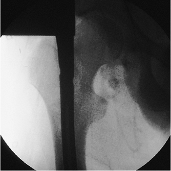
suggest that a femoral-neck fracture more likely represents a missed
injury rather than iatrogenic fracture. Radiographs of the hip must be
examined carefully to rule out a hip dislocation or femoral-neck
fracture. A separate, internal-rotation AP radiograph of the proximal
femur can be very helpful in visualizing the femoral neck.
these combined fractures. They include insertion of multiple cannulated
screws around an existing nail, use of a reconstruction nail, and
employment of multiple cannulated screws with a retrograde locked nail.
insertion of an implant that extends the length of the femur, infection
after closed intramedullary nailing is surprisingly infrequent. The
closed technique, which eliminates dissection at the fracture site,
contributes to the low incidence of infection and nonunion. When
infection does occur, the extent of involvement can vary. The infection
may be confined to the superficial layers of the wound or the hematoma
at the entry wound or the fracture site. These infections can be
treated by intravenous antibiotics and local drainage. Less frequently,
the entire medullary cavity is infected. The inner half of the
thickness of the cortex, devascularized by the reaming, can become an
extensive sequestrum. In this circumstance, treatment requires removal
of the nail and repeated reaming to debride the endosteal cortex. A new
nail or an external fixator may be necessary if the fracture is not
united.
closed right-femur fracture as a result of a head-on motor vehicle
accident. The patient lost consciousness at the site of the accident
and experienced mild retrograde amnesia. On initial examination, the
physician found an obvious, closed, right, midshaft-femur deformity.
The peripheral pulses were intact, and the neurologic examination
showed no abnormalities. Cervical spine, chest, and pelvic radiographs
were normal. A cranial computed tomography (CT) scan was negative for
fracture or intracranial bleed. AP and lateral radiographs of the femur
showed a mid-diaphyseal transverse fracture (see Fig. 21.2). The patient
had an abdominal injury that required exploratory laparotomy. At
surgery, the patient was found to have a complete jejunal transection,
which was subsequently repaired. Immediately after the laparotomy, a
closed intramedullary nailing was performed with a static locked nail.
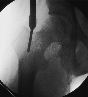
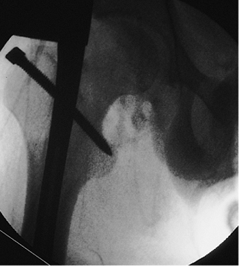
Because the fracture was mid-diaphyseal, a single distal screw was used
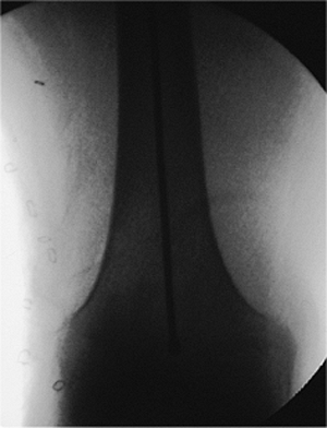
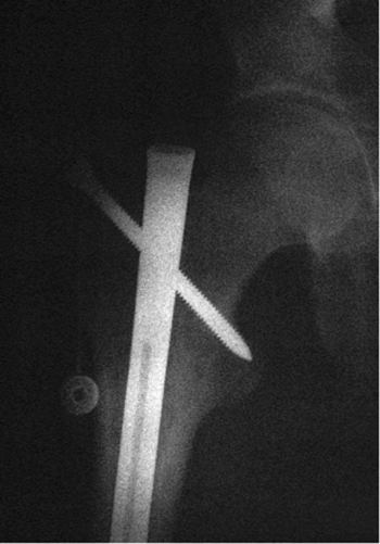
for fixation (Fig. 21.55).
The patient was mobilized on the second postoperative day. The fracture
healed uneventfully in 4 months with excellent restoration of function.
 |
|
Figure 21.55. Postoperative radiograph.
|
RJ, Reilly JP, Poka A, et al. Intramedullary nailing of femoral shaft
fractures, part I: decision making errors with interlocking fixation. J Bone Joint Surg Am 1988;70:1441–1452.