
Editors: Koval, Kenneth J.; Zuckerman, Joseph D.
Title: Atlas of Orthopaedic Surgery: A Multimedia Reference, 1st Edition
Copyright ©2004 Lippincott Williams & Wilkins
> Table of Contents > Section I – Shoulder > Chapter 5 – Orif: Three-Part Fracture of The Proximal Humerus
Chapter 5
Orif: Three-Part Fracture of The Proximal Humerus
Kenneth J. Koval
Eighty-five percent of proximal humerus fractures are
minimally displaced and can be treated with protected immobilization
and early range of motion dependent on fracture stability. However,
controversy exists regarding the optimal treatment of displaced
proximal humerus fractures. Many internal fixation techniques have been
advocated for the treatment of these difficult fractures including
percutaneous pins, intramedullary rods placed antegrade or retrograde,
figure-of-8 tension band wire or suture, and plate and screws. This
chapter illustrates open reduction and internal fixation of a displaced
proximal humerus fracture using Ender nails and a tension band
construct.
ANATOMY
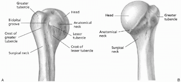
The proximal humerus can be considered to consist of the humeral head, the tuberosities, and the humeral shaft (Fig. 5-1).
The anatomic neck is the junction between the humeral head and the
tuberosities. The surgical neck lies between the tuberosities and the
shaft. The rotator cuff (see Figs. 3-2 and 4-1)
is composed of four muscular divisions: (a) the subscapularis, which
inserts on the lesser tuberosity and acts as an internal rotator of the
glenohumeral joint; (b) the supraspinatus tendon, which inserts on the
greater tuberosity and acts to depress the humeral head into the
glenoid during elevation of the arm; (c) the teres minor and
infraspinatus muscles, which are the external rotators of the shoulder
and also insert on the greater tuberosity; and (d) the biceps tendon,
which lies in the anteriorly directed bicipital groove and provides a
useful anatomic landmark for judging rotational deformity of the
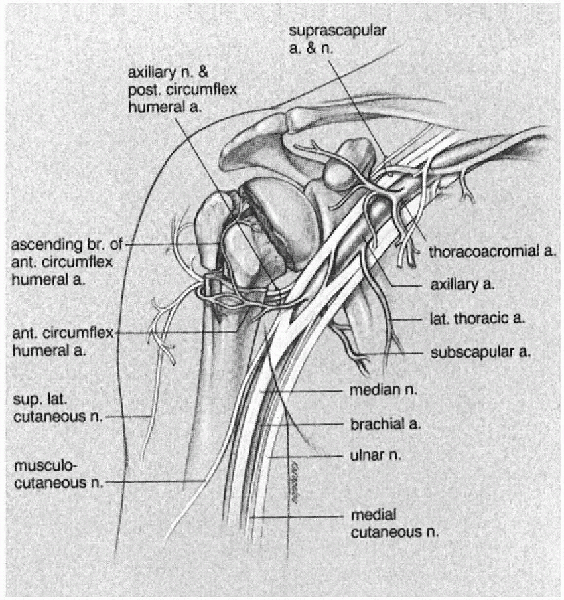
humeral head during operative management. The terminal branches of the
ascending division of the anterior humeral circumflex artery enter the
humeral head through the bicipital groove. Fractures that split the
tuberosities from the head disrupt this small arterial complex and can
result in osteonecrosis of the humeral head (Fig. 5-2).
The anatomic neck is the junction between the humeral head and the
tuberosities. The surgical neck lies between the tuberosities and the
shaft. The rotator cuff (see Figs. 3-2 and 4-1)
is composed of four muscular divisions: (a) the subscapularis, which
inserts on the lesser tuberosity and acts as an internal rotator of the
glenohumeral joint; (b) the supraspinatus tendon, which inserts on the
greater tuberosity and acts to depress the humeral head into the
glenoid during elevation of the arm; (c) the teres minor and
infraspinatus muscles, which are the external rotators of the shoulder
and also insert on the greater tuberosity; and (d) the biceps tendon,
which lies in the anteriorly directed bicipital groove and provides a
useful anatomic landmark for judging rotational deformity of the
humeral head during operative management. The terminal branches of the
ascending division of the anterior humeral circumflex artery enter the
humeral head through the bicipital groove. Fractures that split the
tuberosities from the head disrupt this small arterial complex and can
result in osteonecrosis of the humeral head (Fig. 5-2).
 |
|
FIGURE 5-1. A: Right proximal humerus, anterior aspect. B: Right proximal humerus, posterior aspect.
|
P.53
 |
|
FIGURE 5-2. Right proximal humerus, arteries, nerves, and brachial plexus.
|
CLASSIFICATION
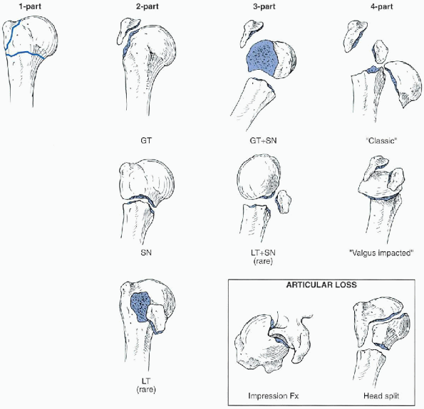
The Neer classification is the most widely used system in clinical practice (Fig. 5-3).
This system is based on the anatomic relationship of the four major
anatomic segments: articular segment, greater tuberosity, lesser
tuberosity, and the proximal shaft beginning at the level of the
surgical neck. Fracture types are based on the presence of displacement
of one or more of the four segments. For a segment to be considered
displaced, it must be either greater than 1 cm displaced or angulated
more than 45 degrees from its anatomic position. The number of fracture
lines is not important in this classification system. For example,
one-part fractures, or minimally displaced fractures, are the most
common type of proximal humeral fractures and account for up to 85% of
all proximal humerus fracture. Although these fractures may have
multiple fracture lines, they are characterized by the fact that none
of the four segments fulfill the criteria for displacement. Hence, they
are considered one part or minimally displaced.
Displaced fractures include two-part, three-part, and
four-part fractures. A two-part fracture is characterized by
displacement of one of the four segments, with the remaining three
segments either not fractured or not fulfilling the criteria for
displacement. Four types of two-part fractures can be encountered
(greater tuberosity, lesser tuberosity, anatomic neck, and surgical
neck). A three-part fracture is characterized by displacement of two of
the segments from the remaining two nondisplaced segments. Two types of
three-part fracture patterns are encountered. The more common pattern
is characterized by displacement of the greater tuberosity and the
shaft from the lesser tuberosity, which remains with the articular
segment. The much less commonly encountered pattern is characterized by
displacement of the lesser tuberosity and shaft from the greater
tuberosity, which remains with the articular segment. A four-part
fracture is characterized by displacement of all four segments.
Neer also categorized fracture-dislocations, which are
displaced proximal humeral fractures—two-part, three-part, or
four-part—associated with either anterior or posterior dislocation of
the articular segment. Neer also described articular surface fractures
that were of two types: impression fractures or head-splitting
fractures. Impression fractures of the articular surface most often
occur in association with chronic dislocations. As such, they can be
either anterior or posterior and involve variable amounts of the
articular surface. Head-splitting fractures are usually associated with
other displaced fractures of the proximal humerus in which the
disruption or “splitting” of the articular surface is the most
significant component.
P.54
 |
|
FIGURE 5-3.
The Neer classification of proximal humerus fractures. This system is based on the anatomic relationship of the four major anatomic segments: the humeral head, greater tuberosity, lesser tuberosity, and the proximal humeral shaft beginning at the level of the surgical neck. Fracture types are based on the presence of displacement of one or more of the four segments. For a segment to be considered displaced, it must be either greater than 1 cm displaced or angulated more than 45 degrees from its anatomic position. (After Neer CS. Displaced proximal humeral fractures: part I. Classification and evaluation. J Bone Joint Surg Am 1970;52A:1077-1089, with permission.) |
INDICATIONS
Functional outcome following fracture is correlated to
residual deformity after healing. Healed fractures with angular
deformity greater than 45 degrees or displacement greater than 1 cm
have poorer results than those with more anatomic reduction. Most
current reports in the literature suggest that the traditional closed
methods of treating displaced proximal humerus fractures have been
disappointing. Therefore, I feel that displaced proximal humerus
fractures are best treated operatively.
Open reduction and internal fixation is the treatment of
choice for most displaced two-part fractures. Currently, open reduction
and internal fixation is the treatment of choice for displaced
three-part fractures of the proximal humerus in younger individuals and
prosthetic replacement in older individuals. Different techniques of
internal fixation have been used for these fractures including plate
and screws, percutaneous pins, tension band wires, and intramedullary
devices. In general, the trend for three-part fractures has been toward
avoidance of plate and screw fixation because of the difficulties in
obtaining adequate fixation in osteoporotic bone. I prefer use of Ender
nails augmented with a tension band suture for stabilization of
three-part proximal humerus fractures. Four-part fractures are usually
treated with prosthetic replacement.
P.55
PREOPERATIVE PLANNING
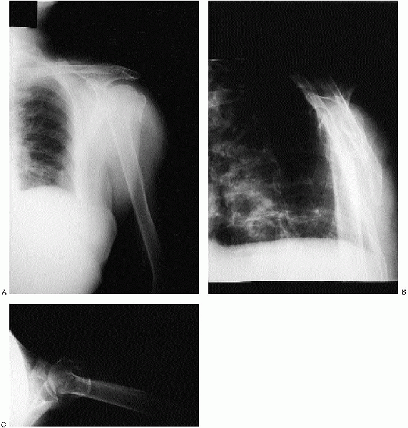
A shoulder trauma series consists of anteroposterior
(AP) and lateral views of the shoulder obtained in the plane of the
scapula and an axillary view (Fig. 5-4). The
scapular AP view offers a general overview of the fracture and is
usually evaluated first. The scapular lateral assists in delineating
the position of the humeral head relative to the glenoid and is
particularly useful in showing dislocations or posteriorly displaced
fragments. The axillary view also permits assessment of the
glenohumeral relationship. Computed tomography (CT) scans of proximal
humeral fractures and fracture dislocations may be indicated when the
trauma series radiographs are indeterminate. CT scans have also been
recommended to evaluate the rotation of fragments and the degree of
tuberosity displacement, as well as articular impression fractures,
head-splitting fractures, and chronic fracture-dislocations.
 |
|
FIGURE 5-4. Anteroposterior (A), Y view (B), and axillary (C) revealing a displaced three-part fracture of the proximal humerus.
|
P.56
 |
|
FIGURE 5-5.
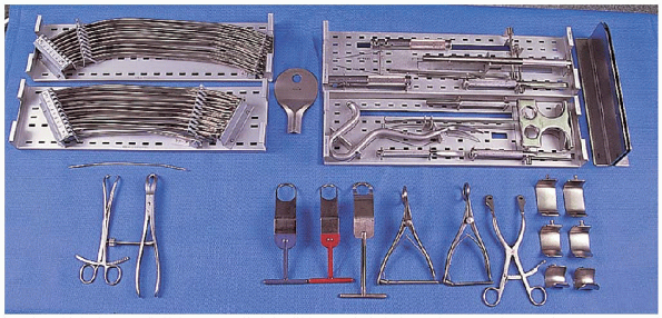
The equipment needed for open reduction and internal fixation of a three-part proximal humerus fracture: Ender nail instrumentation and nail set (top row), large reduction forceps (2) (bottom left), shoulder retractors (bottom right). |
EQUIPMENT
The following equipment is needed (Fig. 5-5):
-
Ender nail instrumentation and nail set
-
Small fragment set
-
Air drill
-
Heavy suture
-
Large reduction forceps
-
Shoulder retractors
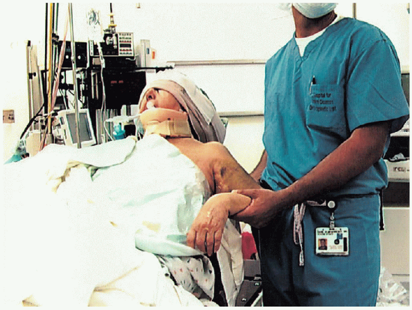
PATIENT POSITIONING
The patient is placed on the operating table in a supine
position. The head of the operating table is elevated approximately 30
degrees in a modified beach chair position (Fig. 5-6).
A small bolster is placed behind the involved shoulder. The patient is
moved off to the side of the table so that the upper extremity can be
placed into maximum extension without obstruction by the operating
table. The patient is secured to the operating table to minimize any
changes in position intraoperatively. The entire upper extremity is
prepped and draped to allow full mobility during the procedure.
 |
|
FIGURE 5-6.
The patient is placed on the operating table in a supine position. The head of the operating table is elevated approximately 30 degrees in a modified beach chair position. The patient is moved off to the side of the table so that the upper extremity can be placed into maximum extension without obstruction by the operating table. |
APPROACH
I
have found that open reduction and internal fixation of most displaced
proximal humerus fractures is most easily performed through a
deltopectoral approach. A straight incision is used; it begins just
lateral to the tip of the coracoid process and extends distally and
laterally to the insertion of the deltoid (Fig. 5-7).
The subcutaneous tissues are divided, and medial and lateral flaps
elevated to expose the deeper muscular layers. The deltopectoral
interval is identified by localization of the cephalic vein.![image]() The cephalic vein is usually retracted laterally with the deltoid muscle (Fig. 5-8). In
The cephalic vein is usually retracted laterally with the deltoid muscle (Fig. 5-8). In
some instances, the cephalic vein is more easily retracted medially
with the pectoralis major. In either case, care should be taken to
preserve the cephalic vein throughout the procedure. The
subdeltoid space is mobilized as is the pectoralis major. The conjoined
tendon muscles are identified, and the clavipectoral fascia divided at
the medial edge of the conjoined tendon muscles. The conjoined tendon
muscles and the pectoralis major are retracted medially, and the
deltoid is retracted laterally. This can be most easily accomplished
with the use of a self-retraining type retractor (Fig. 5-9).![image]() By evacuating the fracture hematoma, the deeper structures can be visualized.
By evacuating the fracture hematoma, the deeper structures can be visualized.
have found that open reduction and internal fixation of most displaced
proximal humerus fractures is most easily performed through a
deltopectoral approach. A straight incision is used; it begins just
lateral to the tip of the coracoid process and extends distally and
laterally to the insertion of the deltoid (Fig. 5-7).
The subcutaneous tissues are divided, and medial and lateral flaps
elevated to expose the deeper muscular layers. The deltopectoral
interval is identified by localization of the cephalic vein.
 The cephalic vein is usually retracted laterally with the deltoid muscle (Fig. 5-8). In
some instances, the cephalic vein is more easily retracted medially
with the pectoralis major. In either case, care should be taken to
preserve the cephalic vein throughout the procedure. The
subdeltoid space is mobilized as is the pectoralis major. The conjoined
tendon muscles are identified, and the clavipectoral fascia divided at
the medial edge of the conjoined tendon muscles. The conjoined tendon
muscles and the pectoralis major are retracted medially, and the
deltoid is retracted laterally. This can be most easily accomplished
with the use of a self-retraining type retractor (Fig. 5-9).
By evacuating the fracture hematoma, the deeper structures can be visualized.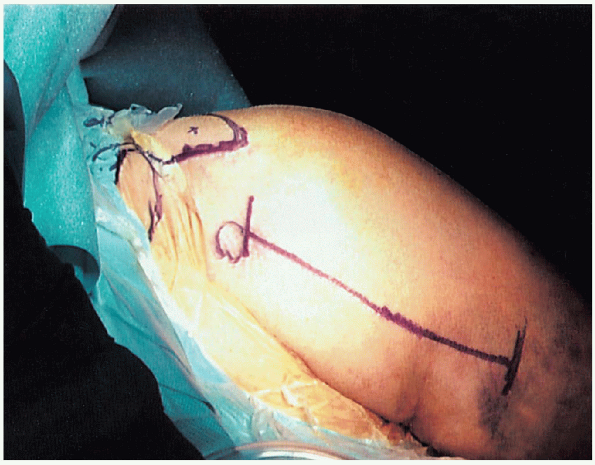 |
|
FIGURE 5-7.
The deltopectoral incision begins just lateral to the tip of the coracoid process and extends distally and laterally to the insertion of the deltoid. |
P.57
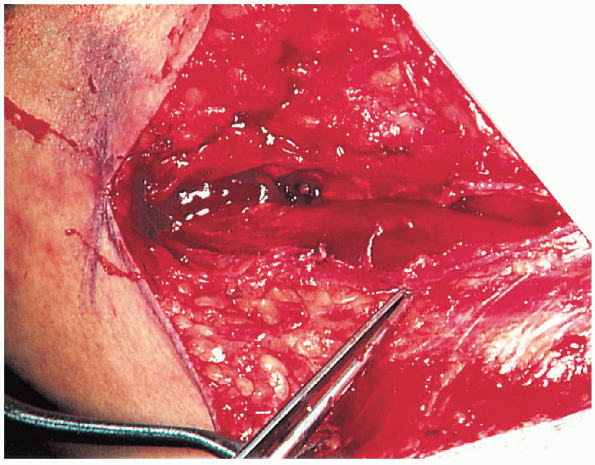 |
|
FIGURE 5-8. Identification of the cephalic vein, as indicated by the forceps.
|
PROCEDURE
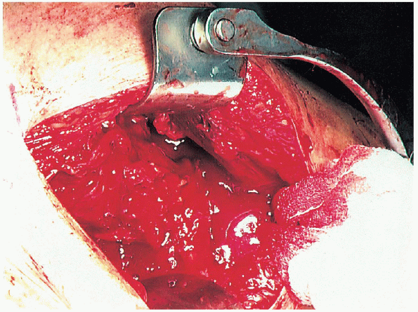
The biceps tendon is identified and tagged with a suture or Penrose drain. ![image]() The
The
biceps tendon provides an orientation to the greater and lesser
tuberosities. The lesser tuberosity is located medial to the biceps
tendon and the greater tuberosity is located superiorly and laterally.![image]()
Once located, the biceps tendon is followed up to the bicipital groove
and rotator interval, which is incised to the glenoid rim if the
fracture displacement has not already accomplished this. Dividing the
rotator interval enhances exposure and fragment mobilization.
Thebiceps tendon provides an orientation to the greater and lesser
tuberosities. The lesser tuberosity is located medial to the biceps
tendon and the greater tuberosity is located superiorly and laterally.
Once located, the biceps tendon is followed up to the bicipital groove
and rotator interval, which is incised to the glenoid rim if the
fracture displacement has not already accomplished this. Dividing the
rotator interval enhances exposure and fragment mobilization.
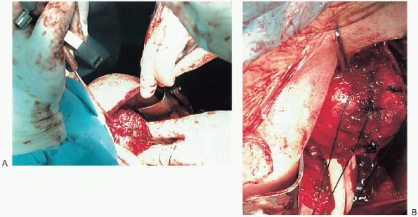
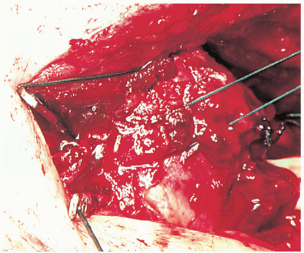
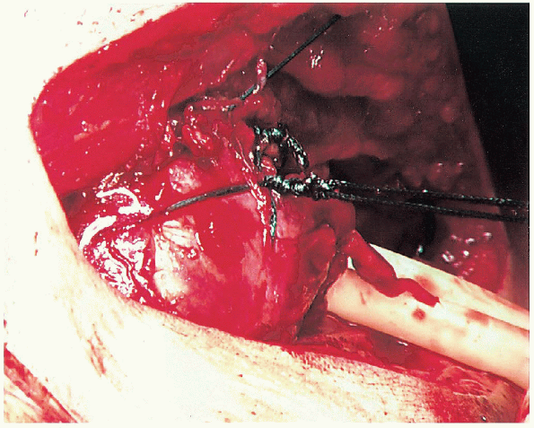
The displaced tuberosity is then mobilized with heavy nonabsorbable suture at the tendon insertion site (Fig. 5-10). ![image]() This
This
incorporates the stronger rotator cuff tendon rather than placing the
suture through what is usually the osteoporotic bone of the tuberosity
where it may easily cut out. The greater tuberosity fragment is
usually displaced superiorly into the subacromial space if the
supraspinatus is involved or posteriorly if the infraspinatus or teres
minor is the primary deforming force. The head and attached tuberosity
are mobilized with skin hooks and sutures at the bone tendon interface.
The fracture site is curetted and irrigated. The three fragments are
reduced to two by securing the displaced tuberosity to the head and
intact tuberosity via heavy nonabsorbable suture (Fig. 5-11).
Thisincorporates the stronger rotator cuff tendon rather than placing the
suture through what is usually the osteoporotic bone of the tuberosity
where it may easily cut out. The greater tuberosity fragment is
usually displaced superiorly into the subacromial space if the
supraspinatus is involved or posteriorly if the infraspinatus or teres
minor is the primary deforming force. The head and attached tuberosity
are mobilized with skin hooks and sutures at the bone tendon interface.
The fracture site is curetted and irrigated. The three fragments are
reduced to two by securing the displaced tuberosity to the head and
intact tuberosity via heavy nonabsorbable suture (Fig. 5-11).
 |
|
FIGURE 5-9. Use of a self-retainer to retract the conjoined tendon and the pectoralis major medially and the deltoid laterally.
|
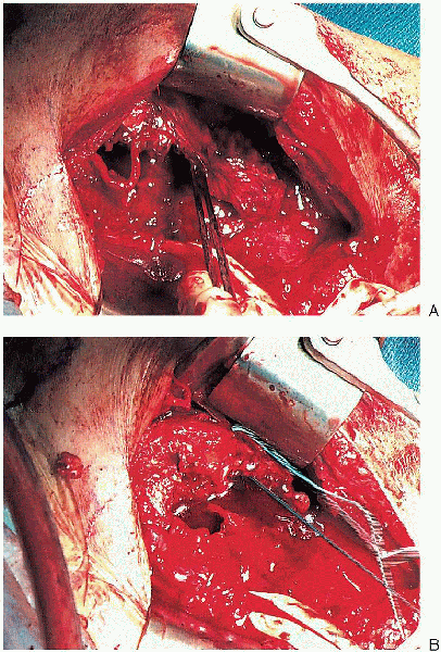 |
|
FIGURE 5-10. Mobilization of the displaced greater tuberosity (A) and placement of the nonabsorbable sutures at the tendon insertion site (B).
|
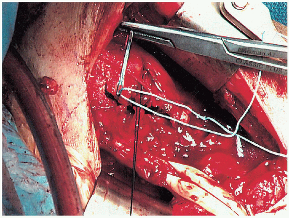
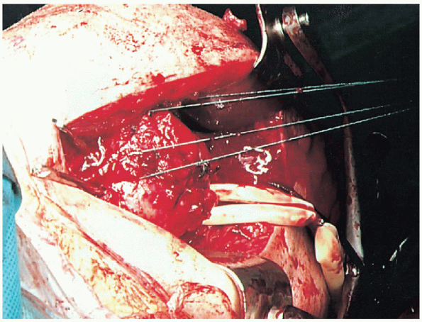
The displaced surgical neck fracture is exposed, the
humeral shaft and head is mobilized, and the fracture site is curetted.
A heavy suture is placed into the posterior aspect of the rotator cuff
for manipulation of the humeral head fragment. Drill holes are placed
in the humeral shaft fragment, 1 to 2 cm distal to the surgical neck
fracture on either side of the bicipital groove (Fig. 5-12). Heavy sutures are
P.58
passed through these drill holes; they will be used to provide a tension band after flexible nail insertion. Eighteen-gauge
wire may be substituted for heavy nonabsorbable suture; however,
although it provides greater immediate stability, it is more difficult
to handle and carries the risk of breakage and migration, which can
irritate the subacromial space.
 |
|
FIGURE 5-11. Stabilization of the greater tuberosity to the humeral head and intact tuberosity using heavy nonabsorbable suture.
|
The humeral head is reduced to the humeral shaft.
Fracture reduction is obtained by forward elevation of the humeral
shaft while gently pulling on the sutures controlling the proximal
fragment. The fracture is then impacted and the arm is extended while
maintaining tension on the sutures to prevent loss of reduction. Placement
of tension on the sutures placed through the posterior rotator cuff
extends the proximal fragment while the arm is extended and prevents
apex anterior angulation.
 |
|
FIGURE 5-12. Passage of heavy suture through the drill holes.
|
 |
|
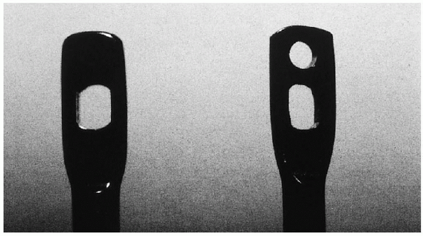
FIGURE 5-13. Modification of the Ender nail with placement of an additional hole above the slot.
|
Once adequate reduction is achieved, fixation is
accomplished using a combination of tension band suture and flexible
intramedullary nails. Ender nails (3.5 mm) are superior to straight
rods or pins such as Rush rods because they afford three-point
fixation, which enhances rotational stability. Furthermore, with use of
Ender nails, one can place a figure-of-eight suture or wire through the
eyelet to prevent proximal migration and impingement that often occurs
with nonfenestrated straight rods. However, the slot of the Ender nail
is long and a significant amount of metal may still protrude
proximally. Therefore, the nail can be modified with placement of an
additional hole above the slot (Fig. 5-13).
This allows for deeper insertion of the nail into the humeral head
placing the tip well below the rotator cuff tendon. The addition of the
tension band configuration with intramedullary nails has been found to
add even greater longitudinal and rotational stability over that of
either tension banding or intramedullary nailing alone.
While
maintaining reduction, small longitudinal incisions are made at the
insertion of the rotator cuff fibers into the greater and lesser
tuberosities. The two Ender nails are inserted
through the anterior and posterior aspect of the greater tuberosity in
two-part surgical neck fracture; one Ender nail is inserted through the
greater tuberosity and one through the lesser tuberosity and humeral
head in three-part fractures. An awl or drill bit is used to
penetrate the bone. The posterior nail is best placed initially because
levering on this partially inserted nail will aid in holding the
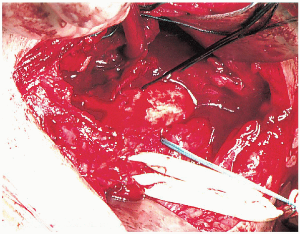
reduction and preventing the humeral head from falling posteriorly (Fig. 5-14).![image]() The second nail is then inserted 1.0 to 1.5 cm anterior to the first Ender nail (Fig. 5-15). It
The second nail is then inserted 1.0 to 1.5 cm anterior to the first Ender nail (Fig. 5-15). It
is best to use nails of different lengths to prevent the possibility of
a distal stress riser. Nails between 22 and 27 cm in length are
generally adequate. Before completely burying the nails, the
previously placed suture is placed through the eyelets of the nails,
passing deep to the rotator cuff between the two nails (Fig. 5-16). The nails are impacted below the rotator cuff, and the suture tied in a figure-of-eight manner (Fig. 5-17); this helps to prevent proximal nail migration. Before tying the suture, the fracture reduction is evaluated.
maintaining reduction, small longitudinal incisions are made at the
insertion of the rotator cuff fibers into the greater and lesser
tuberosities. The two Ender nails are inserted
through the anterior and posterior aspect of the greater tuberosity in
two-part surgical neck fracture; one Ender nail is inserted through the
greater tuberosity and one through the lesser tuberosity and humeral
head in three-part fractures. An awl or drill bit is used to
penetrate the bone. The posterior nail is best placed initially because
levering on this partially inserted nail will aid in holding the
reduction and preventing the humeral head from falling posteriorly (Fig. 5-14).
The second nail is then inserted 1.0 to 1.5 cm anterior to the first Ender nail (Fig. 5-15). Itis best to use nails of different lengths to prevent the possibility of
a distal stress riser. Nails between 22 and 27 cm in length are
generally adequate. Before completely burying the nails, the
previously placed suture is placed through the eyelets of the nails,
passing deep to the rotator cuff between the two nails (Fig. 5-16). The nails are impacted below the rotator cuff, and the suture tied in a figure-of-eight manner (Fig. 5-17); this helps to prevent proximal nail migration. Before tying the suture, the fracture reduction is evaluated.
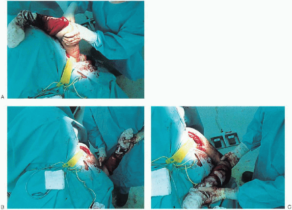
Once the figure-of-eight is secured, range of shoulder motion and fixation stability are assessed to carefully guide
P.59
the postoperative rehabilitation without stressing the repair (Fig. 5-18).
The rotator cuff incisions and deltopectoral interval are closed,
usually over suction drainage. A sterile dressing is applied and the
upper extremity is placed in a sling.
 |
|
FIGURE 5-14.
Insertion of the first Ender nail. The arm is extended with the fracture held reduced while the Ender nail is placed posterior in the proximal fragment (A and B). |
 |
|
FIGURE 5-15. Placement of the second Ender nail.
|
 |
|
FIGURE 5-16.
Before completely burying the nails, the previously placed suture is placed through the eyelets of the nails, passing deep to the rotator cuff between the two nails. |
 |
|
FIGURE 5-17. The nails are impacted below the rotator cuff, and the suture tied in a figure-of-eight manner.
|
P.60
 |
|
FIGURE 5-18.
Once the figure-of-eight is secured, range of shoulder motion and fixation stability are assessed to carefully guide the postoperative rehabilitation without stressing the repair (A to C). |
 |
|
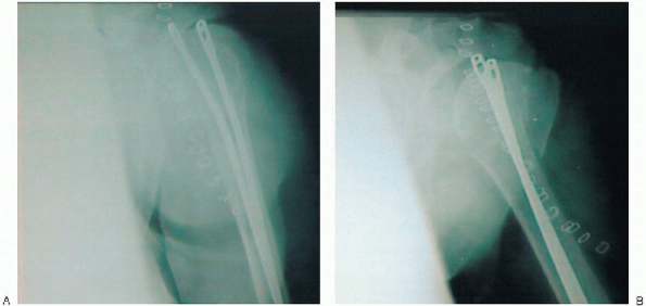
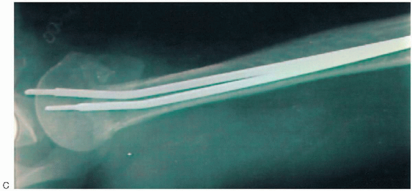
FIGURE 5-19. Intraoperative anteroposterior view of the shoulder with the humerus in internal rotation (A), external rotation (B), and axillary (C).
|
P.61
 |
|
FIGURE 5-19. (continued).
|
It is very important to obtain a complete set of radiographs in the operating room (Fig. 5-19).
This includes an AP view of the shoulder with the humerus in internal
rotation (on the chest) and maximum external rotation as defined by the
intraoperative assessment. An axillary view is also obtained.
This includes an AP view of the shoulder with the humerus in internal
rotation (on the chest) and maximum external rotation as defined by the
intraoperative assessment. An axillary view is also obtained.
POSTOPERATIVE PROTOCOL
On the first postoperative day, the patient is started
on a rehabilitation program that consists of active range of motion of
the elbow, wrist, and hand and passive range of motion of the shoulder.
External rotation is limited based on the intraoperative evaluation.
This is important to avoid any excess stress on the fracture repair
that may compromise healing. Internal rotation is allowed to the chest.
These exercises are continued for the first 6 to 8 weeks. Radiographs
are obtained approximately 2 weeks following surgery to confirm the
fracture position. Additional radiographs are obtained at 6 to 8 weeks
following surgery. If fracture healing is sufficient, the sling is
discontinued and an active range-of-motion program is begun. The
patient is encouraged to use the involved upper extremity for
activities of daily living. Passive range of motion is continued with
gentle stretching to increase the overall range. At 8 weeks following
surgery, isometric deltoid and internal and external rotator
strengthening exercises are begun. Vigorous strengthening exercises are
not begun until active forward elevation of at least 90 degrees is
obtained. Our experience has shown that patients can expect continued
recovery during the first year following surgery, although most
recovery occurs during the first 6 months.
SUGGESTED READINGS
Bigliani LU. Fractures of the humerus. In: Rockwood CA, Matsen FA III, eds. The shoulder. Philadelphia: WB Saunders, 1990: 278-334.
Cuomo F, Flatow EL, Maday MG, et al. Open reduction and internal fixation of two- and three-part displaced surgical neck fractures of the proximal humerus. J Shoulder Elbow Surg 1992; 1: 287-295.
Hawkins RJ, Angelo RL. Displaced proximal humeral fractures: selecting treatment, avoiding pitfalls. Orthop Clin North Am 1987; 18: 421-431.
Hawkins RJ, Bell RH, Gurr K. The three-part fracture of the proximal part of the humerus: operative treatment. J Bone Joint Surg Am 1986; 68A: 1410-1414.
Hawkins RJ, Kiefer GN. Internal fixation techniques for proximal humeral fractures. Clin Orthop 1987; 223: 77-85.
Kristiansen B, Christensen SW. Plate fixation of proximal humeral fractures. Acta Orthop Scand 1986; 57: 320-323.
Lentz W, Meuser P. The treatment of fractures of the proximal humerus. Arch Orthop Trauma Surg 1980; 96: 283-285.
Moda SK, Chadha NS, Sangwan SS, et al. Open reduction and fixation of proximal humeral fractures and fracture-dislocation. J Bone Joint Surg Br 1990; 72B: 1050-1052.
Mouradian WH. Displaced proximal humeral fractures: seven years’ experience with a modified Zickel supracondylar device. Clin Orthop 1986; 212: 209-218.
Neer CS II. Displaced proximal humeral fractures: part I. Classification and evaluation. J Bone Joint Surg Am 1970; 52A: 1077-1089.
Neer CS II. Displaced proximal humeral fractures: part II. Treatment of three-part and four-part displacement. J Bone Joint Surg Am 1970; 52A: 1090-1103.
Norris TR. Fractures of the proximal humerus and dislocations of the shoulder. In: Browner, BD, Jupiter JB, Levine AM, et al., eds. Skeletal trauma. Philadelphia: WB Saunders, 1992: 1201-1290.
Paavolainen P, Bjorkenheim JM, Slatis P, et al. Operative treatment of severe humeral fractures. Acta Orthop Scand 54: 374-379.
Pankovich AM. Update 1987—flexible intramedullary nailing of long bone fractures: a review. J Orthop Trauma 1987; 1(1): 78-95.
Sturzenegger M, Fornaro E, Jakob RP. Results of surgical treatment of multifragmented fractures of the humeral head. Arch Orthop Trauma Surg 1982; 100: 249-259.
Weseley MS, Barenfeld PA, Eisenstein AL. Rush pin intramedullary fixation for fractures of the proximal humerus. J Trauma 1977; 17(1): 29-37.