
Editors: Berquist, Thomas H.
Title: Musculoskeletal Imaging Companion, 2nd Edition
Copyright ©2007 Lippincott Williams & Wilkins
> Table of Contents > Chapter 16 – Orthopedic Appliances and Prostheses
Chapter 16
Orthopedic Appliances and Prostheses
Thomas H. Berquist
Internal Fixation Systems
Key Facts
-
There are numerous internal fixation devices, most with a specific indication or anatomic design.
-
Selection of the appropriate system
depends on the indication (e.g., fracture, neoplasms), patient’s
clinical status, and surgical preference. -
Common devices and indications are summarized as follows:
Device Indication/Application Cortical screws Threaded entire length. Should penetrate opposite cortex by 1 to 2 mm. Often used with plates. Cancellous screws Wider threads, may be partially threaded. Most commonly used in cancellous bone or metaphysis. Interference screws Fully threaded with no heads. Used to fix bone plugs or tendon grafts. Soft tissue anchors Used for soft tissue attachment to bone. Dynamic compression screws Allow bones to impact. Usually used with a side plate. Plates Common in variable lengths and configurations. Straight—diaphyseal fixation. Special—metaphyseal and epiphyseal fixation. Intramedullary fixation Stabilize fracture without
exposing fracture site. Most commonly used in humerus, tibia, and
femur. Static configuration—screws in both ends of device. Dynamic
configuration—screws in one end only. -
Complications of internal fixation:
-
Loosening and screw pullout
-
Soft tissue irritation from protruding screws
-
Stress risers from screw holes
-
Instrument failure
-
Infection
-
Loss of reduction
-
Delayed union, malunion, or nonunion
-
-
Imaging of fixation devices can be easily
accomplished using serial radiographs. Thin-section computed tomography
(CT) with reformatting in the coronal and sagittal planes is useful for
evaluating healing and delayed or nonunion. Detection of infection may
require radionuclide scans or magnetic resonance imaging (MRI).
P.972
P.973
 |
|
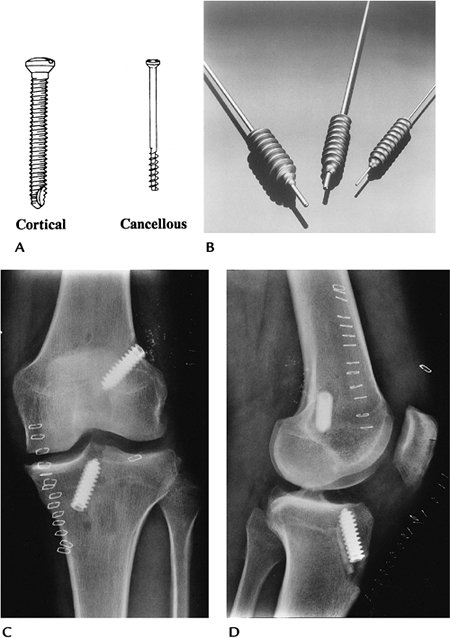
FIGURE 16-1 Screws. (A) Fully threaded cortical and partially threaded cancellous screws (courtesy of Zimmer, Warsaw, IN). (B) Interference screws. Anteroposterior (AP) (C) and lateral (D)
radiographs of the knee after anterior cruciate ligament repair. The interference screws secure the bone plugs at the ends of the tendon graft. |
P.974
 |
|
FIGURE 16-2 Soft tissue anchors. (A) Revo cancellous screw and suture for anchoring soft tissues (courtesy of Linvatec, Largo, FL). (B) Shoulder radiograph after rotator cuff repair using soft tissue anchors. One of the anchors (arrow) has pulled out.
|
P.975
 |
|
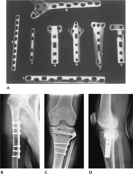
FIGURE 16-3 Plate and screw fixation. (A)
Straight dynamic compression plates (1), one-third tubular plate (3), T-buttress (4), and L-buttress plates (5), cloverleaf plate (olecranon fixation) (6), spoon plate (7), and condylar buttress plate (distal femur) (8). (B) Midhumeral fracture internally fixed with a dynamic compression plate and cortical screws. (C,D) Tibial plateau fracture reduced using a T-buttress plate, and proximal cancellous (arrowheads) and distal cortical screws. |
P.976
 |
|
FIGURE 16-4 Dynamic compression screw. (A) Dynamic compression screws with side plates of different lengths and femoral neck angles. (B) Intertrochanteric fracture reduced using a dynamic hip screw and four-hole side plate with cortical screws.
|
P.977
 |
|
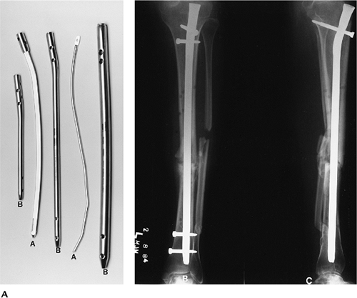
FIGURE 16-5 Intramedullary nails. Solid (A) and hollow (B) intramedullary nails with proximal and distal holes for screws. AP (B) and lateral (C)
radiographs of a midtibial fracture with static (screws at both ends) intramedullary nail fixation. The fracture margins are sclerotic (arrow) because of delayed union. |
 |
|
FIGURE 16-6 Implant failure. AP radiograph of the right femur with fracture of the side plate and several screws.
|
P.978
Suggested Reading
Behrens F. A primer of fixation devices and configurations. Clin Orthop 1989;24:5–14.
Berquist TH, Broderson MP. General orthopedic fixation devices. In: Berquist TH, ed. Imaging atlas of orthopedic appliances and prostheses. New York: Raven Press; 1995:45–108.
P.979
External Fixation Systems
Key Facts
-
External fixation systems, common in
numerous configurations, can be designed for specific anatomic regions
and may be designed to allow joint motion. -
External fixation systems may be unilateral, ring configuration, rectangular, or partially circumferential.
-
There are three major goals for external fixation systems:
-
Allow access to the injured area
-
Avoid injury to vital structures
-
Meet the mechanical demands of the injury
-
-
Advantages of external fixation include
-
Limited soft tissue injury with insertion
-
Pins can be used as handles to reduce fractures
-
Improved wound access
-
Early motion of involved joints
-
-
Complications of external fixation systems include
-
Pin tract infection
-
Loss of reduction
-
Soft tissue or neural injury
-
-
Imaging of fixation pins may require
fluoroscopically positioned spot views. Serial radiographs are useful
for monitoring fracture position.
P.980
 |
|
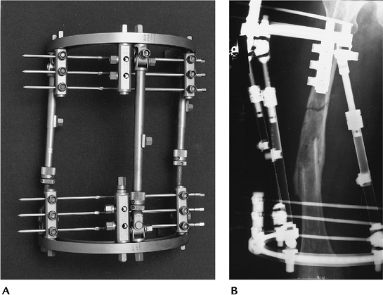
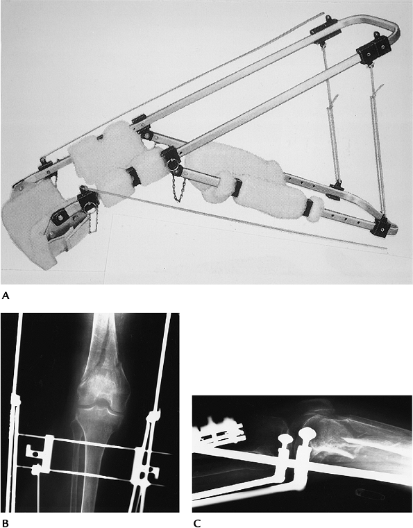
FIGURE 16-7 Fisher external fixation. (A) Fisher fixation system. (B) Radiograph of a refractured femur reduced using Fisher external fixation.
|
P.981
 |
|
FIGURE 16-8 Colles fracture with external fixation. The system (arrowhead) allows wrist motion. Posteroanterior PA (A) and lateral (B) radiographs showing external fixation of a Colles fracture. Note the proximal pin (open arrow) has fractured the distal cortex.
|
Suggested Reading
Behrens F. General theory and principles of external fixation. Clin Orthop 1989;241:15–23.
Berquist TH, Broderson MP. General orthopedic fixation devices. In: Berquist TH, ed. Imaging atlas of orthopedic appliances and prostheses. New York: Raven Press; 1995:45–108.
P.982
Traction
Key Facts
-
Traction can be used for brief periods to
assist with fracture reduction or for longer periods to improve
fragment position before more definitive therapy. -
Traction devices use smooth or threaded pins.
-
Traction is most commonly used for distal
femoral fractures. Certain other extremity fractures, such as the
humerus, also may be treated with traction. -
Traction pins for lower extremity
injuries can be placed in the distal femur, proximal tibia, or
calcaneus. Calcaneal traction carries a higher incidence of infection. -
Imaging of injuries treated in traction
requires serial studies to monitor position of fragments (ensures
proper weight on traction device). Two views at 90 degrees taken at the
bedside usually are sufficient. -
Complications include
-
Pin tract infection
-
Pin loosening
-
Shortening or rotation (too little weight)
-
Soft tissue interposition when fragments are too distracted (too much weight)
-
P.983
 |
|
FIGURE 16-9 Traction. (A) Thomas splint for lower extremity traction (courtesy of Zimmer, Warsaw, IN). AP (B) and lateral (C) radiographs of a supracondylar femur fracture treated in traction. There are two threaded traction pins in the upper tibia.
|
Suggested Reading
Berquist TH, Brodersen MP. General orthopedic fixation devices. In: Berquist TH, ed. Imaging atlas of orthopedic appliances and prostheses. New York: Raven Press; 1995:45–108.
P.984
Spinal Instrumentation: Long Segment Instrumentation
Key Facts
-
The most common indication for long segment spinal instrumentation is scoliosis.
-
Preoperative imaging, measurement techniques, and cause were discussed in Chapter 3.
-
Both anterior and posterior instrumentations have been used. The latter is more common.
-
Anterior instrumentation (shorter segments):
-
Dwyer system: titanium cable, staples, and cancellous screws
Advantages Excellent primary curve correction Disadvantages Secondary curve response uncertain; cable fracture; kyphotic effect -
Zielke system: modified Dwyer; cable replaced with steel rod placed through slotted cancellous screws
-
Texas Scottish Rite Hospital system: similar to Zielke
-
-
Posterior instrumentation systems use
rods (compression and/or distraction), hooks, cross links (improve
rotational stability), and sublaminar wires. -
Complications of scoliosis instrumentation include
-
Loss of correction
-
Rod fracture
-
Hook displacement
-
Screw pullout
-
Pseudarthrosis
-
Infection
-
Neurologic injury
-
-
Imaging of complications
-
Most instrument failure complications can be detected on serial radiographs.
-
Diagnosis of infection may require radionuclide scans and fluoroscopically guided aspirations for culture.
-
Pseudarthrosis may be difficult to identify unless motion radiographs show obvious changes.
-
Radionuclide scans (>9 months after surgery), CT, or MRI may be required to detect pseudarthrosis.
-
P.985
 |
|
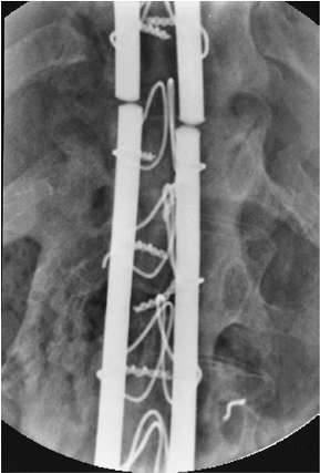
FIGURE 16-10 Posterior long segment instrumentation. (A,B) Luque instrumentation. (A) Smooth Luque rods, sublaminar wires, and proximal and distal “H” bars (arrowheads). (B) PA radiograph with multiple Luque rods, sublaminar wires, and proximal and distal cross links (arrowheads). (C,D) Cotrel-Dubousset instrumentation. (C) Diamond-point surface rods with hooks and cross links. (D) PA radiograph after Cotrel-Dubousset instrumentation.
|
P.986
 |
|
FIGURE 16-11 Rod fracture. AP radiograph of fracture of Luque rods caused by pseudarthrosis.
|
Suggested Reading
Dawson EG, Clader TJ, Bassett LW. A comparison of different methods used to diagnose pseudarthrosis. J Bone Joint Surg 1985;67A:1153–1159.
Ohashi K, Bennet DL, Restrepo JM, et al. Orthopedic hardware complications diagnosed with multidetector row CT. Radiology 2005;237:570–577.
P.987
Spinal Instrumentation: Short Segment Instrumentation
Key Facts
-
Short segment instrumentation is commonly used for trauma, degenerative disease, spondylolisthesis, and neoplasms.
-
Surgical approaches may be anterior, posterior, or combined.
-
Common instrumentation includes interbody
cages, disc replacement, plates, rods, rectangles, pedicle screws,
vertebral body screws, and bone grafting. -
Preoperative imaging varies with the indication:
Indication Imaging Technique Degenerative disease/spondylolisthesis Routine radiographs
Flexion-extension views (measure subluxation, stability)
CT—pedicle screw size
Discogram—confirm source of painTrauma Routine radiographs
CT—fragment position, pedicle screw size
MRI—neural injuryVertebral replacement Routine radiographs
CT—bone loss
MRI—soft tissue, neural involvement -
Complications of short segment instrumentation:
-
Instrument failure
-
Pedicle screw malposition
-
Displaced interbody devices
-
Pseudarthrosis
-
Neural injury
-
Adjacent disc or facet disease
-
-
Postoperative imaging varies with the
suspected complication. Most complications can be detected on serial
radiographs. Imaging of other complications can be approached similar
to long segment instrumentation complications.
P.988
 |
|
FIGURE 16-12 Trauma: fracture/dislocation at T12. AP (A) and lateral (B)
radiographs showing reduction using Isola rods, with pedicle screws at L1 and L2 and hooks proximally. Generally, fixation should include two to three vertebrae above and below the injury. |
P.989
 |
|
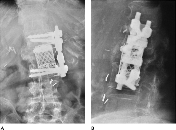
FIGURE 16-13 Vertebral body replacement. AP (A) and lateral (B) radiographs showing a titanium interbody cage and anterior vertebral body screws and rods (Kenada device) for fixation.
|
P.990
 |
|
FIGURE 16-14 Pedicle screw complications. Axial CT image (A) demonstrating good positioning of pedicle screws in the pedicle and body (thick arrows) of L5. AP radiograph after myelography (B) demonstrates rod and pedicle screw instrumentation from L3 to the sacrum. Coronal CT image (C) shows the lower right pedicle screw extending into the foramen (arrow).
|
P.991
 |
|
FIGURE 16-15 AP (A) and lateral (B)
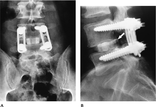
radiographs with plate and pedicle screw instrumentation posteriorly and a bone graft in the L4–5 disc. The graft has displaced posteriorly (arrow) into the spinal canal resulting in neurologic deficit. |
Suggested Reading
Togawa
D, Bauer TW, Lieberman IH, et al. Lumbar intervertebral body fusion
cages: Histologic evaluation of clinically failed cages retrieved from
humans. J Bone Joint Surg 2004;86A:70–79.
D, Bauer TW, Lieberman IH, et al. Lumbar intervertebral body fusion
cages: Histologic evaluation of clinically failed cages retrieved from
humans. J Bone Joint Surg 2004;86A:70–79.
Tropiano P, Huang RC, Girardi FP, et al. Lumbar total disc replacement. J Bone Joint Surg 2006;88A:50–64.
West JL, Ogilvie JW, Bradford DS. Complications of the variable plate pedicle screw fixation. Spine 1991;16:576–579.
P.992
Shoulder Arthroplasty
Key Facts
-
Glenohumeral joint replacement is the technique of choice for patients with painful articular disorders (Table 16-1) who do not respond to conservative therapy.
-
Prognosis and selection of technique
(total joint replacement vs. hemiarthroplasty) varies with the extent
of bone, joint, and soft tissue involvement. New reverse shoulder
components are now used for patients with severe rotator cuff
deficiency. -
Preoperative evaluation includes clinical scoring for pain, function, and range of motion plus imaging of the involved shoulder.
-
Radiographs: AP, Neer view, axillary
-
CT: Bone stock, especially glenoid
-
MRI: Soft tissue involvement
-
-
Component and procedure selection:
-
Constrained system: rotator cuff
mechanism loss and inadequate soft tissue support; high incidence of
loosening; not commonly used today -
Nonconstrained system: adequate soft tissue support
-
Hemiarthroplasty (humeral component only): avascular necrosis of the humeral head; normal glenoid
-
-
Postoperative imaging/complications:
-
Complications of shoulder arthroplasty are summarized in Table 16-2. Imaging varies with suspected complication.
-
|
TABLE 16-1 SHOULDER ARTHROPLASTY INDICATIONS
|
|
|---|---|
|
P.993
|
TABLE 16-2 SHOULDER ARTHROPLASTY COMPLICATIONS
|
||||||||||||||||||||
|---|---|---|---|---|---|---|---|---|---|---|---|---|---|---|---|---|---|---|---|---|
|
| Complication | Imaging Technique |
|---|---|
| Glenoid loosening | Serial fluoroscopically positioned spot views |
| Humeral component loosening (>2-mm lucent lines) | Serial radiographs |
| Humeral component subsidence | Serial radiographs |
| Subluxation/dislocation | Serial radiographs |
| Neural injury | MRI |
| Infection | Radionuclide scans or MRI |
| Humeral fracture | Serial radiographs |
P.994
 |
|
FIGURE 16-16 Shoulder arthroplasty components. (A) Fenlin total shoulder system. Cobalt-chromium-molybdenum humeral components with three proximal fins and holes (arrowheads)
for soft tissue attachment. Modular heads are on top and barbed keel glenoid components are below (courtesy of Zimmer, Warsaw, IN). (B) Total shoulder II with four stem configurations and an all-polyethylene glenoid component (curved arrow). (Courtesy of Zimmer, Warsaw, IN.) |
P.995
 |
|
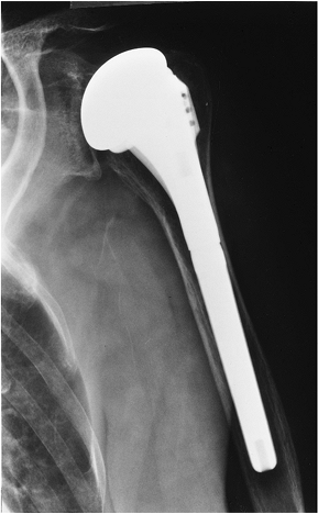
FIGURE 16-17 Hemiarthroplasty. AP radiographs showing a modular DePuy humeral component. There is no glenoid component.
|
P.996
 |
|
FIGURE 16-18 Delta III inverted shoulder prosthesis for patients with severe rotator cuff deficiency. (A) Photograph of the components with the ball on the glenoid side (DePuy France, Saint Priest CEDEX, France). (B) AP radiograph after placement of a Delta system.
|
P.997
 |
|
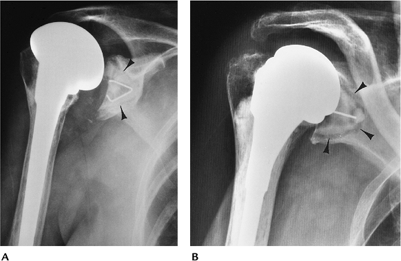
FIGURE 16-19 Glenoid component loosening. (A) Fluoroscopically positioned AP radiograph showing a cemented glenoid component (arrowheads) with no lucency. (B) Fluoroscopically positioned radiograph showing wide lucent lines at the bone–cement interface (arrowheads) of the polyethylene glenoid component caused by loosening.
|
P.998
 |
|
FIGURE 16-20
Loose, infected humeral component. AP radiograph showing wide irregular lucency about the cement with a distal cement fracture (arrow) caused by loosening. There is diffuse periostitis and cortical destruction caused by infection. |
Suggested Reading
Craig EV. Total shoulder replacement. Orthopedics 1988;11:125–136.
Frankle
M, Siegal S, Pupello D, et al. The reverse shoulder prosthesis for
glenohumeral arthritis associated with severe rotator cuff deficiency. J Bone Joint Surg 2005;87A:1697–1705.
M, Siegal S, Pupello D, et al. The reverse shoulder prosthesis for
glenohumeral arthritis associated with severe rotator cuff deficiency. J Bone Joint Surg 2005;87A:1697–1705.
P.999
Elbow Arthroplasty
Key Facts
-
Elbow arthroplasty has evolved over the years as a procedure to relieve pain, improve motion, and increase stability.
-
Indications: rheumatoid arthritis, osteoarthritis, posttraumatic arthritis
-
Contraindications: paralysis, previous open wound infection, arthrodesis
-
Preoperative evaluation includes clinical
evaluation of pain, function, and range of motion (an arc of 30 to 130
degrees provides the necessary function), and imaging of bone and soft
tissue integrity.-
Radiographs: AP and lateral with sufficient humerus and forearm to select components
-
Stress views and flexion-extension views: baseline motion and stability
-
CT: evaluate bone stock and medullary width
-
MRI: soft tissue support
-
-
Component and procedure selection:
-
Constrained: hinged metal systems for significant loss of soft tissue support. Rarely used today.
-
Semiconstrained: May have a hinge and
polyethylene inserts that permit 5 to 10 degrees of axial rotation and
varus and valgus motion. -
Unconstrained: more anatomic. Requires good soft tissue support.
-
-
Postoperative imaging/complications:
Complications after elbow arthroplasty may not affect patient outcome.
Complications are related to the type of procedure, implant used, and
patient compliance (Table 16-3).-
Imaging approaches vary with the suspected complication.
TABLE 16-3 ELBOW ARTHROPLASTY COMPLICATIONSComplication Incidence Loosening Semi-constrained 1%–2% Constrained 23%–31% Instability 5%–18% Implant failure Component fracture 1% Linkage failure 3% Infection 1%–5% Ulnar nerve injury Permanent 2% Transient 22%–26% Cortex penetration (30% for revision systems) 5%–30% Triceps deficiency 5% Complication Imaging Technique Loosening (>2-mm lucent lines) Serial radiographs Instability Fluoroscopically positioned stress views Implant failure Serial radiographs Infection Radionuclide scans; joint aspiration Ulnar nerve injury MRI (metal artifact may degrade images) Triceps deficiency Clinical evaluation -
P.1000
 |
|
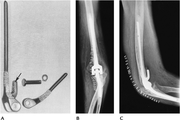
FIGURE 16-21 (A) Coonrad-Morrey elbow prosthesis with polyethylene hinge, beaded stems, and anterior extension on the humeral component (arrow). AP (B) and lateral (C) radiographs of a Coonrad-Morrey arthroplasty.
|
P.1001
 |
|
FIGURE 16-22 Loose implant. AP (A) and lateral (B) radiographs showing a grossly loose ulnar component caused by toggling.
|
Suggested Reading
Cooney WP. Elbow arthroplasty: Historical perspective and current concepts. In: Morrey BF, ed. The elbow and its disorders, 3rd ed. Philadelphia: WB Saunders; 2000:583–601.
Morrey BF. Complication of elbow replacement surgery. In: Morrey BF, ed. The elbow and its disorders, 3rd ed. Philadelphia: WB Saunders; 2000:667–677.
P.1002
Wrist Arthroplasty
Key Facts
-
Wrist arthroplasty procedures and implant development began shortly after the initial successes with hip arthroplasty.
-
Indications: Rheumatoid arthritis is the primary indication.
-
Contraindications: paralysis, heavy
activity, infection. Poor bone stock and previous arthrodesis are
relative contraindications. -
Preoperative evaluation includes degree
of pain, stability in flexion, extension, radial and ulnar deviation,
and range of motion. Imaging should include PA, lateral, and oblique
radiographs. Motion studies may serve as a baseline for the degree of
motion. CT may be used to evaluate bone stock. -
Component and procedure selection:
-
Constrained (trispheric): Prevents ulnar drift and dislocation. Higher incidence of loosening.
-
Swanson Silastic: Reduces forces across the component, thus decreasing the likelihood of loosening.
-
Meuli system: Requires resection of radial styloid, distal ulna, and proximal carpal row.
-
Volz prostheses: Allows 90 degrees of flexion and extension and 50 degrees of radioulnar deviation.
-
Anatomic designs (Biax; DePuy, Warsaw, IN) allow more normal wrist motion.
-
-
Postoperative imaging/complications: Complications are related to procedure, implant selection, and patient status (Table 16-4). Imaging approaches vary with complication. Silicone implants do not cause artifacts on magnetic resonance images.
P.1003
|
TABLE 16-4 WRIST ARTHROPLASTY COMPLICATION
|
||||||||||||||||||||||||||||||||||
|---|---|---|---|---|---|---|---|---|---|---|---|---|---|---|---|---|---|---|---|---|---|---|---|---|---|---|---|---|---|---|---|---|---|---|
|
P.1004
P.1005
 |
|
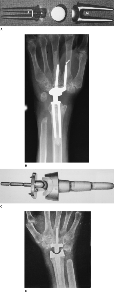
FIGURE 16-23 Wrist arthroplasty implants. (A)
Meuli implant. The distal cupped component is placed in the second and third metacarpals (M), and the proximal trunnion stems are in the radius (R). (From Beckenbaugh RD. Total joint arthroplasty: the wrist. Mayo Clin Proc 1979;54:513–515.
) (B) Radiograph of the Meuli prosthesis. The distal ulna was resected. Note the second metacarpal stem (arrow) is eroding the cortex. (C) A.M.C. wrist implant. (Courtesy of Howmedica, Rutherford, NJ.) (D) Radiograph of the A.M.C. implant. |
P.1006
 |
|
FIGURE 16-24 Wrist arthroplasty complications. (A) Loose Meuli metacarpal components with lucency around the second metacarpal stem and cortical breakthrough of the third. (B) Lateral radiograph demonstrating a dorsal dislocation.
|
Suggested Reading
Beckenbaugh RD. Arthroplasty of the wrist. In: Morrey BF, ed. Reconstructive surgery of the joints, 2nd ed. New York: Churchill Livingstone; 1996:387–410.
P.1007
Carpal and Thumb Arthroplasties
Key Facts
-
Severe pain and function loss at the
thumb base are common in women with osteoarthritis. Carpal bone
replacement is most common for the lunate and scaphoid. -
Indications:
-
Thumb: osteoarthritis, rheumatoid arthritis
-
Carpal: posttraumatic arthritis, osteoarthritis, avascular necrosis
-
-
Preoperative evaluation: Clinical
evaluation includes grip, pinch strength, stability, and imaging
features. Routine radiographs usually are adequate for evaluation. MRI
may be useful for avascular necrosis. -
Component and procedure selection:
-
Thumb: silicone replacement of thumb base with or without trapezium resection
-
Polyethylene and metal total joint replacement reserved for more severe disease.
-
Carpal: silicone carpal replacement
-
-
Postoperative imaging/complications:
Complications are similar to wrist arthroplasty, except for the common
problem of silicone-induced synovitis. Implant failures occur in up to
15% of patients. Imaging of complications generally is possible with
serial radiographs (Table 16-4). MRI with contrast is useful in patients with suspected silicone synovitis.
P.1008
 |
|
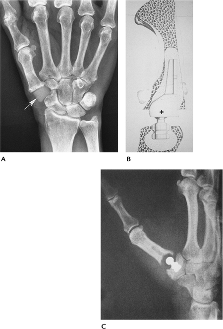
FIGURE 16-25 Thumb/carpal implants. (A) Radiograph of a medullary stem silicone trapezial implant (arrow). (B,C) Mayo trapeziometacarpal arthroplasty. The center of rotation (+) is at the base of the first metacarpal. (C) Radiograph of the implant in place. (From
Cooney WP, Linscheid RL, Ashew L. Total arthroplasty of the thumb trapeziometacarpal joint. Clin Orthop 1987;320:35–45.
) |
P.1009
 |
|
FIGURE 16-26 Silicone-induced osteolysis. (A) Radiograph of the thumb showing bone resorption (osteolysis) around the stem of the implant (arrows). (B) T2-weighted MRI in a different patient with fracture of the silicone implant (arrowhead) and synovitis (short arrow).
|
Suggested Reading
Cooney WP. Arthroplasty of the thumb axis. In: Morrey BF, ed. Reconstructive surgery of the joints, 2nd ed. New York: Churchill Livingstone; 1996:313–339.
Murray PM, Wood MB. The results of treatment of synovitis of the wrist induced by particles of silicone debris. J Bone Joint Surg 1998;80A:397–406.
P.1010
Metacarpophalangeal and Interphalangeal Arthroplasty
Key Facts
-
Metacarpophalangeal (MCP) and proximal
interphalangeal joint replacement procedures are designed to improve
function and stability and relieve pain. -
Indications: rheumatoid arthritis, posttraumatic arthritis, inflammatory arthropathies with deformities, and reduced function
-
Preoperative evaluation includes the
degree of pain, deformity, motion, and stability. Routine radiographs
generally are adequate for preoperative imaging. -
Component and procedure selection:
• MCP Silicone or metal-polyethylene implants • Proximal interphalangeal Metal-polyethylene hinge or single- or double-stemmed silicone implants -
Postoperative imaging/complications:
Patients are evaluated for improved function and pain relief.
Complications are similar to wrist arthroplasty and vary with the type
of implant (Table 16-5).-
Routine radiographs usually are adequate
for evaluating common complications. MRI and CT are useful for subtle
osseous and soft tissue changes.
-
|
TABLE 16-5 METACARPOPHALANGEAL AND PROXIMAL INTERPHALANGEAL ARTHROPLASTY COMPLICATIONS
|
||||||||||||||||||||||||
|---|---|---|---|---|---|---|---|---|---|---|---|---|---|---|---|---|---|---|---|---|---|---|---|---|
|
||||||||||||||||||||||||
P.1011
 |
|
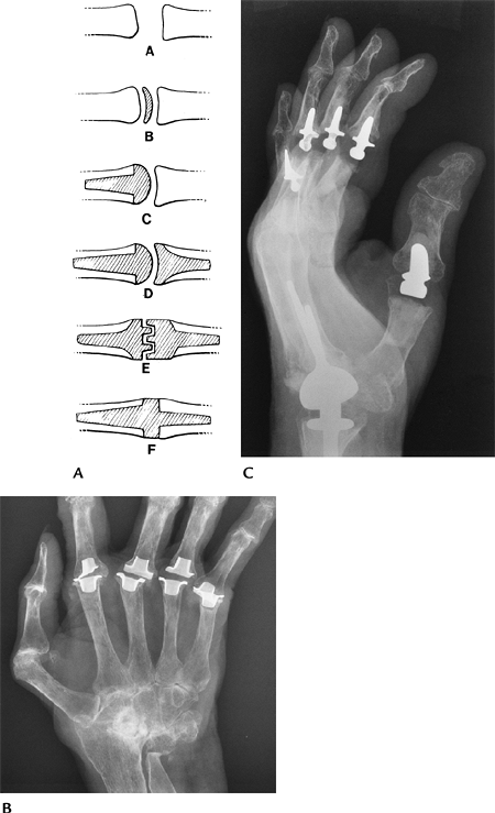
FIGURE 16-27 MCP and proximal interphalangeal implants. (A)
Categories of hand implants: A, resection arthroplasty; B, interposition arthroplasty; C, condylar replacement; D, ball-and-socket configuration; E, interlocking hinges; F, flexible Silastic implant. (From Berquist TH. Imaging atlas of orthopedic appliances and prostheses. New York: Raven Press; 1995.
) (B) AP radiograph showing Silastic MCP implants with metal grommets to reduce wear. (C) Lateral radiograph showing Meuli wrist and Mayo interphalangeal joint implants (metal and plastic hinge). |
P.1012
 |
|
FIGURE 16-28 Complications. (A) PA radiograph showing heterotopic bone (white arrow) and lucency about the distal stem (black arrow) caused by loosening. (B) Failed double-stem silicone implant with erosion through the cortex and a large granuloma (arrow).
|
Suggested Reading
Carter PR, Benton LJ, Dysert PA. Silicone rubber carpal implant: A study of the incidence of late osseous complications. J Hand Surg 1986;11A:639–644.
Linscheid RL, Dobyns JH. Total joint arthroplasty: The hand. Mayo Clin Proc 1979;54:516–526.
Theumann
NH, Pessis E, Lecompte M, et al. MR imaging of the metacarpophalangeal
joints of the fingers: Evaluation of 38 patients with chronic
disability. Skel Radiol 2005;34:210–216.
NH, Pessis E, Lecompte M, et al. MR imaging of the metacarpophalangeal
joints of the fingers: Evaluation of 38 patients with chronic
disability. Skel Radiol 2005;34:210–216.
P.1013
Hip Arthroplasty
Key Facts
-
Hip arthroplasty has evolved over the
last 40 years and now is performed on more than 200,000 patients in the
United States each year. -
Indications: Hip arthroplasty generally
is reserved for patients aged more than 60 years with painful
arthrosis. Implant survival is superior in older patients. Implants
survived 25 years in 87% of patients treated at more than 60 years of
age, but lasted 25 years in only 62% of patients treated at 40 to 50
years of age. Common indications include osteoarthritis, rheumatoid
arthritis, traumatic arthritis, avascular necrosis, and congenital hip
dis- orders. -
Preoperative evaluation includes the
degree of pain, range of motion, and function. Imaging includes AP and
lateral radiographs, which should include the upper third of the femur.
CT is useful for evaluating bone stock in the acetabular region. MRI is
useful in patients with avascular necrosis (5% have acetabular
involvement) and to evaluate soft tissue support. Preoperative
anesthetic injection to confirm the hip as the source of pain is useful
in selected cases. -
Component and procedure selection:
-
Unipolar implants: Reserved for treatment of fractures or femoral head abnormalities.
-
Bipolar implants: Improved function and
decreased acetabular wear compared with older unipolar designs. Used
for avascular necrosis and femoral neck fractures. -
Total hip systems: Most are modular
today, with variations in head size, acetabular configuration, presence
or absence of femoral collar, and variable femoral length. Metal
alloys, polyethylene liners, and ceramic components are available.
Components are designed to be used with or without cement.
-
-
Normal postoperative features: AP and
lateral radiographs provide baseline data on position of acetabular and
femoral components.-
Acetabular components: Acetabular
component should be angled approximately 45 degrees (range 35–55
degrees) on the AP view and 0 to 15 degrees of anteversion on the
lateral view. Evaluation of the metal–bone (uncemented) or bone–cement
(cemented) interfaces is divided into three zones to evaluate lucent
lines (Fig. 16-30A). -
Femoral component: Femoral component
should be in neutral to valgus position. Seven zones are configured for
evaluating the metal–bone or bone–cement interfaces (Fig. 16-29A).
For uncemented components, the femoral stem should be within 1 mm of
the cortex (~40% of stem within 1 mm is good, 10% to 40% is fair, ~10%
is poor).
-
-
Postoperative imaging/complications: Imaging of postoperative complications may require a multimodality approach. Table 16-6 summarizes complications and imaging approaches.
P.1014
|
TABLE 16-6 HIP ARTHROPLASTY COMPLICATIONS
|
||||||||||||||||||||||||||||||
|---|---|---|---|---|---|---|---|---|---|---|---|---|---|---|---|---|---|---|---|---|---|---|---|---|---|---|---|---|---|---|
|
||||||||||||||||||||||||||||||
P.1015
P.1016
 |
|
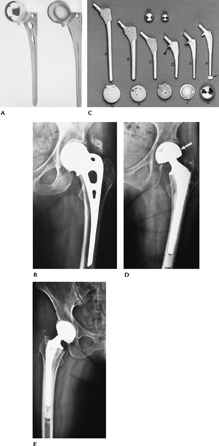
FIGURE 16-29 Hip arthroplasty components. (A) Unipolar Moore prosthesis (courtesy of Zimmer, Warsaw, IN). (B) Radiograph of the Moore prosthesis. (C) Photographs of hip systems with (arrowhead) and without collars. (A) Porous-coated anatomic (PCA) with long stem; (B) PCA with medium stem; (C) PCA with short stem; (D) Precision stem with medial collar (arrowhead); (E,F) Precision stems with distal centralizer in F (arrow). Top: 32- and 26-mm heads. Bottom: Acetabular components seen from the attachment side (G–J) and (D) radiograph of a bipolar component. Note the cup (arrow) encloses the head of the femoral component. (From
Berquist TH, ed. Imaging atlas of orthopedic appliances and prostheses. New York: Raven Press; 1995.
) (E) Radiograph of a total hip arthroplasty with cemented femoral and uncemented acetabular components. |
P.1017
P.1018
 |
|
FIGURE 16-30 Normal postoperative features. (A)
AP radiograph showing zones for the acetabular (I–III) and femoral (1–7) components used to evaluate lucent lines and cement technique. There are no lucent lines at the bone–cement interface (arrowheads) of the femoral component or metal–bone interface of the acetabular component. (B) The acetabular component should be angled 45 degrees (35–55 degrees accepted) to the ischial tuberosity line. This line measures leg length changes as it intersects the lesser trochanter. Note the irregular lucency (arrow) indicating a loose right acetabular component. (C) Lateral radiograph demonstrating the angle formed by the acetabular component to a vertical line is 15 degrees (normal–neutral to 15 degrees). |
P.1019
P.1020
 |
|
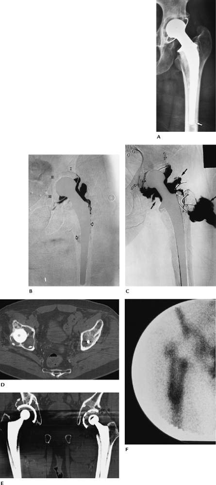
FIGURE 16-31 Hip arthroplasty complications. (A) Radiograph showing a lucent line around the tip of the femoral component (arrow). (B) Subtraction arthrogram showing contrast around the femoral stem (open arrows) and in all three zones of the acetabular component caused by loosening. (C) Infection and loosening. Subtraction arthrogram showing contrast in zones I and III about the acetabular component (open curved arrows) and around the upper femoral component caused by loosening. There is an irregular pseudocapsule and communicating abscess (solid arrows). (D,E) Axial (D) and coronal (E) CT images demonstrate advanced osteolysis about the acetabular components bilaterally. (F)
Radionuclide scan 2 years after surgery (scans can be positive for up to 1 year) demonstrating intense increased tracer around the femoral component caused by loosening and infection. |
P.1021
Suggested Reading
Berquist TH. Imaging atlas of orthopedic appliances and prostheses. New York: Raven Press; 1995:266–351.
Berry
DJ, Harmsen WS, Cabanela ME, et al. Twenty-five year survivorship of
two thousand consecutive primary Charnley total hip replacements.
Factors affecting survivorship of acetabular and femoral components. J Bone Joint Surg 2002;84A:171–177.
DJ, Harmsen WS, Cabanela ME, et al. Twenty-five year survivorship of
two thousand consecutive primary Charnley total hip replacements.
Factors affecting survivorship of acetabular and femoral components. J Bone Joint Surg 2002;84A:171–177.
P.1022
Knee Arthroplasty
Key Facts
-
Knee arthroplasty was developed as an
alternative to arthrodesis. The goals are to relieve pain and improve
motion, stability, and function. -
Indications: osteoarthritis, traumatic arthritis, rheumatoid arthritis
-
Contraindications: arthrodesis,
infection. Patients with excessive physical demands or obesity are not
good candidates for knee arthroplasty. Other patient factors include
age, gender, and systemic disorders. Ten-year survival of knee implants
is 93% in females and 88% in males. Ten-year survival for patients aged
less than 55 years at the time of surgery is 83% compared with 94% for
patients aged more than 70 years at the time of surgery. -
Preoperative evaluation includes a clinical scoring system for pain level, motion, functionality, and stability.
-
Imaging evaluation:
Radiographs Full-length standing AP,
lateral, and patellar views. Measure mechanical axis, anatomic axis,
and femorotibial angle on standing AP.CT Bone stock MRI Soft tissue support or avascular necrosis -
Component and procedure selection:
depends on bone stock, soft tissue support, patient compliance, and
surgical preference. The least constrained prosthesis is used for
primary joint replacement.Unicompartmental: Isolated medial or lateral compartment arthrosis Bicompartmental: Tibiofemoral surface replacement Tricompartmental: Tibiofemoral and patellar resurfacing. Most frequently used approach. -
Components are polyethylene with or without metal backing and may be designed to be used with or without cement.
-
Postoperative imaging/complications:
-
Normal component position:
AP radiograph Tibial tray 90 degrees to tibial axis (±15 degrees). >90 degrees = valgus position; <90 degrees = varus position.
Femoral angle 97 to 98 degrees
Femorotibial angle 5 to 7 degrees valgusLateral radiograph Tibial tray 90 degrees to tibial axis. >90 degrees = extended; <90 degrees = flexed.
Femoral component to femoral axis neutralPatellar view Symmetric position without patellar tilt -
Complications of knee arthroplasty are summarized in Table 16-7.
-
P.1023
|
TABLE 16-7 KNEE ARTHROPLASTY COMPLICATIONS
|
|||||||||||||||||||||||||||||||||
|---|---|---|---|---|---|---|---|---|---|---|---|---|---|---|---|---|---|---|---|---|---|---|---|---|---|---|---|---|---|---|---|---|---|
|
|||||||||||||||||||||||||||||||||
P.1024
 |
|
FIGURE 16-32 Knee components. (A) Femoral components for revision (1), cruciate sparing (2), and posterior stabilized with standard (3) and porous coating (4). (B) Tibial component (1) with polyethylene spacer (arrowhead) and augmentation stem for revision (arrow). Conventional tibial component with metal tray (2) and all-polyethylene tibial component (3). (C) All-polyethylene (1) and metal-backed (2) patellar components.
|
P.1025
 |
|
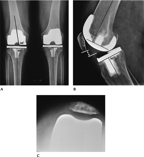
FIGURE 16-33
Normal postoperative appearance and component position. Fluoroscopic positioning is preferred to evaluate component interfaces. (A) Standing AP of the knees. Tibial tray should be 90 degrees to the tibial axis (R = 88 degrees, L = 90 degrees). Angles <90 degrees = varus; >90 degrees = valgus. Femoral component should be at 98 degrees to the femoral shaft. (B) On the lateral radiograph, the tibial tray should be 90 degrees to the tibial axis. <90 degrees = flexion; >90 degrees = extension. The femoral component should be perpendicular to the femoral axis. The patella should be 9 to 10 mm above the polyethylene margin (lines, arrows). (C) Normally positioned patella on the sunrise view. |
P.1026
 |
|
FIGURE 16-34 Complications. Patellar (A) and lateral (B) radiographs of displaced patellar components. (C) Notch view demonstrating a fractured tibial tray (arrow).
|
P.1027
 |
|
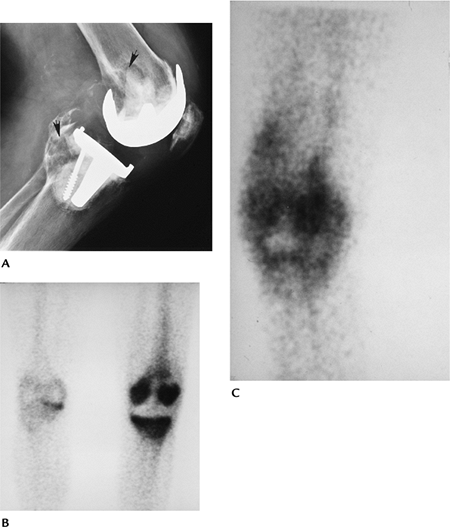
FIGURE 16-35 Infection and loosening. (A) Lateral radiograph demonstrating osteolysis in the posterior femur and tibia (arrows). Technetium-99m methylene-diphosphonate (B) and indium-111–labeled leukocyte scans (C) showing increased tracer in the knee caused by infection and loosening.
|
Suggested Reading
Berquist TH. Imaging atlas of orthopedic appliances and prostheses. New York: Raven Press; 1995:437–539.
Kurtz
S, Mowat F, Ong K, et al. Prevalence of primary revision of total hip
and knee arthroplasty in the United States from 1990 through 2002. J Bone Joint Surg 2005;87A:1487–1497.
S, Mowat F, Ong K, et al. Prevalence of primary revision of total hip
and knee arthroplasty in the United States from 1990 through 2002. J Bone Joint Surg 2005;87A:1487–1497.
Rand JA, Trousdale RT, Ilstrup DM, et al. Factors affecting the durability of primary total knee prostheses. J Bone Joint Surg 2003;85A:259–265.
P.1028
Ankle Arthroplasty
Key Facts
-
Ankle arthroplasty was devised to relieve
pain and improve function. In recent years, new designs have improved
the feasibility of good results. -
Indications: traumatic arthritis, osteoarthritis, rheumatoid arthritis
-
Contraindications: arthrodesis, avascular necrosis of the talus
-
Preoperative evaluation includes pain
level, stability, and function. Radiographs may be adequate for
preoperative evaluation. CT is useful for bone stock, and MRI is useful
for soft tissue support and avascular necrosis. -
Component and procedure selection: Ankle
implants usually are polyethylene with metal backing, but ceramic
implants also are available. Three major implants are primarily used
today: Scandinavian Total Ankle Replacement (STAR), Buechel-Pappas, and
the Agility total ankle prosthesis. All are placed without cement. -
Postoperative imaging/complications: Serial radiographs are useful for identifying most complications. Table 16-8 summarizes complications and imaging approaches.
|
TABLE 16-8 ANKLE ARTHROPLASTY COMPLICATIONS
|
|||||||||||||||||||||||||||
|---|---|---|---|---|---|---|---|---|---|---|---|---|---|---|---|---|---|---|---|---|---|---|---|---|---|---|---|
|
|||||||||||||||||||||||||||
P.1029
 |
|
FIGURE 16-36 STAR ankle replacement. AP (A) and lateral (B) radiographs of an uncemented STAR total ankle replacement.
|
P.1030
 |
|
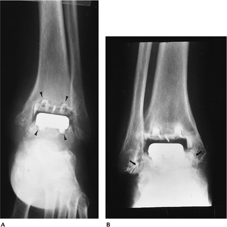
FIGURE 16-37 Complications. (A) AP radiograph demonstrating lucent lines (arrowheads) about both components caused by loosening. (B) AP radiograph demonstrating impingement medially and laterally (arrows).
|
Suggested Reading
Anderson T, Montgomery F, Carlsson A. Uncemented STAR total ankle prostheses. J Bone Joint Surg 2003;85A:1321–1329.
Spirt AA, Assal M, Hansen ST. Complications and failure after total ankle arthroplasty. J Bone Joint Surg 2004;86A:1172–1179.
P.1031
Metatarsophalangeal Arthroplasty
Key Facts
-
Arthroplasty of the metatarsophalangeal
(MTP) joints was developed as an alternative to cheilectomy,
arthrodesis, or resection arthroplasty. -
Indications: hallux valgus, hallux rigidus, osteoarthritis, rheumatoid arthritis, failed surgical procedures
-
Contraindications: infection, paralysis, arthrodesis
-
Preoperative evaluation includes
assessment of pain level and function. Imaging should include standing
AP and lateral radiographs to evaluate foot angles. CT may be useful to
access bone loss. -
Component and procedure selection varies
with patient activity and surgical preference. Components may be
metal-polyethylene or single- or double-stemmed silicone implants. -
Postoperative imaging/complications:
Clinical improvement and image features are important to assess success
of MTP arthroplasty. Table 16-9 summarizes complications and imaging approaches.
|
TABLE 16-9 METATARSOPHALANGEAL ARTHROPLASTY COMPLICATIONS
|
||||||||||||||||||
|---|---|---|---|---|---|---|---|---|---|---|---|---|---|---|---|---|---|---|
|
||||||||||||||||||
P.1032
 |
|
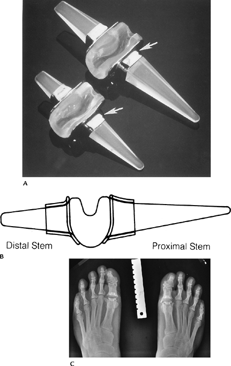
FIGURE 16-38 MTP implants. (A) Swanson Silastic double-stemmed implants with grommets (arrows) to prevent wear. (B) Lateral illustration. (Courtesy of Wright Medical Technology, Arlington, TN.) (C) Standing radiograph of bilateral great toe Silastic implants. Note marginal osteophyte formation.
|
P.1033
 |
|
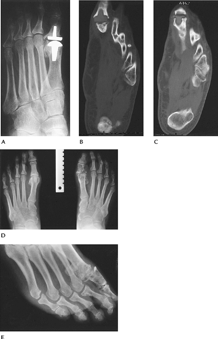
FIGURE 16-39 Complications. (A) Great toe metal implant system with lucent lines around the components caused by loosening. (B,C) CT images of a loose, fractured (arrowhead) Silastic great toe implant. Standing AP (D) and oblique (E) radiographs showing fragmentation of the Silastic implant with osteolysis resulting from particle disease.
|
P.1034
Suggested Reading
Cracchiolo A III, Weltmer JB, Lian G, et al. Arthroplasty of the first metatarsophalangeal joints. J Bone Joint Surg 1992;71A:552–563.