
adults and adolescents. Because of its subcutaneous location and
because it is frequently the site of direct injury, tibial fractures
are open more often than other long bone fractures. Even in closed
fractures, severe soft-tissue injury may be evident or initially
suspected. Swelling, fracture blisters, and even subsequent
full-thickness skin loss may complicate an initially closed fracture.
Compartment syndrome may be present in open as well as closed
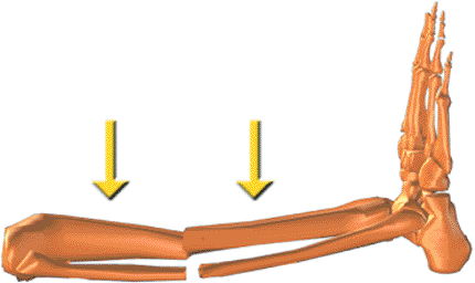
fractures. In addition to injuries caused by direct trauma, the tibia
and fibula may fracture as a result of torsional and bending forces.
This usually occurs at the junction of the distal 1/4 tibia where there
is the lowest section modulus.
open fractures with bone loss, (b) fractures with compartment syndrome,
(c) open fractures, (d) unstable closed fractures, and (e) fractures
with subsequent loss of reduction following initial casting. Although
not addressed specifically in this chapter, delayed union, nonunion,
and malunion of the tibia can also be treated with the Spatial Frame.
for the worst clinical situations, there is no contraindication for its
use as the primary definitive method for acute shaft fractures.
the limb and complete neurovascular assessment, which must be repeated
regularly to detect impending compartment syndrome. In the conscious
patient, increasing pain and decreasing sensation are the earliest
signs and symptoms of compartment syndrome. The limb must be inspected
for open wounds and hemarthrosis of the knee or ankle. The entire lower
extremity is then splinted in a well-padded, long, leg splint to
achieve at least gross realignment of the fragments.
Proximal
or distal shaft fractures may include extension into the joint. If the
initial anteroposterior (AP) and lateral radiographs of the tibia and
fibula from knee to ankle are suspicious but inconclusive for
intra-articular extension, a computed tomography (CT) scan including
the joint should be obtained to help aid diagnosis and treatment.
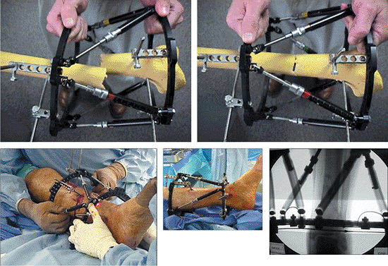
reduction or gradual reduction. In the simplest mode, after fracture
fragments are fixed, the frame can be acutely manipulated to reduce the
fracture under direct vision for open fractures and c-arm control for
closed and open fractures. The frame is then locked in position. No
computer is necessary for this type of acute reduction. In the most
versatile mode, any frame may be gradually adjusted to reduce the
fracture. This reduction is done daily and gradually usually over 1 to
2 weeks. Additional anesthetics are unnecessary. This gradual reduction
can be used for the entire reduction process or after an initial acute
reduction.
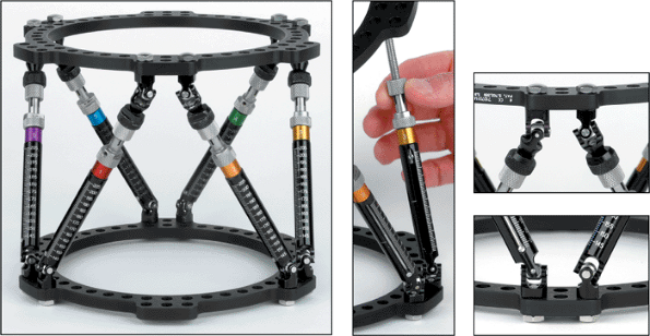
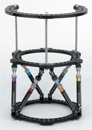
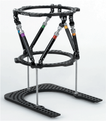
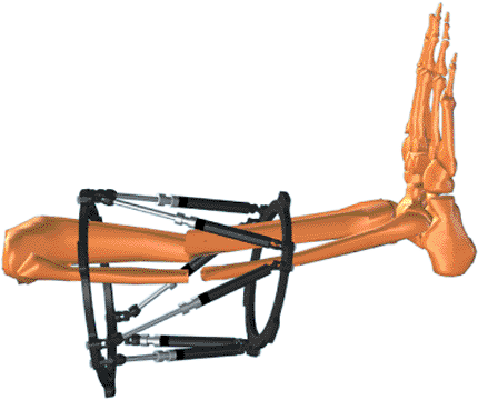
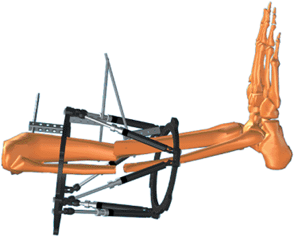
or partial rings connected by six telescopic struts with special
universal joints (Fig. 30.1). By adjusting only
strut lengths, one ring can be repositioned with respect to the other.
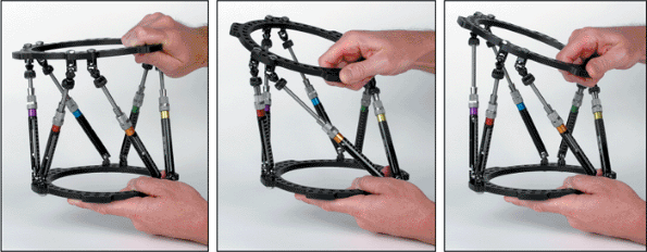
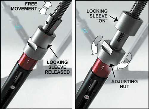
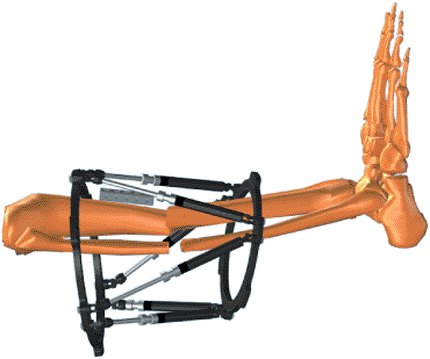
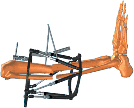
Special FastFx struts have two modes of adjustment. In the unlocked
position, they are free to slide like a piston for an initial reduction
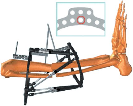
in surgery (Fig. 30.2). In the locked mode, the
struts can be gradually adjusted allowing further reduction of the
residual skeletal deformity in the clinic or patient’s home (Fig. 30.3).
The Spatial Frame fixator is capable of correcting all six axes of the
deformity, three translations, two angulations, and rotation by
adjusting lengths of struts only.
after the surgical application allows the surgeon to divorce fracture
fixation from reduction. The surgeon can concentrate on a stable fix of
major fragments during surgery with relative disregard of reduction.
After stable fixation, the fragments can be acutely reduced with the
FastFx struts in their unlocked
position
or gradually reduced in the locked position. This ability to achieve
delayed near anatomic reductions is the greatest strength of the
Spatial Frame technique.
 |
|
Figure 30.1.
One Spatial Frame ring can be repositioned with respect to the other by adjusting strut lengths. (Copyright © J. Charles Taylor.) |
 |
|
Figure 30.2. A Spatial Frame may be acutely adjusted by hand with all struts in the unlocked position. (Copyright © J. Charles Taylor.)
|
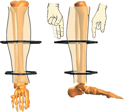
to make them less cumbersome and safer while descending stairs.
Generally 1 to 2 fingerbreadths clearance anterior between the ring and
skin and 2 to 3 fingerbreadths posteriorly are adequate (Fig. 30.4).
To allow full knee flexion, a 2/3 ring with open posterior is
frequently used for proximal tibial fractures. Complete and 2/3 rings
range in size from 80- to 300-mm internal diameter and are available in
25-mm increments. Accessory rings and partial rings may be attached to
extend the levels of fixation (Fig. 30.5).
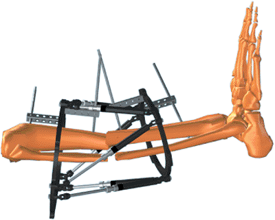
Standard and short foot plates are available in 155- and 180-mm
internal diameters. U plates are also used for foot fixation (Fig. 30.6).
 |
|
Figure 30.3.
Fast Fx struts are free to slide in the unlocked position for acute fracture reduction. The locking sleeve is advanced to lock the strut. The locked strut can still be gradually adjusted by rotation of the nosepiece. (Copyright © J. Charles Taylor.) |
 |
|
Figure 30.4.
Spatial Frames may be tapered and eccentric. Sufficient soft-tissue clearance should be allowed to prevent frame impingement. (Copyright © J. Charles Taylor.) |
 |
|
Figure 30.5.
A tapered frame consisting of a 180-mm diameter 2/3 ring proximally connected to a 155-mm Spatial Frame, distally, Ilizarov threaded rods. The proximal 2/3 ring with the opening positioned posteriorly allows full knee flexion. (Copyright © J. Charles Taylor.) |
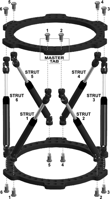
The open area of a 2/3 ring can be positioned based on surgeon’s
choice. Six identifier clips, uniquely colored and numbered 1 through
6, are provided with each frame. Each numbered/colored clip is applied
to a strut beginning with strut 1 (which is attached to a tab directly
anterior on the proximal ring) and progressing counterclockwise as
viewed from the proximal end of the frame.
 |
|
Figure 30.6.
Additional skeletal stability and prevention of equinus deformity may be gained by fixing the foot to a foot plate or U plate. (Copyright © J. Charles Taylor.) |
 |
|
Figure 30.7.
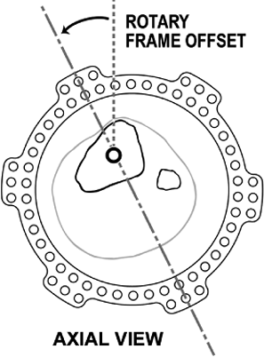
Each numbered and colored clip is applied to a strut beginning with strut no. 1 (which is attached anteriorly to the designated master tab) and progressing counterclockwise as viewed from the proximal end of the frame. The computer program assumes the universal joints connecting strut no. 1 and no. 2 to the proximal ring are aligned directly anterior with respect to the reference fragment. Different rotational alignments, especially for more proximal femoral and humeral applications, can be accommodated by changing rotary frame offset. (Copyright © J. Charles Taylor.) |
diameter stainless-steel wires were designed to be used with the
Spatial Frame. To minimize the number of pins and wires, their
placement should be optimized to provide the greatest stability within
anatomic constraints. The entire length of the anterior/medial tibia is
available for half pin fixation. Four millimeter and 5-mm titanium half
pins are used for adolescents and small adults. Usually 6-mm half pins
are used in large children and adults.
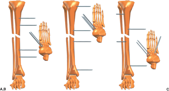
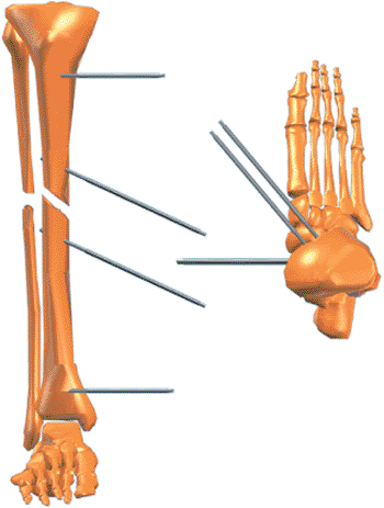
three half pins in different planes. Pins should be spread
longitudinally along a significant portion of each fragment but out of
the zone of soft-tissue injury (Fig. 30.8). Obviously this is not always possible.
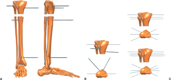
two multiplanar half pins at approximately 70 degrees to each other.
Adding a single olive wire in the coronal plane adds significant
stability to a short fragment.
The crossing angle of these wires must be optimized within anatomic
limits. Olives should block the fragment from each side and the third
olive wire should be blocking the fracture obliquity. Stability for a
very short proximal tibial fragment
can be increased by transfixing the tibia and fibula at the level of the fibular head with a tension wire.
 |
|
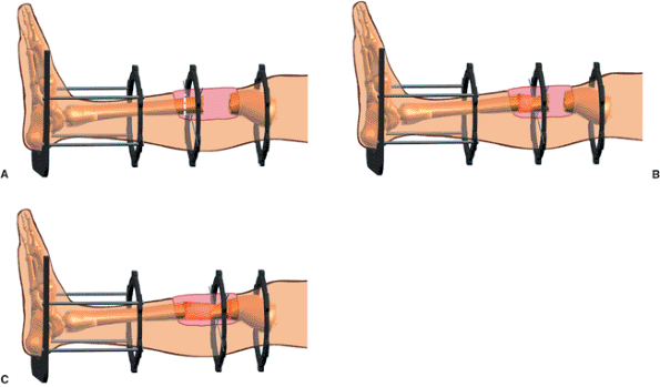
Figure 30.8. A. The surgeon should not limit mechanical stability by two sets of parallel pins. B. Fracture stability is significantly improved by extending the working length in each fragment. C.
Stability is further increased by inserting pins in different planes, achieving multiplanar fixation. (Copyright © J. Charles Taylor.) |
 |
|
Figure 30.9. A. Short peri-articular fragments can be stabilized with two or three multiplanar half pins. B. Stability is improved significantly by at least one tension wire. C.
For short extra-articular fragments, good stability is provided by three multiplanar tension wires. Four multiplanar wires are used for intra-articular fractures such as a bicondylar tibial-plateau fracture. (Copyright © J. Charles Taylor.) |
 |
|
Figure 30.10. The accessory foot plate or U plate is attached to the Spatial Frame with threaded rods. (Copyright © J. Charles Taylor.)
|
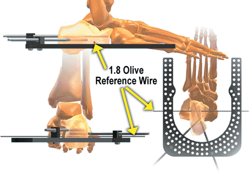
wires can be used as needed in the syndesmotic region. Intermediate
length fragments may be fixed with a combination of wires and half pins.
fracture stability, soft tissue immobilization, and prevention of
equinus contracture. A distal shaft fracture with significant
soft-tissue injury and especially with peripheral nerve injury or
closed head injury should have the fixation extended to the foot at
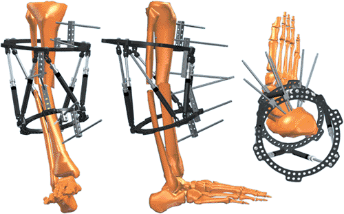
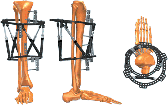
least temporarily (Fig. 30.10). The foot plate
is attached to the distal ring of the Spatial Frame with threaded rods.
Usually a combination of olive wires and half pins are placed in the
calcaneus and two wires are placed in the metatarsals (Fig. 30.11). Shorter frames may be constructed with short body struts. Tapered
and open-section frames may be applied. Segmental fractures are usually
treated with a ring or 2/3 ring for each major fragment (Fig. 30.12).
 |
|
Figure 30.11.
Angled wires and/or pins are used in the calcaneus. Usually two wires are used in the forefoot (not shown) at the level of the metatarsal necks. (Copyright © J. Charles Taylor.) |
 |
|
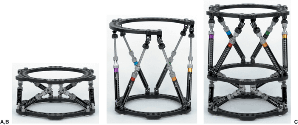
Figure 30.12. A. Shorter struts allow more stable fixation when indicated. Accessory rings could be added to extend level of fixation. B. The component system permits custom frames such as this tapered open-section frame for distal femoral application. C.
Each ring has six tabs and can serve as the intermediate ring for a segmental application. Spatial Frames come preassembled or can be assembled from components. (Copyright © J. Charles Taylor.) |
steerage pins on either side of the fracture (1). These pins should be
angled 15 to 20 degrees from the transverse plane along the plane of
the fracture (Fig. 30.13). These pins will cause dynamic interfragmentary compression
with weight bearing and minimize fracture shear. It is still beneficial if only one steerage pin is used.
 |
|
Figure 30.13.
Steerage pins are angled 15 to 20 degrees, approximating the major oblique-fracture plane. They are placed on each side of the fracture and are used with other pins and/or wires. Steerage pins increase interfragmentary compression and reduce shear at the fracture site during ambulation. (Copyright © J. Charles Taylor.) |
be used as indicated. The patient is positioned supine on a padded
radiolucent table top. The most user-friendly tables contain no metal
rails (even peripherally) to interfere with visualization with the
image intensifier. The image intensifier should be positioned on the
opposite side of the injury. A well-padded tourniquet is placed about
the proximal thigh but generally is only used during debridement of
open fractures. Even if used for debridement, the tourniquet should be
deflated prior to pin and wire insertion. Longitudinal traction through
a calcaneal wire may be used to improve overall alignment, but it is
rarely used. A few folded towels are used to elevate the leg segments
as needed as the frame is applied.
of the most important factors for patient tolerance, frame longevity,
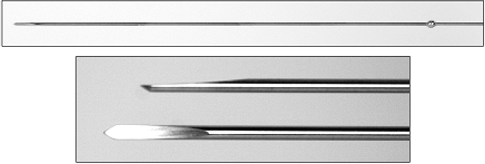
and minimization of need for additional surgery. Bayonet point wires
with cutting relief are the safest for metaphyseal and especially
diaphyseal bone (Fig. 30.14). Wires are
inserted percutaneously to the near cortex, then slowly drilled across
both cortices with frequent pauses to prevent overheating, and tapped
through the far soft tissue. The wire is bathed in saline for
additional cooling. The surgeon should strive to achieve bicortical
purchase with wires and pins to enhance mechanical purchase and
decrease thermal necrosis. If burned bone is in the flutes of the
predrill for half pins or on the tip of the emerging bayonet tipped
wire, do not use that pin or wire. The small incision to insert the
drill sleeve or release the skin for the olive is closed with a simple
suture.
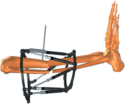
After choosing the approximate level for one ring, the surgeon marks
the skin. Then the surgeon marks the skin 18 cm away for the position
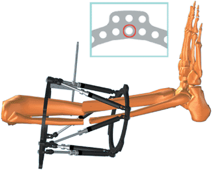
of the second ring (Fig. 30.15). The surgeon then slides the frame onto the leg (Fig. 30.16). The frame need not be centered longitudinally over the fracture. Make a short longitudinal incision
for a sagittal-plane half pin. Using a five-hole Rancho Cube as a drill guide (Fig. 30.17), the surgeon drills a pilot hole for the half pin. After inserting the half pin (Fig. 30.18), the surgeon attaches it to an appropriate length Rancho Cube while maintaining the desired soft-tissue clearance (Fig. 30.19). The Rancho Cube is attached to the Spatial Ring via the inner tier of holes at the anterior position (Fig. 30.20)
on the master tab, the junction of the no. 1 and no. 2 struts. Using as
long a Rancho Cube as possible, the surgeon inserts a half pin in the
anterior-medial plane off the proximal face of the proximal ring (Fig. 30.21). Using a Rancho Cube as a drill guide (Fig. 30.22), the surgeon inserts a half pin in the sagittal plane on the proximal portion of the distal fragment (Fig. 30.23).
Maintaining 1 to 2 fingerbreadths of soft-tissue clearance, the surgeon
then attaches the Rancho Cube to the pin in the distal fragment (Fig. 30.24). The Rancho Cube is attached to the distal ring in the anterior hole (Fig. 30.25).
 |
|
Figure 30.14. Olive wire with close-up of cutting tip. (Copyright © J. Charles Taylor.)
|
 |
|
Figure 30.15.
Determine the approximate position of one ring, usually on the shorter fragment, and mark the skin. Place a second mark 18 cm from the first for FastFx struts or 15 cm for standard struts. These marks are the approximate positions for the rings. (Copyright © J. Charles Taylor.) |
 |
|
Figure 30.16. The frame is slid over the leg. (Copyright © J. Charles Taylor.)
|
 |
|
Figure 30.17. Lay a long Rancho Cube along the tibial crest for a sagittal pin. (Copyright © J. Charles Taylor.)
|
 |
|
Figure 30.18.
Using the Rancho Cube as a drill sleeve guide, the surgeon drills the appropriate pilot hole and inserts a half pin by hand. (Copyright © J. Charles Taylor.) |
 |
|
Figure 30.19.
The Rancho Cube is slid along the pin to adjust anterior/posterior soft-tissue clearance, and the pin is tightened to the cube with a set screw or short bolt. (Copyright © J. Charles Taylor.) |
 |
|
Figure 30.20.
The Rancho Cube is attached to the anterior hole of the ring via the inner tier of holes. See inset. (Copyright © J. Charles Taylor.) |
 |
|
Figure 30.21.
With as long a Rancho Cube as possible, a second half pin is inserted in the anterior medial plane. (Copyright © J. Charles Taylor.) |
 |
|
Figure 30.22. A long Rancho Cube is laid along the tibial crest of the second fragment for a sagittal pin. (Copyright © J. Charles Taylor.)
|
 |
|
Figure 30.23.
Using the Rancho Cube as a drill sleeve guide, the surgeon drills the appropriate pilot hole and inserts a half pin by hand. (Copyright © J. Charles Taylor.) |
 |
|
Figure 30.24.
The Rancho Cube is slid along the pin to adjust anterior/posterior soft-tissue clearance, and the pin is tightened to the Rancho Cube with a set screw or short bolt. (Copyright © J. Charles Taylor.) |
 |
|
Figure 30.25.
The Rancho Cube is attached to the anterior hole of the ring via the inner tier of holes. See inset. (Copyright © J. Charles Taylor.) |
 |
|
Figure 30.26.
With as long a Rancho Cube as possible, a second half pin is inserted in the anterior medial plane. (Copyright © J. Charles Taylor.) |
the anterior-medial plane through use of as long a half pin as possible
(Fig. 30.26). Usually a third half pin is
inserted in each fragment in a different plane and attached to their
respective rings with a one- or two-hole Rancho Cube (Fig. 30.27).
Stability can be increased on longer fragments by extending the spread
of fixation with an accessory ring connected to one of the primary
rings with threaded rods or posts (see Fig. 30.5).
each pin or wire entry is covered by a piece of Xeroform or Adaptic
dressing and a gauze sponge. The leg is wrapped with a roll gauze
dressing. The foot, if not included in the frame, is supported in
plantigrade position with a sling or postoperative shoe tied to the
Spatial Frame.
 |
|
Figure 30.27.
Usually a third half pin is inserted in each fragment in an intermediate plane. This third pin is usually attached to the ring with a one- or two-hole Rancho Cube. (Copyright © J. Charles Taylor.) |
 |
|
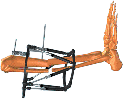
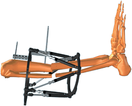
Figure 30.28. With struts unlocked, the frame is manipulated to reduce the fracture. Struts are then locked. (Copyright © J. Charles Taylor.)
|
 |
|
Figure 30.29.
After pin and wire fixation of each major fragment, with all struts unlocked, the fracture is reduced under c-arm control or direct vision for open fractures. Each strut is then locked, thereby securing the reduction. (Copyright © J. Charles Taylor.) |
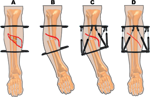
soft-tissue defect sometimes present in open fractures. After initial
stabilization, rather than trying to achieve anatomic reduction, the
surgeon can position fragments with a certain amount of shortening and
angulation, allowing the muscle and skin to be apposed. This
malreduction can be held for weeks if necessary, allowing the soft
tissues to heal without tension. The fragments can then be gradually
reduced obviating the need for more complex plastic coverage (Fig. 30.30).
indication for external fixation, remote osteotomy, and bone transport
into the defect. The Spatial Frame allows the transported fragment to
be positioned accurately on the docking site without reoperation (Fig. 30.31).
deformity, recording the proximal and distal ring diameters and the six
strut lengths, and measuring the position of the frame on the limb, the
surgeon can gradually reduce fractures utilizing the total residual
deformity correction method.
 |
|
Figure 30.30. A. Open fractures may have a soft-tissue defect if anatomically reduced. B.
With overriding and angulation, the soft tissue gap might be eliminated or at least significantly reduced. The vascular status must be closely monitored. C. Struts are applied in the malreduced position and the soft tissues are allowed to heal over 2 to 4 weeks. D. The fracture is gradually reduced. (Copyright © J. Charles Taylor.) |
 |
|
Figure 30.31.
The Spatial Frame can be used for bone transport. Usually the Spatial struts are used at the docking site. Regular threaded rods or Spatial struts can be used for the osteotomy site. The foot may be included for additional soft-tissue and boney stability. Antegrade or retrograde transport may be performed. (Copyright © J. Charles Taylor.) |
measuring six deformity parameters: the three projected angles
(rotations) and three projected translations between major fragments.
The frame parameters consist of proximal and distal ring diameters and
the strut lengths. Four mounting parameters are measured
radiographically and clinically after surgery for acute fractures: AP
view, lateral view, axial, and rotary frame offsets.
determines new strut lengths for the Spatial Frame fixator, which will
completely correct the skeletal deformity. “Structure at risk” and a
“safe velocity” options may be selected to control precisely a gradual
reduction.
distal fragment with respect to the proximal fragment. The proximal
fragment is the reference fragment; the distal fragment is the moving
or deformed fragment.
fragment is characterized with respect to a reference distal fragment.
This characterization of the deformity by describing abnormal position
of the proximal fragment is especially useful in distal fractures with
a short distal fragment. The location of the attachment of the distal
ring (using the joint surface as a landmark) will be more exactly
determined in surgery and postoperative measurement than the level of
attachment of the proximal ring on the longer proximal fragment. It
also allows the surgeon to fully characterize the deformity even though
the radiographs are too short to include the level of attachment of the
proximal ring. The distal fragment is the reference fragment; the
proximal fragment is the moving fragment.
-
The reference fragment should be one with anatomic planes that most closely match the planes of the AP and lateral radiographs.
-
AP and lateral radiographs include the level of attachment of a ring to the reference fragment.
femoral or proximal tibial fractures. The foot provides a prominent
landmark for distal tibial fractures. Frequently, the best choice for
the reference fragment is the short fragment in conjunction with the
prominent landmark. The x-ray technician is more likely to align
successfully with the landmark (criterion 1) and if the joint line is
included in the radiographs (as it should), then the level of
attachment of a ring to that fragment is also included (criterion 2).
characterizes the distal fragment with respect to the proximal fragment
or alternatively characterizes the proximal fragment with respect to
the distal fragment. However, the working measurements of even an
oblique, plane, angular deformity will be different depending upon
which fragment is chosen as the reference fragment. The final external
fixation frames for these different deformity characterizations (based
on alternative reference fragments) are identical and will effect the
same complete correction. It is important that the same fragment be
maintained as reference fragment for AP and lateral radiographs as well
as the clinical exam for malrotation.
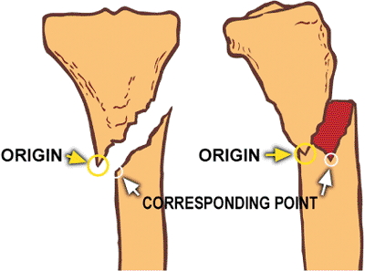
on the reference fragment to its corresponding point on the moving
fragment. The best choices for origin and corresponding point are
points that are coincident in the anatomic (reduced) state. The tip of
a spike on the reference fragment and the matching notch on the moving
fragment would be reasonable choices in posttraumatic deformity if
these points are easily discerned on AP and lateral radiographs. (Fig. 30.32).
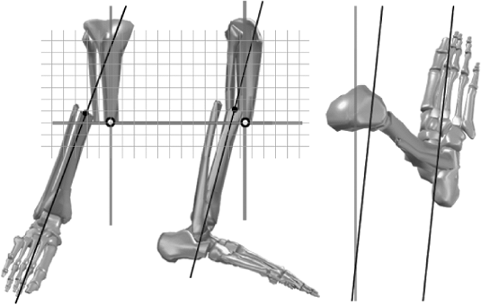
reference fragment and the mechanical axis at the fracture site on the
moving fragment are the most commonly used choices for origin and
corresponding Point (Fig. 30.33). The implied
coordinate system on which these translational and rotational
measurements are made is the coordinate system of the reference
fragment. The AP view translation, lateral view translation, and axial
translation are measured along grid lines that can be envisioned to
align with the mechanical axes of the reference fragment.
 |
|
Figure 30.32.
A spike and its matching notch, if discernible on AP and lateral films, is one possible choice for the origin and corresponding point, which are used to measure translations at the fracture site. (Copyright © J. Charles Taylor.) |
 |
|
Figure 30.33.
Measurements of translation and rotation are made along an imaginary grid aligned to the reference fragment. (Copyright © J. Charles Taylor.) |
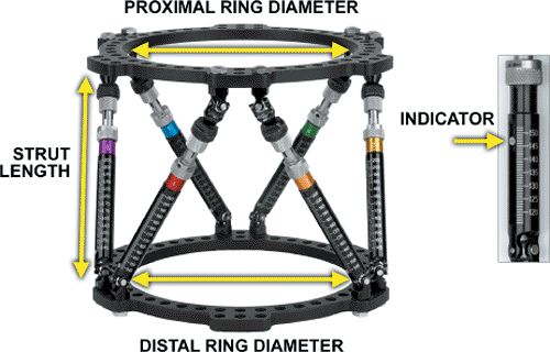
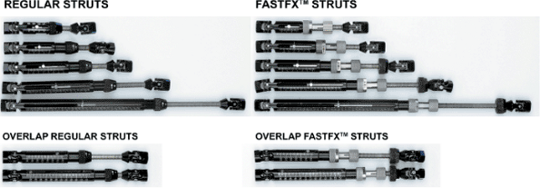
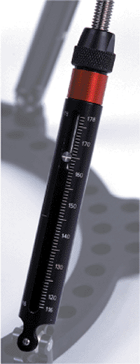
medium, and long sizes ranging in functional length from 75 to 284 mm.
For any size, the strut has a specific range from its shortest to
longest length and a midposition marked on each strut. Struts are
marked with millimeter graduations with the actual strut length printed
every 10 mm. The achievable strut length overlaps by a few millimeters
at each transition from one body to the next (Fig. 30.35). The strut length is read at the indicator (Fig. 30.36).
 |
|
Figure 30.34.
The frame parameters, the description of the frame, consist of the internal diameters of the ring that are printed on the rings and the strut lengths that are read at the indicator of each strut. (Copyright © J. Charles Taylor.) |
 |
|
Figure 30.35.
Struts are available in xx-short, x-short, short, medium, and long bodies. The achievable length of struts overlap by 5 to 10 mm from one body to the next in the series. (Copyright © J. Charles Taylor.) |
the two fragments are angulated and translated. The translations are
measured as the separation of the adjacent (or corresponding) point
from the origin. Translations are measured along the coordinate axes of
the reference fragment (actually the reference ring).
Translation is measured between the origin and its corresponding point
on AP and lateral views. Axial translation can be measured on either
radiograph as the distance between the interior ends of fragments
measured along the reference fragment centerline. AP and lateral
angulations are measured as the angles between respective centerlines;
the axial angle is measured clinically.
 |
|
Figure 30.36. Strut length is read directly at the indicator pin. (Copyright © J. Charles Taylor.)
|
 |
|
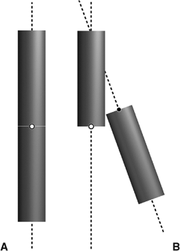
Figure 30.37. A.
When anatomically reduced, the origin and corresponding point are coincident and there is no angulation or rotation between the fragments. B. In general, there could be a six axes deformity, consisting of three translations and three angulations, after initial fracture reduction. (Copyright © J. Charles Taylor.) |
 |
|
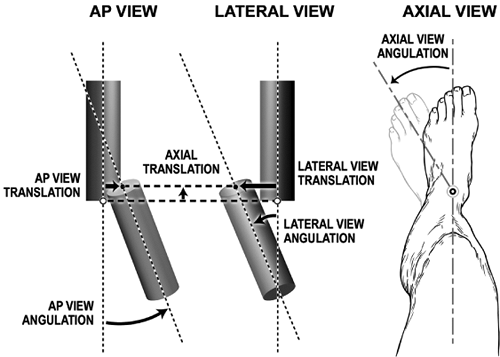
Figure 30.38.
Translation (displacement) is the perpendicular distance from the reference fragment to its corresponding point on the moving fragment. To measure translations, the surgeon determines where the corresponding point is with respect to the origin. (If a distal reference is chosen, the AP view and lateral view translations will generally be opposite those of proximal reference.) Note that angulation and rotation are determined based on a view of the deformity from the reference fragment. For example, if a proximal reference is chosen and the AP view along the reference fragment shows a varus deformity, then it is a varus deformity. If a distal reference is chosen and an axial view taken along the axis of the distal fragment (usually in a clinical exam) shows that the distal fragment is internally rotated with respect to the proximal fragment, then it is an internal rotation deformity. (Copyright © J. Charles Taylor.) |
position of the reference ring with respect to the origin: axial frame
offset, AP-view frame offset, lateral-view frame offset, which are
measured on postoperative films, and rotary frame offset. The latter is
generally assessed by clinical inspection.
This can generally be measured on AP or lateral films. This measurement
in millimeters partially specifies the orientation of the frame with
respect to the origin.
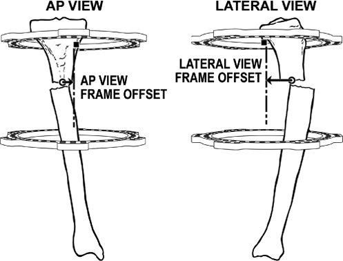
AP view, the distance from the origin to the centerline of the rings
should be measured. This distance is the AP-view frame offset. (Figs. 30.40A and 30.41).
In most tibial mountings with circular fixators, the tibia is located
anterior to the geometric center of the ring. The distance from the
origin to the centerline of the frame should be measured. This distance
in millimeters is the lateral-view frame offset (see Figs. 30.40B and 30.41).
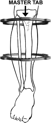
Taylor Spatial Frame is with the proximal-ring universal joints (master
universal joints) for Strut 1 and Strut 2 located exactly anterior on
the proximal fragment (Fig. 30.42). When used
for fractures, the frame may be inadvertently malrotated when applied.
To correct the malrotation, the surgeon enters the angular position of
the sagittal plane of the reference ring with respect to the reference
fragment in rotary frame offset (see Figs. 30.7 and 30.43).
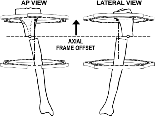 |
|
Figure 30.39.
The mounting parameter, axial frame offset, is used to measure the axial distance from the origin to the reference ring. (Copyright © J. Charles Taylor.) |
structures at risk on the concavity of the deformity. When dealing with
rotation about the longitudinal axis in addition to conventional
angular correction, the risks may be fewer or greater depending on
direction of axial rotation. For example, when correcting a
flexion-valgus external-rotation deformity of the proximal tibia, the
peroneal nerve is at increased risk. However, when correcting a
flexion-valgus internal-rotation deformity, the axial rotation will
tend to offset the stretch on the peroneal nerve created during the
correction of the flexion valgus.
 |
|
Figure 30.40. A.
AP-view frame offset, one of the four mounting parameters, is measured from the origin to the centerline of the frame on AP view. B. Lateral-view frame offset, measured from a lateral view, describes the distance from the origin to the centerline of the frame. (Copyright © J. Charles Taylor.) |
 |
|
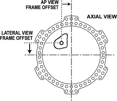
Figure 30.41.
The AP- and lateral-view frame offsets describe how the center of the reference ring is positioned in a transverse plane with respect to the origin. (Copyright © J. Charles Taylor.) |
coordinates of the structure at risk with respect to the origin and set
the maximum daily displacement of the structure at risk. The program
creates a daily adjustment schedule moving the structure at risk the
prescribed amount each day until the deformity is eliminated (fracture
is reduced).
 |
|
Figure 30.42.
The Spatial Frame computer program assumes the master tab is always directly anterior on the proximal ring. (Copyright © J. Charles Taylor.) |
 |
|
Figure 30.43.
Rotary frame offset, one of the four mounting parameters, is measured clinically as rotation of the sagittal plane of the reference ring with respect to the sagittal plane of the reference fragment. (Copyright © J. Charles Taylor.) |
measuring radiographs, or excessive preload and bending of wires and
pins, there may still be residual skeletal deformity when the struts
have reached their target lengths at the completion of a total residual
deformity correction. By measuring the radiographs to determine new
deformity parameters and making a clinical exam for malrotation, the
surgeon can determine new strut lengths to correct the residual
deformity through the Total Residual Deformity Correction Program. New
mounting parameters can be entered if the original parameters were in
error. Alternatively, during any gradual correction a total
residual-deformity correction may be undertaken by measuring current
parameters and noting current strut settings.
Program, prepares an adjustment schedule to correct any residual
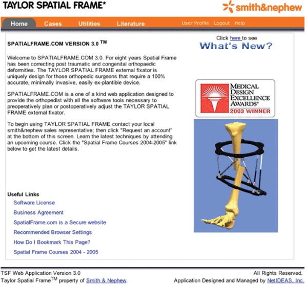
skeletal deformity after a Spatial Frame is applied (Fig. 30.44).
The surgeon can progress from tab to tab in the program only if
sufficient information has been submitted at each step. The program
will prompt the surgeon for all necessary information.
notes, can be saved to a secure, international, Internet server. Saved
cases can be reopened and modified, then saved again as a different
case or scenario.
 |
|
Figure 30.44. Home Section
for Web-based software used to prepare gradual schedule for deformity correction, including residual skeletal deformity after fracture application. (Copyright © J. Charles Taylor.) |
 |
|
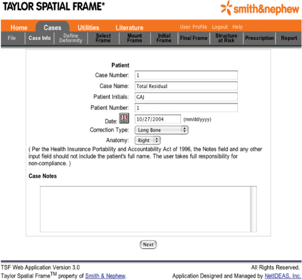
Figure 30.45. Cases Section, Case Info must include at least “Long Bone” as the Correction Type and “Right” or “Left” as Anatomy. (Copyright © J. Charles Taylor.)
|
side (“Left” or “Right”). For tibial fractures, he/she selects “Long
Bone” as the Correction Type (Fig. 30.45). Case Name will appear as the default title of the case when the case is finally saved.
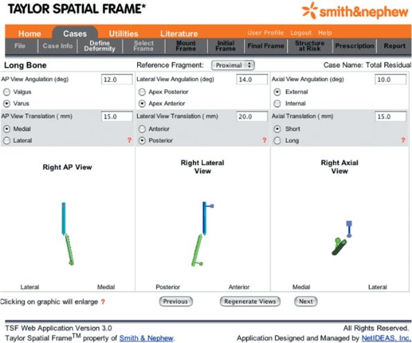
is then selected, the software provides the surgeon with updated AP,
lateral, and axial views of the skeletal deformity. The pointed end of
the blue rod is the origin and the pointed end of the green rod is the
corresponding point. Using the pull-down menu in the next window, the
surgeon selects the “Proximal Ring Diameter,” “Distal Ring Diameter,”
and “Strut Body Type” (Fig. 30.47).
surgeon and patient information is reiterated. The mounting parameters,
initial and final strut settings, the coordinates of the structure at
risk, as well as the safe velocity are shown in table form. The daily
adjustment schedule is also
provided.
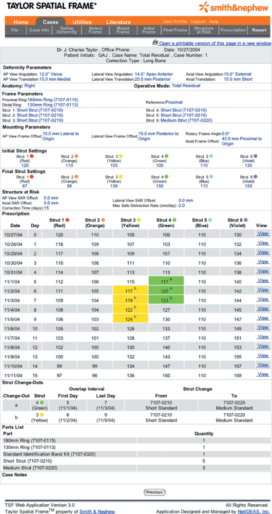
Critical days when struts need to be exchanged are highlighted, color
coded, and identified with a letter. The strut exchanges are listed and
explained in chronological order, and a list of necessary Spatial Frame
parts is also given.
 |
|
Figure 30.46. Define Deformity provides for the selection of the Reference Fragment
and input of the deformity parameters. After deformity parameters are input, a schematic representation of the deformity appears after the “Regenerate Views” button is selected. (Copyright © J. Charles Taylor.) |
 |
|
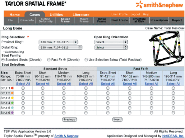
Figure 30.47. Select Frame
identifies the diameter of the rings used as well as the location of the open section of the ring for 2/3 rings and foot plates. Also, the type of strut and body size are input for each of the six struts. (Copyright © J. Charles Taylor.) |
 |
|
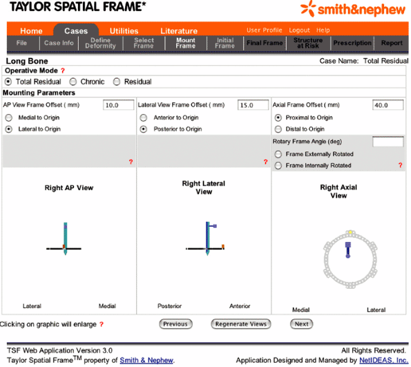
Figure 30.48. Mount Frame
is used to select the operative mode being utilized, which is almost always the “Total Residual” for fractures. Also, the mounting parameters are input in this section. (Copyright © J. Charles Taylor.) |
 |
|
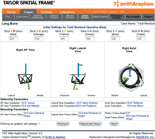
Figure 30.49. Initial Frame
for fractures is used to input each of the six strut lengths after the acute fracture reduction. (Copyright © J. Charles Taylor.) |
 |
|
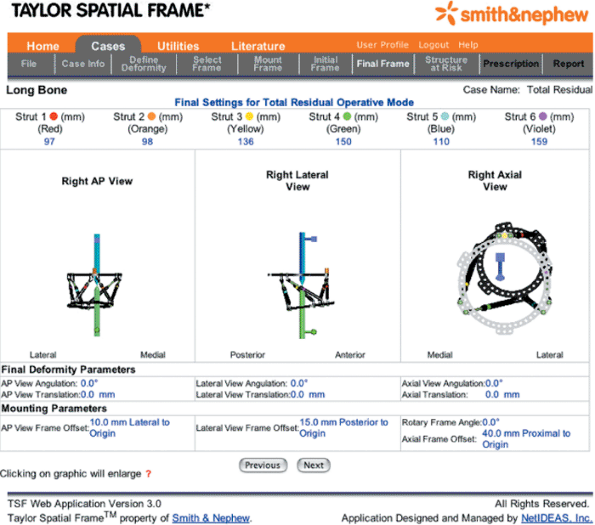
Figure 30.50. Final Frame
is an output area for the six new strut lengths that will correct the residual skeletal deformity. Also, a graphic of the corrected frame appears. (Copyright © J. Charles Taylor.) |
 |
|
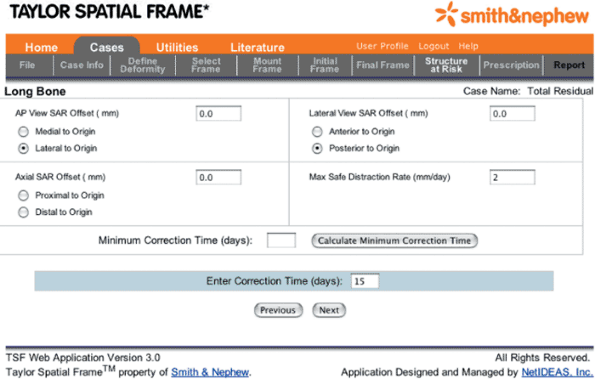
Figure 30.51. Structure at Risk
is used to input the location of the structure on the concavity of the deformity that is to be protected by controlling the rate of correction. Also, the Max Safe Distraction Rate can be selected. Alternatively the Correction Time may be arbitrarily set. (Copyright © J. Charles Taylor.) |
 |
|
Figure 30.52. Report reiterates all surgeon inputs, and it outputs a frame adjustment Prescription, a Strut Change-out Schedule, and a Parts List. (Copyright © J. Charles Taylor.)
|
 |
|
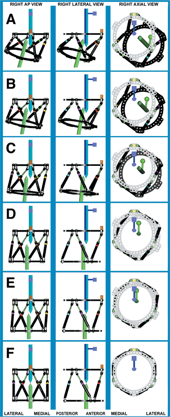
Figure 30.53. A–D. A Waypoint Reduction, though rarely needed, may be performed by inputting the deformity parameters in two separate steps. A first Total Residual Correction
is run with “AP View Angulation,” “Lateral View Angulation,” “Rotation,” and “Length” as the deformity parameters to get the fragments to the way point position. D–F. Next, a second Total Residual Correction is run with “AP View Translation” and “Lateral View Translation” as the deformity parameters to get the fragments to anatomic position. (Copyright © J. Charles Taylor.) |
prepare a daily schedule to reduce a fracture that is significantly
overlapped by using a Waypoint. In the case shown in Figure 30.53 angulation, rotation, and length are corrected in the first step (see Fig. 30.53 rows A, B, C, and D), and translation is corrected in a second step (see Fig. 30.53
rows D, E, and F). In the first step, only the deformity parameters
pertaining to angulation, rotation, and length are input to achieve the
corresponding strut lengths to get to the Waypoint.
Next, to take the fragments from the waypoint to anatomic position, AP-
and lateral-view translation are entered as the only deformity
parameters.
when their general condition allows. Cleaning of the pin-skin interface
is usually commenced 5 to 7 days postoperatively, often in the
outpatient clinic. If good AP and lateral radiographs were not obtained
in the hospital, they are taken at this first postoperative visit.
These initial radiographs need to be wide enough to include the full
diameter of the ring so that mounting parameters can be accurately
measured. The patient is seen at 1 to 2 week intervals, especially
while the frame is being gradually adjusted. Adjustments are usually
performed over 1 to 2 weeks for fracture reductions. As many
adjustments as necessary can be performed. Usually one or two
adjustment schedules are run for fractures.
Fracture healing time averages 18 weeks and ranges from 7 to 24 weeks
depending on a number of factors. Wires that suddenly become painful
may have lost tension and should be retensioned in the office.
bearing on the injured leg. Patients usually will go to a single crutch
by 8 to 10 weeks and fully weight bearing by 12 weeks. When the patient
is fully weight bearing and if radiographs show that the fracture
appears healed, one or two struts are removed in the office and the
patient walks around the office for 30 minutes. If the patient
experiences no pain, he or she walks at home for a week with only four
struts in place. If subsequent radiographs show no change in position
of the fragments, the fracture still appears healed, and the patient
reports no increase in pain, the frame is removed. Most frames are
removed in the office with local anesthetic. More complex frames are
removed in surgery under general anesthetic or IV sedation. A
prefabricated short-leg walking brace is used for a few weeks in most
cases.
mechanically stable frame with pins and wires cautiously inserted. The
surgeon should be vigilant and perform Total residual deformity
corrections of any skeletal deformity remaining after initial operative
reduction. Precautions should be taken to prevent equinus contracture,
including, sometimes, foot fixation. Patients should strive for to be
fully weight bearing.
postoperatively to assess the arterial supply to the foot. An acute
arterial injury in surgery might be picked up by an absent pulse or
continued bleeding from a pin or wire site. Late bleeding from a pin or
wire is usually from arterial erosion and often requires emergent
surgical treatment.
aggressively. If the patient is able to actively extend the ankle above
neutral, a padded night splint or sling may be used to prevent equinus
contracture. If the patient is unable to actively dorsiflex the ankle
to neutral because of swelling or pain, then the foot should be placed
in a sling or post operative shoe with straps to the Spatial Frame.
Alternatively, a Dynasplint may be used to prevent
progression
of the equinus and to bring the foot to neutral slowly as swelling and
pain subside postoperatively. As stated earlier, patients with
fractures that are distal, open, with associated peroneal nerve injury,
or those found in conjunction with closed head injury or compartment
syndrome are at greater risk for developing a contracture and probably
should have the foot included in the frame even though fracture
stability is satisfactory with only the tibial fragments fixed.
Frequent periods of at least partial weight bearing are beneficial to
fracture healing and the prevention of contracture.
healing, especially if multiple transfixion wires were used, will
resolve with weight bearing and physical therapy. Persistent
contracture can be treated with application of a spanning Spatial Frame
across the ankle, gradual correction of the equinus, and 4 to 5 mm of
distraction across the ankle.
with the Spatial Frame still on the tibial shaft fracture by applying a
foot plate and connecting it to the most distal tibial ring with
Ilizarov hinges placed along the ankle axis, or if space permits,
applying Spatial Frame struts between the distal tibial plate and the
foot plate and performing a deformity correction.
antibacterial soap and water beginning at approximately day 5 if
soft-tissue wounds allow. A light-pressure gauze sleeve about wires
emerging through muscles will decrease soft-tissue motion along the
pin. Antibiotics by mouth are frequently but not always needed in the
4.5 months average healing time of adult fractures treated with
external fixation. A wire that suddenly becomes painful is usually
loose and can be retensioned in the office, usually with immediate
relief of pain. Pins or wires that develop redness or drainage are
treated by initiating PO antibiotics, increasing dose, or (rarely) IV
antibiotics. Pin or wire sites that do not respond should be treated
with pin removal, curettage if sequestrum is suspected, and additional
pin insertion if the removed pin was mechanically essential.
fixation from healing that looks like primary bone to that with a more
fusiform appearance. In several series the average time to healing for
adult tibial fractures treated with primary external fixation is
approximately 4.5 months. Varus/valgus or flexion/extension stress
views with the struts removed, or a CT scan can be performed to assess
healing. If fragments are well reduced and there are no signs of
healing at 3 months, an autogenous bone graft should be considered.
Also, the mechanical stability of the construct should be questioned.
The frame may need to be revised by adding pins, wires, or even an
accessory ring to extend the level of fixation.
closely analyzed to determine a best course for subsequent treatment.
Treatment options include cast or brace, repeat external fixation,
intramedullary nail, or plate fixation with or without autogenous bone
grafting.
results with other external fixation, intramedullary nails, and plating
of tibial fractures. During its development, the Spatial system was
thoroughly tested for theoretical accuracy of the computer program,
combined mechanical accuracy in correcting severe six-axis deformities,
and frame stiffness. The computer program is mathematically accurate to
within 1/106 of an inch and a 1/104 of a degree.
The combined mechanical accuracy of the program, as applied to the
frame by hand, is 1 mm translation and 0.6-degree angulation. The
Spatial Frame is as stiff as the Ilizarov in axial loading and twice as
stiff in bending and torsion.
1996. Although initially reported for fractures and deformity
correction (2), its early acceptance was for deformity correction and
nonunions (3–8) and has gradually gained acceptance for primary
treatment of fractures (5,9–14). Historically, malunion was the leading
complication of external fixation, which reflects the difficulty in
making adjustments to other frames after the initial surgery and the
reluctance to return to surgery. Not only does repeat surgery pose a
risk to the patient, but an effort to improve one aspect of fracture
reduction another could result in a complication for another aspect of
it.
the Spatial Frame in the postoperative period is the greatest strength
of the system. The program provides a daily adjustment schedule for the
struts, which are easy to adjust using the direct read indicator for
each strut. McFadyen and Atkins (10) demonstrated a 100% compliance of
their patients adjusting the frame as prescribed. Near anatomic
realignment and repositioning of the externally fixed, major fragments
has been routinely achieved. Binski and Hutchinson (9), McFadyen and
Atkins (10) as well as Whately (14) report a 95 to 100% rate of
anatomic or near anatomic restoration of alignment and position.
Likewise, these same authors report a 96 to 100% rate of primary union
and remarkably low rates of reoperation (approximately 5%) for delayed
union.
JC. Dynamic interfragmentary compression in oblique fractures
stabilized with half pin external fixation: the steerage pin. Poster
presented at: Annual Meeting of the American Academy of Orthopaedic
Surgeons. New Orleans, LA; February 1994.
JC. Complete characterization of a 6-axes deformity; complete
correction with a new external fixator, “The Spatial Frame.” Presented
at: The Annual Meeting of Association for the Study and Application of
the Method of Ilizarov; North America 1997.
SR, Helfet DL, Blyakher A. Distraction of hypertrophic nonunion of
tibia with deformity using Ilizarov/ Taylor Spatial Frame. Arch Orthop Trauma Surg 2002;122:295–298.
JC. The Taylor Spatial Frame. Presented at: The Annual Meeting of
Association for the Study and Application of the Method of Ilizarov;
New Orleans, LA; 1998.
JC. The Rings First Method for Fractures and Deformity Correction.
Presented at: The Annual Meeting of Association for the Study and
Application of the Method of Ilizarov; North America; 1999.
JC. The Spatial Frame as a reconstructive hinge: theoretical and
practical considerations. Presented at the Annual Meeting of
Association for the Study and Application of the Method of Ilizarov;
North America; 2000.
JC. 6, 6 + 6, and 6 × 6 correction of ankle and foot deformities with
the spatial frame. Presented at: The Annual Meeting of Association for
the Study and Application of the Method of Ilizarov; North America;
2003.
JC. Reconciliation of CORA and Origin/Corresponding Point Methods of
Deformity Characterization. Presented at: The Annual Meeting of
Association for the Study and Application of the Method of Ilizarov;
North America; 2004; Toronto, Ontario, Canada.
JA, Hutchinson B. Treatment of tibial shaft fractures with the Taylor
Spatial Frame. Paper presented at: The International Society for
Fracture Repair; Novermber 2–6, 2004; Bologna, Italy.
I, Atkins R. The Taylor Spatial Frame in limb reconstruction; review of
100 cases. Presented at: The British Orthopaedic Association Annual
Congress. September 15–17, 2004; Manchester, England.
JC. The last malunion with primary external fixation of fractures: the
power of residual deformity correction with the Spatial Frame.
Presented at: The Annual Meeting of Association for the Study and
Application of the Method of Ilizarov North America; 2000.
JC. Skew parameters and the total residual deformity correction: a
geometric method. Presented at: The Annual Meeting of Association for
the Study and Application of the Method of Ilizarov; North America;
2001.
JC. Complete correction of residual deformity following chronic
deformity correction or fracture external fixation: the total residual
deformity correction. Presented at: The Annual Meeting of Association
for the Study and Application of the Method of Ilizarov; North America;
2002.
C. The Taylor Spatial Frame for acute tibial fractures. Presented at:
the Annual Meeting of As sociation for the Study and Application of the
Method of Ilizarov; North America; 2004; Toronto, Ontario, Canada.