
patient to his/her prefracture level of function. There is general
agreement that in the patient who sustains an intertrochanteric hip
fracture, this can best be accomplished through surgery. Nonoperative
management is appropriate only in nonambulators, often with multiple
medical co-morbidities, who experience minimal discomfort from the
injury. Occasionally, younger healthy patients who have a completely
nondisplaced intertrochanteric fracture can be managed nonoperatively;
however, these patients must be closely followed to detect evidence of
fracture displacement. All patients treated nonoperatively should be
rapidly mobilized to avoid the complications of prolonged recumbency,
such as decubitus, deep venous thrombosis (DVT), aspiration, and the
like.
for intertrochanteric fractures; however, the most important aspect of
any classification is the determination of fracture stability.
Stability is provided by the presence of an intact posteromedial
cortical buttress. Unstable fracture patterns include those with loss
of the posteromedial buttress, fractures with subtrochanteric
extension, and reverse obliquity fractures.
plate for stable intertrochanteric hip fractures and an intramedullary
nail for unstable fracture patterns, particularly in younger
individuals. Following fixation of intertrochanteric fractures with a
stable fracture pattern, there should be minimal fracture settling,
limb shortening, or medialization of the distal fragment. I prefer a
variable angle hip screw (VHS) (EBI, Parsippany, NJ) because it allows
some adjustment of the fracture alignment once the screw and plate
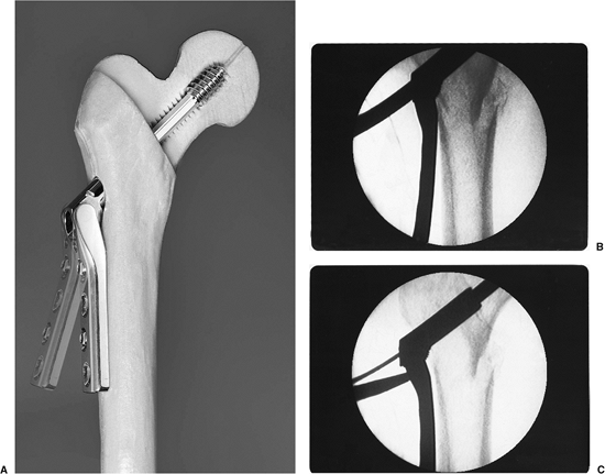
assembly has been implanted (Fig. 16.1). The
use of this implant also helps with inventory control as a single plate
can allow a range of plate angles, from 89 to 159 degrees. For unstable
fracture patterns, I prefer use of an intramedullary hip screw (IMHS)
device because it prevents excessive fracture collapse and deformity.
The lag screw portion of the intramedullary devices can telescope
within the nail only until the femoral head and neck segment abuts the
intramedullary nail.
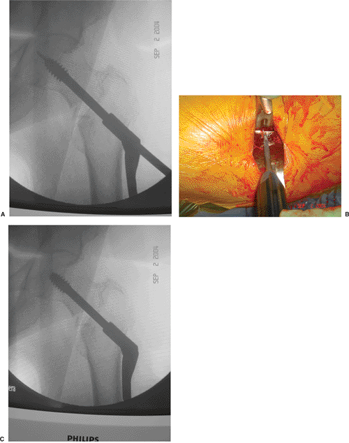
 |
|
Figure 16.1. A. Photograph of the VHS system demonstrating the adjustability of the plate angle. B. Radiographs after initial plate placement and (C) after use of the mechanism to bring the plate to the lateral femoral cortex.
|
extremity varies depending on fracture displacement and comminution.
Nondisplaced fractures may present with virtually no clinical
deformity, while displaced fractures present with the classic shortened
and externally rotated extremity. Range of motion of the hip can be
painful and should be avoided. Neurovascular injuries are rare, but a
careful evaluation should be performed. Hip fractures following
high-energy trauma require a careful work-up to rule out the
possibility of associated injuries.
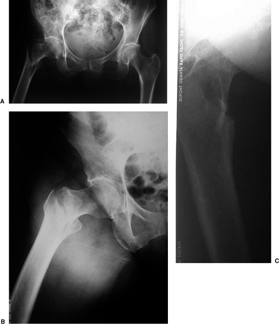
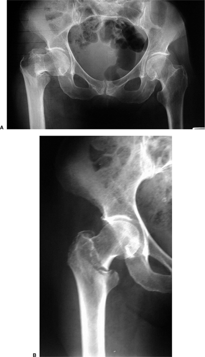
suspected hip fractures include an anteroposterior (AP) view of the
pelvis, and an AP and cross-table lateral of the injured proximal femur
(Fig. 16.2). A cross-table lateral radiograph
is necessary to evaluate the posteromedial cortex for signs of
comminution. In situations where the fracture geometry is not clear due
to deformity, an AP view of the hip internally rotated 15 to 20 degrees
may be helpful (Fig. 16.3). An AP view of the
contralateral side is helpful, particularly as a means of assessing the
size and angle of the implant for intramedullary fixation.
 |
|
Figure 16.2. A. AP view of the pelvis. B. An AP and (C) cross-table lateral view of the hip revealing a right intertrochanteric fracture.
|
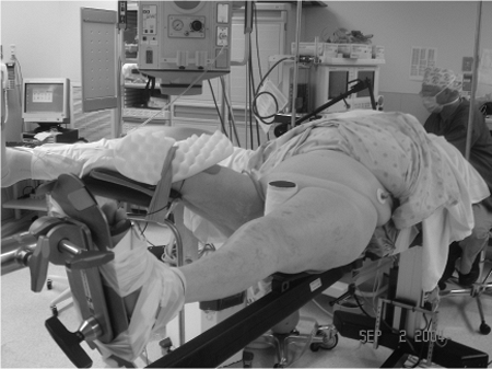
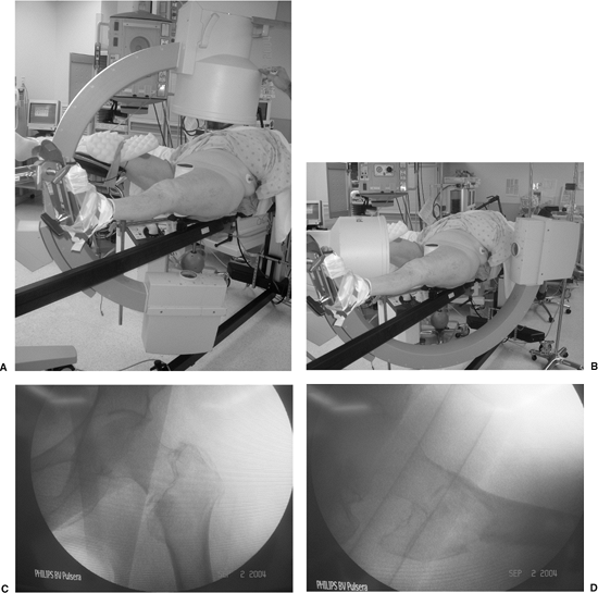
patient is positioned supine on a fracture table, with care taken to
pad and protect the labia or scrotum against the peroneal post. Once
the patient is properly positioned, a mobile c-arm intensifier is
positioned to allow visualization of the hip in AP and lateral planes.
Most intertrochanteric hip fractures can be reduced using gentle
longitudinal traction with the leg externally rotated followed by
varying degrees of internal rotation. The uninvolved leg must be
positioned so that it does not block positioning of the image
intensifier for a lateral view (Fig. 16.4).
before prepping the patient and be certain that nonobstructive,
biplanar, radiographic visualization of the entire proximal femur,
including the hip joint, is obtainable (Fig. 16.5). Inadequate visualization of the entire proximal femur can result in technical errors, such as inappropriate lag screw
positioning or length. Varus angulation often results in guide pin
positioning in the inferior femoral neck and superior femoral head. The
surgeon must be prepared to deal with residual varus angulation,
posterior sag, or malrotation. Varus angulation can usually be
corrected by placing additional traction on the lower extremity to
disengage the fracture fragments. Occasionally, one may need to abduct
the lower extremity to correct a varus malreduction. If residual varus
remains, one should check the position of the fracture fragments on the
lateral radiographic view, as posterior sag may prevent adequate
fracture reduction. In this situation, traction should be released and
the fracture manipulated to disengage the fragments. Attempting
fracture fixation with varus angulation or posterior sag can lead to
difficulty centering the lag screw in the femoral head.
 |
|
Figure 16.3. Use of internal rotation with gentle traction to evaluate a right, proximal, femur fracture.
|
 |
|
Figure 16.4.
Patient positioning for stabilization of a left intertrochanteric fracture with the uninvolved leg flexed, abducted, and externally rotated. |
 |
|
Figure 16.5. Positioning of the image intensifier for (A) AP and (B) lateral radiographic views. C. AP and and (D) lateral radiographs of a reduced intertrochanteric fracture prior to patient draping.
|
 |
|
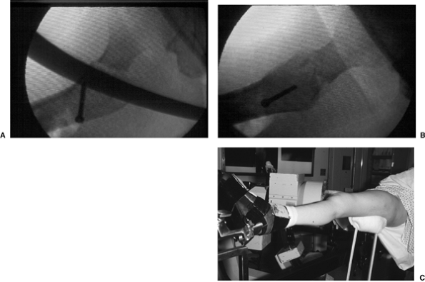
Figure 16.6. A. Posterior sag after intertrochanteric fracture reduction can be corrected with use of a (B,C) crutch placed under the proximal thigh.
|
If unrecognized, posterior sag can result in guide pin positioning in
the anterior femoral neck and posterior femoral head. After a
satisfactory reduction has been achieved, I rotate the lower extremity
under fluoroscopy to determine whether the fracture fragments move as a
single unit. In those patients where the femoral shaft moves
independently of the proximal fragment, excessive internal rotation of
the leg should be suspected. In these cases, the lower extremity should
be placed in neutral or slightly external rotation. Once the fracture
is fully reduced, the patient is prepped and draped.
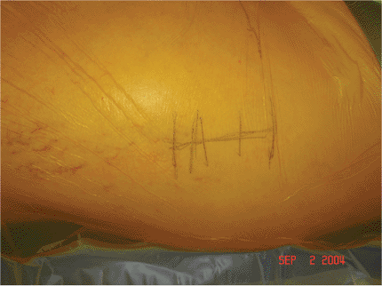
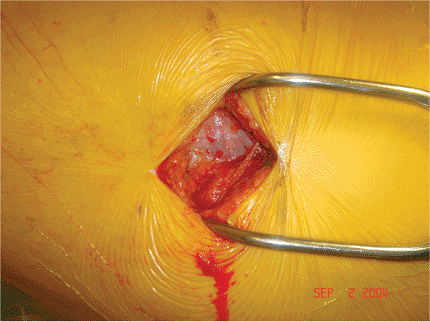
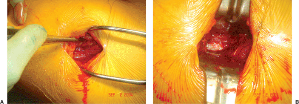
to the greater trochanter and extending distally in line with the
femoral shaft (Fig. 16.7). The length of the
incision depends upon the patient’s size. The iliotibial band is
exposed and incised in line with its fibers (Fig. 16.8). The vastus lateralis is elevated from the intermuscular septum and the lateral aspect
of the proximal femur dissected of soft tissue (Fig. 16.9).
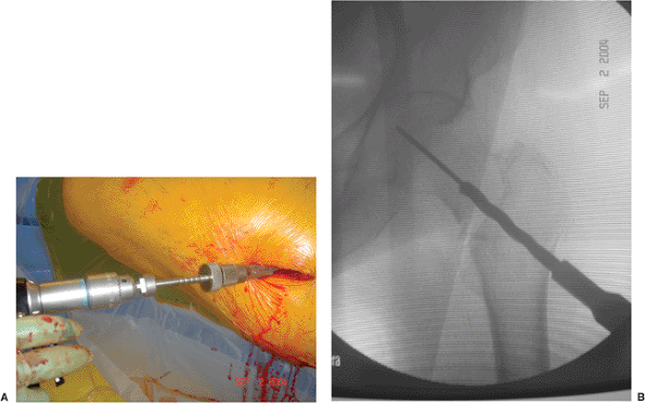
Using image intensification, a guide pin is inserted into the femoral
neck and head using an angle guide. Most commercially available
sliding-hip screws are available in plate angles of from 125 to 155
degrees, of which the 135- and 150-degree devices are the most popular.
I usually select a 135-degree device because its use facilitates lag
screw placement into the desired central portion of the femoral head,
and because of its entry point in metaphyseal cancellous bone, it
decreases the stress riser effect of a higher-angle device.
 |
|
Figure 16.7.
A straight 3- to 4-cm lateral incision is initiated just distal to the greater trochanter and is extended distally in line with the femoral shaft. |
 |
|
Figure 16.8. Exposure of the iliotibial band.
|
insertion into the femoral neck and head using either an angle guide or
freehand technique with later adjustment of the plate to accommodate
the selected angle. I prefer to use the angle guide because it helps
ensure placement of the guide pin at the desired 135 degree angle and
to a check to proper fracture reduction; inability to place the guide
pin into the center of the femoral head and neck using this angle
should alert the surgeon to the possibility of a fracture malreduction.
in the center of the femoral head and neck on both the AP and lateral
planes within 5 to 10 mm of the subchondral bone (Fig. 16.10).
Central and deep placement allows lag screw purchase in the best bone
available as well as allows maximal collapse of the screw before its
threads engage the plate barrel.
 |
|
Figure 16.9. A.
After incising the iliotibial band, the surgeon exposes the vastus lateralis and then elevates it from the lateral aspect of the proximal femur. B. Homan retractors are placed under the vastus lateralis, exposing the lateral femoral shaft. |
 |
|
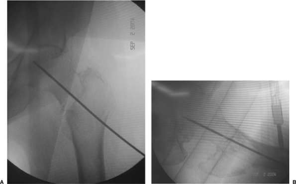
Figure 16.10. A. AP and (B) lateral image-intensifier radiographs of the inserted guide pin.
|
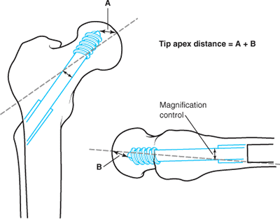
distance (TAD) to determine the ideal position of the lag screw within
the femoral head. This measurement, expressed in millimeters, is the
sum of the distances from the tip of the lag screw to the apex of the
femoral head on both the AP and lateral radiographic views (after
controlling for radiographic magnification) (Fig. 16.11).
Peripheral malposition of the lag screw is not differentiated from
shallow lag screw positioning; only the actual distance from the tip of
the lag screw to the apex of the femoral head is considered.
 |
|
Figure 16.11.
The TAD, expressed in millimeters, is the sum of the distances from the tip of the lag screw to the apex of the femoral head on both the AP and lateral radiographic views. |
Baumgaertner et al in a series of 198 intertrochanteric fractures
treated with a compression hip screw. In their series, 16 (8%)
fractures had loss of fixation secondary to lag screw cutout of the
femoral head. However, no lag screw cutout occurred when the TAD was 27
mm or less, regardless of patient age, fracture stability, quality of
fracture reduction, or type or angle of implant used. Conversely, lag
screw cutout rate increased to 60% when the TAD was greater than 45 mm.
Using multivariate, logistic, regression analyses, Baumgaertner et al
demonstrated that screw position as measured by the TAD was the
strongest (though not the only) independent predictor of lag screw
cutout. (Unstable fractures and increasing patient age were also
predictive of lag screw cutout.) They therefore recommended that if
guide pin location yields a TAD of more than 25 mm, the surgeon should
reassess the fracture reduction and/or reposition the guide pin.
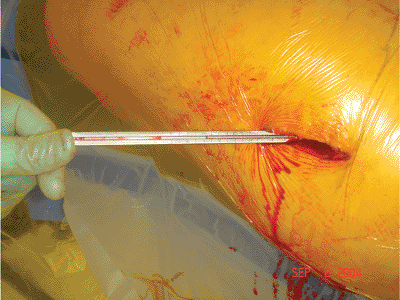
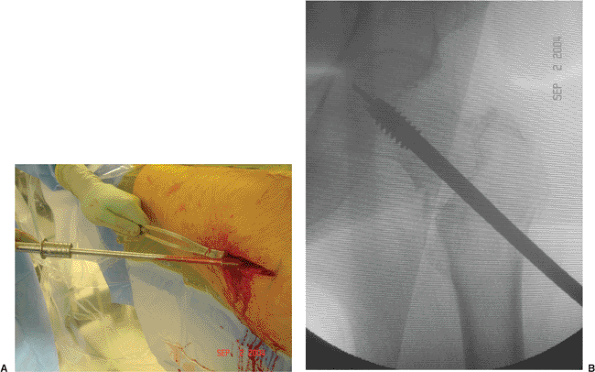
position, it is advanced to the level of the subchondral bone and the
length of the lag screw is measured (Fig. 16.12).
Reaming of the femoral neck and head over the guide pin is performed
under image intensification to the desired final position of the lag
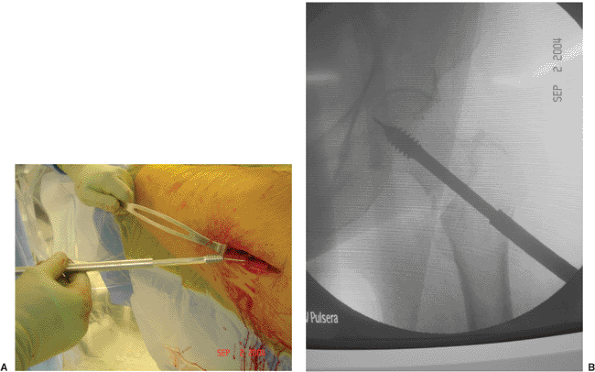
screw (Fig. 16.13). I recommend that the reamed
tract be tapped, even in the elderly, to prevent femoral head rotation
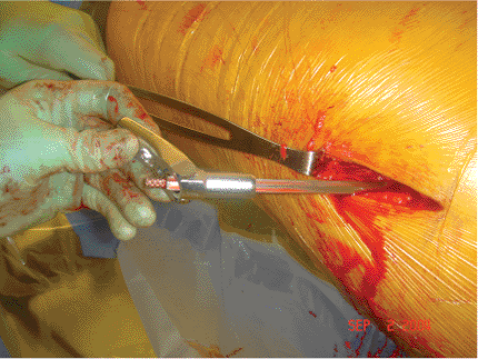
during lag screw insertion (Fig. 16.14). The lag screw is then inserted to within 1 cm of the subchondral bone (Fig. 16.15).
may contribute to malreduction with a sliding hip screw. In most
intertrochanteric fractures, the proximal fragment tends to be
displaced anteriorly. All lag screws are placed in a clockwise fashion.
As the lag screw is advanced on left-sided intertrochanteric fractures,
the clockwise rotation may further displace the fracture, while on the
right side, the screw may help reduce the fracture. This phenomenon was
demonstrated in a retrospective study in which 11 of 30 unstable
left-sided intertrochanteric fractures were found to be malreduced with
an anterior spike, while none of 26 right-sided fractures showed an
anterior spike.
femoral head is confirmed, a two- to four-hole side plate is placed
over the screw (Fig. 16.16). I prefer use of a
two-hole keyed, side plate. In a keyed system, the lag screw is
captured within the barrel such that the screw can slide along the
barrel but cannot rotate. This mechanism theoretically improves
rotational stability of the femoral head and neck better than a
nonkeyed system in which the lag screw can rotate within the plate
barrel. The advantage of a nonkeyed system is that the free rotation of
the plate over the lag screw facilitates plate insertion.
room for sliding within the lag screw/barrel. Loss of sliding
capability may be related to excessive postoperative impaction or
jamming of the lag screw within the plate barrel. Kyle et al, in a
biomechanical
study,
demonstrated that jamming of the lag screw within the plate barrel can
occur when the force of contact between the lag screw and barrel lip is
greater than the sliding forces in line with the lag screw. The amount
of bending of the lag screw is inversely related to the amount of lag
screw-plate barrel engagement and results in impingement of the screw
at the barrel junction. Because bending of the lag screw is more likely
to occur with use of a short-barrel side plate, a regular-length barrel
side plate is preferred for most intertrochanteric fractures.
 |
|
Figure 16.12. Measurement of the guide wire length.
|
 |
|
Figure 16.13. A. Reaming of the femoral neck and head over the guide pin is performed under image intensification (B) to the desired final position of the lag screw.
|
 |
|
Figure 16.14. A. Tapping of the proximal femur under image intensification to the (B) final, seated, lag-screw position to prevent femoral head rotation during lag screw insertion.
|
 |
|
Figure 16.15. Insertion of the lag screw to within 1 cm of the subchondral bone.
|
 |
|
Figure 16.16. Placement of a two-hole side plate over the lag screw.
|
consecutive patients who sustained an unstable intertrochanteric
fracture that a stabilized with a sliding hip screw. In fractures
stabilized with <10 mm of available slide, the risk of fixation
failure was more than three times greater than those fractures with ≥10
mm of available slide. Based on the specifications for the particular
lag screw and side plate used in the Gundle et al study (Synthes DHS
with a 32-mm barrel and 32 lags screw length), Gundle et al advocated
use of a short-barrel side plate when using lag screws of ≤85 mm. This
concern is less with use of the VHS because the VHS has a single
side-plate barrel length of 24 mm and a lag-screw thread length of 22
mm. Even with an 80 mm total lag-screw length, 34 mm (80 – 46 = 34 mm)
would be available to slide.
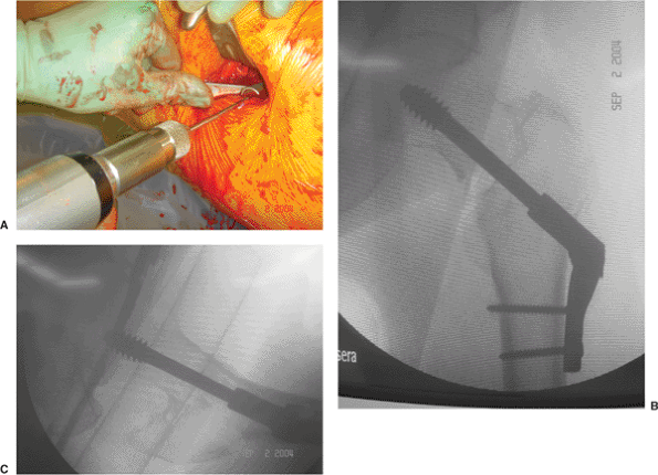
the proximal femur. With the VHS system, if the side plate does not
parallel the lateral cortex, one can adjust the plate angle using a
screw driver to move the mechanism that controls the side plate–barrel
angle (Fig. 16.17). Once the plate has been
inserted and placed against the bone, it is loosely clamped to the
femoral shaft and the fracture is impacted by releasing the traction on
the extremity and gently displacing the femoral shaft toward the
proximal fragment. This impaction maneuver is thought to enhance
fracture stability. The plate-holding screws are then inserted (Fig. 16.18).
The need for a compression screw is determined by direct visualization
of the lag screw within the plate barrel; a compression screw is
inserted if there is risk of postoperative screw-barrel disengagement.
A compression screw is not used routinely because it often loosens
(even during uneventful fracture healing) and can become a source of
lateral thigh pain.
of bed on the first postoperative day and allowed to ambulate with
weight bearing as tolerated. It is difficult if not impossible for
elderly patients to make significant progress in a rehabilitation
program if weight bearing is restricted. In addition, there is little
biomechanical justification for restricted weight bearing after hip
fracture because activities such as moving around in bed and use of a
bedpan generate forces across the hip approaching those resulting from
ambulation. All patients should have thromboembolic and 24 to 48 hours
of broad spectrum antibiotic prophylaxis.
12 weeks, and then at 6 months, 12 months and yearly. At follow-up, an
AP view of the pelvis, and an AP and cross-table lateral of the
fractured hip are taken. Patients initially receive at-home physical
therapy for gait training and range of motion exercises of the hip and
knee; they are then referred to outpatient physical therapy. Once there
is radiographic evidence of fracture healing, muscle strengthening
exercises are initiated.
expected to unite uneventfully. Evaluation of functional recovery
following hip fracture has become increasingly important because
success is measured by return to prefracture levels of function. Forty
percent to 60% of hip fracture patients are able to return directly
home after hospitalization. Factors predictive of a hospital to home
discharge are younger age, prefracture and early postfracture
independent ambulation, ability to perform activities of daily living
(ADLs), and the presence of another person at home. Forty percent to
60% of patients will regain their prefracture ambulatory status within
one year after fracture. The factors associated with regaining
prefracture ambulatory status following hip fracture include: younger
age, male sex, and the absence of preexisting dementia. The vast
majority of patients will require assistance in performing ADLs. Of
those who were independent in ADLs before fracture, only 20% to 35%
will regain their prefracture ADLs independence. The factors reported
to be predictive of recovery of ADLs are younger age, absence of
dementia or delirium in nondemented patients, and greater contact with
one’s social network.
 |
|
Figure 16.17. The side plate is impacted against the lateral cortex of the proximal femur. With the VHS system, (A) if the side plate does not parallel the lateral cortex, (B) one can adjust the plate angle using a screw driver to move the (C) worm gear that controls the side plate–barrel angle.
|
 |
|
Figure 16.18. A. Insertion of the plate-holding screws and (B) final AP and (C) lateral radiographs.
|
is similar to that reported after femoral neck fracture and ranges from
14 to 36%. Most authors agree that the highest risk of mortality occurs
within the first 4 to 6 months following fracture. After the first
year, the mortality rate approaches that of age- and sex-matched
controls who have not sustained a hip fracture. The incidence of wound
infection has decreased significantly with the use of prophylactic
antibiotics; most recent studies have reported an incidence of less
than 3%. Risk factors include urinary tract infection, decubitus
ulcers, prolonged operating time, disorientation that interferes with
proper wound care, and proximity of the incision to the perineum.
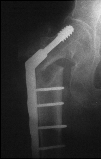
are varus displacement of the proximal fragment with loss of fixation,
malrotation deformity and nonunion. Varus displacement following
internal fixation usually occurs in unstable fractures, with the lag
screw “cutting out” through the anterosuperior portion of the femoral
head (Fig. 16.19). This complication can result
from (a) placement of the lag screw into the anterosuperior aspect of
the femoral head, (b) inability to obtain a stable reduction, (c)
excessive collapse of the fracture such that the sliding capacity of
the device is exceeded, (d) inadequate screw-barrel engagement that
prevents sliding, or (e) severe osteoporosis that precludes secure
fixation. When this complication occurs, management choices include
acceptance of the deformity; a second attempt at open reduction and
internal fixation (ORIF), which may require methylmethacrylate; or
conversion to a unipolar or bipolar endoprosthesis or total hip
arthroplasty. Acceptance of the deformity should be considered in
nonambulatory patients
who
are poor surgical risks. When reoperation is indicated, conversion to a
hemi-arthroplasty or total hip replacement (THR) is usually performed.
 |
|
Figure 16.19. Loss of reduction after surgery with resultant varus displacement of the proximal fragment and screw cutout.
|
rotation of the distal fragment at the time of internal fixation. In
unstable fractures, the proximal and distal fragments may move
independently. In these cases, the distal fragment should be internally
fixed in neutral to slight external rotation. Nonunion occurs in less
than 2% of cases. In some cases, with good bone stock, repeat internal
fixation combined with a valgus osteotomy and bone grafting can be
considered. However, in most elderly patients, conversion to a calcar
replacement arthroplasty will be preferred.
MR, Chrostowski JH, Levy RN. Intertrochanteric hip fractures. In:
Browner BD, Levine AM, Jupiter JB, Trafton PG, eds. Skeletal trauma. Vol. 2. Philadelphia: W.B. Saunders; 1992:1833–1881.
MR, Curtin SL, Lindskog DM, et al. The value of the tip-apex distance
in predicting failure of fixation of peritrochanteric fractures of the
hip. J Bone Joint Surg 1995;77:1058–1064.
BR, Russo PR, Carmen B. Results of intertrochanteric femur fractures
treated with a 135-degree sliding screw with a two-hole side plate. J Orthop Trauma 1999;13(1):5–8.
SH, Mukherjee DP, Ogden AL, et al. A biomechanical study of femoral
neck fracture fixation with the VHS Vari-Angle Hip Fixation System. Am J Orthop 2002;(Suppl 1):22–24.
WY, Han CH, Park JI, et al. Failure of intertrochanteric fracture
fixation with a dynamic hip screw in relation to preoperative fracture
stability and osteoporosis. Int Orthop 2001;25(6):360–362.
KJ, Friend K, Aharonoff G, et al. Weight bearing after hip fracture: a
prospective series of 596 geriatric hip fracture patients. J Orthop Trauma 1996;10(8):526–530.
SW, Wheeler DL, Rider J, et al. Biomechanical evaluation of the dynamic
hip screw with two- and four-hole side plates. J Orthop Trauma 2000;14(5):318–323.
R, Karthikeyan R, Sonanis SV. Dynamic hip screw: does side make a
difference? Effects of clockwise torque on right and left DHS. Injury 2000;31:697–699.