
estimated at 250,000 per year and will double by the year 2040. Fifty
percent of hip fractures are intertrochanteric, of which 50% to 60% are
classified as unstable. These fractures typically occur in elderly
females, with 90% of fractures occurring in patients older than 65
years. The etiology of intertrochanteric hip fractures is typically
attributed to low-energy falls in the setting of osteoporosis.
both the treatment strategy and the surgical outcome. Unstable
fractures have significant disruption of the posteromedial cortex,
including subtrochanteric extension, or are reverse obliquity
fractures. Stable two-part fractures, once reduced, will resist medial
and compressive loads, whereas unstable fractures will have a tendency
to collapse into varus.
unstable intertrochanteric hip fractures and are ideal for
subtrochanteric and reverse obliquity fractures. An additional
indication is an impending or pathologic fracture of the proximal
femur. Multiple studies have indicated that the IMHS offers no
advantage over a sliding hip screw and side plate in a stable fracture
pattern. However, its utilization with stable fractures will provide a
means to improve and streamline one’s technique when dealing with the
more challenging unstable fracture patterns.
neck fractures, deformities of the femoral shaft, and hip ankylosis. An
additional contraindication is the young patient because an excessive
amount of trabecular bone is removed from the trochanteric block to
accommodate these relatively large implants.
intramedullary nail. Implant insertion can be performed in a closed,
percutaneous manner, allowing minimal surgical insult to the fracture
zone and reduced perioperative blood loss. The device functions as an
intramedullary
buttress, effectively reestablishing the mechanical support of the
posteromedial cortex and thus preventing excessive shaft medialization.
By avoiding violation of the fracture zone, the surgeon facilitates
fracture union.
with the affected limb shortened and externally rotated. It is
important to obtain a thorough medical and social history as well as
determine if the patient has an oncologic history. It is equally
important that a complete physical examination is performed with care
to examine the condition of the skin overlying the hip and to rule out
any associated injuries.
generally confirmed with standard anteroposterior (AP) and lateral
radiographs. These radiographs should include at least the proximal
half of the femur because deformities of the shaft may preclude the use
of an intramedullary device. Internal rotation and traction radiographs
can further aid in understanding the pathoanatomy.
intertrochanteric hip fractures is critical to obtaining a successful
postoperative outcome because the patient population is medically
complex. Some issues of particular importance are the patient’s
nutritional status, management of urinary tract infections, hemodynamic
stability, coagulopathy, deep vein thrombosis (DVT) prophylaxis, and
perioperative antibiotics. Typically, optimization should not be
prolonged, as mortality is increased when surgery is delayed beyond 48
to 72 hours from admission.
well as the unaffected hip will help guide appropriate implant
selection with respect to the neck angle, diameter, and screw length.
We typically use a 135-degree neck angle with a 95-mm lag screw. It is
important to note that the IMHS is not designed to fill the canal. A
long stem device should be considered in the setting of a pathologic
fracture or fractures with significant subtrochanteric extension.
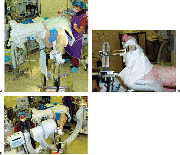
A well-padded post is placed in the perineum. The affected side is
secured to the traction assembly. We prefer to use the heel stirrup and
metatarsal bar as opposed to putting the foot in the Velcro-strapped
boot. The heel and the forefoot are cushioned with an ABD pad, and
heavy cloth tape is used to secure the foot to the stirrup (Fig. 17.1B).
By locking the transverse tarsal joint and dorsiflexing the ankle, we
gain greater control over the extremity for firm traction and
internal/external rotation. The affected extremity is adducted with the
torso shifted away from the surgical side. The unaffected extremity can
be placed in the well leg holder with the knee flexed and the hip
flexed and internally rotated. This allows for unhindered access for
the image intensifier so that lateral radiographs of the fracture zone
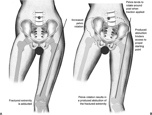
can be obtained (Fig. 17.1C). Unfortunately,
this visualization may occasionally come at a price: There is no
countertraction on the well leg. As a result, when strong traction is
applied to the fracture, the pelvis has a tendency to rotate around the
perineal post. This produces abduction of the operative side and can
significantly hamper achieving the correct starting point, leading to a
varus reduction (Fig. 17.2).
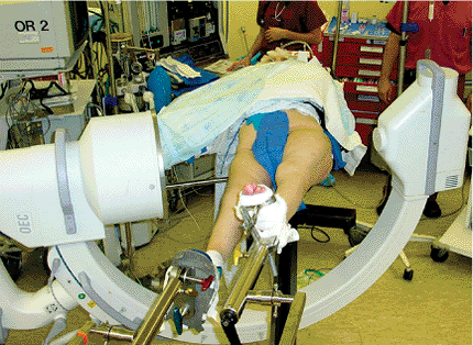
countertraction on the pelvis by placing both extremities parallel in
foot traction. The extremities are “scissored,” with the operative side
slightly flexed at the hip and the well side extended to allow for
lateral plane fluoroscopic imaging (Fig. 17.3).
the table, the extremity is manipulated. The primary goal is to gain
access to the starting point; secondarily, we attempt fracture
reduction. Most stable fracture patterns will reduce with axial
traction and internal
rotation
of the femur. However, unstable intertrochanteric hip fractures may
require different maneuvers, such as slight external rotation. Prior to
draping the field, we confirm that we can see the following areas via
fluoroscopy: the anterior cortex of the proximal femur, the fracture
zone, the anterior neck, the entire circumference of the femoral head,
the posterior neck, and the trochanter.
 |
|
Figure 17.1. A.
In the typical position, the patient is supine on the fracture table with the torso windswept and the affected extremity secured to the traction assembly. The well leg is flexed and internally rotated at the hip to allow for unimpeded bi-planar imaging. B. The foot is secured to the stirrup with the metatarsal bar and held in dorsiflexion. C. Patient is positioned so that a lateral radiograph can be readily obtained. |
acceptable neck-shaft angle to be 130 to 145 degrees. More valgus is
allowed because it reduces the bending forces on the implant and may
offset the limb shortening that occurs with fragment impaction.
Angulation greater than 15 degrees, as seen on the lateral view, is
unacceptable.
surfaces should be prepped in standard sterile fashion. Care should be
taken to prep to the level of the knee in the event that a long nail is
used such that a distal interlocking screw can be placed. We use a
sterile shower-curtain type drape but add an extra sterile layer
proximally to protect against puncture hole contamination from the
instrumentation.
of the guide pin and the IMHS. In addition, this helps reduce
fluoroscreening time. Typically, prior to skin incision, the implant
and insertion jig are preassembled per the preoperative plan. It is
very helpful to insert and partially advance the set-screw that locks
the nail to the sleeve prior to implantation because later it is often
difficult to place through the percutaneous wound (Fig. 17.5).
 |
|
Figure 17.2.
With the application of unopposed traction, the pelvis rotates around the perineal post. The hip abducts, hampering access to the starting point. |
 |
|
Figure 17.3.
Alternate method of positioning with the legs scissored. This position provides countertraction on the pelvis and still allows for lateral plane imaging. |
 |
|
Figure 17.4. Marking of the femoral shaft axis and the tip of the trochanter.
|
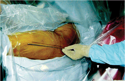
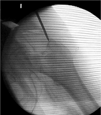
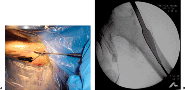
should be verified with bi-planar imaging. Using a freehand technique,
we insert a 3.2-mm guide pin percutaneously (Fig. 17.6),
about 3 to 4 cm proximal to the trochanter, engaging the bone at or
just medial to the tip of the greater trochanter. This location will
counteract the tendency toward varus and increased neck-shaft offset as
well as minimize any damage to the gluteus medius insertion (Fig. 17.7). Based on the lateral view, the guide pin should be centered in the canal (Fig. 17.8A), and based on the AP, it should be aimed slightly medial (Fig. 17.8B).
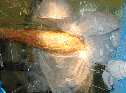
milliliters of local anesthetic with epinephrine proximal to the
greater trochanter. We then make a 2 cm incision and cut down with a
no. 10 blade along the guide pin, through fascia, and directly onto the
greater trochanter (Fig. 17.9).
it is unnecessary to ream to the isthmus. The surgeon must be certain
that the reamer is cutting a channel for the implant rather than simply
displacing the fragments as it passes into the canal (particularly if
the guide pin is in the fracture line). Placing firm medial-directed
pressure on the trochanteric mass, as well as medial/lateral
translational forces applied to the rigid reamer as it is repeatedly
advanced and retracted,
can insure appropriate canal preparation (Fig. 17.11).
Inadequate entrance-site preparation is much more problematic than
generous reaming in this patient population, particularly if one wants
to modify the neck-shaft axis after nail insertion.
 |
|
Figure 17.5. The implant and insertion guide are preassembled. The torque-limiting screwdriver is engaged in the nail.
|
 |
|
Figure 17.6. Percutaneous, freehand insertion of the guide pin at the tip of the greater trochanter.
|
 |
|
Figure 17.7. Ideal starting point just medial to the tip of the greater trochanter.
|
intramedullary canal. Only hand force should be required; hammering
risks iatrogenic fracture (Fig. 17.12). Usually the nail need not be inserted over a guide pin. Bi-planar fluoroscopy should be checked at this point to ensure
that the nail is not exiting the canal through the fracture and that
the nail is seated to an adequate depth. If the nail does not fully
advance but does not appear “tight” on the AP image, the surgeon should
check the lateral image to see if the tip of the nail is impinging on
the anterior cortex because most nail systems do not have a sagittal
bow to the nail. Also, soft tissue should be checked to ensure that it
is not restricting the entrance site. A combination of eccentric
entrance site reaming (primarily anterior), soft-tissue release,
isthmic (flexible) reaming, or implant downsizing will invariably solve
the problem.
 |
|
Figure 17.8. A. Ideal guide pin location on the AP view: centered in the intramedullary canal. B. Ideal guide pin location: centered on the lateral view.
|
 |
|
Figure 17.9. A. Incision is made directly over the guide pin through the skin and fascia. B. The scalpel is advanced to the level of the tip of the greater trochanter.
|
 |
|
Figure 17.10. A.
Insertion of the proximal reamer using the tissue protector sleeve. (We usually do not use the sleeve and minimize soft-tissue trauma by simply running the reamer in reverse until it has entered the bone [see Fig. 17.11].) B. Insertion of the proximal reamer so that the widest part is at the level of the lesser trochanter. |
 |
|
Figure 17.11.
Firm medial pressure is placed to prevent lateral fracture displacement and to assure that a channel for the implant is created. |
 |
|
Figure 17.12. The nail is fully seated in the canal.
|
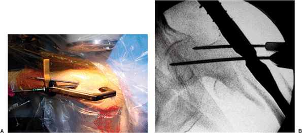
incision and subsequent lag-screw insertion, some systems have a tower
attachment that can be used to preview the position of the guide pin
for the sliding hip screw (Fig. 17.13A).
Through this positioning guide, a 3.2-mm guide pin can be placed
anterior to the patient’s soft tissue. Otherwise, one can estimate the
location and again inject with local anesthetic and make a 2-cm skin
incision. The surgeon should be certain to split through the fascia
lata so that the sleeve can be placed flush against the lateral cortex
of the femur (Fig. 17.13B). Taking into account
the anteversion of the neck, the surgeon should advance the appropriate
guide pin through the jig and nail up into the femoral head.
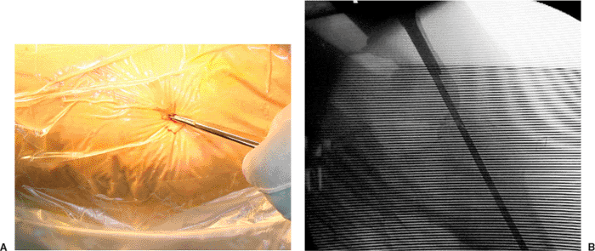
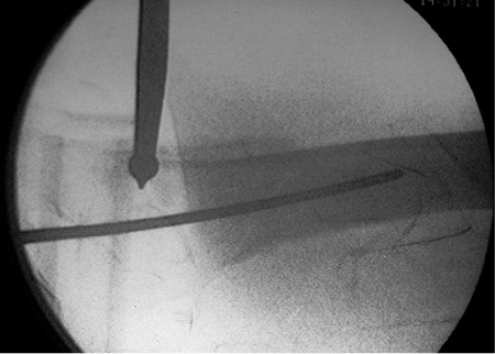
often improve the reduction. On the lateral view, any “sag” or
translation needs to be addressed. Anterior translation of the
insertion jig, and hence the shaft which it controls, is often helpful.
This effect can be enhanced in the setting of a difficult reduction
with percutaneous manipulation of the head-neck fragment (Fig. 17.14).
In particularly difficult fractures, the proximal fragment can be
manipulated and then pinned to the inferior acetabulum. For
interpretation of the AP view, the guide pin acts as an excellent
reference because it is 135 degrees to the shaft. If it is parallel but
simply too superior in the head, the neck-shaft axis is acceptable, and
pin removal with nail advancement and pin reinsertion will solve the
malposition. However, if the neck and guide pin are not parallel, the
fracture is most likely malreduced in varus. The reduction can be
improved with increased traction, or perhaps more effectively, by
abduction of the extremity. With the nail inserted, hip adduction is no
longer mandatory, or necessarily desirable. As long as the entrance
site was adequately reamed, this simple maneuver will increase the
neck-shaft angle without significantly displacing the medial fracture
line or increasing offset.
 |
|
Figure 17.13. A. Tower attachment with guide pin allows preview of lag screw placement prior to skin incision. B. Jig assembly for guide pin placement into the head.
|
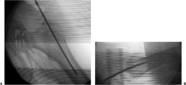
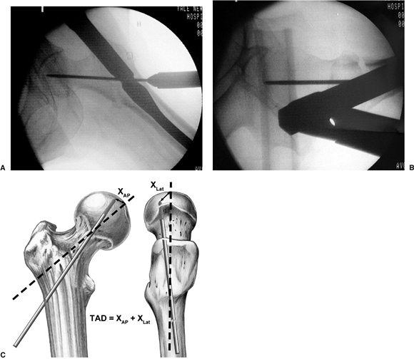
guide pin is inserted centrally and very deep using both the AP and
lateral x-rays for guidance (Fig. 17.15A,B).
The guide pin placement should then be confirmed to have the optimal
tip-apex distance (TAD) of 5 to 10 mm from the articular surface of the
femoral head (see Fig. 17.15C).
placed guide pin, we add an auxiliary stabilizing pin for all unstable
fractures (Fig. 17.16). This auxiliary pin is
directed through the jig such that it avoids the path of the lag screw
and locks the jig to the head-neck fragment. The auxiliary pin serves
as an antirotation device during screw insertion as well as an
independent stabilizer should the guide pin be inadvertently removed
while the surgeon is reaming for the lag screw.
femoral head, we ream 5 mm short of the subchondral bone. We take the
instability of the fracture into account in setting the reamer depth
because markedly unstable fractures are often found to be distracted
following reduction maneuvers and will shorten with the compression
provided by the reamer itself. Reamer progress is monitored with spot
fluoroscopic images to identify inadvertent binding and advancement of
the guide pin as well as to prevent overpenetration. An obturator
should be used during reamer removal to prevent loss of the guide pin.
We seldom use a tap because of the bone quality typically seen in this
patient population.
 |
|
Figure 17.14. A ball-spike pusher is applied percutaneously to facilitate fracture reduction.
|
 |
|
Figure 17.15. A. Appropriate guide pin placement on the AP x-ray. B. Appropriate guide pin placement on the lateral x-ray. C. The technique to measure TAD.
|
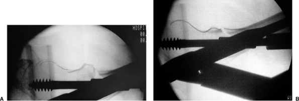
aspect of the fully seated screw lies 5 to 8 mm recessed into the
centering sleeve, exactly as one would do when using a barrel and side
plate. For a 135-degree nail, a 95-mm screw is almost always
appropriate. The lag screw is then inserted over the guide pin (with
the centering sleeve mounted onto the jig for systems that employ this
sliding adjunct). Once the lag screw has reached the appropriate depth (Fig. 17.17A)
and the reduction is verified, the centering sleeve should be advanced
though the lateral cortex and into the nail using the sleeve pusher (Fig. 17.17B).
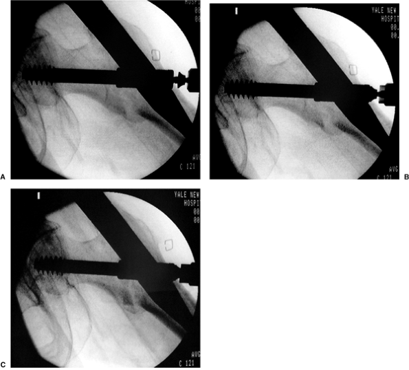
the screw is seated into the dense subchondral bone. On right hips,
screw insertion tends to extend the fragment, which often helps correct
mild extension deformities at the fracture. However, for left-side
fractures, the clockwise seating of the screw flexes the hip and
worsens any extension deformity at the fracture. We scrutinize the
fracture on the lateral fluoroscopic image while slightly rotating the
screw insertion wrench back and forth (which controls the head-neck
fragment) to identify the optimum reduction (Fig. 17.18). The reduced position is then maintained while the AP image is obtained to confirm the reduction. The sleeve is then
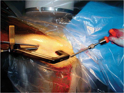
locked to the nail when we tighten the previously inserted set screw with the torque-limited driver (Fig. 17.19). This locks in the rotational reduction but allows unimpeded sliding of the screw in the sleeve.
 |
|
Figure 17.16. A. Certain implant systems provide a targeting attachment to place the auxiliary stabilizing pin. B. An auxiliary stabilizing pin is added to help control rotation. It is placed out of the path of the lag screw.
|
 |
|
Figure 17.17. A. The lag screw is seated to the appropriate depth. Image was taken prior to centering of sleeve insertion. B. The centering sleeve is advanced through the lateral cortex and into the nail using the sleeve pusher.
|
 |
|
Figure 17.18. A. Lag screw insertion in a left hip showing worsening of extension deformity. B. Rotation of the screw results in fracture reduction.
|
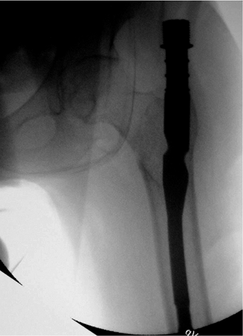
from the extremity prior to considering a distal interlocking screw. We
then assess rotational stability by securing the distal extremity and
follow by gently rotating the insertion jig. If the femur moves as a
unit, we do not distally lock (Fig. 17.21). If
there is any question of motion, a single screw is placed in the
dynamic slot using the alignment jig. For length-unstable fractures,
two interlocks are placed through the insertion jig, or for the longer
nails, by freehand techniques.
place a deep, strong suture to close the tensor fascia proximal to the
trochanter at the nail insertion site. This proximal wound is at risk
of contamination from a disoriented elderly patient’s wandering fingers
(Fig. 17.22). A dry sterile dressing is applied with care in consideration of the elderly patient’s fragile skin.
 |
|
Figure 17.19. The sleeve is locked to the nail by tightening the previously inserted set screw with the torque-limited driver.
|
 |
|
Figure 17.20. A–C. A demonstration of compression screw insertion. Note how the fracture reduces with the applied compression.
|
no difference was demonstrated in comparing an IMHS versus compression
hip screw (CHS) with respect to complications. However, we were able to
demonstrate decreased fluoro time, decreased operative time, and
decreased blood loss. In a prospective study, Hardy et al demonstrated
that patients receiving an IMHS had improved early mobility and
decreased limb shortening. As surgeons have become more familiar with
instrumentation techniques and newer generation nails are released, the
rate of surgical complications reported in the literature has decreased.
antibiotic prophylaxis, generally with a first-generation
cephalosporin. Prophylaxis against DVT is carefully considered
with
a combination of sequential compression devices and pharmacologic
prophylaxes. All patients are allowed to weight bear to tolerance,
although we may limit the amount of ambulation in the cognitively
impaired patients with severely unstable patterns. Patients will
ambulate with a physical therapist beginning on postoperative day 1 or
2. Patients are typically discharged to a short-term rehabilitation
facility on postoperative day 3 or 4. We see patients at 10 to 14 days
to rule out wound healing problems and at 6 and 12 weeks to confirm
clinical and radiographic union. Patients who sustain low-energy
intertrochanteric hip fractures should be evaluated and treated for
osteoporosis.
 |
|
Figure 17.21. A,B. AP and lateral postoperative radiographs.
|
surgical technique and appropriate implant selection. The most common
complication is implant cutout. A varus neck-shaft angle universally
leads to an increased TAD and an increased offset when an
intramedullary device is used. In a study performed by the primary
author, cutouts were shown to be related to implant position as
measured by the TAD. At TAD <25 mm,
failure rates approach zero, but at TAD >25 mm, the chances of failure increase rapidly.
 |
|
Figure 17.22. The two small skin incisions with staple closure.
|
periprosthetic fracture, painful hardware, and nonunion. A number of
techniques, such as conversion to a hip replacement, re-osteosynthesis
with a long stem IMHS, or open reduction and internal fixation (ORIF),
can be used to address these problems. Fortunately, these complications
are uncommon with proper surgical technique and new generation devices.
MR, Curtin SL, Lindskog DM. Intramedullary versus extramedullary
fixation for the treatment of intertrochanteric hip fractures. Clin Orthop 1998;348:87–94.
MR, Curtin SL, Lindskog DM, et al. The value of the tip-apex distance
in predicting failure of fixation of peritrochanteric fractures of the
hip. J Bone Joint Surg Am 1995;77:1058–1064.
DC, Descamps PY, Krallis P, et al. Use of an intramedullary hip-screw
compared with a compression hip-screw with a plate for
intertrochanteric femoral fractures: a prospective, randomized study of
one hundred patients. J Bone Joint Surg Am 1998;80: 618–630.