
are becoming an increasingly common problem encountered by orthopedic
surgeons. Not only is the number of total joint replacements performed
increasing annually, but the expected longevity of patients who undergo
these procedures is also increasing. These fractures may occur
intraoperatively or postoperatively. The incidence of periprosthetic
hip fractures is generally higher in uncemented (4.1% to 27.8%) than in
cemented (<3%) prosthesis. Risk factors for intraoperative fractures
include rheumatoid arthritis, cementless arthroplasty, metabolic bone
disease, complex deformity, and revision surgery. Risk factors for
postoperative fractures include weakened bone secondary to
osteoporosis, stress risers, empty screw holes, eccentric reaming,
cortical perforations, stem tip protrusion, loose implants, and
osteolysis.
acetabular or femoral side, most of the literature discusses fractures
on the femoral side of a total hip arthroplasty (THA) or around the
femoral side of a total knee arthroplasty (TKA). In the first section
of the chapter, we describe techniques for repairing periprosthetic
fractures adjacent to the femoral component of a total hip
arthroplasty. We address fractures associated with TKA in the second
part of this chapter.
treatment of THA. Johannson classified periprosthetic femur fractures
into type I (proximal to the stem tip), type II (around the tip), and
type III (distal to the tip) categories. In a primary cementless
implant the majority of intraoperative fractures are type I with the
minority being types II or III. Duncan and Masri’s classification
roughly correlates with Johannson’s classification: type A
(peritrochanteric), B (tip), and C (distal) fractures. The incidence of
these is reported to be 4%, 87%, and 9% respectively for types A, B,
and C. Type A fractures are subdivided into A(G) (greater trochanteric)
and A(L) (lesser trochanteric) fractures, which are generally treated
nonoperatively.
B fractures are divided among B1 (stable prosthesis, 18%), B2 (loose
prosthesis requiring stem revision, 45%), and B3 (marked osteopenia,
37%). Types I and A are the most common intraoperative fracture and can
be treated with cerclage wiring. Types II and B generally require a
plate, allograft, and cables. Types III and C can generally be treated
without regard to the prosthesis if they are sufficiently distal.
correcting risk factors that are reversible; avoiding intraoperative
techniques that create stress risers, such as eccentric reaming;
performing routine surveillance x-rays to check for osteolysis; and
revising prostheses when progressive osteolysis is presented. It also
calls for aggressive treatment for patients with osteoporosis.
level of function. In general, surgical treatment is preferred except
for the high-risk surgical patient. Although nonoperative treatment is
associated with high union rates, it exposes the patient to risks
associated with prolonged bed rest and greater rates of malunion.
Nonoperative treatment may be appropriate for the stable type I or A
fracture noted postoperatively or perhaps for a minimally displaced
type II or III fracture.
operatively. Treatment options for an intact prosthesis include
cerclage wiring in high fractures and the use of plating and cortical
struts in low fractures. Occasionally, only wires or cables are used
for a very long spiral fracture that is minimally displaced. In
general, however, some combination of cables, plates, and strut
allografts is used. We have found that either two struts or a
combination of one plate and one strut have proven to be the strongest
constructs tested in torsion and bending. Any defects or stress risers
created (tip of stem, cortical perforation, etc.) should be bypassed by
a strut or plate by at least two cortical diameters because this
strategy restores 84% of the original strength of the bone. With loose
implants, treatment options include removal of the implant while
maintaining as much bone stock as possible. A loose implant should then
be revised with a longer stem and cortical strut grafts.
Lewallen et al classified these into type I (stable cup) and type II
(unstable cup). Type I fractures may be treated nonoperatively with
good healing rates through use of a brace or spica cast. Type II
fractures should be treated with cup revision.
of the fracture, stability of the prosthesis, and the quality of the
bone. The standard radiographs include a low anteroposterior (AP)
pelvis x-ray centered about the pubis, as well as an AP and frog or
cross-table lateral of the affected limb. If acetabular osteolysis is
seen or suspected, then Judet films should be obtained to assess the
area and extent of bony peri-acetabular deficiency. In some patients,
additional information can be gained from scanograms to assess leg
lengths. Identification of prosthesis type is necessary if special
femoral-extraction devices may be needed. The preoperative assessment
also includes range-of-motion and neurovascular statuses so that any
preoperative deficiencies and the patient’s leg lengths can be
documented. If a plate is to be used, we template the fracture and
determine the length of side plate needed to bridge the fracture site
adequately; we will always err on using a plate that is too long.
Occasionally a plate must span the entire length of the femur.
can identify the surgical approach used and the type, size, and
modularity of the prosthesis implanted. Preoperative templating is
necessary to assess the length and diameter of the prosthesis when
revision arthroplasty is needed. As a general rule, the surgeon should
make sure that all stress risers, such as cortical windows and holes in
the diaphysis, are bypassed with a stem that is at least two times the
shaft diameter. Areas of transition between stem tips and plates or
stem tips and stem tips should be avoided. Cortical strut grafts over
holes, windows, fractures, and in areas of transition are beneficial.
Most nonmodular stems are less than 265 cm, so the use of longer
modular stems may be needed. The stem diameter should be large enough
so the fit helps splint the fracture and allows an adequate surface for
bone ingrowth and
good
rotational control of the prosthesis. Preoperative templating is
crucial because it allows the surgeon to anticipate the need for all
implants.
differential C-reactive protein (CRP), and erythrocyte sedimentation
rate (ESR) should be obtained. If any of these parameters are elevated,
then a hip aspiration under fluoroscopic guidance should be preformed.
Because revision surgery generally entails a relatively high blood
loss, patients should be typed and cross matched for blood replacement
in case it is needed. We do not routinely have patients predonate blood
and frequently use a cell saver.
is routinely inserted, particularly if an epidural anesthetic is
administered. The patient is placed in the lateral decubitus position,
affected side up, on a radiolucent table with the affected hip and leg
draped free. A lateral positioner is used, and all bony prominences are
padded. The wider posterior portion of the holder abuts the posterior
iliac crest, and the narrow anterior portion should come up directly
against the anterior–superior iliac spine. The common error is to place
the anterior positioner too distal, impeding full-hip flexion. The
knees and the feet are lined up to use as a gauge for leg lengths. The
entire lower extremity, hip, and pelvis are prepped and draped.
proximal femur, a Verbrugge clamp is placed around the proximal femur
just prior to surgeon impact on an uncemented femoral stem. Should a
fracture occur, it will likely be nondisplaced, and evidence has shown
that it is unlikely to influence the long-term outcome of the joint
replacement. When the fracture is recognized, one or more cerclage
wires or cables are sufficient. If it is displaced, then it is reduced
and
cerclage wires are used (Fig. 45.1).
 |
|
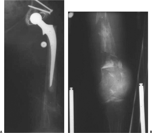
Figure 45.1. Type I periprosthetic femur fracture (nondisplaced calcar crack) treated with a single Luque wire.
|
a long-stem revision with allograft struts is used to bridge the tip of
the stem and fracture site. Cortical perforations are used as needed to
extract the old prosthesis.
incision to minimize blood loss and define the plane between the
iliotibial band and the vastus lateralis. This incision can be
difficult to make due to scarring, but developing this layer will allow
easier placement of retractors and facilitate closure. Electrocautery
is used while the surgeon works to stay on bone until the neck of the
prosthesis is identified.
culture and gram stain. Multiple fluid and tissue cultures are obtained
and sent to the laboratory with every hip revision surgery. Infection
can be a cause of prosthesis loosening and subsequent fracture.
acetabulum can be adequately visualized. The proximal femur is
skeletonized to allow sufficient mobility for stem extraction and
adequate acetabular exposure. A saw or osteotome is used to remove any
bone from the greater trochanter that overhangs the lateral aspect of
the prosthesis. Failing to remove the bone will result in a greater
trochanteric fracture when the stem is removed.
addressed. The goal is to reduce and stabilize the fracture. The
midlateral incision should be extended distally past the fracture. The
vastus split is facilitated by blunt dissection in line with its
fibers, and care is taken to clamp and cauterize the perforators. The
fracture is identified and reduced with minimal stripping, and multiple
Verbrugge clamps are carefully placed. The femur may then be reamed and
broached, and the femoral component tried at this time. The legs are
assessed for length and stability.
suture in the skin just superior to the incision and a second marker
stitch in the greater trochanter. Second, both knees and feet are
aligned and checked for any length discrepancies. Third, with the trial
component in place, the knee is flexed so the surgeon can check for
quadriceps tightness. Occasionally, fluoroscopy is used to check the
fracture reduction, the stem for length, and the percentage of canal
fill. One or two cortical struts should be contoured to the femur
through use of a
high-speed
burr. The goal is to minimize the concavity of the graft so the fit
between the graft and the femur is intimate. Wires or cables are passed
first before the struts to facilitate ease of passing the wires. With
the femoral trial still in place, a cortical strut graft is applied
laterally to the anterior on the femur, and if needed, it is applied
medially to the anterior on the femur; the graft location is dependent
on the fracture pattern and the quality of bone. The allograft struts
are secured with multiple wires or cables spaced at least 3.0 cm apart (Fig. 45.3).
The strut should extend distal to the fracture at least 2.5 times the
shaft diameter to enhance fixation and prevent propagation of the
fracture. Securing the cortical struts will help prevent fracture
displacement and propagation with seating of the final implant. In most
cases, it is best to reduce the fracture and use the long-stem implant
like an intramedullary nail to fix the fracture. Bone struts are
applied after implanting to reinforce fracture fixation and rebuild
bone stock. We prefer Luque wires because they are relatively
inexpensive and will not cut through the bone like cables. The twist of
the Luque wire should be directed posteriorly where its prominence
cannot be felt. If there are risk factors for delayed union or
nonunion, bank bone graft is placed at the fracture site. The final
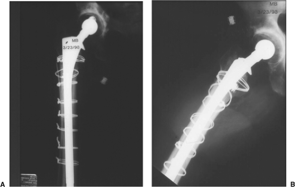
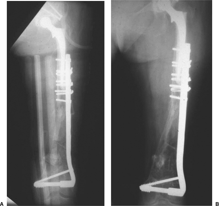
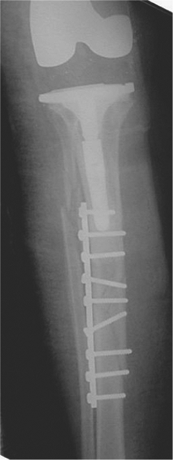
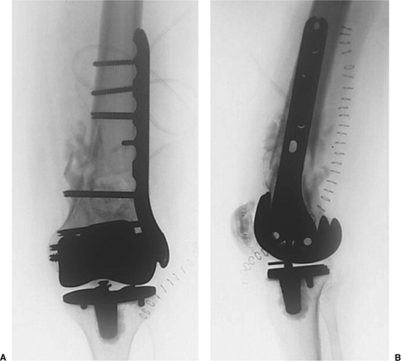
prosthesis is then seated. (Fig. 45.4), and leg lengths and stability are once again checked.
 |
|
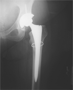
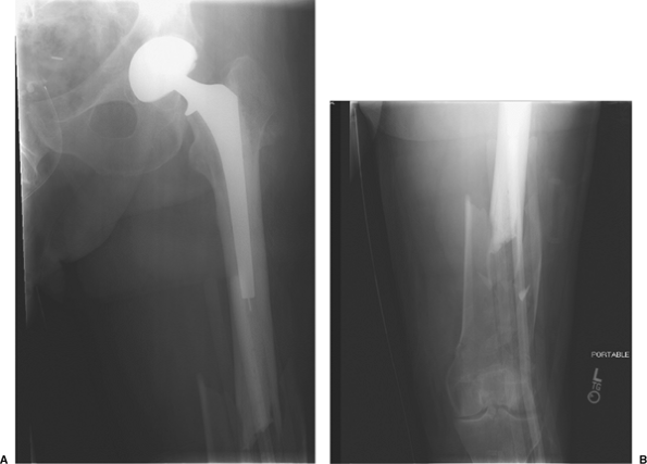
Figure 45.2. Type II periprosthetic femur fracture originating around the tip of a loose stem.
|
 |
|
Figure 45.3. Allograft cortical struts around the proximal femur secured with multiple Luque wires.
|
Dressings are placed with compression around the thigh. Thromboembolic
devices and sequential compression devises are placed in the operation
room. An abduction pillow is used. Postoperatively, AP pelvic as well
as AP and lateral femur films are obtained.
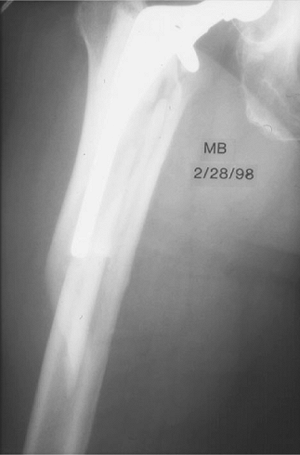
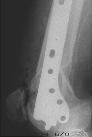
complete, a standard lateral approach to the femur is performed on a
type III fracture with stable prosthesis (Fig. 45.5).
The vastus lateralis is dissected in line with the skin incision, and
the perforating vessels are identified. The fracture site is identified
while great care is taken to minimize stripping. The medial soft
tissues must not be disturbed. The fracture is reduced and
provisionally stabilized with clamps. For most fractures distal to an
implant, plate fixation is preferred. In very distal fractures, a
dynamic condylar screw and side plate are often chosen.
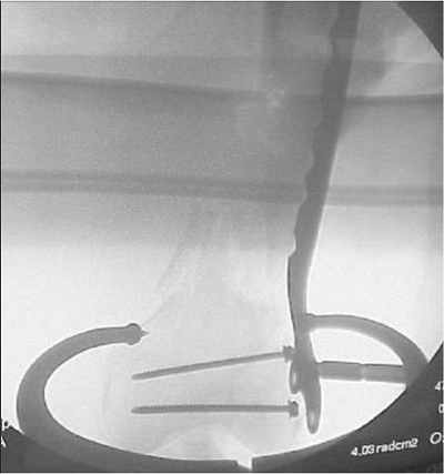
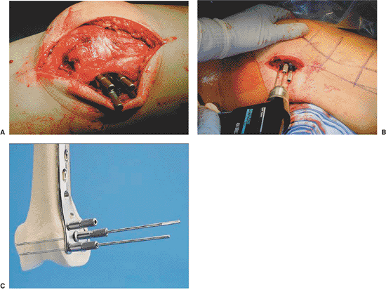
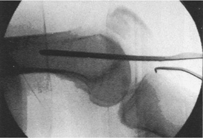
the guide pin for the screw is drilled into the lateral condyle such
that it is parallel with the trochlear notch in the axial plane (Fig. 45.7)
and parallel with the distal tips of the femoral condyles in the AP
plane. This guide wire is 2 cm proximal to the distal ends of the
condyles and slightly anterior to the midline on the lateral view (Fig. 45.8).
The guide pin is overdrilled with the cannulated reamer and the screw
is inserted. To keep the side plate aligned with the lateral cortex, a
Kirschner (K) wire is placed into a screw hole proximally during the
early part of this process. The side plate is
attached
and the shaft screws are inserted distal to the fracture site. An
allograft strut is applied to the anterior cortex with minimal
stripping and held in place with cerclage wires rather than cables.
Proximal to the fracture site, these cables will also hold the end of
the side plate onto the bone (Fig. 45.9).
 |
|
Figure 45.4. AP (A) and lateral (B) radiographs of final revision construct with long-stem implant, struts, and multiple Luque wires.
|
 |
|
Figure 45.5. Proximal AP (A) and distal AP (B) radiographs of a type III (distal fracture with a stable prosthesis).
|
 |
|
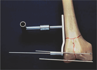
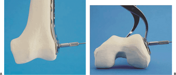
Figure 45.6.
The 95-degree guide is placed on the lateral distal femur with one pin placed in front of the condyles and one pin placed at the distal tips of the condyles. This indicates the correct guide pin direction in two planes. |
 |
|
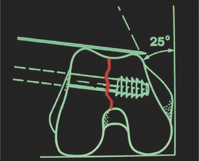
Figure 45.7.
The anterior pin indicates the orientation of the trochlear notch. Central guide pin and screw placement should parallel this pin. |
 |
|
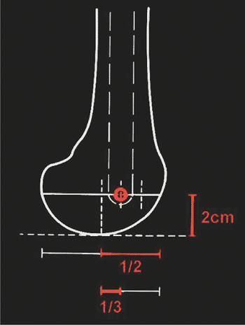
Figure 45.8.
In the lateral view, the guide pin should be 2 cm proximal to the distal tips of the condyles and slightly anterior to midline on the lateral fluoroscopic view. |
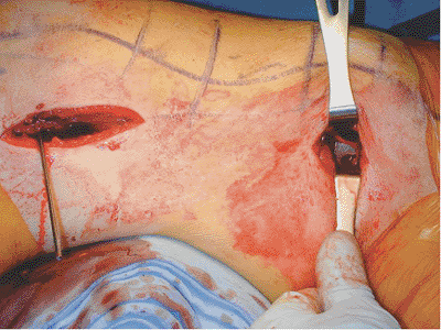
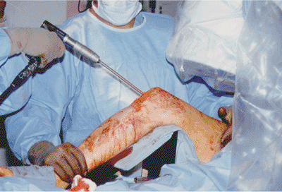
through a bridge technique or indirect reduction to avoid stripping of
the comminuted fracture fragments. It is amenable for those situations
where the stem is solidly fixed and one simply needs to fix the
fracture site (Fig. 45.10). The goal is to
place multiple screws in the distal fragment to maximize purchase in
the short distal fragment with fixation proximally through use of
either cables or unicortical, short, locking screws placed through the
bone and around the stem (Fig. 45.11).
abduction pillow is utilized. Thromboembolic devices are placed while
the patient is in the operating room. In the recovery room, an AP
pelvis as well as full-length AP and lateral femur radiographs are
obtained. Patients are mobilized out of bed on the first postoperative
day to facilitate rehabilitation and to minimize the risk of deep
venous thrombosis (DVT).
weight bearing, overseen initially by a physical therapist, for the
first 6 to 12 weeks, followed by progressive weight bearing as
tolerated. Knee range of motion is encouraged. Drains are usually
removed on the second
postoperative
day or when the drainage falls below 30 cc per 8-hour shift. Broad
spectrum antibiotics are used for 5 days or until the cultures are
negative. Patients are placed on both mechanical and pharmacologic
prophylaxis for DVT. Sequential compression devices (SCDs) and an
enoxaparin are used postoperatively, followed by 4 to 6 weeks of daily
aspirin upon discharge.
 |
|
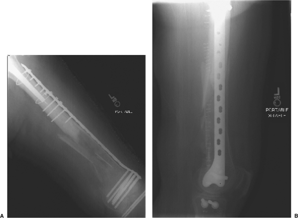
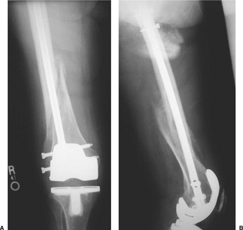
Figure 45.9. AP radiographs immediately postoperative (A) and after final healing of the fracture (B).
|
 |
|
Figure 45.10. AP radiographs of the proximal (A) and distal (B) femur indicating a periprosthetic, distal, femur fracture with a stable-appearing stem.
|
weeks, 3 months, 6 months, and 1 year. AP pelvis as well as AP and
lateral radiographs of the femur are taken at each follow-up visit.
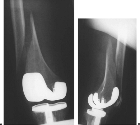
concern. The incidences range from 0.3% to 2.5% of patients. Risk
factors include osteopenia, anterior femoral-cortex notching during
implantation, the use of a constrained prosthesis, and neurologic
disorders.
Radiographs
of periprosthetic femur fractures above a TKA indicate a notched,
anterior, femoral cortex in 40% to 52% of cases. Although no
classification system is widely used, Rorabeck has classified these
injuries into type I (nondisplaced, intact TKA), type II (displaced,
intact TKA), and type III (prosthesis loose/failed).
 |
|
Figure 45.11. AP (A) and lateral (B)
radiographs depicting the final construct with locking, distal, femur plate with proximal, unicortical, locking screws through one cortex and the cement mantle. |
with a 16% nonunion rate. With the use of retrograde nails and locked
plates, success rates have dramatically improved. Treatment options
include closed immobilization, plating, intramedullary (IM) nailing,
and revision to a stemmed prosthesis. Nonoperative treatment is
reserved for nondisplaced fractures and the debilitated elderly
patient. However, there is a 50% decrease in ambulatory status and a
high incidence of varus malunion. Plate fixation traditionally required
that bone stock be sufficient for screw placement. With the
introduction of locked plating, stable fixation in poor bone stock can
be achieved. With comminuted supracondylar fractures, indirect
reduction is recommended, and the fracture site is bridged with screws
out of the zone of injury.
semiconstrained femoral component works well. It is minimally invasive,
load sharing, and less expensive; however, sufficient distal bone is
necessary. In general, if the prosthesis is solidly fixed, one may fix
the fracture by plates or nails. However, if the prosthesis is loose or
comminution is extensive, revision arthroplasty is indicated. This
requires careful prosthesis removal to avoid excess bone loss and use
of a long-stemmed prosthesis as well as bone graft.
common and can be treated nonoperatively with patella tendon bearing
(PTB) casting and bracing when nondisplaced. Open
reduction
and internal fixation (ORIF) with plate and screws is used with
displaced, unstable, periprosthetic, tibial-shaft fractures (Figs. 45.12 and 45.13).
 |
|
Figure 45.12.
Injury AP film of a periprosthetic tibial-shaft fracture below a stable implant. The fracture was considered displaced and unstable. |
 |
|
Figure 45.13. Postoperative AP film depicting plate and screw osteosynthesis of the fracture.
|
of the affected side. The presence of a femoral stem of a THA proximal
to the knee replacement, severe bowing or other deformity of the
femoral shaft, fracture pattern, and location may influence treatment.
Furthermore, the configuration of the femoral component of the total
knee must be ascertained. In general, the space between the flanges of
a cruciate-retaining femoral component will allow reamers and placement
of a retrograde nail of adequate diameter to pass. For most “boxed” or
posterior-stabilized femoral components, IM fixation is impossible and
instead plate fixation should be used. Some boxed femoral components,
however, have a removable cover to allow insertion of the reamers and
nail.
a large bump or a radiolucent triangle is used to elevate the leg and
aid in reduction. In this way, the sagittal angulation of the fracture
can be adjusted by moving the position of the bump. Through a small,
distal, longitudinal incision over the lateral femoral condyle, a
locking plate is passed from distal to proximal and slid submuscularly.
A clamp or K wire is passed through a screw or pin hole at the proximal
tip of the plate to maintain alignment of the plate on the femoral
shaft. Although the surgeon may be tempted to use a shorter plate, if
the segment is extensively comminuted, longer plates are recommended. A
guide wire is passed through the central screw hole in the distal
portion of the plate and passed into the condyles such that it is
parallel to the trochlear notch in the axial plane and parallel to the
distal tips of the condyles in the AP plane (Fig. 45.15). A Verbrugge clamp can be placed around the plate and condyles distally when necessary (Fig. 45.16).
Image intensification is utilized as is direct visualization for proper
rotational alignment of the plate on the lateral condyle (Fig. 45.17).
For rotational control, the plate should be secured to the condyles
with several wires prior to insertion of the first screw (Fig. 45.18).
screws are inserted. The fracture reduction is fine-tuned with the
assistance of a bump or triangle to adjust sagittal and coronal
alignment. Once satisfactory reduction is confirmed, multiple
(percutaneous) proximal screws are placed. Locking screws do not
influence fracture reduction; therefore, the reduction
must
be obtained before placement of locking screws, which can be placed
through small percutaneous incisions along the shaft or through the
small proximal incision made earlier to hold the alignment of the plate
on the shaft (Fig. 45.19).
The clamps and K wires are removed, and final position is checked with
fluoroscopy. Postoperative long cassette films are necessary to show
limb alignment (Fig. 45.20).
 |
|
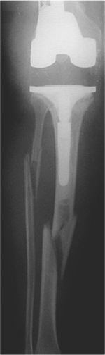
Figure 45.14. Periprosthetic, supracondylar, femur fracture above a stable total knee arthroplasty.
|
 |
|
Figure 45.15. The central guide wire should be parallel to both the distal tips of the condyles in the AP plane (A) as well as the anterior tips of the condyles in the axial plane (B).
|
 |
|
Figure 45.16. A clamp is used to hold the plate to the distal femur.
|
 |
|
Figure 45.17. The lateral view should be checked to ascertain that the plate is aligned with the femoral shaft.
|
 |
|
Figure 45.18. A–C. Three wires are inserted into the distal femur through locking guides threaded into the plate.
|
distal, bone stock is present, retrograde nailing is an attractive
alternative technique (Fig. 24.21). The surgeon must first determine if
the opening in the femoral component of the total knee is large enough
for a nail to be safely inserted. Also, full-length femur films should
be obtained so that the surgeon can identify whether an implant in the
proximal femur or hip is also present. The knee is flexed over a
radiolucent triangle. A 3-cm incision just medial to the patellar
tendon is made, and a small arthrotomy is made. Under fluoroscopic
control, a small, threaded, guide pin is inserted at the anterior edge
of the intercondylar notch at the tip of Blumensaat’s line on the
lateral view and slightly medial to the midline on the AP view (Figs. 45.22 and 45.23).
With a large-diameter cannulated drill, the distal femur is opened with
the surgeon taking care to protect the patellar tendon during the
process.
insertion. The typical deformity is extension of the distal fragment,
which can be corrected by shifting the apex of the triangle slightly
proximal to let gravity pull the distal fragment downward into flexion.
A ball-tipped guide wire is inserted and the femoral canal is reamed
(see Fig. 45.21B). Once sufficient
cortical chatter is encountered, a nail 1 mm smaller than the last
reamer is selected, and the proper nail length is determined. The
proximal tip of the nail must extend at or just above the lesser
trochanter. The distal interlocking screws are inserted first with the
surgeon achieving as many points of fixation distal to the fracture
site as possible. The fracture reduction is checked again with
fluoroscopy. The proximal anterior-to-posterior interlocking screws are
inserted using a freehand technique. The final result is shown in Figure 45.24.
 |
|
Figure 45.19.
A small incision may be made at the tip of the plate to hold the plate onto the bone for rotational control or to place a standard nonlocking screw to approximate the bone and plate. |
 |
|
Figure 45.20. AP (A) and lateral (B) radiographs of the final construct with proximal and distal screws; the middle portion around the fracture is undisturbed.
|
 |
|
Figure 45.21. AP (A) and lateral (B) views of a periprosthetic femur fracture with poor bone stock.
|
 |
|
Figure 45.22.
This lateral c-arm view of guide pin placement for a different patient’s fracture indicates correct placement at the tip of Blumensaat’s line. |
 |
|
Figure 45.23.
After guide pin placement and overdrilling for entry, a ball-tipped guide wire is placed across the fracture. This is left in place as the fracture is reamed. |
 |
|
Figure 45.24. AP (A) and lateral (B) views of the fracture treated with retrograde intramedullary rodding.
|
side for 6 weeks postoperatively or until callus formation is seen on
the radiographs, at which time partial weight bearing can be initiated.
Routine DVT prophylaxis, including both mechanical and (if no epidural
is present or no specific reason is indicated, do not use it)
pharmacologic agents are used. A knee immobilizer is used for comfort,
and patients are mobilized on the first postoperative day.
CH, Smith PN. Fractures of the femur, tibia, and patella after total
knee arthroplasty: decision making and principles of management. Instr Course Lect 1998;47:449–458.