
-
Scheduling surgery
-
Prepare the patient
so that the risks, goals, and benefits of the selected procedure are
understood. The patient or legal next of kin should know the nature of
the patient’s condition, the nature of the proposed treatment, the
alternative treatments, the anesthetic risks, the anticipated
probability for success, and the possible risks. Explain the
postoperative dressings, casts or splints, exercise program, and other
special requirements. When the patient has been so informed and has all
questions answered, obtain a signed operative permit. -
Review the technique
of the proposed operation. At the time surgery is scheduled, be
confident that the patient’s condition meets the appropriate
indications for the proposed surgery. Know the anatomy and the surgical
approaches involved in the selected surgical procedure. Carefully plan
the procedure with the proper alternatives to reduce the length of time
the wound is open. Be sure that all special equipment, implants,
assistance, and time are available as expected. Complete any necessary
templating of roentgenograms and preoperative planning drawings (1).
-
-
Before surgery
-
Patient preparation.
Check to make sure the physical examination, chest roentgenogram,
electrocardiogram, hematocrit, and other indicated preoperative studies
do not contraindicate surgery. Obtain a preoperative consultation from
a specialist in internal medicine for all patients with unstable
medical conditions. Order blood, tetanus prophylaxis, and special
medications as indicated. If an extremity operation is planned, be sure
that the nails are properly trimmed and cleaned. Have the patient,
family, and support system begin planning early for postdischarge or
postoperation disposition needs, such as transportation home,
wheelchairs, hospital beds, wheelchair access to the home, and commodes. -
Antibiotics (2)
-
Preoperative antibiotics
should be administered for surgery that is associated with a high risk
of postoperative deep wound infection, that is, when any implant is
inserted, the operation results in a hematoma or dead space, the
anticipated operating time is greater than 2 hours, or the surgeon is
operating on bones, joints, nerves, or tendons. Various studies have
shown immediate preoperative and postoperative antibiotics to be
beneficial with surgery involving musculoskeletal tissues (2,3,4). See Chap. 1
for utilization of antibiotics with open wounds. The duration of
antibiotic therapy can be limited to 24 hours postoperatively without
increasing the risk to infection. -
The timing of the antibiotic therapy is as important as dosage.
Ideally, the antibiotic level should be highest when the tourniquet is
inflated or the surgical hematoma (potential culture medium) is formed.
Thus, the antibiotics must be given before surgery.
Because the highest blood levels with intravenous (IV) administration
are achieved immediately, the ideal time to give IV antibiotics is when
the patient is in the preoperative area or operating room during the
10- to 15-minute period just before the tourniquet is
P.154
inflated
or before the surgical incision is made. Some surgeons who believe that
the tissue concentration of antibiotics is more important than the
blood levels administer the first dose approximately 2 to 6 hours
before surgery. Either way, the antibiotics are readministered at the
recommended intervals throughout the operative procedure except when a
tourniquet is used. The surgeon must also be aware of the effect of
blood loss on the antibiotic levels. If the blood loss equals one half
of the patient’s volume, then approximately one half of the effective
amount of the antibiotics has also been lost. The interval between the
recommended doses for that patient, therefore, must be cut in half. -
The authors recommend using one of the first-generation cephalosporins,
which are bactericidal for bacteria usually found in wound infections
following musculoskeletal surgery: staphylococcal and streptococcal
specimens. The recommended antibiotics are listed in Table 10-1.
-
-
Patients who have been on long-term steroid therapy may need adjustments made in their steroid dosage when they undergo surgery or other major stress. The following is the simplest published regimen that the authors have found (5).
-
On the day of surgery, order hydrocortisone sodium succinate (SoluCortef), 100 mg IV, to be given with the premedication before surgery.
-
Use the same dose on the first postoperative day.
-
Use 50 mg of hydrocortisone on the second postoperative day.
-
Use 25 mg of hydrocortisone on the third postoperative day, and then continue only with the patient’s normal oral daily dose.
-
-
Surgery in patients with insulin-dependent diabetes mellitus
-
In the morning before surgery, the patient should omit breakfast and take about one half of the normal insulin dose subcutaneously (SQ).
-
After surgery, use a glucose measuring instrument every 4 to 6 hours to monitor blood glucose levels. The following sliding scale
is useful: If the glucose level is greater than 350 mg/dL, give 15
units regular insulin SQ. If the level exceeds 250 mg/dL, give 10 units
regular insulin SQ. -
Return patients to their usual insulin
dosage regimen as soon as they return to their normal activity level
and to their usual American Diabetic Association diet.
-
-
Surgery in patients with hemophilia. Medical management of a patient with hemophilia who needs surgery requires precise assays of factor levels and prior survival studies
of replacement factors to learn the effect of inhibitors and the
biologic half-life in a particular patient. Aim to achieve 100% plasma
levels just before anesthetics for surgery are administered. Maintain
the level at 60% of normal for the first 4 days and more than 40% for
the next 4 days. A level of 100% is also necessary for manipulation of
a joint under anesthesia and for removal of pins. A 40% level is needed
for suture removal. Levels of 20% are maintained for postoperative
physical therapy for as long as 4 to 6 weeks after major joint surgery.
Forty units of factor per kilogram of body weight administered just
before anesthesia (unless survival studies done before surgery show
that higher doses are needed) usually achieve close to 100% plasma
factor levels.
-
-
Day of surgery
-
Be sure the anesthesia technique proposed is adequate in terms of duration, muscle relaxation, and ability to position the patient properly (6,7). Supervise positioning, preparing, and draping so that the planned procedure could be accomplished without difficulty (8).
While the assistant prepares the patient, the surgeon can go to the
instrument table with the scrub nurse and review major instruments
required and implant from start to finish, outlining the planned
procedure. The surgeon can also indicate what may be needed if any
P.155P.156
complications
arise. The idea is to ensure that all equipment is immediately
available, to review the procedure in the surgeon’s mind, and to
prepare the nurse so that nurse and surgeon can work together
efficiently. See App. E for the position and draping of the patient. See 4.c for a discussion of skin preparations. -
Pneumatic tourniquets (9,10,11)
-
When a tourniquet is to be used, the necessary apparatus
includes a cuff with a smooth, wrinkle-free surface that is a proper
size. Select a tourniquet so that the width of the cuff covers
approximately one third of the patient’s arm length. Check the tubing
for leaks. The tourniquet gauge should have a safety valve release
because excessively high pressures can cause paralysis. The inflating
device must allow rapid attainment of desired pressure. -
Plan surgery to minimize the operative time and, as a consequence, the tourniquet time.
The conventional safe maximum inflation time of the tourniquet is 2
hours. The cuff may be applied about the arm or thigh but generally not
about the forearm or leg. There is no evidence that padding between the
cuff and the skin is of any value, and such padding can cause skin
wrinkles. Apply a plastic sheet with the adhesive edge placed on the
skin distal to the tourniquet and cover the tourniquet with the plastic
sheet as shown in Fig. 10-1,
thereby preventing skin preparation solutions from getting underneath
the cuff. Exsanguinate the limb with an Esmarch rubber bandage or with
elevation of the limb above the patient’s heart for 60 seconds before
inflating the tourniquet. An Esmarch bandage should not be used in
cases of tumors or infection. Flexing the knee or elbow before
inflating the tourniquet makes positioning and closure easier and
prevents the possible complication of a ruptured muscle, which can
occur by forced flexion of a tourniquet-fixed muscle. Rapidly inflate
to the desired pressure. This is 175 to 250 mm Hg in the upper
extremity, depending on the arm circumference and the patient’s
systolic blood pressure, and 250 to 350 mm Hg in the lower extremity,
depending on thigh circumference (9,12).
Tissue pressure is always somewhat lower than tourniquet pressure, but
at 30-cm circumference, it is close to 100%, declining to 70% at
P.157
60 cm circumference (9,12,13,14).
The pressures should be decreased for infants and small children.
Immediately after deflation, remove or loosen the cuff to prevent a
venous congestion from proximal constriction of the extremity. If the
tourniquet is deflated and reinflated during surgery, the time for
reversal of the tourniquet-produced ischemia is proportional to the
tourniquet time; that is, approximately 20 minutes is required for
reversal after 2 hours of tourniquet time. In addition, tourniquet
effects occur more rapidly after repeated use, and there is probably
some summation of these effects. Double tourniquets are used for
IV-required anesthesia (Bier blocks) (15).
Individual variations such as age, vascular supply of the limb,
condition of the tissues, and vascular diseases all influence the
patient’s tolerance to tourniquet usage. In general, avoid using
tourniquets in trauma cases except where dissection around major nerves
is required.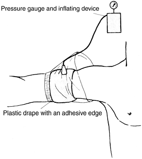 Figure 10-1. Application of a pneumatic tourniquet.
 -
Complications
of tourniquets include blisters and chemical burns (from “prep”
solutions that leak under the tourniquet) of the skin, swelling,
stiffness, and paralysis. Electromyographic changes have been
demonstrated following the use of a tourniquet even within the approved
time ranges.
-
-
The following is a summary of Occupational Safety and Health Administration (OSHA) regulation No. 1920, “Bloodborne Pathogens,” emphasizing staff and surgeon responsibilities.
-
Wash hands immediately after removing gloves.
-
Wash (with soap and water) any exposed skin (or flush mucous membranes) immediately (or as soon as feasible) after contact with blood or potentially infectious materials.
-
Do not bend, cut, recap, or remove needles or other sharps. If recapping is the only feasible method, then it must be done by using a mechanical device or the one-handed method.
-
Do not eat, drink, smoke, apply cosmetics or lip balm, or handle contact lenses in work areas where there is a reasonable likelihood of occupational exposure.
-
Perform all procedures involving blood or potentially infectious material to minimize spraying and splattering.
-
If outside contamination of transport containers is possible (or there is a potential for puncture), place potentially infectious material in a second container to prevent leakage during handling.
-
Use personal protective equipment
such as gloves, face shields, masks, gowns, shoe covers, and so on in
situations in which there is risk of exposure to blood or potentially
infectious material. -
Following an exposure, complete an incident report identifying the route of exposure and source individual.
A tube of the patient’s blood should be drawn, labeled “spin” and held
until the patient’s consent can be obtained. The employee health nurse
is to be contacted for testing as indicated. -
Hepatitis B virus (HBV) immunization is recommended for all employees
and is usually available by contacting the employee health nurse. The
authors believe that every surgeon is responsible for knowing his or
her own human immunodeficiency virus, hepatitis B, and hepatitis C
serologic status.
-
-
Prevention of surgical wound infections (16)
-
Operating room rituals are designed to decrease infection.
Despite the best designs, wound contamination and subsequent wound
infection continue. It is generally conceded that most wounds become
contaminated; however, usually only those with devitalized tissue,
large dead spaced with accumulating hematoma, or foreign bodies become
frankly infected. A study of the possible sources of coagulase-positive
staphylococci that contaminated surgical wounds during 50 operations
revealed that bacteria of bacteriophage types
P.158
that
were present only in the air were found in 68% of the wounds; 50% of
wounds contained bacteria of bacteriophage types that were found in the
patient’s nose, throat, or skin; 14% had bacteriophage types found in
the noses and throats of members of the scrubbed surgical team; and 6%
of the wounds had bacteriophage types found on the hands of the
scrubbed surgical team. Maximum contamination occurs early in the
operative procedure when there is a considerable amount of air
circulation caused by individuals moving about the room. After the air
quiets, the rate of contamination is less, but an increased exposure
time allows increased contamination. It is important to keep traffic in
the operating room to an absolute minimum, to walk slowly, and to avoid
fanning the air with quick opening of the doors, drapes, and towels. -
Studies show considerable variation in the filtration efficiency of different masks.
Cloth masks are only about 50% efficient in filtering bacterial
organisms and are rarely used. Numerous disposable masks have a
bacterial filtration efficiency greater than 94% according to the
manufacturers. Fiberglass-free masks are probably safer. Prolonged use
(averaging 4 1/2 hours of operation time) and the use of moist masks do
not impair ability to filter, except in the case of cloth masks. Since
the surgical masks work on a filtration principle, double masking can
actually increase the air contamination with bacteria because double
masking makes transportation of air through the mask pores more
difficult and forces more unfiltered air to escape along the sides of
the mask. -
Although airborne contamination is by far the most important source of contamination, skin contamination
does occur. Even with the use of 1% or 2% tincture of iodine, the
deeper areas of the epidermis are not bacteria free. With a 1%
concentration, no cases of skin irritation have occurred. If a higher
concentration is used, however, then the excess iodine should be
removed with alcohol after 30 seconds. One 5-minute scrub with
povidone-iodine is as effective as a 10-minute scrub in reducing
bacterial counts on the skin and keeping them down for as long as 8
hours. A 7.5% povidone-iodine (Betadine) skin disinfectant yields 0.75%
available iodine. More recent work shows that chlorhexidine gluconate (Hibiclens) may be the scrub detergent of choice for both the surgeon and the patient (17).
A comparative study between hexachlorophene (pHisoHex),
povidone-iodine, and chlorhexidine showed the latter to be probably the
most effective. There was a 99.9% reduction in resident bacterial flora
after a single 6-minute chlorhexidine scrub. The reduction of flora on
surgically gloved hands was maintained over the 6-hour test period. In
addition, the pharmacology of chlorhexidine is reportedly more
effective against gram-positive and gram-negative organisms, including Pseudomonas aeruginosa. -
Extremity draping.
Adhesive plastic drapes do not totally eliminate the patient’s skin as
a possible source of infection. Drape the extremities as described in App. E. -
Intraoperative procedures
to prevent postoperative wound infection include the elimination of any
large collection of blood. A hematoma is an excellent potential culture
medium. Wound suction is used whenever one anticipates continued
bleeding into the wound; however, their use in fracture, joint
replacement, and spine surgery has not been proven to decrease the
incidence of wound infection. Surgical wounds are carefully irrigated
to remove any potential contaminated residue before closing. In vitro
experiments using bacitracin 50,000 units plus polymyxin B sulfate
(Aerosporin) 50 mg in a liter of saline or lactated Ringer solution
have shown that 100% of Staphylococcus aureus, Escherichia coli, the Klebsiella organisms, and P. aeruginosa bacteria were killed by a 1-minute exposure to the antibiotic solution (18). Staphylococcus epidermidis organisms were also killed. Only the Proteus organisms showed significant resistance to this antibiotic irrigation (only 3%–22% were killed). Proteus
organisms are uncommon as a cause of immediate postoperative infections
in musculoskeletal surgery, however, when the wounds are not previously
contaminated or
P.159
infected.
Data indicate that irrigation of surgical wounds with a solution
containing bacitracin and polymyxin B sulfate or bacitracin and
neomycin could potentially lower the incidence of postoperative
infections (19).
A large number of patients are sensitive to neomycin, so its use is
generally discouraged. Polymyxin B is sometimes difficult to obtain
from the manufacturer. In this situation, some surgeons use a dilute
Betadine solution as a topical antibiotic irrigant; however, this
solution is toxic to tissue. Data confirming that antibiotic irrigants
are superior to sterile saline in preventing surgical wound infection
are generally lacking in orthopaedic surgery. Splash basins are a
source of bacterial contamination and should not be used. -
The incidence of infection increases in wounds open for longer than 2 hours.
Whether this is a result of the increased exposure to the air, failure
of masks, skin contaminants, or more trauma in the wound is not
certain. Even with lengthy surgical cases, with good surgical technique
the rate of deep wound infection on “clean” orthopaedic cases should
not exceed 1%. -
Laminar air flow systems
appear to be an effective means of reducing postoperative infection
rates as long as the flow of air is kept laminar or streamlined across
the operative area (e.g., during hip surgeries). These systems are not
effective if the air becomes turbulent across the operative area
because, for example, of the position of people in the operating room
(e.g., during knee replacement surgery) (20). -
Hooded surgical exhaust systems
are effective but cumbersome and costly. They are often used to protect
the operating team from infection by high-risk patients. -
Whenever a subsequent surgical wound infection occurs in a clean, uneventful surgical case, consider a nasal culture from all those present at the time of the operation.
-
-
Malignant hyperthermia
-
Pathophysiology.
The target organ in malignant hyperthermia is skeletal muscle. Certain
triggering events, such as the administration of halothane or
succinylcholine, precipitate release of calcium from the
calcium-storing membrane (sarcoplasmic reticulum) of the muscle cell.
The abnormal transport of calcium results in recurrent sarcomeric
contractions and consequent muscle rigidity. The metabolic rate is
accelerated, causing heat and increased carbon dioxide production with
accelerated oxygen consumption. Core body temperature increases. -
History. The
potentially fatal syndrome is an autosomal dominant metabolic disease.
In 40% of reported cases, an orthopaedist is the first to encounter
this disorder. The incidence in the United States is approximately
1:1,000. The syndrome is associated more frequently with patients
having congenital and musculoskeletal abnormalities: kyphosis,
scoliosis, hernia, recurrent joint dislocations, club foot, ptosis, or
strabismus. Malignant hyperthermia can occur at any age but is most
likely to occur in a young individual with a large muscle mass. After
exposure to an anesthetic (or other stress), body temperature rapidly
increases. -
Examination.
A rapid elevation in body temperature is noted early. Cardiac
arrhythmias usually are concurrent, can progress to ventricular
tachycardia, and may end in ventricular fibrillation with subsequent
death. The soda lime canister may turn blue and become palpably hot.
Tetanic muscle contractions occur in approximately 60% of cases. Like
so many conditions in orthopaedics, early recognition is crucial.
Temperature and electrocardiographic monitoring during surgery is
mandatory. A rapid temperature elevation (even from an initial
subnormal temperature), tachycardia, hypertonia of skeletal muscle,
unexplained hyperventilation, overheated soda lime canister, dark
blood, sweating, and blotchy cyanosis are all indicative of possible
malignant hyperthermia. -
Treatment
-
Prevention
-
Obtain a careful past history and family history,
inquiring especially about fatal or near-fatal experiences following
emotional, physical, traumatic, or surgical stress or about a relative
who died of an obscure cause in the perioperative period. -
Administer prophylactic dantrolene (Dantrium) orally
in doses of 2.2 mg/kg body weight (range of 2–4 mg/kg body weight) at
12 and 4 hours before the induction of anesthesia when the history is
positive. -
Avoid the use of halothane (Fluothane) and succinylcholine (Anectine) in high-risk patients.
-
-
Management of an evolving malignant hyperthermia syndrome
-
Immediately discontinue all anesthetic agents and muscle relaxants and terminate the surgical procedure as quickly as possible.
-
Hyperventilate with oxygen.
-
Use IV sodium bicarbonate, 4 mL/kg body weight, and repeat as necessary until blood gases approach normal.
-
Administer mannitol, 1 g/kg body weight and furosemide (Lasix), 1 mg/kg body weight, which help maintain urine output to clear myoglobin and excessive sodium.
-
Treat hyperkalemia with approximately 50 mg of IV glucose with 50 units of insulin.
-
Control arrhythmias with procainamide (Pronestyl).
-
Cool the patient
with immersion in ice water and expose to an electric fan to facilitate
evaporation. Refrigerated saline or Ringer’s lactate administered
intravenously is helpful. Maintain cooling procedures until the body
temperature is less than 38°C. -
Dantrolene (approximately 12 mg/kg body weight) used intravenously is one of the mainstays of treatment and probably works by reducing calcium outflow from the sarcoplasmic reticulum into the myoplasm.
-
Physiologic monitoring
by electrocardiography and measurement of the central venous pressure,
blood gases every 10 minutes, volume and quality of renal output, serum
electrolytes, glucose, serum glutamic oxaloacetic transaminase (SGOT),
creatine phosphokinase (CPK), and blood urea nitrogen (BUN) is
important. -
Good prognostic signs
are lightening of the coma (often heralded by restlessness), return of
reflexes, return to normal temperature, reduced heart rate, improved
renal output, and return of consciousness.
-
-
-
Complications
-
Weakness and easy fatigability persist for several months.
-
Death owing
to ventricular fibrillation can occur within 1 or 2 hours from the
onset of the condition. If death occurs later, then it is usually a
result of pulmonary edema, coagulopathy, or massive electrolyte and
acid-base imbalance. If the patient dies after several days in a coma,
then the cause is usually renal failure or brain damage.
-
P.160 -
-
-
Introduction.
Much of the remaining discussion is modified from a psychomotor skills
course originally organized for the University of Washington Department
of Orthopaedic Surgery residents by F. G. Lippert III, M.D., in the
1980s. -
Techniques for checking the function of grasping type surgical instruments (21).
The breakdown of high-quality instruments is often the direct result of
their misuse. Forceps, hemostats, needle holders, and clamps frequently
are misused in orthopaedic surgery. They can be misapplied to various
pins, nails, screws, and
P.161
plates when pliers are not readily available. They are also misused to clamp large sponges, tubing, and needles.-
It is annoying to a surgeon and hazardous to the patient when forceps or a hemostat springs open. This mishap is caused by forceps malalignment, worn ratchet teeth, or lack of tension at the shanks.
-
Start the equipment check by visually checking jaw alignment
by closing the jaws of the forceps lightly. If the jaws overlap, they
are out of alignment. Then, determine whether the teeth are meshing
properly on forceps with serrated jaws. In addition, try to wiggle the
instrument with the forceps open and holding one shank in each hand. If
the box has considerable play or is very loose, then the jaws are
usually malaligned and the forceps need repair. -
To check the ratchet teeth
on instruments, clamp the forceps to the first tooth only. A resounding
snap should be produced. Then hold the instrument by the box lock and
tap the ratchet teeth portion of the instrument lightly against a solid
object. If the instrument springs open, then it is faulty and needs
repair. -
Test the tension between the shanks
by closing the jaws of the forceps lightly until they barely touch. At
this point there should be clearance of 1/16 or 1/8 inch between the
ratchet teeth on each shank.
-
-
To test the function of the needle holder,
first clamp the needle in the jaws of the holder, then lock the
instrument on the second ratchet tooth. If the needle can be turned
easily by hand, then set aside the instrument for repair. When the
instrument is new, it holds a needle securely on the first ratchet
tooth for a considerable time. Needle holders such as a Crile, Wood,
Derf, or Halsey, used in plastic surgery, should hold at least a 6-0
suture. Needle holders such as Castroviejo or Kalt should hold a 7-0
suture.
-
-
Surgical exposure instruments. There are various methods for testing the efficiency of surgical scissors.
The Mayo and Metzenbaum dissecting scissors should cut four layers of
gauze with the tips of their blades. Smaller scissors (less than 4 in.
long) should be able to cut two layers of gauze at the tips. All
scissors should have a fine, smooth feel and require only minimum
pressure by the blades to cut properly. The scissors action should not
be too loose or too tight. Check the tips of the scissors for burrs or
for excessive sharpness. Closed tips of the scissors should not be
separated or loose. The precise setting of the blade is very important.
Sharpening surgical scissors is a skilled procedure, usually requiring
an exceptional craftsman to properly grind and set the blades.-
Periosteal elevators
-
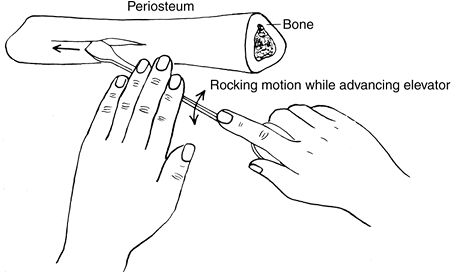
Periosteal elevators are instruments designed to strip (or elevate) periosteum from bone.
As the instrument is pushed along the surface of the bone, the soft
tissue is lifted from the underlying bone. Periosteal elevators are
thus instruments for blunt dissection and are designed to follow bony
surfaces without gouging into the bone or wandering off into the soft
tissues. They are also useful in blunt separation of other tissue
planes such as in the exposure of the hip joint capsule. The use of
periosteal elevators is most satisfactory in areas where tissue planes
are not too firmly adherent. At bony attachments of a ligament or
capsule, collagen fibers plunge deeply into the bone so that the
elevator does not slide within a tissue interspace; sharp dissection
with a scalpel is more appropriate here. In fracture fixation,
periosteal stripping, which can adversely affect blood supply and bone
healing, should be minimized where ever possible. -
Elevators are made in different sizes and shapes.
They may be narrow or wide. Sharp corners allow insertion of the
instrument into a tissue plane or beneath the periosteum. On the other
hand, most blade corners are rounded to avoid producing damage when
pressure is applied to the central portion of the blade. -
The technique
of making a periosteal incision with a scalpel before the elevator is
used helps form well-defined edges. When periosteum is being
P.162
elevated
from bone, the first rule of safety is to always keep the blade against
bone. If the instrument is allowed to slip off into the soft tissues,
then vessels and nerves can be damaged. It is important to use two
hands whenever possible to have a stable grasp on the instrument and to
maintain fine control. A gentle rocking motion while advancing the
blade produces more even results (Fig. 10-2).
Although periosteal elevators need not be honed to the same sharp edge
required for bone-cutting osteotomes, they do require some
tissue-penetrating ability to be most effective. Nevertheless, they
should not be so sharp as to incise soft tissue instead of stripping it. -
Important guidelines for tool selection and usage
-
Select the correct size. Generally, use a small elevator for small bones and a large elevator for large bones.
-
Select the correct shape. Usually, a sharp elevator is used to elevate periosteum and a rounded elevator to dissect soft tissue.
-
The periosteum is incised with a scalpel.
-
The corner of the elevator is used to reflect a periosteal edge.
-
The periosteum is elevated evenly without tearing.
-
The elevator is kept on the bone.
-
The bone is not engaged by the elevator.
-
A rocking motion is used while advancing the elevator.
-
Two hands are used, one for power and one for stability and dissecting.
-
Overpenetration into the soft tissues by the elevator should be avoided.
-
A gentle technique must be used.
-
-
-
-
Bone cutting instruments: osteotomes, gouges, and mallets
-
The major difference
between an osteotome and a chisel is that an osteotome bevels on both
sides to a point, whereas the chisel has a bevel on only one side (Fig. 10-3). The term osteotome is made up of osteo, which means “bone,” and tome,
which means “to cut;” the purpose of the tool is to cut bone. The cut
should be produced under excellent control; otherwise, the bone can be
split. Osteotomes come in different shapes and sizes. There are
different types of handles that make for differences in holding and
striking surface capabilities.![]() Figure 10-2. Proper use of a sharp-edged periosteal elevator. (From G. Spolek, unpublished data, 1974, with permission.)
Figure 10-2. Proper use of a sharp-edged periosteal elevator. (From G. Spolek, unpublished data, 1974, with permission.)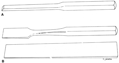 Figure 10-3. Differences between an osteotome and a chisel. A: A chisel. B: Two types of osteotome.
 -
Selection of instruments
-
Chisels are
used to remove bone from around screws and plates instead of osteotomes
because they can be easily sharpened when the edges are nicked from
being hit against the metal. It is better to keep a set of chisels
specifically for removing metal implants. -
Osteotomes
are used to cut bone and to shave off osteoperiosteal grafts. In fusion
procedures, they are used to remove the cartilage and subchondral bone
as well as to perform “fish scaling” of the surface of bone for bone
graft union. -
Gouges are
used to provide strips of cancellous bone graft from the iliac crest.
They are also used to clean out the cartilage and subchondral bone from
concave joint surfaces. -
Mallets are used to produce power to drive the aforementioned tools through bone and cartilage.
-
-
Proper technique
-
The dominant hand is used to grasp the mallet, which strikes the back of the instrument and drives it through bone. While hitting the osteotome through bone of increasing density,
notice that the sound becomes high pitched and the osteotome moves a
shorter distance with each blow. In addition, there is a tightening or
holding quality about the osteotome so that it moves less freely. This
tightness is an indication that bone is coming under more tension and
that a split of the bone is about to occur. Decrease the tension by
working the osteotome back and forth through the bone. Occasionally, it
is necessary to remove the osteotome to take a different direction or a
slightly different angle. It is frequently important to prescore the
bone so that the cutting goes directly toward it instead of splitting
the bone in an unwanted area. -
Precautions
include preventing the osteotome from sliding off the bone or from
cutting through the bone rapidly and then plunging into soft tissue.
The nondominant hand merely supports and directs the osteotome against
bone until it gets started but does not apply any major pressure on the
tool. Starting the cut is best accomplished by placing the osteotome at
right angles to the bone, then angling the tool only after the initial
score and cut have begun. These precautions protect both the patient
and the hands of the assistant.
-
-
Specific maintenance is necessary in the handling and sharpening of the tools. The sharpening of an osteotome or a gouge is a difficult and critical
P.164
procedure that must be undertaken with great caution. If the tool is
overheated during sharpening, then the temper is lost. The loss can be
recognized by the bluish-gray color of the metal in contrast to the
silvery color usually associated with stainless steel. In addition,
care must be taken in cleaning and handling the tools while they are on
a surgical table so that the ends do not become damaged by other
instruments. Keep them in a rack during the sterilization process, not
in a basin with other tools.
P.163 -
-
Bone saws and files.
In general, the operator must control the amplitude, direction, and
length of force applied to the saw. The use of lactated Ringer (or
saline) irrigation to disperse heat is always recommended.-
The proper use of Gigli saw
includes making a scribe mark at the start of the technique if
possible. The surgeon must be careful not to drop or tangle the saw
cable, to keep the cable at approximately 90 degrees, and to use the
middle two thirds of the saw while applying a constant, steady tension.
Excess body movement should be avoided to produce a straight bone cut.
The use of saline coolant is recommended. -
A bone file
or rasp is usually used to round the edge of a bone cut. Both hands
should be used to control the direction of the tool and only a forward
force should be applied.
-
-
General bone screw biomechanics
-
Holes are
generally drilled in bone for the purpose of inserting screws to hold
orthopaedic implants. Careful, even compulsive, attention to detail in
selecting equipment and in drilling holes properly is vital to the
performance of an implanted fixation device. The interlocking threads
of screw and bone overlap by less than 0.02 inch. Any failure of
equipment or technique that decreases this margin drastically reduces
the holding power of the screw. Given the severe loading environment in
which most orthopaedic implants operate, the holding power of a screw
is an important matter. Force concentrations that occur when a screw
fails to hold properly can result in a rapid failure of the implant. -
Drill bits (1)
-
Common defects in equipment.
Since hole drilling is frequently taken for granted (the major
attention being paid to the implant itself), drill bits come to the
operating room in various stages of disrepair.-
A dull point
is one of the most serious and least noticed defects. When the point is
sharp, virtually all heat generated in drilling is carried away in the
bone chips that are formed. Even slight dullness drastically increases
friction between the point and the bone. This friction causes excessive
heating and can affect the strength of the bone around the hole as well
as cause inefficient cutting, which results in an oversized hole. -
The flutes should be examined for nicks and gouges
that score the walls of the hole, causing excessive heating and
oversized holes; if identified, the drill bit should be discarded. -
A drill with a scored shank does not sit straight in the chuck and causes the same trouble as a drill sharpened off center.
-
Drill bits of the wrong size
are sometimes selected. A difference of just 1/100th of an inch is
enough to diminish the holding power of a screw severely, even though
insertion of the screw appears normal. -
A bent drill bit
causes the same difficulty as a drill bit sharpened off center. One
cannot tell whether a drill bit is bent by simply looking at it; it
must be rotated in the fingers. Even small bends create holes that are irregular, and the drill bit is very susceptible to breakage.
-
-
Technique
-
Prevent the drill point from wandering off center.
-
Thin surgical drill bits are flexible, and if the drill is inadvertently held slightly off perpendicular when starting the hole, the point may bend the opposite way, making the point wander.
-
If the drill bit is not positioned properly in the chuck
or if debris is present in the chuck or on the shank, then the drill
bit may wander off center. Another error involves insertion of the
drill bit too deeply into the chuck, which causes damage to the flutes
when the drill is tightened. Check the drill for these problems before
proceeding.
-
Tighten the chuck down. If the chuck is loose, then it can rotate relative to the drill and score the shank.
-
Too little force
(not too much force) is a common defect in technique. Push hard enough
to cause a constant progression of the drill bit; otherwise, too much
energy is being dissipated as friction rather than as cutting, causing
excessive heating. -
Avoid overpenetration.
Slow the drill motor when the drill bit tip begins penetrating (noted
by a change in resistance) and finish with care. With care, the surgeon
will note that the pitch of the sound made by the drill drops just
before penetration of the cortex. The tip should not penetrate more
than one eighth of an inch through the opposite cortex. -
When the drill bit breaks through the opposite cortex, keep it rotating in the same direction as you back it out. The chips are thus carried out with the drill bit instead of being left in the hole.
-
Drill motors should be lubricated frequently.
Special surgical lubricants are available. Do not use mineral oil or
ordinary oil because they are not permeable by steam and can harbor
bacteria and spores even after autoclaving. -
Battery packs for power equipment should be kept charged with backups available.
-
-
Adhere to the following points when using drills:
-
Choose the correct drill bit. Reject dull, scored, bent, oversized, and incorrectly pointed drill bits. In general, use new drill bits for each case.
-
Insert the drill bit correctly in the chuck
with the drill bit centered and the chuck tightened on the shank only.
Use quick release systems whenever possible to avoid potential problems. -
Tighten the chuck sufficiently.
-
Start the drill hole perpendicular to the surface; then change to the desired direction.
-
Maintain adequate pressure on the drill to promote cutting and lessen heat production.
-
Maintain the proper direction of the hole and penetrate the far cortical wall carefully, with the drill bit minimally penetrating.
-
Keep the drill rotating while backing it out in order to clear the hole of bone chips.
-
-
-
Screws (1)
-
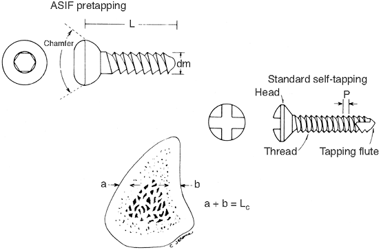
Cortical bone screws
are fully threaded and come in a variety of sizes for different sized
bones. Non–self-tapping screws require a tap to cut the threads into
the bone before insertion (Fig. 10-4). -
Cancellous bone screws
have a thinner core diameter plus wider and deeper threads to better
grip the “spongy” bone. They are fully or partially threaded. Tapping
is required only through the cortical surface. -
Lag screw fixation
can be achieved with either a partially threaded cancellous screw or by
drilling a “gliding hole” (of the same size as the outer thread
diameter) for the near cortex, allowing a cortical screw to produce lag
compression. -
Large, medium and small cannulated cancellous bone screws are designed to pass over a guidewire. With this type of system the surgeon can
P.166
place a guidewire exactly where desired so that the cannulated drill,
tap, and screw passes over this wire for precise placement.![]() Figure 10-4. Comparison between Association for the Study of Internal Fixation (ASIF) and standard cortical bone screws.
Figure 10-4. Comparison between Association for the Study of Internal Fixation (ASIF) and standard cortical bone screws. -
Length of screw.
Drilling the proper hole is only the first step in firmly fixing the
screw into the bone. The second part is selecting a screw that is of
adequate length (22).-
To use a depth gauge
properly, do not insert the gauge any farther than necessary. Be sure
to have hooked the far end of the hole and not an intermediate point.
Consider allowing additional length (usually 2 mm) over the scale
reading on the depth gauge when choosing the screw length. -
A self-tapping screw has a tapered point whose holding power is further reduced by the flutes cut for tapping purposes. The distal
2 mm of the self-tapping screw has no holding power at all, and the
next 2 mm has very little. Screw lengths are measured from the proximal
edge of the chamfered head to the distal point of the screw (Fig. 10-4).
If a screw is installed in a plate, then additional length must be
allowed. Given the fact that bone screws hold principally in cortical
bone, a screw that is short by 4 mm may lose 50% of its holding power. -
When a screw is inserted on a subcutaneous border of bone, the hole should be countersunk before the depth is measured and the screw inserted.
-
Tighten the screw snugly and no more,
so as not to strip the threads of the bone when inserting the screw.
Retighten cortical screws three times to allow for the obligate loss of
strain between screw and bone resulting from loss of fluid in the bone
and stress relaxation.
-
-
-
-
General principles of plating
are described in the following paragraphs and generally follow the
concepts and techniques advocated by the Association for the Study of
Internal Fixation (AO/ASIF) group, which supplies the most widely used
fracture fixation implants in use. The plates are listed by their
general biomechanical functions (11).-
Protection or neutralization plates are used in combination with lag or other screws and protect the screw fixation in diaphyseal fractures. Without the
P.167
plates, the screw fixation by itself does not withstand much loading
and does not allow for early range of motion. The lag screws provide
for most of the interfragmental compression and the plate protects the
screws from torsion, bending, and shearing forces (Fig. 10-5).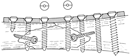 Figure 10-5.
Application of a conventional or neutralization internal fixation
plate. The neutral drill guide is used. Neutralization plate allows for
more loading of the fracture than simple lag screw fixation. -
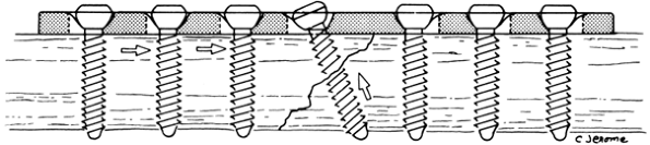
The dynamic compression plate (DCP)
brings compression to the fracture site by its design. Recently,
low-contact dynamic compression plates (LCDCPs) and point contact
plates (PCPs) have been developed that allow greater freedom in screw
insertion through the plate and also limit the pressure necrosis effect
of the plate on the cortical bone surface (1) (Figs. 10-6, 10-7, 10-8).![]() Figure 10-6.
Figure 10-6.
A longitudinal section of the dynamic compression plate (DCP) screw
hole. Insertion of the Association for the Study of Internal Fixation
(AO/ASIF) screw causes self-compression of the fracture site by the
plate by sliding down an inclined cylinder to a horizontal one. (From
Mueller ME, et al. Manual of internal fixation, 2nd ed. Berlin: Springer-Verlag, 1979:71, with permission.)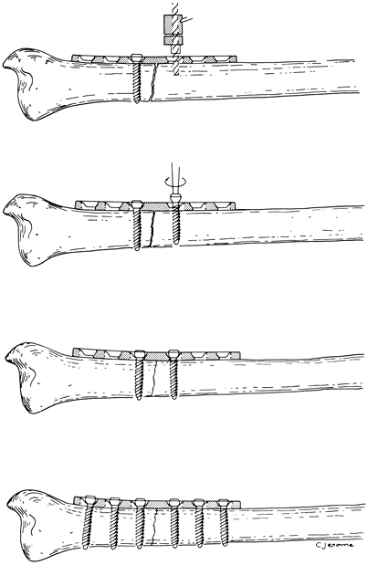 Figure 10-7.
Application of self-compression plate. The load drill guide is used for
placement of the second drill as shown in the top illustration. The
other holes are drilled with the neutral drill guide. (From Mueller ME,
et al. Manual of internal fixation, 2nd ed. Berlin: Springer-Verlag, 1979: 67,75.)![]() Figure 10-8.
Figure 10-8.
Dynamic compression plate with lag screw. The compression through the
plate is applied first; then the lag screw is added to prevent a shear
force on the lag screw. -
By their nature, many epiphyseal and
metaphyseal fractures are subject to compression and shearing forces.
Lag screws are used to reconstruct the normal anatomy, but they cannot
overcome the forces of shear and bending because of the thin cortical
shells in these areas, especially in comminuted fractures. The fixation
is supplemented with supporting or buttress plates to prevent
subsequent fracture displacement from shear or bending stresses.
Specially designed buttress plates include the T plate, the T buttress plate,
the L buttress plate, the lateral tibial head plate, the spoon plate,
the cloverleaf plate, and the condylar buttress plate. Additional
plates for special locations (e.g., proximal and distal tibia,
calcaneous) have recently been marketed. -
To restore the load-bearing capacity of
an eccentrically loaded fractured bone and minimize the forces borne by
the fixation device, it is necessary to absorb the tensile forces (the
result of a bending movement) and convert them into compressive forces.
This requires tension band fixation, which
exerts a force equal in magnitude but opposite in direction to the
bending force (assuming the bone is able to withstand compression) (1). Therefore, comminuted fractures should be treated with other fixation devices or protected longer from bending moments.-
Ideally, tension band plating techniques are used on the femur, humerus, radius, and ulna (1).
-
Tension band wire internal fixation
-
The purpose
of tension band wire internal fixation is to secure the fragments of
fractures in such a way that the application of normal forces (muscle
forces, loads generated by walking) produces a compression of the
fragments at the fracture site instead of pulling the fragments apart.
The advantage of this technique is that the fixation is secure enough
to allow early (if not immediate) use of the limb. Indications for
tension band wiring are generally in the treatment of avulsion
fractures at the insertion of muscles, tendons, or ligaments. If one
has to deal with a rotational component or when accurate reduction of
the fragments is vital, then introduce two parallel Kirschner wires
before the insertion of the tension band. The tension band then is
passed around the wire ends. -
The tension band principle
works only when there are applied natural forces that tend to bend the
bone at the fracture site. The olecranon, patella, and tip of the
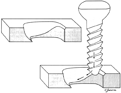
fibula are examples of such sites. Fig. 10-9 describes the principles of tension band wire internal fixation for the treatment of a transverse fracture of the olecranon. -
As shown on Fig. 10-9, a single-screw fixation without a tension wire loop is not adequate because the screw bends with triceps activity and only half the fracture site is placed in compression.
-
It is evident that the wire is pulled in
tension by the bending effect of the muscle force. Therefore, whatever
force is exerted across the bony interface must be compressive and equal in magnitude to the force carried by the wire.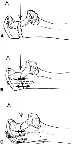 Figure 10-9.
The principles of tension band wire internal fixation as applied to a
transverse fracture of the olecranon. Forces on an intact olecranon
cause a bending moment. A: Same forces on a transverse fracture of the olecranon cause the fracture to open. B: Screw fixation provides only partial compression of fracture. C: Fixation of the cortex under tension creates equal compressive forces across the fracture site. -
Note that the tension band wiring does not provide the desired rigidity for loading from all directions. It is intended to resist only the strong tension forces applied through the action of specific muscles or through loading.
-
The application of tension band wire fixation is discussed in the treatment of olecranon fractures in Chap. 18, III.B and of patellar fractures in Chap. 24, III.A.3.
P.170 -
-
-
Numerous other plates and screws
serve the aforementioned functions with various shapes and sizes to
adapt to the local anatomy. They include straight and offset condylar
blade plates, reconstruction plates (more easily contoured in all three
planes, which make them optimum for use in the pelvis and distal
humerus), dynamic hip screws, dynamic condylar screws, and specialized
locking plates where the screw head is threaded into the plate. These
are especially useful in osteoporotic bone. -
Contouring internal fixation plates.
Internal fixation plates may be contoured to fit the bone before
application. Such contouring increases the bone-plate interface area so
that the loads normally carried by the bone can be transferred to the
plate by friction rather than pure shearing on the bone screws. To
contour a plate template, press the aluminum template of the proper
length against the bone, then bend the plate to match. Plate benders
may be handheld singular, handheld pliers, and table-mounted bending
presses. Locking plates in general should not be contoured, as the hole
configuration will be distorted.-
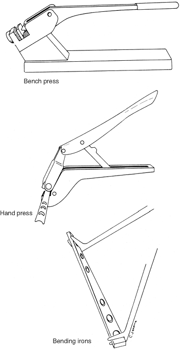
The bending press
gets the most use because most contouring is two-dimensional. The anvil
is adjustable so that the handle can be used in the position with the
best control (near the end of its travel). The hand press
P.171
is used mainly for small plates, for plates with a semitubular cross
section, and reconstruction picks. There are three different anvils
(straight, convex, and concave) to prevent squashing of the semitubular
plates. The bending irons
are for applying twists and are most conveniently used when the jaws
are opened upward to prevent the plate from falling out and when the
handles are on the same side of the plate. Theoretically, uniform twist
occurs between the irons, so start with them at the ends of the desired
twist length. Once the twist is started, move the irons closer together
to get localized contours. DCPs are weakest through the holes, where
most of the twist occurs, so try to position the irons to prevent
excessive bends at any one hole. Use the press first because the plate
does not fit the anvil if the bending irons are used to twist
beforehand. LCDCPs have more uniform characteristics and do not bend at
the holes. Fig. 10-10 illustrates the three types of instruments. -
Important guidelines in usage
-
Bend the plate to form a smooth, continuous contour.
Because the press causes a single, rather abrupt bend directly beneath
the plunger, a long continuous curve is best formed by several small
bends rather than a few sharp bends. -
Avoid bends through screw holes
because they alter the shape of the countersunk surface of the hole so
that the screw does not seat properly. If a bend must be made through a
screw hole, go easy on the press handle because the plate is weaker at
a hole and less force is required to bend it. -
If the required contour contains a series of shallow and sharp bends, do the shallow ones (greatest radius of curvature) first and progressively work toward the sharper bends, as shown in Fig. 10-11.
This procedure tends to produce smooth contours and allows easier
template matching. Contouring to fit a bump or knoll on the bone
surface requires three bends: two convex and one concave. -
Do not overbend but ease into a contour (see Fig. 10-11).
Overbending requires straightening, which, besides being time-consuming
work, hardens the plate in that area and thus reduces the strength of
the plate. -
When contouring the plate, do not match
the template exactly, but rather alter (underbend or overbend) the
shape so that there is a 1- to 2-mm clearance between the plate and the bone at the site of a transverse fracture. This technique causes compression of the cortex opposite the plate when the screws are tightened. -
Minimize scratching or marking of the plate surface.
If the surface is scratched, then a potential corrosion site is
created. Therefore, use the proper bending irons with smooth jaws
rather than vise grips.
-
-
P.168P.169 -
-
Cerclage is a
technique of encircling a fractured bone with Parham-Martin band,
stainless steel or titanium wire, Dahl-Miles cable, or other
nonabsorbable material to hold the fracture in reduction in conjunction
with stronger, more permanent fixation. Cerclage is not recommended as
a primary method of internal fixation of fractures. There are many
techniques for applying cerclage wire.-
General rules of wire cerclage
-
Avoid putting kinks in the wire.
Kinking is easy, particularly if the wire is coiled. Kinks result in
stress concentrations that drastically reduce the fatigue strength of
the wire. -
Be sure the loop around the bone is perpendicular to the long axis of the bone. Otherwise, the loop may appear tight, but any slight movement causes it to shift and loosen.
-
Use the cerclage wire only to hold the
fracture site in reduction, not to apply compression. The wire is not
strong enough to apply useful compression.
P.172
Tighten the wire only until it is snug; be careful not to overtighten while making the knot.![]() Figure 10-10. Plate benders.
Figure 10-10. Plate benders. -
Use the proper-sized wire;
18-gauge is common and has sufficient strength. The area of the wire is
a measure of its load-carrying capacity, which depends on the square of
the diameter. Thus, the load-carrying capacity decreases considerably
with even moderate decreases in radius.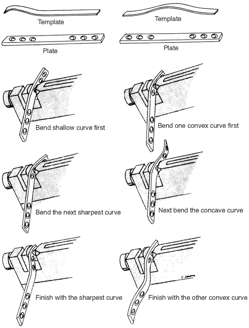 Figure 10-11. Steps in plate contouring.
-
-
Wire tighteners
-
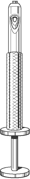
The Bowen wire tightener is an excellent tightener (Fig. 10-12).
Both wires are passed into the nose of the appliance and out the side.
The outer wheel is turned to secure the wire against the inside
cylinder. By turning the inside wheel, the inside cylinder is pulled up
the handle of the device, effectively tightening the wire to the
desired tension. The whole instrument is rotated to twist the wire, and
the wires are then easily cut just distal to the last twist. -
The Kirschner wire traction bows (see Fig. 9-1) have a mechanical advantage that varies with the jaw opening. The lowest mechanical advantage
P.174
is in the fully closed position; this increases gradually with
increasing jaw width. The average mechanical advantage for both the
large and small bows is 30:1. The last one fourth inch of jaw opening
coincides with a sudden increase in mechanical advantage of greater
than 400:1, but this last one fourth inch rarely is used.![]() Figure 10-12. The Bowen wire tightener.
Figure 10-12. The Bowen wire tightener. -
Comparison of knot strength. The types of knots described here were tied in 20-gauge steel wire and pulled apart in a tension test machine:
-
Type of knot/maximum force before failure
-
ASIF loop/15.8 lb
-
Twist (one turn)/23.2 lb
-
Twist (three turns)/24.2 lb
-
Square knot/59.0 lb
-
-
These results are preliminary, but they
do afford some conclusions. An ASIF 1oop is the weakest and is heavily
dependent on careful knot formation for its strength. The twist is 47%
stronger, but additional turns beyond the first 360-degree turn do not
significantly increase the strength of the knot. The reason for using
several twists is to provide some residual resistance after untwisting
begins, although whether this resistance actually occurs has not been
determined. The square knot is the strongest of all. Failure occurs by
wire fracture just below the knot.
-
-
P.173 -
-
Principles of intramedullary nailing
-
An intramedullary nail allows for internal splinting with a fixation device in the medullary canal. The possibility
of gliding along the dynamically locked nail promotes compression
forces at the fracture site, and the stability from the long working
length of the nail provides stiffness. -
This necessary reaming of the canal and
resulting disruption of the endosteal blood supply in a severely open
fracture that already has disruption of the
P.175
periosteal blood supply may increase the chance for a nonunion or infection. In these situations, the use of a smaller unreamed nail
seems to provide satisfactory results. Because these smaller unreamed
nails have less mechanical stability, they generally require
interlocking (placing one or two screws across the cortex and nail
superiorly and inferiorly) (1). The incidence of implant failure by fatigue fracture is much greater than the larger diameter implants inserted with reaming. -
In addition to the aforementioned indications, the treatment of complex fractures requires an interlocking nail
to prevent excessive shortening and rotation. It is recommended to
always statically lock the nail to avoid malrotation and shortening,
which can occur related to unrecognized minimally displaced cracks.
-
-
External skeletal fixation
-
The use of external fixation, particularly in the treatment of comminuted or open fractures, has regained popularity. Lambotte (1902) is generally given credit for the first use of external pin fixation. Anderson (1934), Stader (1937), and Hoffman (1938)
all popularized a technique of external skeletal fixation. Vidal and
Adrey, using the Hoffman approach, further refined the technique. Most
recently, Ilizarov developed and popularized the ring fixator with
small wire transfixion for use in limb lengthening, bone transport, and
fracture fixation. -
Multiple external fixators are currently on the market. Regardless of which technique is used, certain basic principles must be followed.
-
The
insertion of the pins and the attachment of the external skeletal
fixation is a major procedure performed in the operating room following all normal operating room procedures. -
The skin and fascia must be incised so that there is no shear stress on these structures that could result in necrosis.
-
The pins must be inserted slowly with a hand chuck after predrilling with a saline-cooled drill bit to avoid heat necrosis of bone.
-
There must be a minimum of two pins above and two pins below the fracture.
Three pins add a small amount of stability in some systems. Maximal
fracture stability is achieved by using half pins separately within
each bone segment and by placing the connecting bar as close to the
skin as possible. Additional stability is attained by stacking a second
bar (this must be done by planning ahead because parallel pins are
required in some systems) or using a second row of pins and connecting
bar. -
Terminally threaded half pins are used to prevent loosening and sliding of the unit in the bone.
-
Avoid motion of skin and fascia against the pins.
-
Use strict aseptic techniques when dressing the pin sites.
-
Avoid distraction. Make adjustments to ensure coaptation or impaction of the fracture fragments during the course of healing.
-
Studies have clearly shown that external fixation devices can be used to treat fractures to union.
It was previously thought that the devices should be removed as soon as
fractures are stabilized and be replaced by casts or cast-braces, if
necessary, to allow weight bearing across the fracture to stimulate
healing. -
External pin fixation is a complex procedure that requires skill and attention to detail.
-
-
Possible indications
for external skeletal fixation include the comminuted Colles’ fracture
and comminuted or open fractures of the tibia, particularly in the
proximal and distal ends where intramedullary nailing is not feasible
and the risk of infection from the more extensive soft-tissue stripping
required for plating is significant. The apparatus should be used with
caution for fractures in the humerus, femur, and pelvis because of the
higher incidence of pin tract infection and pin loosening. Patient
acceptance is also higher with other devices. The thin wire fixator
technique developed by
P.176
Ilizarov
has made application in the metaphyseal region more secure, but because
of the use of these “through” pins, the anatomic knowledge required in
inserting them is greater. The Ilizarov frames are useful for fracture
management, bone transport, and limb lengthening.
-
-
Obtaining bone graft material
is a common procedure in orthopaedics. On most occasions, the iliac
crest is used for the graft, although various bone grafts are
available. After closure of the wound, installation of 0.5% bupivacaine
without epinephrine reduces the postoperative pain. The following is
the recommended surgical technique:-
For removal of a small amount of bone,
tension the skin over the iliac bone and cut to the ilium without
entering muscle or fascial planes. A small periosteal flap is excised
with sharp dissection from the superior aspect of the crest. A window
then is cut through the cortical bone between the inner and outer
tables. The periosteum is not stripped from the bone so pain is less. -
For removal of sizable grafts,
the surgeon must decide whether to use the anterior or posterior part
of the iliac crest. Often, the choice is dictated by the position of
the patient during operation. Anticipating the possible need for iliac
bone grafting for proper positioning, prepping, and draping is required
for the smooth flow of the operation. Whenever possible, the patient
should be positioned so that the area of the posterior superior iliac
spine can be used.-
Removal of bone from the anterior part of the iliac crest.
The skin incision must be long enough to allow a comfortable exposure
of the anterior 4 to 5 in. of the iliac crest. Sharp dissection is used
to expose the crest. A periosteal elevator is used to expose the inner
or outer surface of the ilium. The bone may then be removed by an
osteotome or gouge. Care should be taken not to involve both tables of
the ilium to minimize hematoma formation and postoperative pain and
deformity. One should also be careful to avoid the anterior superior
spine for reasons of cosmesis as well as to prevent injury to the
lateral femoral cutaneous nerve. Absorbable gelatin sponges (Gelfoam)
may be used to help control bleeding. The wound may be closed over
suction drainage. -
Removal of bone from the posterior iliac crest.
An oblique incision is made over the iliac crest approximately 1 to 2
in. lateral to the midline. The incision is not extended far enough
over the crest to involve the superior cluneal nerves. The periosteum
from the outer table is lifted with the periosteal elevator, and the
detached muscles are protected with warm, moist lap sponges. Cancellous
strips are then removed, and care should be taken not to enter the
sacroiliac joint. Excessive bleeding is helped by absorbable gelatin
sponges. The wound may be closed over suction drainage. -
Removal of bicortical grafts.
These are wafers of bone taken from the iliac crest with the bone
removed as a single block with both cortices. Generally, bicortical
grafts are used in vertebral body fusions and in situations in which a
structural graft is required. The same surgical techniques described in
the preceding sections (J.2.a and b)
are used, except that the incision and the donor site is between the
anterior (or posterior) superior iliac spine and the most cephalad
portion of the iliac crest. Bicortical graft donor sites are nearly
always symptomatic for a significant postoperative period and often are
deforming cosmetically.
-
-
-
Basic skin suture techniques
-
General principles
-
Do not close the wound if it may possibly be contaminated (as in many open fractures). Delayed closure 3 to 5 days later is always preferable in doubtful cases.
-
If skin edges are battered and ragged, debride them so that healthy tissues are brought together.
-
Good closure of subcutaneous tissues is the key to good skin closure.
-
Approximate, do not strangulate.
-
Cutting needles with monofilament suture or thin wire
are used for skin. Skin staples are also used frequently. Cotton and
silk sutures are not recommended for skin closure because of the
increased inflammatory response to these materials and because of the
wick effect that can draw organisms into the wound. -
Before making a long incision, mark it out with a surgical marking pen and make a crosshatch every 2 cm.
Then, when closing, make sure the crosshatches match up. Never make
skin marks with a knife or needle because scarring results. -
Steri-Strips
are useful adjuncts for skin closure, but they should never be applied
when the skin is under significant tension. They also can impede
drainage because they provide a fairly watertight closure. -
Consider placing a film of Polysporin
ointment or a Betadine nonadherent dressing over the closed incision
before applying outer dressings. -
Use pickups, rather than pincers, as skin hooks.
P.177 -
-
Types of skin suture.
All types of skin closure rely on good subcutaneous suturing to provide
strength and to relieve some of the tension from the skin edges.-
The needle path with a box
or simple suture is perpendicular to the dermis. The depth of each half
of the suture is equal. When tying the knot, have the edges just touch,
as shown in Fig. 10-13. Never tie the knot so tightly that the skin bunches up. -
Start the everting
suture as for a large box-type closure, then reverse the direction,
thus making a minibox suture of just the dermis. Match the depth in the
opposite side, as shown in Fig. 10-14. Tie the knot so that the slightest skin pucker results. -
An intradermal
(or subcuticular) suture is entirely in the dermis and does not hold
together with appreciable skin tension. Begin the closure several
centimeters from the end of the wound and pass the needle from the
starting point to the dermis at the apex of the wound. Obtain a secure
amount of dermis on one side and then the other. Match the exit point
on one side of the dermis with the entrance point on the other side,
that is, directly opposite and of equal depth, as shown in Fig. 10-15. Occasionally pull the ends of the suture back and forth so that it slides well. End
P.178
the suture as it was begun. The ends of the suture may be knotted or
taped to the skin to prevent them from pulling out. The suture line is
then splinted with Steri-Strips.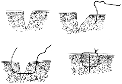 Figure 10-13. Technique for a box suture.
![]() Figure 10-14. Technique for an everting suture.
Figure 10-14. Technique for an everting suture. -
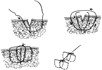
The “near-far/far-near”
suture may be used when the skin must be closed under some tension.
Begin with a deep box-type suture that is near the wound edge on one
side and far from it on the other. Complete the technique
P.179
with a box-type suture with the near and far sides reversed. Tie the suture so the skin edges are approximated (Fig. 10-16).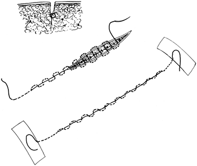 Figure 10-15. Technique for an intradermal (subcuticular) suture.
![]() Figure 10-16. Technique for a “near-far/far-near” suture.
Figure 10-16. Technique for a “near-far/far-near” suture. -
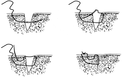
The Donati skin suture
technique, which was popularized by the AO/ASIF group, is another
modified mattress suture technique. It is useful when closing skin
under tension. The suture courses deeply across the wound and then goes
through the subdermal area without exiting the skin on the second side.
Begin with a deep box-type suture on the first side of the wound. Pass
back into the original side and exit between the wound and the original
entrance site (Fig. 10-17).
-
-

 |
|
Figure 10-17. Technique for a Donati suture.
|
AA, Heppenstall RB, Chance B, et al. Optimizing tourniquet application
and release times in extremity surgery: a biochemical and
ultrastructural study. J Bone Joint Surg (Am) 1985;67:303–314.
JP, Glassburn AR Jr, Talbott RD, et al. The effect of previous surgery,
operating room environment, and preventive antibiotics on postoperative
infection following total hip arthroplasty. Clin Orthop 1980;147:167–169.
JB, Volz RG. Efficacy of a topical antibiotic irrigant in decreasing or
eliminating bacterial contamination in surgical wounds. Clin Orthop 1984;184: 114–117.
AR, McClure AG, Skyhar MJ, et al. Local compression patterns beneath
pneumatic tourniquets applied to arms and thighs of human cadaver. J Orthop Res 1987;2:247–252.
RB, Scott R, Sapega A, et al. A comparative study of the tolerance of
skeletal muscle in ischemia: tourniquet application compared with acute
compartment syndrome. J Bone Joint Surg (Am) 1986;68:820–828.