
requiring emergent orthopaedic treatment. These fractures usually
result from a directly applied, high-energy force. Important local
concerns, such as limb deformity and injury to the surrounding soft
tissue, can be overshadowed by associated injuries and systemic
complications. However, femoral fracture management is important in the
initial injury phase and in determining the patient’s ultimate
functional outcome. The standard of care for stabilization of femoral
shaft fractures is intramedullary nailing. This chapter describes
intramedullary nailing of the femoral shaft.
The medial cortex is under compression, and the lateral cortex is under
tension. The femoral shaft is subjected to major muscular forces that
deform the thigh after a fracture:
the greater trochanter and abduct the proximal femur after trochanteric
fractures and proximal shaft fractures
proximal fragment in femoral shaft fractures by its attachment to the
lesser trochanter
strong axial and varus load to the bone by traction on the distal
fragment
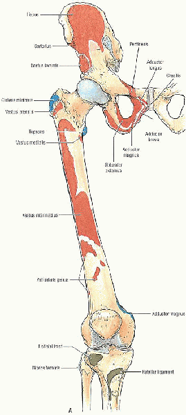
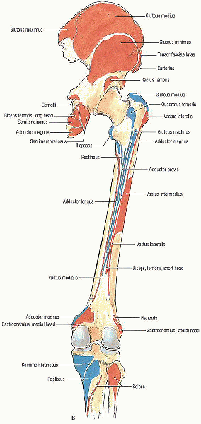
fascial compartments. The anterior compartment is composed of the
quadriceps femoris, iliopsoas, sartorius, and pectineus, as well as the
femoral artery, vein, and nerve and the lateral femoral cutaneous
nerve. The medial compartment contains the gracilis, adductor longus,
brevis, magnus, and obturator externus muscles along with the obturator
artery, vein, and nerve and the profunda femoris artery. The posterior
compartment includes the biceps femoris, semitendinosus, and
semimembranosus; a portion of the adductor magnus muscle; branches of
the profunda femoris artery; the sciatic nerve; and the posterior
femoral cutaneous nerve.
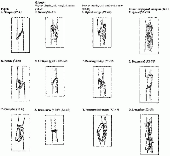
femur fractures. One such classification describes the fracture as (1)
open or closed; (2) location: proximal, middle, or distal one third;
supra-isthmic or infra-isthmic; (3) pattern: spiral, oblique, or
transverse; (4) comminuted, segmental, or butterfly fragment; (5)
angulation: varus, valgus, or rotational deformity; and (6)
displacement: shortening or translation.
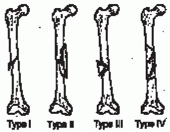
Type I and II fractures have stable bone contact between the proximal
and distal fragments and are considered length stable. Type III and IV
comminution results in no contact between the proximal and distal
fragments and requires static interlocking to maintain correct limb
length and rotation.
 |
|
FIGURE 36-1. Bones of the lower limb showing muscle attachments. A: Anterior view. (continued)
|
 |
|
FIGURE 36-1. Continued. B: Posterior view. (From Agur AMR, Lee MJ. Grant’s atlas of anatomy, 10th ed. Philadelphia: Lippincott Williams & Wilkins, 1999, with permission.)
|
 |
|
FIGURE 36-2.
The Winquist and Hansen classification of femoral shaft fractures is based on the amount of comminution. (From Wolinsky PR, Johnson KD. Femoral shaft fractures. In: Browner BD, Jupiter JB, Levine AM, et al, eds. Skeletal trauma, 2nd ed. Philadelphia: WB Saunders, 1998, with permission.) |
 |
|
FIGURE 36-3. The Orthopaedic Trauma Association (OTA) classification of femoral shaft fractures.
|
virtually all femoral shaft fractures in adults. Contraindications to
intramedullary nailing include active local or systemic infection;
adolescents with open growth plates in whom antegrade nailing through
the piriformis fossae can damage the blood supply to the femoral head,
causing osteonecrosis; a prolonged period of external fixation;
patients with very narrow medullary canals; and patients with
preexisting deformities that would preclude intramedullary nailing.
femur, including the femoral head, femoral neck, and knee on
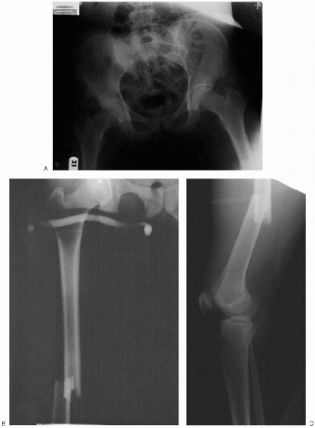
anteroposterior and lateral views (Fig. 36-4). Radiographs should be carefully inspected for intraarticular fracture
propagation and neoplastic disease. Preoperative radiographs of the
uninjured femur may be used to estimate proper nail diameter,
anticipated amount of reaming, and nail length for severely comminuted
fractures (Fig. 36-5).
Radiographic templates for preoperative planning are available from
most nail manufacturers. In cases involving a time delay from injury to
surgery, the surgeon should confirm that appropriate femoral length has
been obtained with traction; excessive intraoperative traction
resulting in pudendal or sciatic nerve palsy has been reported after
closed antegrade intramedullary nailing.
 |
|
FIGURE 36-4. Preoperative anteroposterior pelvis (A) and anteroposterior (B) and lateral (C) femoral radiographs show a displaced femoral shaft fracture.
|
patient and the extent of femoral comminution. Nevertheless, because of
a small but consistently reported percentage of complications caused by
nail fatigue, it is recommended that, if possible, an 11- or
12-mm-diameter nail be used.
 |
|
FIGURE 36-5. A and B:
Use of preoperative radiographs of the uninjured femur to estimate proper nail length. A radiolucent ruler is placed along the femoral shaft, and the distance from the anticipated proximal to distal extent of the nail is measured. |
-
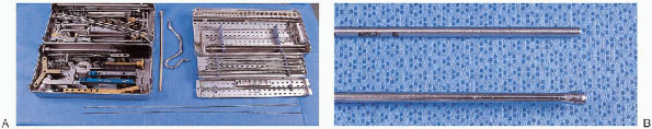
Curved awl
-
Ball-tipped and straight-tipped guide wires of identical length
-
Intramedullary reamer set
-
Guide wire exchange tube
-
Femoral nail instrument and implant sets
-
Image intensifier
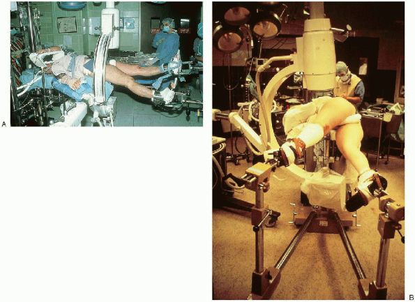
fracture fixation, the patient can be positioned supine or lateral on a
fracture table or radiolucent table (Fig. 36-7). I prefer to
position the patient supine on a fracture table. Supine positioning is
easier to set up than the lateral decubitus and better tolerated in
patients who have associated pulmonary injury or preexisting lung
disease. Use of the lateral decubitus position does, however,
facilitate identification and penetration of the nail entry point in
the piriformis fossae, which may be the most challenging step in
intramedullary nailing of a subtrochanteric fracture. Use of a fracture
table allows fracture reduction through sustained longitudinal
traction, with or without a skeletal pin. The design of most fracture
tables allows circumferential access to the extremity for manipulation,
surgical exposure, and imaging. Alternatively, intramedullary nailing
can be performed on a radiolucent table. Traction can be applied
manually or with the use of a femoral distractor. Set-up time is
minimal, and access to the piriformis fossa is improved by abducting
the limb. Disadvantages with this technique include difficulty
visualizing the hip and proximal femur in lateral projection,
difficulty reducing and holding the fracture alignment, and blockage of
the operative field by the femoral distractor.
 |
|
FIGURE 36-6. A: Selected equipment for intramedullary femoral nailing: TriGen instruments for implantation of a tibial or femoral nail (left tray, top and bottom); intramedullary reamer set (right tray, top and bottom); guide wire exchange tube and curved awl (between trays). B: Intramedullary femoral nailing instruments: straight-tipped (top) and ball-tipped (bottom) guide wires of identical length.
|
 |
|
FIGURE 36-7. Supine (A) and lateral (B) patient positioning on a fracture table.
|
 |
|
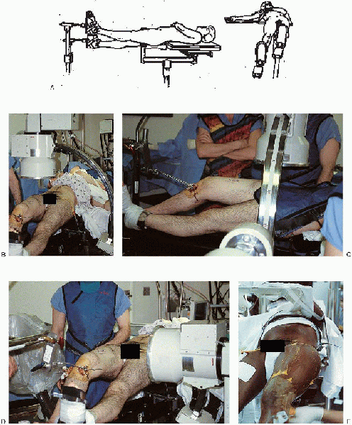
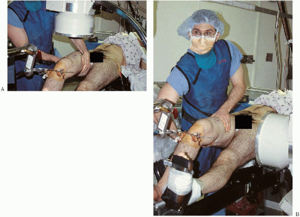
FIGURE 36-8. A and B:
With supine patient positioning on the fracture table, the contralateral lower extremity is placed into a heel-to-toe position, adjacent but inferior to the injured extremity. C and D: Positioning of the image intensifier to get anteroposterior and lateral views of the proximal femur. E: The patient’s trunk is adducted away from the operative side to facilitate access to the entry point and nail insertion. |
injured lower extremity is adducted with the hip flexed approximately
15 degrees. The contralateral lower extremity is placed into a
heel-to-toe position, adjacent but inferior to the injured extremity (Fig. 36-8).
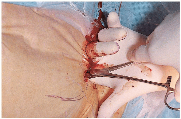
The patient’s trunk is adducted away from the operative side to
facilitate access to the entry point and nail insertion. Traction is
applied through a skeletal pin placed in the anterior aspect of the
distal femur (away from the anticipated nail position) or proximal
tibia.
 |
|
FIGURE 36-9. A and B:
Longitudinal traction is applied by means of proximal tibial or distal femoral pin traction, and fracture alignment is checked with the image intensifier. Manipulation of the leg helps to reduce an angulated fracture. |
fracture table and external manipulation. Longitudinal traction is
applied through use of proximal tibial or distal femoral pin traction,
and fracture alignment is checked with the image intensifier (Fig. 36-9). Occasionally, manipulation of the thigh by the surgeon or use of a crutch may help to effect fracture reduction. To
minimize the risk of a pudendal nerve palsy, the traction is decreased
during the preparation, draping, and proximal exposure. Frequently, a small-diameter
nail may be used in the proximal fragment to reduce a flexed and
externally rotated proximal fragment. Alternatively, many implant
manufacturers include a small-diameter rod in the nailing sets for this
purpose.
 |
|
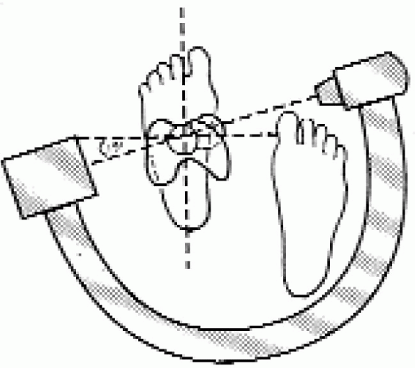
FIGURE 36-10.
Determination of rotational alignment using the image intensifier. The image intensifier is rotated to obtain a perfect cross-table lateral view of the femoral head and neck. The position of the image intensifier is recorded and the unit moved to the distal femur. The image intensifier beam is rotated 15 to 20 degrees internally, and the leg is rotated until a perfect lateral view of the distal femoral condyles and knee is obtained, reestablishing the correct anteversion of the femoral neck. |
neck anteversion averages 15 degrees in most adults. The image
intensifier is rotated to obtain a perfect cross-table lateral view of
the femoral head and neck. The position of the image intensifier is
recorded and the unit moved to the distal femur. The image intensifier
beam is rotated 15 to 20 degrees internally and the leg rotated until a
perfect lateral view of the distal femoral condyles and knee is
obtained, reestablishing the correct anteversion of the femoral neck.
Correct rotation of the distal fragment usually places the foot in 0 to
15 degrees of external rotation; with the patient placed on the
fracture table, however, the proximal fragment may externally rotate as
much as 45 to 50 degrees, requiring the foot to be turned out to match
this external rotation.
 |
|
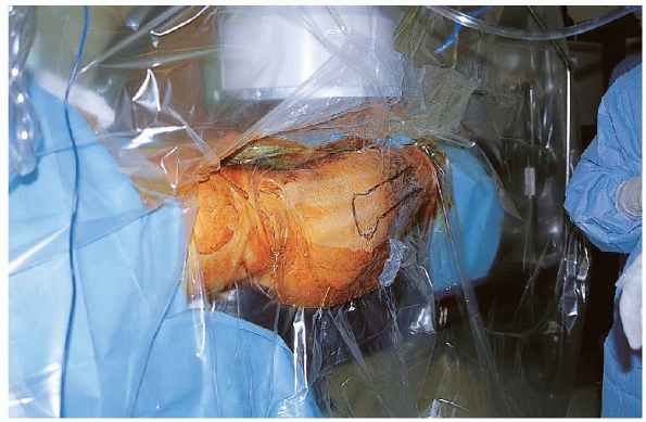
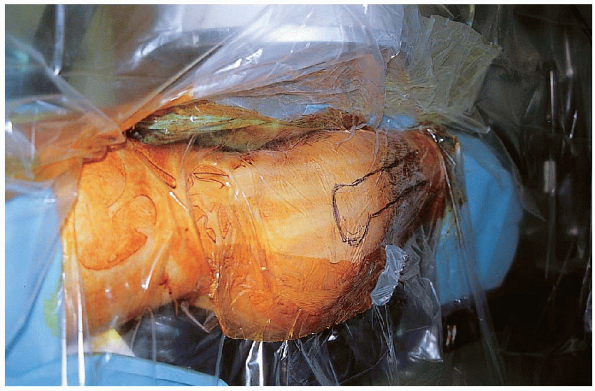
FIGURE 36-11. Use of the isolation screen.
|
 |
|
FIGURE 36-12. An oblique skin incision is made 4 to 5 cm proximal to the greater trochanter in line with the femoral shaft.
|
prepared from the rib cage to an area distal to the tibial tubercle.
The operative field is draped using an isolation screen (Fig. 36-11).
Alternatively, the lower extremity can be draped free, with the area
from the buttocks and lateral thigh to the popliteal crease exposed and
a sterile cover over the image intensifier.

of the proper entry portal is critical when using an intramedullary
nail, particularly with more proximal fracture patterns. For a
first-generation centromedullary nail,
the
entry portal should be in the middle of the piriformis fossae, in line
with femoral shaft in the sagittal and coronal planes (Fig. 36-14). A
lateral entry portal increases the risk of varus malalignment, and a
medial entry point increases the risk of iatrogenic femoral neck
fracture. When using second-generation (reconstruction) nail,
the entry portal should be moved anterior to facilitate placement of
the proximal locking screws within the femoral neck and head. A curved
awl or a cannulated reamer can be used to create the entry hole. I
prefer a 3.2-mm tip threaded guide pin from the sliding hip screw set ;
after its position is verified on the anteroposterior and lateral
views, the entry portal is enlarged with a cannulated reamer (Fig. 36-15).
 |
|
FIGURE 36-13. The fascia of the gluteus maximus is incised in line with its fibers, and the gluteus maximus is bluntly dissected.
|
 |
|
FIGURE 36-14.
The entry portal should be in the middle of the piriformis fossae, in line with femoral shaft on the sagittal and coronal planes (point B). When using a second-generation (reconstruction) nail, the entry portal should be moved anteriorly to facilitate placement of the proximal locking screws within the femoral neck and head (point A). |
 |
|
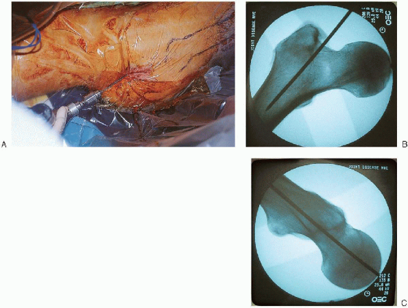
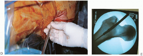
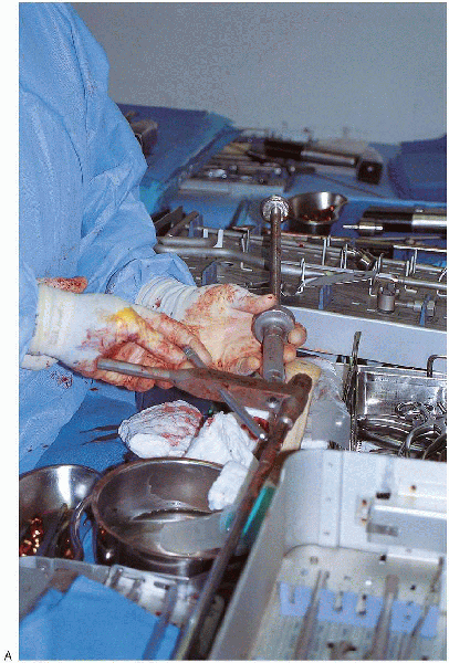
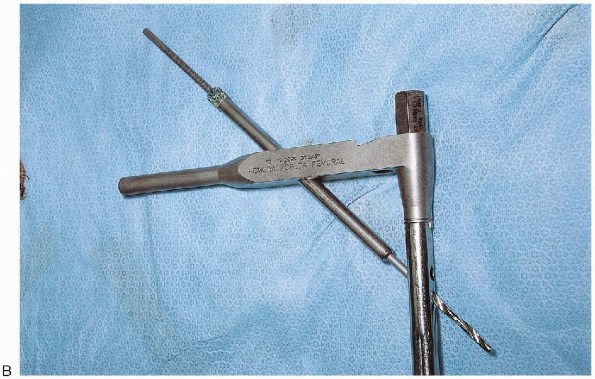
FIGURE 36-15. Use of a 3.2-mm tip-threaded guide pin from the sliding hip screw set to open the medullary canal (A); after its position is verified on the anteroposterior and lateral views (B and C), the entry portal is enlarged with a cannulated reamer (D and E). (continued)
|
creation of the entry portal, a ball-tipped guide rod attached to a
T-handled chuck is placed down the femoral canal to the fracture (Fig. 36-16).
Containment of the guide wire within the femur is confirmed with
anteroposterior and lateral fluoroscopic views. The fracture is
reduced, and the guide wire is advanced down the center of the femoral
canal to the epiphyseal scar (Fig. 36-17).
Itis important to centralize the guide wire in the sagittal and coronal
planes; otherwise, an angular malreduction may result when the
nail is inserted. If
the guide wire cannot be successfully advanced across the fracture
site, an internal fracture alignment device can be used to reduce the
fracture fragments. The proximal fragment is reamed to 10 mm and the
internal fracture alignment device inserted; this cannulated device is
used to directly manipulate the proximal fragment. After the fracture is reduced, the guide wire is advanced through the fracture alignment device into the distal fragment. If reducing the fracture closed proves difficult, the surgeon should not hesitate to perform a limited open reduction.
 |
|
FIGURE 36-15. Continued.
|
 |
|
FIGURE 36-16. A and B: Placement of a ball-tipped guide rod attached down the femoral canal. C and D: Containment of the guide wire within the femur is confirmed with anteroposterior and lateral fluoroscopic views.
|
 |
|
FIGURE 36-17. The fracture is reduced (A and B), and the guide wire advanced down the center of the femoral canal (C and D) to the epiphyseal scar (E and F).
It is important to centralize the guide wire in the sagittal and coronal planes; otherwise, an angular malreduction may result when the nail is inserted. |
 |
|
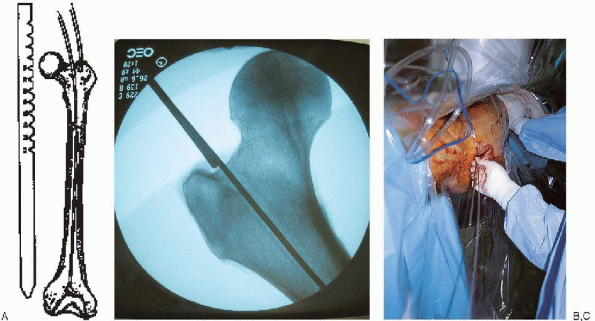
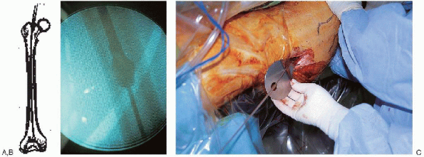
FIGURE 36-18. A: Determination of proper nail length using a radiolucent ruler or two identical length guide wires. B and C:
A second guide wire is overlapped with the portion of the reduction guide wire extending proximally from the femoral entry portal; this distance is subtracted from total guide wire length to determine nail length. |
 |
|
FIGURE 36-19. A and B: The femur is reamed over the ball-tipped guide wire in 0.5-mm increments until the desired canal diameter is achieved. C: A tissue protector is used at the entry portal to prevent soft tissue damage by the reamer.
|
of proper nail length can be made from preoperative planning and
verified using two identicallength guide wires or a radiolucent ruler.
In the guide wire method, a second guide wire is overlapped with the
portion of the reduction guide wire extending proximally from the
femoral entry portal (Fig. 36-18); this distance is subtracted from total guide wire length to determine nail length.
Alternatively, the radiolucent ruler is positioned over the anterior
femur, and image intensification used to make a direct reading of the
distance from the entry portal to the desired distal nail tip.
I prefer to use an 11- or 12-mmdiameter nail and to overream the canal
by 1 mm or, in cases of a large anterior femoral bow, 1.5 mm. If
the intramedullary canal is small or if significant chatter is
encountered during reaming of the femoral canal, a smaller-diameter
nail should be selected.
ball-tipped guide wire is replaced with a straight-tipped guide wire,
inserted using the medullary exchange tube to maintain fracture
reduction (Fig. 36-20). The selected femoral
nail is attached to the insertion jig; when properly assembled, the
femoral nail should have an anterior bow, and the proximal guide should
point laterally (Fig. 36-21). It
is important to verify that the proximal targeting jig aligns with
proximal nail holes before nail insertion; this can be done by
assembling the drill sleeves within the insertion guide and checking
that the drill bit smoothly targets the proximal nail screw holes.
 |
|
FIGURE 36-20. A to C:
The ball-tipped guide wire is replaced with a straight-tipped guide wire, inserted using the medullary exchange tube to maintain fracture reduction. |
The insertion handle is used to control rotation and direct nail
passage. When the nail can no longer advance manually, a mallet should
be used. The mallet should only be used on the
insertion driver and not on the proximal drill guide; striking the
guide can alter the alignment required for proximal targeting. As
the nail is advanced down the femoral canal, correct nail rotation
should be verified; the proximal insertion handle should be parallel to
or pointed toward the floor to facilitate distal locking screw
insertion. With the proximal handle pointed toward the ceiling, it is
difficult to place the x-ray beam of many image intensifiers parallel
to the distal screw holes, which complicates distal locking screw
insertion. To prevent nail incarceration, the surgeon should verify that the nail advances with each mallet blow.
During nail insertion, it may be necessary to retighten the bolts of
the proximal drill guide assembly before final nail seating.
the nail is fully seated and its position verified in the sagittal and
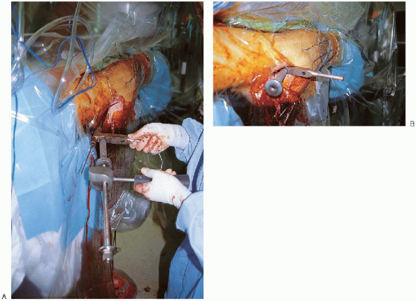
coronal planes, the interlocking screws are inserted. For standard
interlocked femoral nails, the proximal locking screws are inserted
through the insertion jig and are directed obliquely or transversely
from lateral to medial, depending on the nail manufacturer (Fig. 36-23).
Theproximal locking screw is bicortical and is inserted after predrilling.
The positioning of this locking screw depends on fracture geometry but
is usually at the level of the lesser trochanter. The
surgeon should avoid placement of the screw in the inferior femoral
neck, which could result in a stress riser effect and consequent
femoral neck fracture. The length of the locking screw can be determined directly from the drill bit. I
usually measure the length of the drill bit after it contacts the inner
aspect of the medial femoral cortex and add 5 mm to this measurement to
determine appropriate proximal locking screw length.
 |
|
FIGURE 36-21. A:
The selected femoral nail is attached to the insertion jig; when properly assembled, the femoral nail should have an anterior bow, and the proximal guide should point laterally. (continued) |
 |
|
FIGURE 36-21. Continued. B:
It is important to verify that the proximal targeting jig aligns with the proximal nail holes before nail insertion. This can be done by assembling the drill sleeves within the insertion guide and checking that the drill bit smoothly targets the proximal nail screw holes. |
 |
|
FIGURE 36-22. A and B: The nail is advanced manually down the femoral canal over the guide wire.
|
 |
|
FIGURE 36-23. A to D: Insertion of the proximal locking screws through the insertion jig.
|
locking is routinely advised with the use of interlocked femoral nails;
a static construct confers stability and is highly unlikely to lose
fracture reduction in the postoperative period. Brumback
et al. reported a 10.6% loss of reduction when interlocked femoral
nails were placed in a dynamically locked mode in fractures without
significant fracture comminution. Before insertion of the distal
locking screw, the fracture is reassessed to verify correct fracture
reduction, femoral length, and rotation. Distal locking screws are
inserted using a freehand technique. There are many ways of placing the
distal locking screws, but all require good image intensification (Fig. 36-24).
The image intensifier is positioned with the beam parallel to thedistal locking holes; with appropriate adjustment, the holes appear perfectly round. I prefer to use an extra-sharp, pointed trocar to open the lateral cortex of the distal femur.
The tip of the trocar is positioned in the middle of the locking hole
as visualized on the image intensifier. A small skin incision is made
at the tip of the trocar, and the tissue is dissected down to bone. The
tip of the trocar is repositioned in the middle of the locking hole and
the trocar placed on end parallel to the x-ray beam. After a halo is
seen completely surrounding the trocar, it is tapped through the near
cortex. Alternatively, the surgeon could use a radiolucent targeting
device, which is available from various manufacturers. The image
intensifier is then positioned in an anteroposterior direction and the
trocar drilled across the nail until it engages the opposite cortex.
Next, the image intensifier is positioned laterally to verify that the
trocar has gone through the nail. After verification, the trocar is
advanced through the far cortex and the length of the locking screw
determined. I usually estimate the length of the
locking screw based on the anteroposterior image intensifier view and
the known nail diameter. Alternatively, a depth gauge or a
second trocar of equal length can be used. The locking screw is then
inserted. A second distal locking screw is inserted in an identical
manner. Before wound closure, fracture reduction and nail position,
including all locking screws, are assessed radiographically in the
sagittal and coronal planes (Fig. 36-25).
 |
|
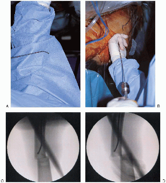
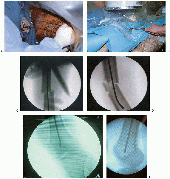
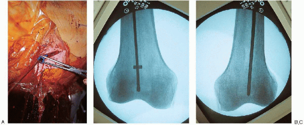
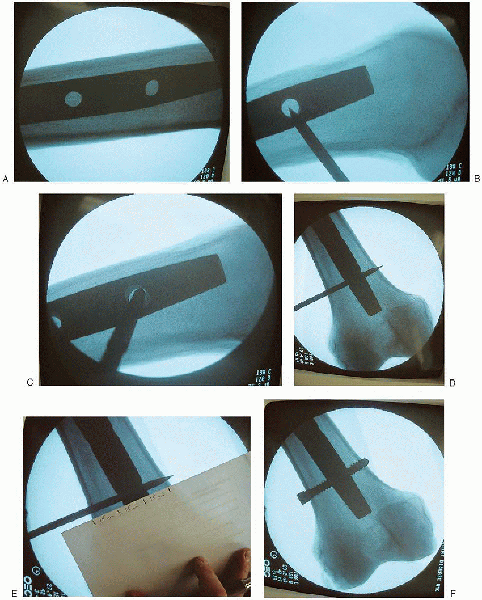
FIGURE 36-24. Insertion of the distal locking screws using a freehand technique. A:
The image intensifier is positioned with the beam parallel to the distal locking holes; with appropriate adjustment, the holes appear perfectly round. B: The tip of the trocar is positioned in the middle of the locking hole, as visualized on the image intensifier. The tip of the trocar is repositioned in the middle of the locking hole and the trocar placed on end, parallel to the x-ray beam. C: After a halo is seen completely surrounding the trocar, it is tapped through the near cortex. D: The image intensifier is then positioned in an anteroposterior direction and the trocar drilled across the nail until it engages the opposite cortex. E: After verification of the position, the trocar is advanced through the far cortex, and the length of the locking screw is determined. F: Insertion of the locking screw. |
 |
|
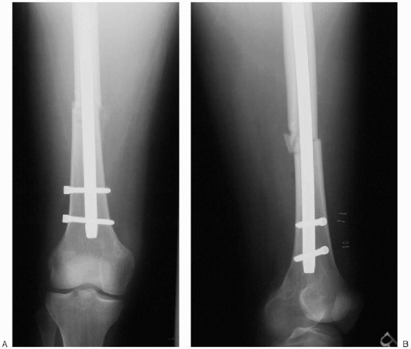
FIGURE 36-25. A and B: Final postoperative radiographs.
|
location and the amount of comminution, age of patient, preoperative
mobility, and extent of coexisting injuries. Early weight bearing is
encouraged for the patient with transverse or short oblique fractures
when there is stable contact between two major fragments so that weight
is transmitted through the bone. When comminution prevents transmission
of weight through the bone, the patient is instructed to partially bear
weight for 6 to 8 weeks to permit callus formation.
removal and wound inspection. Anteroposterior and lateral radiographs
are obtained to inspect the implant position, fracture alignment, and
progress of union immediately after
surgery
and at 6 weeks, 12 weeks, and 20 to 24 weeks. A set of radiographs is
obtained at 6 months to document adequate healing of the fracture. The
average uncomplicated femoral diaphyseal fracture unites in 3 to 5
months. Several months of exercise are required to achieve the ultimate
range of knee motion. The speed of recovery and degree of motion are
enhanced by early physical therapy.
Closed interlocking nailing of femora shaft fractures: assessment of
technical complications and functional outcomes of comparison of a
prospective database with retrospective review. J Orthop Trauma 1993;7:118-122.
Incidence of adult respiratory distress syndrome in patients with
multiple musculoskeletal injuries: effect of early operative
stabilization of fractures. J Trauma 1985;25:375-384.
The treatment of femoral shaft fractures using intramedullary
interlocked nails with and without reaming: a preliminary report. J Orthop Trauma 1997;11:89-92.