
tibia and can be caused by direct trauma or by torsional stress. The
diagnosis is based on the presence of deformity and on anteroposterior
and lateral radiographs. Associated injuries that must be excluded are
arterial injuries, compartment syndrome, and injuries to the ligaments
of the knee or ankle.
extremity is to return the patient to his or her preinjury level of
activity as soon as possible. For displaced tibial shaft fractures,
this is best achieved by intramedullary nailing. This chapter discusses
intramedullary nailing of the tibial shaft.
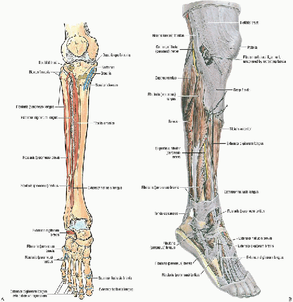
It has a subcutaneous anteromedial border and is bounded by four tight
fascial compartments. The nutrient artery of the tibia arises from the
posterior tibial artery, entering the posterolateral cortex distal to
the origination of the soleus muscle, at the oblique line of the tibia.
If the nutrient artery is disrupted, there is reversal of flow through
the cortex, with the periosteal blood supply becoming more important.
The fibula is responsible for 6% to 17% of the weight-bearing load. The
common peroneal nerve courses around the neck of the fibula, where it
is vulnerable to a direct blow or traction injury.
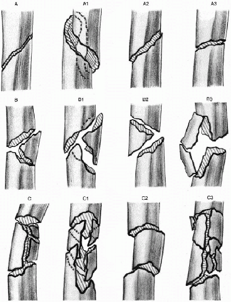
It may be best to describe the fracture in terms of (1) an open or
closed injury; (2) its anatomic location (i.e., proximal, middle, or
distal third); (3) the fragment number and position (e.g., comminution,
butterfly fragments); (4) fracture configuration (i.e., transverse,
spiral, or oblique); (5) angulation (e.g., varus or valgus, anterior or
posterior); (6) shortening; and (7) displacement and percentage of
cortical contact.
|
Type A: simple |
|
|
A1: |
spiral |
|
A2: |
oblique (>30 degrees) |
|
A3: |
transverse (<30 degrees) |
|
Type B: wedge (butterfly) |
|
|
B1: |
spiral |
|
B2: |
bending |
|
B3: |
fragmented |
|
Type C: complex (comminuted) |
|
|
C1: |
spiral |
|
C2: |
segmented |
|
C3: |
irregular |
patients with an open fracture; multiple injuries; an ipsilateral
fracture of the femur, ankle, or foot; vascular injury; compartment
syndrome; and unacceptable fracture position after closed reduction and
casting. An acceptable reduction includes less than 1.0 to 1.5 cm of
shortening and up to 5 degrees of angulation (e.g., varus or valgus,
anterior or posterior). Unstable fractures with high-grade soft tissue
injury, whether closed or open, require operative stabilization.
located in the middle two thirds of the tibia. Indications for
intramedullary nailing may be extended proximally or distally, but they
are associated with an increased risk of fracture malreduction.
Contraindications to intramedullary nailing include immature patients
with open physes, patients with very small medullary canals, or a
history of tibial osteomyelitis.
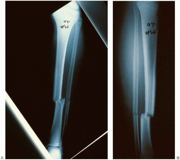
the fractured extremity, including the knee and ankle, are critical to
define the fracture and geometry of the tibial injury (Fig. 37-3).
The lateral radiograph should be carefully inspected and the size of
the intramedullary canal measured. An ossimeter can be used to measure
the tibia and to establish the length and diameter of the nail required.
 |
|
FIGURE 37-1. A: Anterior view of the tibia, fibula, and dorsum of the foot shows the muscle attachments. B: Anterolateral view of the muscles of the leg and foot. (From Agur AMR, Lee MJ. Grant’s atlas of anatomy, 10th ed. Philadelphia: Lippincott Williams & Wilkins, 1999, with permission.)
|
 |
|
FIGURE 37-2.
The Orthopaedic Trauma Association (OTA) classification of tibia fractures. (From Winquist RA. Tibial-shaft fractures: reamed intramedullary nailing. In: Wiss DA, ed. Master techniques in orthopaedic surgery: fractures. Philadelphia: Lippincott Williams & Wilkins, 1998:412, with permission.) |
 |
|
FIGURE 37-3. Anteroposterior (A) and lateral (B) radiographs demonstrating a fracture of the tibia and fibula.
|
 |
|
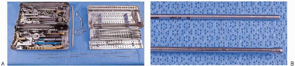
FIGURE 37-4. A: Selected equipment for intramedullary tibial nailing: TriGen instruments for implantation of a tibial or femoral nail (left tray, top and bottom); Intramedullary reamer set (right tray, top and bottom); guide wire exchange tube and curved awl (between trays). B: Intramedullary tibial nailing instruments: straight-tipped (top) and ball-tipped (bottom) guide wires of identical length.
|
 |
|
FIGURE 37-5.
Supine patient positioning on a radiolucent table with a bolster under the knee. The knee is flexed to permit access to the proximal tibia. |
-
Curved awl
-
Ball-tipped and straight-tipped guide wires of identical length
-
Intramedullary reamer set
-
Guide wire exchange tube
-
Tibial nail instrument and implant sets
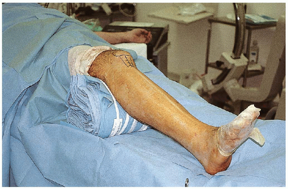
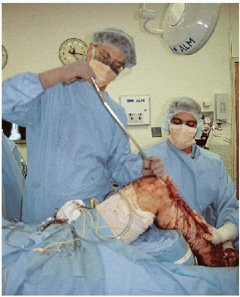
patient positioned supine on a radiolucent table or on a fracture
table. Supine positioning on a radiolucent table with a bolster under
the knee is the simplest technique and is my preferred method. The knee
is flexed over a radiolucent pad, which permits access to the proximal
tibia and visualization of the starting point (Fig. 37-5).
However, the disadvantage to this method of treatment is that it can be
difficult to obtain and maintain fracture length in addition to
controlling angulation and rotation.
 |
|
FIGURE 37-6. Manual reduction of the tibial shaft using a combination of longitudinal traction and an angularly directed force.
|
effective in maintaining length and rotation. With the fracture table,
the knee is flexed 90 degrees over a post, which is placed proximal to
the popliteal fossa to prevent compression of the vessels or peroneal
nerve. Tape can be placed around the thigh to prevent external rotation
of the extremity.
can be used with a pin placed proximally in the posterior tibia and
distally just above the ankle joint. In acute fractures, a unilateral
frame is usually adequate.
 |
|
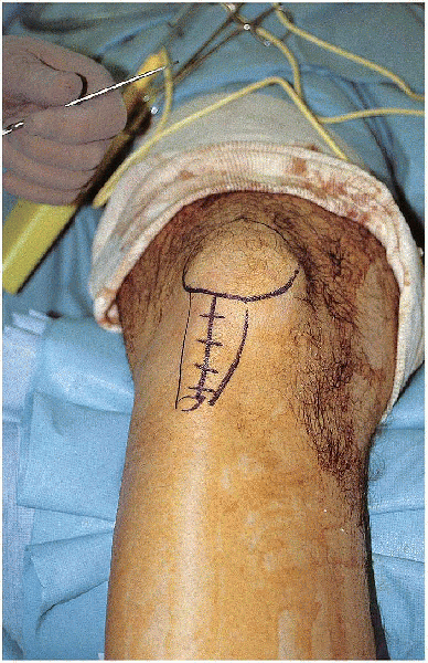
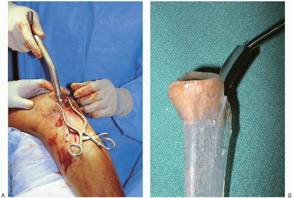
FIGURE 37-7. The incision extends from the tibial tubercle to the inferior aspect of the patella.
|
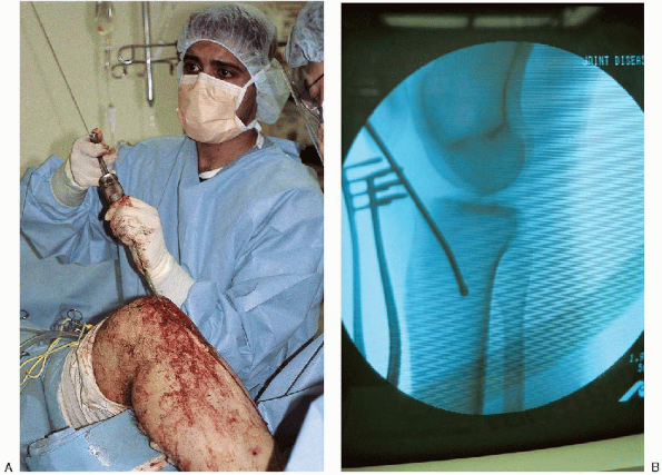
 A curved awl is used to open the medullary canal at the junction of the anterior tibia and knee joint (Fig. 37-9). It
is important to stay extraarticular, because backout of the nail may
impinge on the femoral condyle. It is equally important not to enter at
the tibia tubercle, because this leads to a more oblique
anteroposterior starting angle with a greater risk for penetration of
the posterior cortex with the nail. The exact starting point for
the awl is determined on the anteroposterior and lateral fluoroscopic
views. In midshaft and distal tibial fractures, the anteroposterior
starting point should be in line with the center of the tibial shaft.
On the lateral radiograph, the point of the awl should be just inferior
to the joint line. In proximal fractures, the
incision and starting point is just lateral to the patellar tendon;
this results in the nail abutting against the lateral tibial cortex,
which helps prevent translation and angulation.
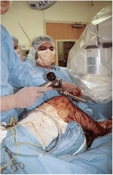
is helpful to place a small bend in the guide wire 2 cm from the tip.
This often facilitates passing of the wire across the fracture site.
A T-handle, which is used to control the bulb-tip guide, is placed in
the midportion of the guide wire. The bulb tip is initially aimed
posteriorly to enter the tibia and then immediately turned anteriorly
and passed down to the fracture site, avoiding penetration of the
posterior cortex proximally or exiting through the fracture site
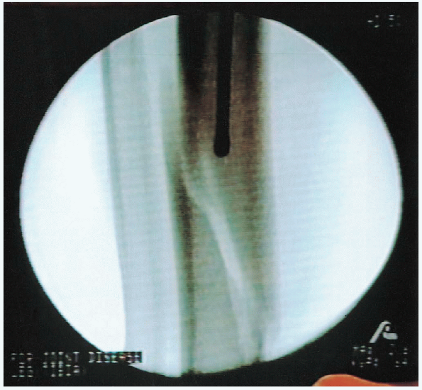
posteriorly. The guide wire is advanced to the fracture site (Fig. 37-11), the fracture is reduced, and the guide wire is
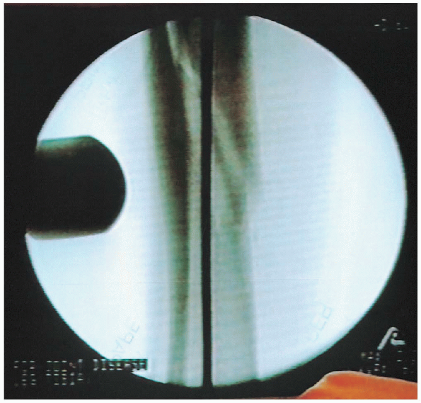
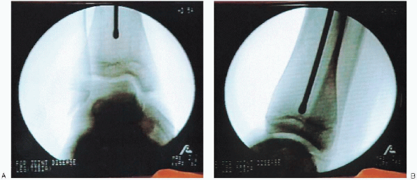
advanced under image intensification into the distal fragment (Fig. 37-12). It is impacted into the subchondral bone above the ankle (Fig. 37-13)
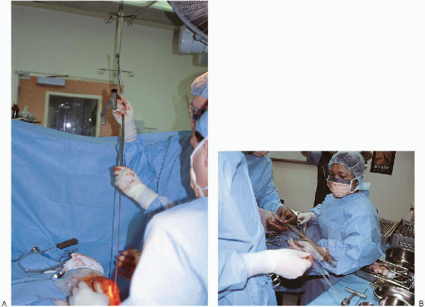
to stabilize the bulb tip and to aid in determining length. A second
bulb tip of identical length is placed at the joint line, and a long ruler is used to determine nail length (Fig. 37-14).
Another method to determine the nail length is to measure the tibia
externally with a long ruler with hatch marks and confirm it with the
image intensifier.
 |
|
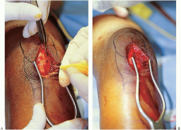
FIGURE 37-8. The medial aspect of the patella tendon is identified (A), and the patella tendon is reflected laterally (B).
|
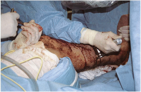
Reamingmust be done with sharp cutting reamers that dissipate heat and
pressure. To prevent soft tissue damage around the incision, a skin
protector should be used. A tourniquet should be avoided because of the increased risk for thermal heat necrosis. The surgeon starts with a small-diameter reamer and increases by 0.5-mm increments until cortical contact is reached. The fracture must be reduced as the reamer passes.
The operator must take care to prevent loss of the guide wire position
during each reamer introduction and removal. If the canal diameter
permits, it is mechanically beneficial to place a nail that is 10 mm in
diameter or larger. If necessary, an 8- or 9-mm nail may be used.
However, with smaller nails, the patient’s postoperative management may
need to be modified.
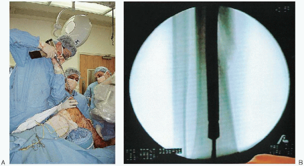
The bulb tip is removed, a straight tip guide wire is inserted, and the
plastic tube is removed. The nail is introduced down the tibial canal
over this guide wire (Fig. 37-17).
It is important to push posteriorly on the proximal end of the nail to minimize penetration of the posterior cortex. As the nail approaches the fracture, the fracture must be aligned in two planes. Thenail should be inserted in slight external rotation. If the nail is
allowed to rotate internally, interlocking occurs on the posteromedial
cortex proximally and distally, which is much more difficult than if
carried out on the flat surface of the tibia. To make targeting an
easier process, the nail should be externally rotated approximately 10
degrees in relation to the long axis of the tibia.
 |
|
FIGURE 37-9. A and B: A curved awl is used to open the medullary canal at the junction of the anterior tibia and knee joint.
|
 |
|
FIGURE 37-10. A and B: Insertion of a bulb-tip guide wire down the medullary canal.
|
 |
|
FIGURE 37-11. Advancement of the guide wire to the fracture site.
|
 |
|
FIGURE 37-12. Fracture reduction and guide wire advancement into the distal fragment.
|
 |
|
FIGURE 37-13.
Advancement of the guide wire to the subchondral bone above the ankle. The guide wire should be centered on the anteroposterior (A) and lateral (B) radiographs. |
 |
|
FIGURE 37-14. Determination of the tibial nail length. A:
A second guide wire of identical length is placed at the joint line and overlapped with the external portion of the reduction guide wire. B: The overlapped amount is subtracted from total guide wire length to determine the nail length. |
 |
|
FIGURE 37-15. A and B: Reaming of the intramedullary canal.
|
 |
|
FIGURE 37-16.
After intramedullary reaming, a plastic exchange tube is passed over the bulb tip and across the fracture site. The bulb tip is removed, a straight tip guide wire is inserted, and the plastic tube is removed. |
 |
|
FIGURE 37-17. The nail is introduced down the tibial canal over the straight-tipped guide wire.
|
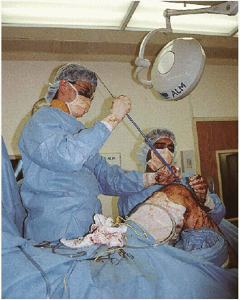
to avoid fracture distraction. In stable fracture patterns, traction
can be released when the nail tip is 1 cm past the fracture. This
allows fracture impaction and avoids distraction. Distal
counterpressure can also be used as the nail crosses the fracture to
prevent fracture distraction. As the nail is driven down the tibia, it
is important to reassess the accuracy of its length. The tibia should
be inspected proximally and distally. If the nail is too short or too
long, it should be removed and replaced with another nail.
 |
|
FIGURE 37-18. Final seating of the intramedullary nail.
|
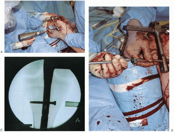
proximal and distal interlocking screws are inserted. Targeting devices
that attach to the intramedullary nail are very successful in placing
the proximal tibial locking screws (Fig. 37-19). Only one
proximal screw is necessary for fractures in the midshaft and below.
For proximal fractures, two screws are necessary in the proximal end of
the nail. For stable transverse or short oblique tibial fractures, the
use of a dynamic slot at the proximal end of the nail is beneficial to
allow impaction of the fracture. If there is any sign of comminution or
a spiral component to the fracture, the nail should be statically
locked.
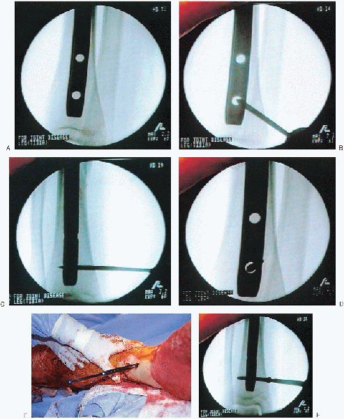
Proximal and distal locking screws are inserted from medial to lateral
in the subcutaneous border of the tibia. The freehand technique
requires targeting of the skin incision. The image intensifier is lined
up with the nail and tilted and rotated until a perfectly round hole is
visualized. It is helpful to move the C-arm head away from the tibia to increase the working space and aid in magnification of the hole.
The sharp point of the trocar-tipped pin is placed on the skin until it
is centered in the hole. A 1-cm stab wound is made directly over the
hole on the medial aspect of the tibia. The sharp, pointed pin is again
placed on the bone until it is centered in the hole. It is brought into
the longitudinal axis and checked with fluoroscopy to ensure that it is
centered in all planes. The pin is then passed into the tibia.
Fluoroscopy is used to verify that the pin has corrected targeted the
nail and the pin drilled through the far cortex. The length for the
locking is determined using a second pin of the same length or a depth
gauge, or it is estimated using the image intensifier. The screw is
then inserted. The screw should be 5 mm too long, because this makes removal of a broken screw easier.
A lateral radiograph should be checked again to be absolutely certain
the screw is in the nail and has not moved anteriorly or posteriorly.
 |
|
FIGURE 37-19. After the nail has been inserted to the appropriate depth, the proximal tibia is drilled (A), the length of the locking screw measured, and the locking screw inserted (B and C).
|
closure, it is important to again verify the adequacy of the fracture
reduction, including rotational alignment. If necessary, the patient is
checked for increased compartment pressure. Final radiographs are taken
with the patient under anesthesia.
deformity. The patient remains in a splint until the swelling
decreases. In a reliable patient with a stable fracture pattern and a
dynamic locking screw, toe-touch weight bearing is desirable, with
progressive weight bearing over the first 4 weeks. For an unstable
injury pattern or an unreliable patient, avoidance of weight bearing is
recommended for the first 6 to 8 weeks.
 |
|
FIGURE 37-20. A freehand technique is used to insert the distal locking screws. A: The image intensifier is lined up with the nail and tilted and rotated until a perfectly round hole is visualized. B: The sharp point of the trocar-tipped pin is placed on the skin until it is centered in the hole. C: The pin is then brought into the longitudinal axis and passed into the tibia. D: Fluoroscopy is used to verify that the pin has correctly targeted the nail and that the pin drilled through the far cortex. E:
The length for the locking screw is determined using a second pin of the same length or a depth gauge, or it is estimated using the image intensifier. F: The locking screw is then inserted. |