
II – FRACTURES, DISLOCATIONS, NONUNIONS, AND MALUNIONS > General
> CHAPTER 11 – PRINCIPLES OF INTERNAL AND EXTERNAL FIXATION
combines five chapters from the second edition of Operative
Orthopaedics, written by Timothy J. Bray and David C. Templeman (screw
fixation), Fred Behrens (external fixation), David H. Gershuni (wire
and pin fixation), Thomas P. Rüedi (plate fixation), Harry B. Skinner
(materials), and myself. Much of the original material by these authors
has been retained in this chapter, and I wish to acknowledge and thank
them for their contributions.
employs an incredibly broad range of techniques, from fine
microvascular surgery to bone fixation implants, to large metallic and
polymeric composite implants for joint replacement, to sophisticated
methods of external fixation involving all regions of the skeleton.
Successful use of these implants and devices requires sophisticated
technical knowledge on the part of the surgeon, as well as respect for
the biology of the tissues being handled, for the best chance of a
successful result. The surgeon must be certain that the indications for
surgery are appropriate and that the patient is suitable for the
operation: Even the best-performed procedure will fail if the
indications are not correct and if the patient cannot benefit.
fixation implants are critical to achieving bone union in the
appropriate position and to avoiding implant failure. It is essential
that resident and neophyte surgeons master the general principles and
that mature surgeons constantly remind themselves of them, particularly
when they are employing fixation techniques that they do not perform
often.
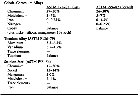
presence of a constituent element that has the ability to form an
adherent oxide coating that is stable and chemically inert. Materials
that do not form stable oxides or that permit the oxide to become
detached from the underlying metal, such as common carbon steel, are
not biocompatible and continue to undergo degradation in the body. The
common metallic alloys [e.g., cobalt chromium (ASTM F75-82, ASTM
799-82), titanium alloy (ASTM F136-79), and stainless steel (ASTM F55,
F56)] have at least one element that forms an adherent oxide coating.
The composition of these alloys is shown in Table 11.1. Detailed specifications of the composition are given in the American Society for Testing and Materials (ASTM) standards.
 |
|
Table 11.1. Nominal Compositions of Implant Alloys
|
use of the material. For example, if ductility is not a requirement,
carbon is used to strengthen cobalt-chromium alloy (F75-82), although
carbon reduces the alloy’s ductility. Other phases present in each
alloy tend to stabilize the crystal structure. Forged cobalt-chromium
alloy is strengthened by nitrogen as a minor impurity. Certain elements
are deleterious to the properties, such as oxygen in a titanium alloy,
which tends to make it brittle. Similarly, carbon in stainless steel
decreases ductility unless it is allowed to precipitate in the grain
boundaries as chromium carbide, where it decreases resistance to
corrosion.
elements together to produce a liquid solution that subsequently
becomes a solid solution of each element in the matrix after cooling.
This material is shipped as a bar, rod, or plate for further processing
by the implant manufacturer. Titanium alloy can be shaped by machining
from bar stock or sheet stock; stainless steel implants can be produced
the same way. After initial forming of the more ductile version of the
cobalt-chromium alloys, forging significantly strengthens the alloy and
brings it to its final shape by applying mechanical work. The casting
process can be used for titanium alloy or cobalt-chromium alloy to
produce intricate shapes. A wax mold of the prosthesis is coated with
ceramic and fired. The wax melts out of the ceramic mold (i.e., lost
wax process); after cooling, liquid metal is poured into the ceramic
shape and allowed to solidify. Final shaping is done by machining and
grinding. Machining and forging done under appropriate conditions do
not diminish the mechanical properties of the alloy. However,
investment casting typically weakens the material by causing an
increase in the grain size. This mostly affects the fatigue life,
because for most materials the fatigue strength is inversely
proportional to grain size.
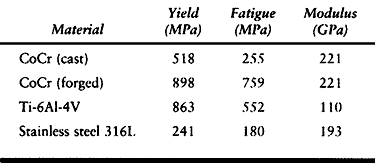
deformation and plastic or permanent deformation. Deformation at
strains lower than this level obey Hook’s law, which states that the
elastic modulus (Young’s modulus) is the proportionality constant in
the linear portion of the stress-strain curve below the yield point.
Fatigue strength refers to the ability of a material to resist
repetitive loading. Typical yield and fatigue strengths and elastic
moduli are presented in Table 11.2.
 |
|
Table 11.2. Typical Yield and Fatigue Strengths of Metal Alloys Used in Orthopaedic Surgery
|
material generated by the attraction of atoms within the material, and
it has essentially no variation with thermal or mechanical history.
Fatigue strength, however, can be significantly improved or diminished
by heat treatment. Cast cobalt-chromium alloy has a fatigue strength of
about 255 megapascals (MPa), which is only about twice that of the cast
stainless steel used in total hip prostheses in the early 1970s that
failed in fatigue. Titanium alloy, although quite strong in fatigue
strength in the “as received” or forged condition, can undergo
significant deterioration of its fatigue properties as a result of
applying a porous coating. Failure is caused by the creation of stress
concentration sites by the porous coating, and the grain growth caused
by the heat treatment used to apply the porous coating. Much of the
deterioration in properties of titanium alloy can be alleviated by the
use of a diffusion bonding process that lowers the temperature of
sintering. The notch sensitivity problem is managed by design
modifications that remove the porous material from areas subjected to
tensile loading. These concerns regarding the effect of porous coating
do not apply to implants for internal fixation.
the Rockwell test or the Vickers test, in which the material is
indented by a very hard object. The resistance to this plastic
deformation indicates the tensile strength of the material and its wear
properties. These tests are suitable for metallic alloys.
used material for bone fixation implants. The 3.16L alloy is still used
most commonly; however, other stainless steel alloys are also in use
and provide useful characteristics such as increased strength in hip
fixation implants, which can be subjected to high bending loads and
fatigue stress because of delayed healing (Table 11.1).
A major concern about stainless steel implants has been their
stiffness, which is approximately seven times that of human bone.
Uhthoff and Dubus (103) and others (16,27,63)
have demonstrated in animal experiments that when rigid internal
fixation is applied with stainless steel implants, prolonged exposure
of the bone can lead to porosis and weakening of the bone due to stress
protection. This is also seen in total joint arthroplasty, particularly
about the proximal portions of the stem in the femoral components of
total hip arthroplasty. Perren et al. (81,82)
have shown that the porosity and weakening observed is in part due to
the revascularization response resulting from the surgical procedure
itself; in spite of this, however, stress protection remains a
significant problem, particularly where the size and stiffness of the
implant is significant compared to that
of the bone. Chapman et al. (27),
in a review of 174 forearm fractures, found no refractures of the
radius or ulna after removal of AO 3.5 mm dynamic compression (DC)
plates, whereas in all three patients in whom the larger narrow DC
plates and 4.5 mm screws were used, refractures occurred either through
the screw holes or the fracture site.
for plates and nails that is closer to bone in its mechanical
characteristics, yet would be stiff enough to permit fracture healing
and strong enough to avoid fatigue failure prior to fracture union.
Titanium and its alloys, widely used in military aircraft and
submarines, have proven, in part, to meet this need. Most manufacturers
have used a titanium alloy containing 6% aluminum and 4% vanadium (6-4
titanium). The mechanical characteristics of commercially pure (CP)
titanium were not suitable for internal fixation implants until
recently; however, the AO group has used plates and screws of CP
titanium, which have proven to be clinically useful. By utilizing
particular forging and other techniques, they have been able to render
the CP titanium sufficiently strong. Other alloys of titanium,
particularly beta alloys, offer even better mechanical properties for
internal fixation implants than the 6-4 titanium, and some of these are
listed in Table 11.1. Overall, titanium alloys
are approximately twice as flexible as stainless steel and at least
one-third stronger. A primary disadvantage of titanium is that it is
difficult to manufacture, which increases costs. Also, it is more
brittle than stainless steel: Cracks occurring from notches in the
metal tend to propagate much more easily than in stainless steel, which
influences implant design and how the surgeon uses the implants.
Titanium alloys become particularly useful in smaller implants, such as
nonreamed intramedullary nails, and in smaller plates, which employ
smaller-diameter screws, where the superior strength of the titanium
results in much less screw and nail breakage compared with stainless
steel. In spite of the increased cost, most major implant manufacturers
today offer bone fixation implants composed of titanium. Some entire
implant systems, both plates and intermedullary nails, are offered in
titanium.
than stainless steel, which has a tendency to experience crevice
corrosion at the contact point between screw heads and plates. Plate
failure can take place through these corrosion pits. Titanium
aggressively forms an oxide, which provides superior passivation of the
implants. I have removed numerous titanium plates and screws and have
never seen any visible evidence of crevice corrosion.
metallic ions into the local soft tissues and general circulation.
Although concerns have been raised about the potential toxic or
carcinogenic effects of these minute amounts of ions, and sarcomas have
been described in association with implants, no evidence has been
presented that implants are a significant health risk to patients. On
the other hand, current implant materials have been used for
approximately 60 years. Whether exposure to these implants for up to 80
or 90 years in our long-lived population will produce diseases is not
yet known. When placing these implants in children and young adults, a
discussion with patients and their parents regarding this issue is
appropriate. If concerns are expressed after implantation, and removal
of the implant will not incur unacceptable risks, then removal is
usually advised.
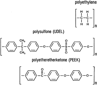
a routine basis. These are ultrahigh-molecular-weight polyethylene
(UHMWPE), polypropylene, polytetrafluoroethylene (PTFE, Teflon), and
polymethylmethacrylate. Other polymers show promise as matrix materials
for composite biomaterials, including polysulfone (UDEL),
polyethersulfone, and polyetheretherketone (PEEK). Their chemical
structures are shown in Fig. 11.1.
 |
|
Figure 11.1. Chemical structures of implant polymers.
|
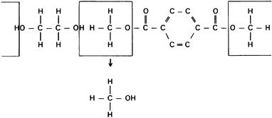
produce addition or condensation reactions. Condensation reactions
produce polymers by a combination of an organic acid and an organic
base to produce water or an alternative third compound (Fig. 11.2).
Reactive moieties on both ends of each type of molecule permit the
reaction to grow long chains. Additional polymerization produces the
polymer chains by adding one more link to a chain that was begun by an
initiator molecule reacting with a carbon double bond, such as found in
ethylene. Most implant
polymers are thermoplastic, because they can be melted and cooled until solid again with no composition change.
 |
|
Figure 11.2. A condensation reaction showing the method used to produce polyester (Dacron).
|
possible, molding of granules of a polymer under heat and pressure,
called compression molding, is more common for production of
polyethylene components. Machining of implants from stock is another
technique that can be used. Both methods produce acceptable articular
surfaces for implants.
for metallic implants, but their interchangeability is not as great.
Polypropylene is used as a ligament augmentation device for knee
reconstructive surgery, UHMWPE is used as the bearing surface in total
joint arthroplasty, and Teflon is expanded to form a Gore-tex material
used in knee reconstructive surgery. Polymethylmethacrylate is
partially polymerized, provided as granules, and combined with monomer
and an initiator to form a final polymerized mass (e.g., Zimmer bone
cement). When copolymerized with polystyrene, polymethylmethacrylate is
used in a similar manner to form Simplex-P (Howmedica, Rutherford, NJ).
(copolymers of the two acids), and polydioxanone find their main uses
as resorbable suture materials under the brand names Dexon (Davis and
Geck; US Surgical, Norwalk, CT), Vicryl, and PDS (both manufactured by
Ethicon, Johnson and Johnson, Somerville, NJ). These materials are also
available as resorbable pins, primarily for fracture fixation in the
hand, foot, ankle, and skull (3). These
materials can be made relatively stiff and are slow to resorb.
Polylactic acid is now available as screws and pins because its slow
rate of resorption may reduce the level of inflammatory response.
Attempts at improving the stiffness of polylactic acid have included
mixture with hydroxyapatite fibers.
produced by high-temperature processing. Typically, ceramics have high
thermal and electrical resistance and high elastic modulus, low
ductility, and low tensile strength. Excellent biocompatibility results
from chemical inertness.
strengths, but brittle failure occurs after minor plastic deformation.
Although the failure strength is quite high in many cases, relatively
low failure stresses can occur occasionally.
but they have not proven practical because of the inability to conform
them to the bone, and because of their high failure rate caused by
their brittle nature. Because of the unique characteristics of
ceramics, they enjoy much more practical application in the bearing
surfaces of total joint replacement prostheses and in the coatings of
prosthetic implants where direct bone–implant ingrowth is desired.
which the mechanical performance of the composite is superior to that
of either component alone. In man-made composites, usually one
component is a fiber and the other is a matrix material. Bone itself
achieves most of its mechanical properties as a natural composite
material composed of calcium phosphate ceramics in a highly organized
collagen matrix.
made by an orthopaedic surgeon, was the plaster of Paris bandage. This
has been refined to fiberglass with a polymeric matrix in the current
synthetic casting materials. A composite for internal prosthetic
applications is based on the addition of chopped carbon fiber to
improve the mechanical properties of polyethylene components.
must be biocompatible. Three potential matrix materials that have
undergone at least preliminary biocompatibility studies are
thermoplastic and have similar structures (Fig. 11.1).
These are UDEL, polyethersulfone, and PEEK, discussed above. The fiber
materials strengthen and stiffen the matrix and can be used as chopped
fibers or as long fibers. The chopped fiber material usually produces a
composite that is isotropic, having stiffness and strength properties
that do not vary with direction. The long fibers can be woven, wound,
or formed in many geometric orientations to provide desirable
mechanical properties. Only carbon fiber is being studied for
orthopaedic applications.
which all the fibers run in one direction and are held together by a
thin coating of the polymer matrix material. It is produced by passing
the fibers through the polymer, allowing it to be coated, and
subsequently sticking the layers together and pressing them. This
laminate is combined with other laminates to form a bulk composite; the
properties of this composite vary depending on the orientation of each
layer of the laminate. The primary direction of the fibers is called
the zero direction, and other layers, or laminae, are oriented in
relation to this (e.g., 0°, 45°, -45°, 90°, +30°, and -30°) to vary the
properties of the polymer. A polymer that has equal numbers of layers
in the 0°, 45°, -45°, and 90° orientations is called a pseudoisotropic
polymer because the mechanical properties in any direction in the fiber
plane are the same. An alternative means of producing a composite
structure is to wind one or more continuous fibers in a particular
orientation to form the desired prosthetic shape.
strength and the modulus. The strength generally mirrors the modulus,
and both of these depend on the orientation of fibers. The elastic
modulus can be estimated for laminated structures from the two “rules
of mixtures.” The modulus parallel to the fibers (Eparallel) is proportional to the amount of fiber in a simple linear relationship:
are the volume fractions of the fiber and matrix, respectively. In the
range of typical polymer fiber used in a laminate of 0.4–0.7 volume
fraction fiber, the elastic modulus varies linearly in that range
parallel to the fibers. The modulus relationship perpendicular to the
fibers is more complicated and less applicable to all composites:
radiolucent, roentgenographic examination of fractures fixed with
external fixation devices made of these materials can be performed with
relative ease. Similarly, halo rings made of these materials are
compatible with magnetic resonance imaging, allowing studies of the
brain and cervical cord to be performed.
composites have been used experimentally for internal fixation. Their
potential advantages include radiolucency (making observation of
fracture healing easier), the ability to vary the modulus of the
material, and the potential for using an absorbable polymer. None of
these materials are currently in clinical use because of the inability
to modify the shapes of the implants intraoperatively to fit the bone;
because of liberation of carbon fibers into the adjacent tissues; and
because the difficulties of predicting the resorption of polymers in
larger load-bearing implants, as opposed to screws and pins, has thus
far precluded their use for these larger implants. No doubt, implants
in this category will be available in the future, perhaps even
containing bone inductive proteins.
were used for fracture fixation. Later, silver wire was introduced by
Lister to treat a patellar fracture. Parham and Martin (77)
described steel bands used around the shaft of fractured long bones in
1913, and in 1922 Johnson developed stainless steel, which is the
material still used for most types of wire and pin fixation. This form
of fixation includes fine Kirschner wires, larger Steinmann pins, and
flexible wire used for provisional and definitive fracture
stabilization, osteotomy fixation, and skeletal traction.
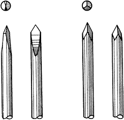
Germany, was the first to use thin wire pins for fracture management,
in 1909. Kirschner, or K- wires are manufactured in lengths from 7 to
31 cm and in diameters from 0.6 to 3.0 mm. They may be smooth or
threaded, but threaded wires have poorer bending strengths for a given
pin diameter and may be difficult to remove at a later date. The wire
may be pointed at one or both ends. In the latter case, the pin can be
inserted antegrade from the fracture site to exit from the distal
fragment and then retrograde back into the proximal fragment. K-wires
may be trocar or diamond pointed (Fig. 11.3). The trocar point
is somewhat easier to insert into dense cortical bone and there is less of a tendency to overheat.
 |
|
Figure 11.3. Ends of Kirschner wires or Steinmann pins with trocar points on right and diamond points on left.
|
introduced with a power drill and a pin stabilization system, which may
be a telescopic guide attached to the end of the drill chuck, or an
external guide with a handle. The drill itself may have the capability
of rapid locking and release of the wire; advancement therefore can be
made from the barrel of the drill, which acts as the guide.
Small-diameter pins can be inserted through large bore needles. An
alternative is to introduce a gentle bow into the wire while drilling.
This prevents oscillation of the wire. Two disadvantages of this
technique are that the direction of the wire may be more difficult to
control and the wire will overheat more rapidly. When K-wires are used,
wire cutters and instruments for wire bending are required. The wire
benders may be simple metal tubes into which part of the wire is
inserted before being manipulated, or special pliers can be used (Fig. 11.4).
 |
|
Figure 11.4. Instruments for wire bending. A: A metal tube with a flanged end. B: Special pliers.
|
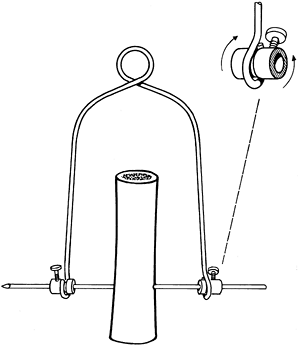
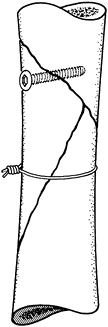
flexible, but the wire may be stiffened by applying tension with a
traction bow. The construct is thus made strong enough to apply a load
of approximately 20 kg, providing the bone is able to sustain this
weight (Fig. 11.5).
 |
|
Figure 11.5. Kirschner wire tensioner and traction bow.
|
skeletal traction, particularly in children, in whom smaller traction
loads are required and the cosmetic advantages of a smaller skin entry
point pertain. K-wires can be used in any of the common sites for
skeletal traction in the treatment of extremity fractures such as the
upper end of the tibia, the lower end of the femur, the olecranon, and
the digits. In children, passage of traction pins across the upper
tibia risks damage to the physis, resulting in its partial closure and
a subsequent growth deformity. If the proximal tibia must be used, the
wire must be inserted posterior and distal to the physeal line.
unit area directed against the bone by the K-wire is greater than that
exerted by a larger-diameter pin. Osteopenic bone is therefore a
relative contraindication to use of a K-wire for traction. See Chapter 10 for additional details.
fractures, especially in the presence of comminution, in which the
definitive fixation of two fragments may impede the subsequent
reduction of the rest of the fracture, is that the fracture be
initially provisionally fixed. K-wires are particularly
useful,
and many of them may be used in combination, with little damage to the
bone or its vascularity. They may be used alone or in combination with
bone-holding forceps or cerclage wires. A complicated fracture can be
fully and accurately reduced and temporarily fixed with K-wires.
Radiographs may then be taken on the operating room table to
demonstrate the anticipated result or to demonstrate any defects in the
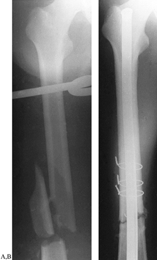
reduction and facilitate their correction (Fig. 11.6).
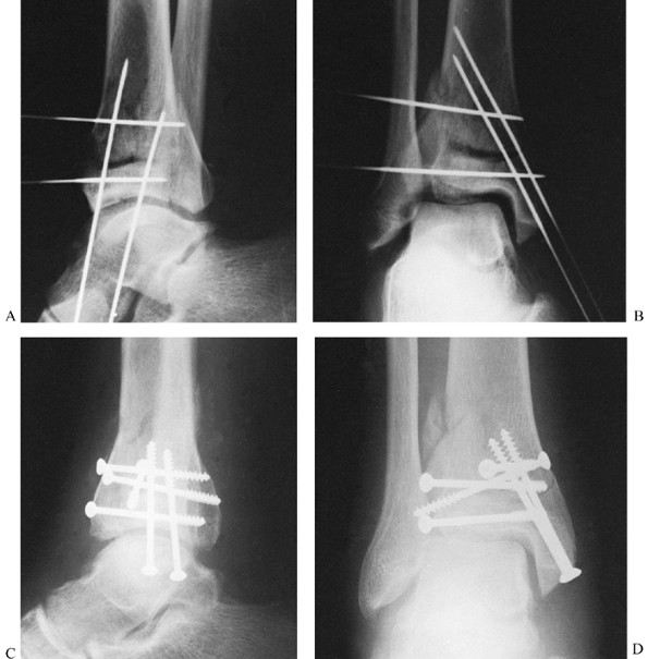 |
|
Figure 11.6. Tibial plafond fracture. A: Lateral radiograph shows provisional Kirschner wire fixation. B: AP radiograph shows provisional Kirschner wire fixation. C: Lateral radiograph after definitive screw fixation. D: AP radiograph shows definitive screw fixation.
|
provisional K-wire fixation to prevent the wires from interfering with
the later exchange to the definitive fixation with, for example, plates
and screws. Where K-wires are to be replaced by lag screws, introduce
the wires in the same direction that will be used later for the screw
fixation. Nonparallel K-wires will interfere with production of
satisfactory compression by lag screws across the fracture site (Fig. 11.6).
If crossed wires must be placed, remove them after the screw is in
place and before final compression. A simple trick to facilitate plate
application in the presence of multiple K-wires is, first, to place the
plate on the bone and mark the location of the holes on the bone with a
marking pen. Then, insert all the K-wires through the location of the
holes.
subsequent loading on a fractured bone is anticipated to be small
because the fracture is close to a joint or if the overall length of
the bone is not great. Thus, intra- and extraarticular fractures of the
phalanges, metacarpals, and metatarsals, and other bones of the carpus,
tarsus, and distal radius, may be stabilized with crossed Kirschner
wires.
-
Insert the first K-wire at right angles to the fracture plane.
-
Compress the fracture fragments and place a second K-wire obliquely to lock and maintain the compression (Fig. 11.7).
In the fixation of transverse phalangeal fractures, it has been found
that four crossed wires provide the strongest fixation; and in oblique
phalangeal fractures, three wires at right angles to the fracture
provide the best stabilization (106).
Stabilization with K-wires in these cases must almost always be
supplemented and protected by plaster-cast fixation, but early motion
is important.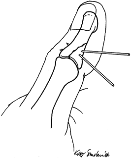 Figure 11.7.
Kirschner wire fixation of an intraarticular phalangeal fracture. One
wire is inserted at right angles to the fracture line, and the second
wire locks the reduction by its oblique insertion.
supracondylar fractures of the humerus in children: After closed or
open reduction, two K-wires inserted from the lateral side can maintain
good reduction when combined with external cast immobilization (see Chapter 164).
proximal end of the wire is left straight, there is a significant
likelihood of migration of the wire into or from the bone. Therefore,
the exposed end of the wire should always be bent with an appropriate
instrument if it will be left buried. If only a very small segment of
the wire is left exposed above the surface of the bone, it may be very
difficult to find later when metal removal is required. Another
alternative is to leave the end of the wire longer and just under the
skin to facilitate removal. Pressure on the skin from within (and
possibly from without due to dressings or plaster casts) may produce
skin necrosis and infection around the wire tip. It is therefore
recommended that either the wires be left buried with a bent end to
facilitate removal, or the tip of the wire be left protruding by a
centimeter or so from the skin. Prevent tension on the skin around the
wire and protect it from unwanted blows. Either cap the wire with a
commercially available wire cap or bend the end of the wire over. The
former is preferable as it prevents catching the end of the wire on
clothing. Reaction of the skin around the thin wire is minimal and
infection unusual as long as it is stable in the bone. Subsequent
removal of the pin is almost always easy and relatively pain free. In
situations where K-wires are used in a tension band construct and
functional postoperative therapy will be instituted, bend the ends of
the wires into a U shape and impact them into the bone.
Switzerland, introduced pins that were thicker than those of Kirschner
but otherwise very similar.
lengths of 150 to 300 mm. The pointed end is usually of the trocar or
diamond-pointed design (Fig. 11.3), but cove points are also available (Fig. 11.8). The
cove point has a positive rake angle, which cuts bone rather than
scraping it as occurs with the trocar and diamond tips. Flutes
facilitate removal of chips from the hole made in the bone. Heat
generation when using the cove point is probably less than with the
trocar or diamond-tip Steinmann pin. In general, however, predrilling
with the appropriate drill bit is recommended before pin placement into
cortical bone. Predrilling is usually not necessary in cancellous bone.
 |
|
Figure 11.8. The cove point of a Steinmann pin.
|
of the pin facilitates fixation within the bone so that infection,
which is facilitated by metal–bone motion, is prevented. Steinmann pins
that are threaded only in the central region are easier to introduce
and are as effective as fully threaded pins (Fig. 11.9). The thread diameter is 0.5 mm larger than the pin, so that the threaded segment is no weaker than the remainder of the pin.
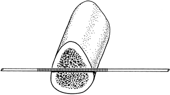 |
|
Figure 11.9. Centrally threaded Steinmann pin with the threads spanning the cortices of the bone.
|
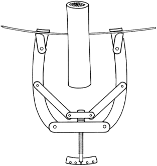
femur, the tibia (proximal or distal end), or the os calcis. Traction
is best applied with the use of a Böhler stirrup or bow, which fits
over the ends of the pin. The design of the clamps holding the pin is
such that movement of the stirrup does not rotate the Steinmann pin and
cause it to loosen, because the bearings on the stirrup clamps allow
free rotary movement on the pin (Fig. 11.10). See Chapter 10 for technical details.
 |
|
Figure 11.10.
Böhler traction stirrup showing its fixation to the Steinmann pin while allowing rotary movements of the stirrup around the pin. |
pins into each end of a long bone fracture and then, after reduction,
incorporation of the pins into a cast (i.e., “pins-and-plaster”
technique) was used for many years. The stability of this construct is
not very satisfactory, however. There is always a tendency for the
plaster cast to loosen and, by its weight transmitted to the pins,
provoke pin loosening and pin tract reactions (see Chapter 10).
The use of pins-and-plaster techniques has largely been replaced by the
more efficient and advantageous external skeletal fixators, which are
discussed later in this chapter and in the various sections on
fractures.
and T-handle or hand drill into soft bone, but this technique tends to
lead to inaccurate pin placement. Particularly in hard cortical bone,
such as the upper end of the tibia in young people, free-hand
introduction of a Steinmann pin is very difficult and inaccurate; in
this situation, always predrill the pin tract with a drill bit having a
cutting tip that does not generate heat. The use of a power drill to
insert the Steinmann pin directly into dense bone may generate
sufficient heat to cause bone necrosis; infection frequently ensues
with loss of fixation and development of a ring sequestrum and
osteomyelitis.
are used in the external fixation of bones, are discussed later in this chapter.
-
Make an initial skin stab incision with its long axis in the line of subsequent traction pull.
-
Use a soft-tissue guide over the appropriate drill bit and drill a pin tract at right angles to the subsequent traction pull.
-
Then introduce the Steinmann pin by hand
into the bone with a Jacobs chuck and T-handle, making the skin
incision at the exit site of the pin tip. Little heat is generated with
a sharp drill, so bone necrosis does not occur; infection, loosening,
and sequestrum formation are much less likely, and greater accuracy of
pin placement is achieved. -
Apply a Böhler traction bow or stirrup to the pin and apply traction.
-
Release any skin compression developed on
applying the traction by incising the skin next to the pin; this is
necessary to prevent skin necrosis and subsequent infection. Keeping a
snug fit of the skin on the pin in the absence of tension on the skin
minimizes motion of the skin on the pin and helps to prevent infection,
so close any excessive incision. Keep the pin sites dressed in a
sterile fashion and cap the pointed tip of the Steinmann pin to prevent
injuries.
understanding of active and passive muscle forces allows the use of a
minimal amount of fixation material to obtain excellent fracture
stability and immediate functional movements of the contiguous joints.
The principle of the tension band wire is that tensile fracture
distracting forces, which the wire can easily absorb, are converted
into stabilizing compression forces passing through the bone. It is
essential that the cortex distant from the tension band side be strong
enough to bear the applied compressive load. Loss of bone stock or poor
bone quality will allow development of bending stresses, leading to
wire fatigue and failure of the fixation. Tightening of the tension
band wire produces static compression, particularly through the cortex
under the wire. On active joint flexion, dynamic compression results
across the whole of the fracture surface.
considerable ductility, combined with a high yield point and ultimate
tensile strength. The wire is usually available in diameters from 0.4
to 1.5 mm made from type 316 stainless steel or Vitallium. The modulus
of elasticity of Vitallium is higher than that of steel and for the
same strain should support higher loads than stainless steel of equal
diameter. Wire is weakened by cold working (e.g., kinking, bending,
twisting), so care must be taken to avoid damage during implantation.
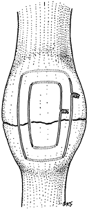
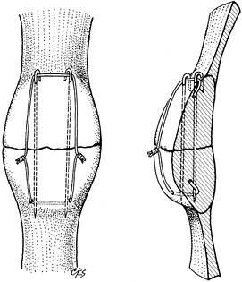
wire alone, as in a transverse fracture of the patella in which an
irregular fracture line allows perfect reduction by interdigitation of
the fracture surfaces (Fig. 11.11). In most
situations, however, axial rotational stability cannot be obtained
without the addition of two parallel, longitudinally placed K-wires (Fig. 11.12).
In comminuted fractures, the K-wires also assist in providing some
interfragmentary stability, which is completed by the tension band
wire. The K-wires must be inserted in a parallel fashion. Crossed wires
provide much less rotational stability and interfere with
interfragmental compression. The K-wires also provide anchorage points
around which the tension band wire can be placed.
 |
|
Figure 11.11. Transverse patellar fracture stabilized by two tension band wires.
|
 |
|
Figure 11.12. Transverse patellar fracture stabilized with two parallel, longitudinally placed K-wires and tension band wire.
|
 |
|
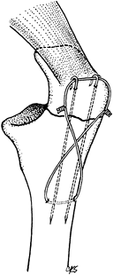
Figure 11.13. Transverse olecranon fracture stabilized with two parallel, longitudinally placed K-wires and a figure-eight tension band wire.
|
-
After exposure of the fracture, place a 2
mm drill hole 2–3 cm distal to the fracture in a transverse fashion,
passing just ventral to the dorsal cortex (Fig. 11.13). Then pass a 1.0 mm (18-gauge) or a 1.2 mm (16-gauge)
P.319
diameter wire through the hole and displace the wire distally out of the proximal fracture field. -
To control fragment rotation, insert two
1.6 mm diameter K-wires parallel from the tip of the olecranon into the
distal fragment (Fig. 11.13). This can be
achieved using a 2 mm triple guide, or the wires can be inserted
retrograde from the fracture site to exit the tip of the olecranon. -
After fracture reduction, advance the 2
K-wires 3 or 4 cm into the distal fragment. Alternatively, the wires
can be inserted in an antegrade manner from the tip of the olecranon
before fracture reduction, allowing their accurate placement within the
medullary canal to be confirmed before reduction and driving of the
wires across the fracture site. With more experience, after anatomic
reduction of the fracture, the K-wires can be inserted from the tip of
the olecranon across the fracture site and into the distal fragment.
More secure fixation is obtained by drilling the wires through the
anterior cortex rather than placing them in the medullary canal. -
Place the ductile wire around the
protruding proximal tips of the K-wires in a figure-eight fashion. Be
certain that they are against bone. Throw a simple loop in the midpoint
of one limb of the figure eight, and complete the opposite limb by
twisting the two ends of the wire (Fig. 11.13).
Twisting the loop and two ends of the wire alternately allows
well-controlled and equal tension in the whole figure-eight wire.
Achieve wire tightening with bullet-nosed pliers, being careful that
the wire ends are arranged in a helical fashion one around the other
and that the pliers do not score the tensed wire. Shorten the twisted
wire ends and the twisted loop to about three helical twists, and bend
the wire ends away from the subcutaneous region to lie alongside the
bone. Bend the proximal protruding K-wires twice, shorten them
appropriately, and then impact them, like a staple, into the bony tip
of the olecranon (Fig. 11.13); this prevents
migration of the pins. Even with some comminution of the olecranon, the
tension band wire technique can still be used after reduction and
fixation of the minor fracture fragments with lag screws; thus,
excision of the olecranon can usually be avoided. -
Commence immediate postoperative active
flexion exercises for the elbow; extension exercises should proceed
with more care because the bone–fixation complex is less stable in
extension. If the proximal ends of the K-wires are not sufficiently
impacted into bone, they can back out and protrude under and even
through the skin (68). Another occasional
complication is for the tension band wire to cut out of the distal
fragment if it has not been inserted deeply enough below the dorsal
cortical surface. After fracture union, the tension band wires tend to
be uncomfortable. Removal is often necessary. The tension band wiring
technique can similarly be employed for transverse and comminuted
patellar fractures, fractures of the femoral greater trochanter,
fractures of the malleoli (particularly where small or osteoporotic
fragments are involved), and fractures of the distal end of the
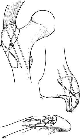
clavicle (Fig. 11.12 and Fig. 11.14).![]() Figure 11.14.
Figure 11.14.
Tension band wiring techniques employed to stabilize greater
trochanteric, comminuted medial malleolar, and distal clavicular
fractures.
provisional fixation of long-bone fractures or for definitive fixation,
usually in combination with other fixation devices.
that described for use in tension band wiring. Wire diameters of 0.8 to
1.25 mm are commonly used, and the strength varies directly with the
square of the diameter. Two wires may be twisted to form a double
strand, which may have greater flexibility than a single wire and is
less likely to slip on the bone. Some cerclage wires are manufactured
with a loop in one end, so that after passage around the bone the other
end can be threaded through the loop and kinked backward to quickly
achieve temporary fixation (Fig. 11.15).
Regular wire can be tightened around the bone by twisting the two ends
one around the other in a helical fashion with the aid of bullet-nosed
pliers or one of the many available wire tighteners, while maintaining
adequate tension on the wire (Fig. 11.15). A
minimum of two full twists is necessary for maximum strength with 1.0
or 1.2 mm diameter wire, and the pitch of the twists should be as high
as possible (50).
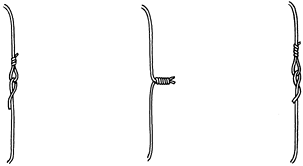 |
|
Figure 11.15. Methods of joining ends of wire. A: One end of the wire is passed through a loop in the other end and kinked backward for temporary fixation. B: Helical twisting at a high pitch at the ends of the wire for temporary or definitive fixation. C: Technique like (A) but with one end of the wire passed under itself and against the underlying bone.
|
than the yield strength of the wire is satisfactory. For definitive
cerclage wiring, it has been suggested that tying a formal square knot
between the wire ends produces a fixation least likely to disengage (50).
After the first throw of the knot and subsequent tightening, however,
it is very difficult to maintain wire tension during the second throw
of the knot (47,86).
Although it is unlikely to completely unfold, with time the knot will
commonly relax and precipitate failure of fixation. Knots therefore are
suitable only for wire securing soft tissues. Helical twisting of the
wire ends is easily applied, maintains the initial fixation tension,
and will untwist only at tension loads beyond an acceptable limit.
Anchoring the twisted wire tips by folding them down into a predrilled
hole has been shown to produce the least slippage compared with other
methods (48). The AO loop with bending of the
free end under the wire also produces a satisfactory fixation strength,
but the passing of the free end of the wire between bone and the
tightly opposed cerclage can be very difficult (Fig. 11.15) (50,111).
use by yielding, elongating, or fatiguing due to repetitive loading.
This is especially true if the wire has in any way been scored before
or during application (29).
condemned as interfering with the periosteal circulation and thus
producing bone necrosis. However, it has clearly been shown that the
bone cortex receives most of its vascular supply in a centrifugal
fashion from the medullary cavity, and even complete loss of periosteal
blood supply may
not
lead to cortical necrosis. The periosteal vessels also tend to pass
vertically into the cortex and not run along the cortical surface.
Therefore, thin cerclage wires placed circumferentially at intervals
are unlikely to severely damage periosteal blood supply in mature or
immature bone (46,85,112).
This contrasts with previously used wide Parham bands, which did
eliminate periosteal blood supply from relatively wide segments of
underlying bone (77,85).
Recent modifications of Parham bands, as described by Partridge, are
made of nylon and have elevations on the underside of the band that
prevent wide contact and constriction on the bone by the band (78).
This modified form of cerclage fixation may be useful in situations in
which severely osteoporotic bone prevents other forms of stable
internal fixation.
control butterfly fragments in femoral shaft fractures, in which
erosion of the bands into the cortical bone has sometimes been found (54).
circumferentially around the bone in the treatment of patellar
fractures is now considered obsolete. This technique is not efficient
and permits fracture fragment separation and mobility (108). Tension band wiring techniques described in this chapter are much more applicable to the problem.
butterfly fragment is diametrically opposite the line of approach to
the bone, the judicious application of a temporary cerclage wire may
hold the butterfly fragment reduced so that lag screws may be inserted
into it (Fig. 11.16). After stable screw fixation, remove the cerclage wire.
 |
|
Figure 11.16. Temporary cerclage wiring to facilitate lag screw fixation.
|
prophylactically around the femur to prevent splitting during press-fit
insertion of an uncemented femoral prosthesis.
incisions to treat oblique or spiral diaphyseal fractures appears at
first to be attractive (24,86).
Even if stable fixation is initially obtained, however, the likelihood
of the development of fracture angulation and loss of stability is
significant because of the inevitable loading of the bone.
Supplementation with some form of external casting is required, and
this obviates early functional treatment of the limb. Stable closed
intramedullary nailing of a diaphyseal fracture usually solves the
problem more efficiently than cerclage wiring alone. However, several
cerclage wires may be used in a supplementary fashion at 1 cm intervals
along the shaft with intramedullary nailing (Fig. 11.17) or Ender rodding and as an adjunct to the Zickel nail in subtrochanteric fractures (53,73,118).
 |
|
Figure 11.17. A: AP radiograph of femoral fracture with one large, free fragment. B: AP radiograph of femoral fracture treated with intramedullary nailing and three cerclage wires.
|
-
Pass the wires at 90° to the long axis of
the bone so as not to slip longitudinally and loosen. All cerclage
wires around the bone should be placed under the same tension to
distribute the subsequent strain evenly between the wires; a wire
tightener whose tension can be calibrated is necessary. -
Use a wire passer to facilitate passage of the wire around the bone and minimize soft-tissue trauma.
-
Obtain anatomic reduction of the fracture
before wire tightening; otherwise, wire loosening in the postoperative
period is likely as settling of fracture fragments occurs. Cerclage
wiring techniques may also be used in the proximal femur where a
fracture has occurred during or after the insertion of a femoral
prosthesis. Cerclage wiring can be very effective in this situation if
care is taken to slightly notch the bone to prevent the wire from
sliding distally along the taper of the femur.
developed a cerclage system employing two different sizes of cable that
can be crimped to a grappling device. Similar devices are available
from most orthopaedic implant companies. The mechanical properties of
the multifilament cable are superior to monofilament wire in resistance
to fatigue, and the cable has a higher yielding and breaking strength.
The cable is also easy to work with because it does not have a tendency
to kink. The cable-grip system was originally developed to facilitate
reattachment of the greater trochanter in total
joint arthroplasty, but it has proven to have many applications in internal fixation (34).
popularity, and designs of external fixators have changed continuously.
A variety of reliable pin fixators are now available with different
clinical and mechanical properties (13). Ring
fixators have become accepted tools for correcting limb-length
discrepancies and malalignments, compensating for bone loss, and
correcting soft-tissue contractures (72).
Additional indications for ring fixators include severely comminuted
peri- or intraarticular fractures, particularly in osteopenic patients.
Recent efforts to make external fixators safer and more effective have
made them invaluable tools in the care of injured and deformed
patients. The devices are as reliable as plaster casts and internal
fixation, yet more versatile, and they encompass a wider range of
indications (13,14,37).
External fixators are most useful when other methods of skeletal
fixation seem too risky or when temporary fixation is required until
tenuous soft-tissue conditions have resolved and definitive internal
fixation is safer.
for pin and ring fixators, this chapter focuses on pin fixators that
predominate in the treatment of acute, traumatic, and infective
conditions. See Chapter 32 for a thorough
discussion of ring fixators. Comminuted juxtaarticular fractures,
particularly in the proximal and distal tibia and distal femur, are now
frequently managed with hybrid external fixators, putting to best use
the advantages of a ring fixator adjacent to the joint and a unilateral
half-pin fixator on the diaphysis.
confusing, closer analysis shows that each device comes with a limited
number of similar components. These can be assembled into four frame
types with distinct clinical properties and mechanical features (9,13).
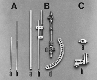
on one end and rounded or sharp tips. I prefer self-cutting and
self-tapping pins (Fig. 11.18) as they are
simple to use. Various diameters and lengths are available, from the
smallest for the digits up to the largest for the femur and pelvis.
 |
|
Figure 11.18. A: Pins. a, Half-pins; b, centrally threaded transfixion pins. B: Connecting elements. a, Simple rod; b, rod with compression and distraction capabilities; c, rod with terminal universal articulations and capability for compression, distraction, and free axial sliding; d, circular connecting element. C: Articulations. a, Simple, adjustable clamp; b, universal clamp.
|
same or in different bony fragments. Complex rods have in addition a
built-in capability to compress or distract, provide axial loading
across the fracture at specific loads and excursions, and provide
articulations for angular adjustments.
pins, two rods, or a pin and a rod. Modular articulations hold two or
more pins in one clamp, which is connected by a universal joint to a
longitudinal rod.
quantitative torque-measuring capabilities, to tighten the
articulations; hand-held devices to insert and remove pins; drill bits;
drill guides; depth gauges; pin caps; removable compression devices;
and pin cutters.
components of a device is called a fixator frame or fixation
configuration. In accordance with a frame’s space requirements, we
differentiate between unilateral and bilateral frames (11)
and multiplanar devices. Each of the former two frame types can be
applied in a one- or two-plane configuration. One-plane configurations
are less cumbersome, and two-plane configurations are more effective in
neutralizing bending and torsional moments (Fig. 11.19).
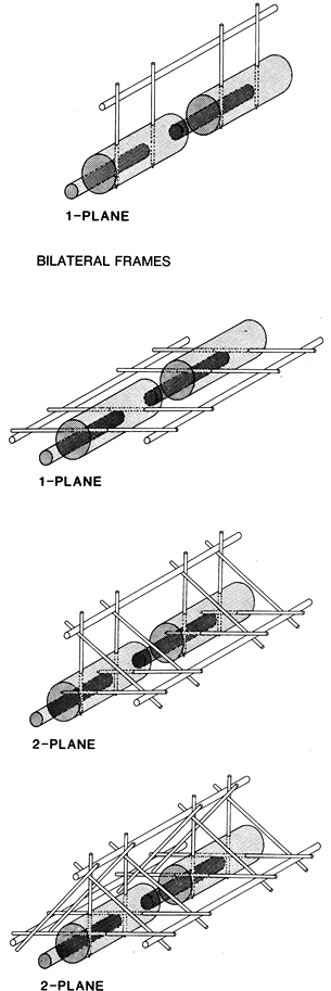 |
|
Figure 11.19.
The four basic configurations of external fixation frames. (From Behrens F, Searls K. External Fixation of the Tibia: Basic Concepts and Prospective Evaluation. J Bone Joint Surg Br 1985;68:246, with permission.) |
In the past, however, they were afflicted by a high rate of pin tract
infections, malunions, nonunions, and component failures (25,96,105).
Weight bearing was often possible only after advanced consolidation of
the fracture callus. Most of the mechanical disadvantages of these
configurations have been resolved through the introduction of stiffer
components or a combination of stiffer
components and mechanical optimization of frame designs (10,37,41).
Two-plane unilateral frames (e.g., Delta frame, tent frame, triangular
frame) can provide increased frame stiffness even with the use of
relatively weak components, but they are more cumbersome and may
interfere with wound access and secondary operative procedures (9,11).
frame, bilateral frame) were frequently used during the 1970s, when it
was felt that the transfixion pins and the bilateral longitudinal
support system would render them considerably stiffer than the
traditional unilateral designs (56,105). Subsequent mechanical studies showed that these frames are rather weak in resisting sagittal bending moments (12,19).
The insertion of multiple closely spaced transfixion pins caused
compartment syndromes, neurovascular injuries, and impairment of
musculotendinous units with resulting joint stiffness (11).
One-plane bilateral frames are therefore considered unsafe in most
locations and have been largely abandoned. The stiffest configurations,
two-frame bilateral frames, have been advocated for the management of
infected and unstable fractures, in particular pylon fractures of the
ankle, or to provide optimal conditions for bone healing. Although
mechanically better balanced than one-plane bilateral frames, they are
not commonly used today; new unilateral fixators work as well and are
not afflicted with all the disadvantages and complications caused by
transfixion pins and bilateral rods.
The frame must minimize obstruction to other operative procedures, be
adaptable to a wide variety of injury patterns, and be stiff enough to
maintain alignment under various loading conditions. Its use should
facilitate full weight bearing yet produce a low rate of serious
complications. These goals are best achieved by adhering to three basic
principles (9,11,14).
In decreasing order of importance, these principles demand that an
applied frame minimize the risk of injury to the vital limb anatomy,
provide ready access for wound debridement and secondary procedures,
and meet the mechanical demands of the patient and the injury.
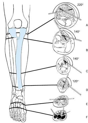
which pins can be safely inserted is primarily determined by the
location of the main vessels, nerves, and musculotendinous units. Of
the two limb segments that make up the lower extremity, the distal
segment is much better suited for the application of an external
fixator, because the principal bone lies eccentrically and the pins can
be inserted through a subcutaneous bony corridor (14,42).
show that in the proximal third of the tibia, pin placement is safe
within an arc of 220°, which extends from the posteromedial border of
the tibial plateau to the proximal tibiofibular joint (42).
Excluded is a small rectangular area overlying the patellar tendon.
This safe anteromedial corridor decreases to 140° just below the tibial
tubercle and to 120° at the ankle joint. Therefore, half-pins are
safest distal to the tibial tubercle. Full transverse pins tie down the
muscles of the anterior compartment; in certain locations neurovascular
structures are threatened by injury
from a pin, so their use should be minimized and their insertion should be done judiciously.
 |
|
Figure 11.20. The “safe corridor” for pin insertion in the lower leg. A: Proximal to the tibial tubercle, pins can be safely inserted within an arc of 220°. B: Just below the tibial tubercle, the safe arc decreases to 140°. C:
In the distal third of the leg, the safe arc remains 140°, but the anterior tibial vessels and deep peroneal nerves become vulnerable as they cross the lateral tibial cortex. D: Above the ankle joint, the safe arc is 120°. E,F: Pins in the tarsal or metatarsal bones may be used to splint the ankle joint if neurologic or soft-tissue injuries prevent the application of an external support. (From Behrens F, Searls K. External Fixation of the Tibia: Basic Concepts and Prospective Evaluation. J Bone Joint Surg Br 1985;68:246, with permission.) |
attention. Proximally, a pin can pierce the protective posterior muscle
layer and injure the posterior neurovascular structures. This is
prevented if the pin exit area is limited to the medial third of the
posterior tibial cortex. In the distal third, the anterior tibial
vessels are vulnerable along the lateral tibial cortex, which therefore
should be avoided. Whenever possible, pin placement should be limited
to areas where the tibia lies subcutaneously.
femur is circumferentially covered with soft tissues. There is no ideal
corridor available as all pins pierce the thigh musculature before they
are seated in the bone (3). Preferred pin
placement is from the lateral side, just anterior to the intermuscular
septum. Half-pins are essential because they transfix only the vastus
lateralis. Sometimes the pins can be inserted anterior to the lateral
intermuscular septum and posterior to the vastus lateralis, but they
still limit the excursion of the iliotibial band and thus restrict knee
motion while the fixator is in place (3,9).
Medial-pin exit sites that are between the midfemur and the distal
fifth are in a danger zone, because in this region the superficial
femoral vessels and the saphenous nerve are tightly held in the
adductor canal and are vulnerable to pin injury. If pins in these
locations are essential, place them using open technique and avoiding
the neurovascular bundles. These same considerations apply to the upper
extremity. Only the subcutaneous borders of the long bones are
reasonably safe, but even there tendons and cutaneous nerves are still
at risk of injury. In general, place upper-extremity fixation pins with
open technique.
of safe frame types to one- or two-plane unilateral configurations.
Within the safe soft-tissue corridor, the best pin location, frame
geometry, and frame placement are determined by the size and severity
of soft-tissue lesions, and by the comminution and stability of the
bone injury. Adapt each frame to the injury at hand to permit the best
possible wound access for initial care, repeated debridements, and
secondary soft-tissue procedures such as the transfer of local and
distant soft-tissue flaps and the placement of bone grafts. Within the
safe corridor, place pins and frames away from the injured area and the
principal access routes. If an injury involves mainly the medial side
of the leg, apply the frame anteriorly or anterolaterally; a lateral
injury may call for a medial or anteromedial frame (Fig. 11.21).
 |
|
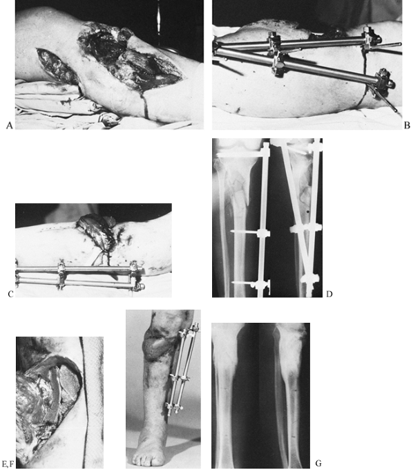
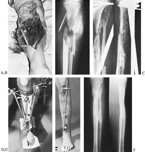
Figure 11.21. A gunshot wound involving the lateral aspect of the proximal tibia with severe loss of soft tissue and bone. A: Initial appearance from the lateral side. B: Stabilization by an external fixator placed on the medial side. C:
The soft-tissue defect covered by a lateral gastrocnemius flap; there is no interference from the fixator frame. A split-skin graft was used to cover the muscle flap. D: Radiographs at this stage. E: Elevation of the healed gastrocnemius flap to allow the skeletal defect to be bone grafted. F: At 5 months, the fracture has healed, and the patient has borne full weight for 4 weeks. G: Radiographs 1 year after the injury. (From Behrens F, Searls K. External Fixation of the Tibia: Basic Concepts and Prospective Evaluation. J Bone Joint Surg Br 1985;68:246, with permission.) |
frame should control the prevailing forces and moments at the fracture
site. Information based on the size and weight of the principal lower
extremity segments and the distribution of the muscles surrounding the
femur and tibia indicate that, in the supine position, sagittal bending
moments are two to five times larger than the moments acting in the
frontal plane. After a patient is weight bearing, compressive loads and
torsional moments around the longitudinal axis gain in importance (11).
However, there is little change in the ratio of
anteroposterior-to-frontal bending moments. This suggests that
regardless of other mechanical properties, a fixator frame in the lower
extremity should be about two to five times stiffer in the sagittal
than in the frontal plane (12). For tibial
fixators, this stiffness ratio is most easily achieved if the principal
pin plane is oriented in an anteroposterior (AP) direction. Although
clinically appropriate, lateral femoral frames are not ideal
mechanically because they are relatively inefficient in resisting
fragment motion in the sagittal plane. To
counteract
this tendency, spread the pins in each principal bony fragment as far
apart as possible. Use stiff longitudinal rods and double-stack them if
necessary (3).
geometry are other factors that influence the application of a
mechanically effective frame. Assuming that stainless steel components
are used, the pins should have a diameter of at least 5 mm, and the
longitudinal rods should have a diameter of 8 mm or more. The
articulations must not slip within the range of clinically applied
torques. Experimental work has shown that the following methods
increase frame stiffness in one or more loading modes (10,12):
-
Increasing the pin spread within each main bony fragment (14)
-
Reducing the distance between the bone and the longitudinal rods (13)
-
Attaching a second longitudinal rod to the same pin plane (10)
-
Erecting a second half-frame at an angle to the first (i.e., creating a two-plane unilateral frame)
accommodate most tibial and femoral injury patterns without the need
for bilateral frames. Unilateral frames suffice for most
upper-extremity injuries.
Although much of this planning process occurs before the fixator is
applied, it must anticipate the most likely time course of healing and
the principal variations and potential complications that might be
encountered.
premorbid condition, socioeconomic circumstances, and the cause,
severity, and extent of the injuries. Determine whether external
fixation is the best method for treating the patient’s injuries, what
is the best device and in what configuration, whether the fixator will
be used alone or in conjunction with internal fixation (Fig. 11.22),
what equipment is available, and what surgical skills are needed.
Determine also if the full frame should be applied immediately or
completed at a later time, and whether the fixator will remain in place
until the fracture is healed or will be replaced with a cast or
internal fixation as soon as the soft-tissue conditions permit (14).
 |
|
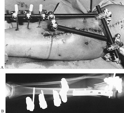
Figure 11.22. A:
Comminuted proximal tibial fracture in an elderly patient, showing a combination of external and internal fixation to stabilize the comminuted periarticular fracture pattern in an osteopenic patient. B: Radiotranslucent carbon fiber rods facilitate assessment of the fracture site and proper timing of secondary intervention, yet provide sufficient stability to allow for soft-tissue consolidation. |
designs are preferred for patients who are heavy or who have an
unstable fracture pattern. For the younger child, a wrist or upper
extremity device may be sufficient. When rapid application is essential
or proper radiographic control unavailable, fixators with full
universal joints at both ends are ideal, because they facilitate
alignment and length adjustments at a later time (88,96).
repeated assessment of healing, devices composed of radiolucent carbon
fiber components are advantageous.
a particular fixator frame depend on the extent of the soft-tissue
injury within the safe corridor, the stability and location of the
fracture, the size of the patient, the presence
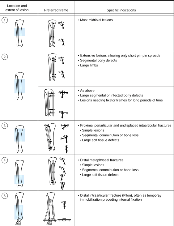
of associated lesions, the size of the fixator components, and the designs of the fixator articulations (14).
spread and provide moderately stiff components, 80% to 90% of the
applied frames are of a one-plane unilateral design (13).
For devices that provide universal articulations but lack the
mechanical advantage of maximal pin spread (e.g., Hoffmann apparatus,
Orthofix), the risk of slippage at the articulations is considerable.
With these fixators, take care to use undamaged functioning
articulations and possibly double-stacked one- or two-plane unilateral
frames (96). These configurations are preferred for fractures with segmental bone loss or extensive comminution (Fig. 11.23, item 2, lower drawing). One-plane frames with double rods (Fig. 11.19, upper drawing) have a rigidity pattern similar to that of two-plane unilateral frames,
but they are less cumbersome and allow better wound access (10).
Due to their greater rotational rigidity, two-plane unilateral frames
may be still preferable for the management of infected nonunions and
lesions that are accompanied by substantial bone loss.
 |
|
Figure 11.23.
The recommended configuration of fixator frames for different bone and soft-tissue injuries. The location and extent of the lesion is indicated, on the left, by the crosshatched area. The preferred frame is shown, with solid bars representing the pins; on the right are the indications for the use of the configuration. (From Behrens F, Searls K. External Fixation of the Tibia: Basic Concepts and Prospective Evaluation. J Bone Joint Surg Br 1985;68:246, with permission.) |
stabilizing comminuted proximal and distal periarticular fractures,
which often provide only short metaphyseal or epiphyseal fragments for
pin insertion. With simple frame modifications (Fig. 11.21B; Fig. 11.23, items 3 and 4),
however, these fractures are easily managed. Proximally, where the safe
corridor opens wide, subchondral pin placement affords anchorage for
two or more half or full pins (Fig. 11.21B, Fig. 11.21C and Fig. 11.24D). Over two or more longitudinal
rods, these pins are then rigidly connected to several distal pins,
which in the tibia are placed close to the sagittal plane. After the
application of these frames, the knee is moved through a full range of
motion to ensure free mobility of joint capsule, pes anserinus, and
iliotibial band. Distal tibial fragments as short as 2 or 3 cm long can
be stabilized by inserting two or more pins on either side of a
longitudinal rod (Fig. 11.23, item 4).
For the immobilization of distal intraarticular fractures, a talar or
calcaneal pin is connected with two rods to two or more anterior
half-pins in the proximal tibia (Fig. 11.23, item 5). Hybrid frames work well and to some extent have replaced these frames. These are presented in more detail in Chapter 23 and Chapter 25.
 |
|
Figure 11.24. A grade 3 open tibial fracture with bone loss in a patient with other open fractures. A: Clinical appearance on admission. B: Radiographic appearance on admission. C,D:
Stabilization of the fracture with two-plane bilateral pin configuration proximally and three anterior pins distally. Bone graft had been delayed for 3 months because of adult respiratory distress syndrome. E: At 8 months, after the patient had started full weight bearing, the frame was gradually reduced. As a last step before removal, the proximal pin was loosened. F: Radiographs 1 year after injury. |
the management of type II or IIIA open tibial fractures with two or
three comminuted fragments. After anatomic reduction and
interfragmental compression with screws, a relatively rigid external
frame is applied instead of a neutralization plate. This approach has
been quite successful in metaphyseal fractures, which generally heal
within 2 to 3 months. In the diaphysis, however, high complication
rates, mainly in the form of refractures, have been common. This is not
surprising, because in cases of avascular diaphyseal fragments bony
union is often delayed for more than a year. Additional detail on this
issue is provided in Chapter 24.
-
Drape the limb to keep the injury zone
and the adjacent joints accessible in the operating field. Avoid
adhesive plastic drapes where pins will be inserted, as they tend to
wind up on drill points and pins and may be inadvertently transported
deep into the wound. An image intensifier helps to assess proper pin
location, pin depth, and fragment alignment, and it is particularly
valuable in dealing with closed fractures that do not allow direct
manipulation of the fracture fragments.
-
Make a skin incision just large enough to
accommodate the drill point and pin sleeves to be used. Most
manufacturers provide matched protective sleeves for drilling, depth
measurement, and pin placement. -
In deeper bones, incise the deep fascia (a small x
often facilitates guide sleeve placement); separate muscle fibers with
a Metzenbaum scissors or a small elevator and elevate the periosteum at
the pin site. Many half-pins are now available with specially designed
tips that are self-cutting and self-tapping and have flutes to deliver
bone fragments. To avoid overheating, bone necrosis, and pin breakage,
never insert these with power but rather with hand drills provided by
the manufacturer.
-
Insert the protective sleeves down to the bone.
-
Gently impact the teeth of the sleeve or trochar into the bone, if called for by the manufacturer.
-
Drill the initial hole with the size
called for by the manufacturer for the pin diameter to be used. Use
power, cool the drill, and avoid overheating the bone. -
Usually one drill size suffices. In some
cases, the near cortex must be drilled with a larger diameter to
accommodate a larger smooth shank on the pin. -
Select the appropriate pin and the thread length: in some systems, a depth gauge is required, or the drill may be calibrated.
-
Insert the pin until at least one full
thread penetrates through the opposite cortex. Carefully monitor this
with the fluoroscope, as in some systems the pin cannot be reversed
without loosening. -
Many half-pin systems allow selection of
a total thread length that is 5 mm less than the overall diameter of
the bone at the site where the pin is inserted. This permits the wider
nonthreaded shaft of the pin to fit tightly into the proximal drill
hole and places a smooth shank at the level of skin. This reduces skin
irritation and doubles the bending stiffness of the pin (Fig. 11.25).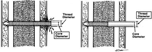 Figure 11.25. Seating of half-pins. A:
Threaded pin portion protrudes beyond the skin. This tends to cause
skin irritation and pin-tract infection. Pin stiffness is determined by
the core diameter. B: Threaded pin portion
is limited to the distal cortex. The smooth shaft rarely irritates the
skin. Pin stiffness is determined by the larger thread diameter. (From
Behrens F. General Theory and Principles of External Fixation. Clin Orthop 1989;241:15, with permission.) -
Once the entire frame has been assembled
and the fracture reduced, check the skin around each pin to be certain
that tension on one side of the pin is not present. This is indicated
by gathering of the skin. If there is tension, incise skin where it is
gathered until it lies tensionless around the pin. -
Differential motion of skin on the pin
can result in bacterial contamination of deeper tissues; therefore,
gently close any excessive incision about the pin with a fine nylon
suture that can be removed when the skin is healed.
type of fixator used. Many frames allow independent pin insertion, in
which case be certain that the limb or the fracture is aligned and
insert the next pin most distant from the initial pin. The initial pin
should have been the most extreme pin at the other end of the bone.
Insert the second pin using either a template guide or the preassembled
fixator as a guide.
proximal and distal fragments. With these fixators, independent
arrangement of the pins anywhere along a fixator bar, such as in the
unilateral frame, is not possible as the pins are inserted through a
clamp or ring that holds the cluster of pins in one fragment in a
more-or-less fixed arrangement relative to the others. The exceptions
are Ilizarov type ring fixators, where pins can be placed anywhere
along the 360° arc of the ring, and pin clamps that allow a limited
range of placing the pins longitudinally on the bone. With these
fixators, maintenance of overall alignment of the limb is less crucial,
as universal adjustment clamps permit reduction of the fracture after
the fixator has been applied; however, each fixator has a limited range
of adjustment. It is possible to apply pin clusters so out of alignment
with each other that reduction cannot be achieved. Therefore, it is
always prudent to maintain general overall alignment of the limb,
particularly rotation, as any type of fixator is applied. The following
steps describe the technique for a typical fixator of this type.
-
Using the manufacturer’s guide or the
fixator itself, insert the pins in one fragment and then the other. A
wide spread of the pins within the range allowed by the clamp increases
stability. Always apply the two outer pins on a given clamp first, to
be certain that all pins will be anchored in bone. -
Now reduce the fracture; with the
universal joints loose, obtain anatomic reduction. Tighten the
universal joints or adjustments once reduction is achieved. -
If fracture-fragment alignment is not
satisfactory on subsequent fluoroscopic examination or x-rays, loosen
the universal joints and repeat the reduction maneuver.
-
Insert one pin into each main fragment,
generally starting with the pins close to the joints (i.e., farthest
from the fracture). Maintain gross alignment of the limb (14). -
Reduce the fracture. Apply adjustable
clamps to each pin and connect them by a longitudinal rod. Then
manually reduce the fragments and tighten the two clamps to achieve
temporary reduction. Proper rotational alignment is crucial (13). -
Insert the remaining pins (10).
-
Adjust the fixator. Adjustments in the
plane of pin insertion are easily achieved by loosening the pins. For
angular adjustments in another plane, replace the longitudinal rod by
two shorter ones that are connected over a central universal joint. For
the correction of significant rotational malalignment, all pins except
one in each fragment must be exchanged.
simple transverse or interdigitating fractures, axial compression of
the fracture site provides additional stability. When axial compression
is attempted with unilateral frames, the fracture fragments have a
tendency to angulate away from the longitudinal rods. It is
advantageous to start with the fracture fragments angled toward the
rod(s). With increasing compression, the fracture fragments tend to
straighten into anatomic alignment.
comparing the injured to the opposite limb, if it is uninvolved; for
assessment of alignment, however, obtain AP and lateral radiographs
that include the joints above and below.
extremity, for example in balanced suspension with the calf muscles
supported with a sling (Fig. 11.26). Support
the ankle joint in 5° to 10° of dorsiflexion with a prefabricated
splint. If the patient has sustained a severe soft-tissue injury (in
particular, compartment syndrome requiring fasciotomy, or palsy or
paresis of the common peroneal or posterior tibial nerves) or bony
injury distal to the ankle joint, replace the ankle splint with a
transtarsal pin (Fig. 11.20E) or two metatarsal pins that are connected to the external fixator frame (Fig. 11.20F).
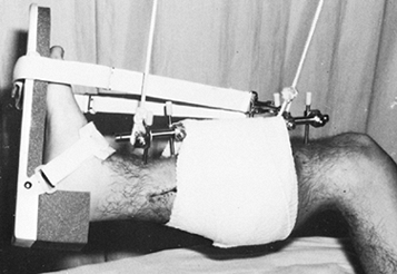 |
|
Figure 11.26.
The early postoperative management of an open tibial fracture. The limb is suspended, the calf is supported, and the ankle joint is splinted in 5° to 10° of dorsiflexion. |
passive, active-assisted, and active range of motion exercises of knee
and ankle joints. Follow with isometric muscle strengthening exercises
across both joints and mobilization with crutches or a walker. As soon
as tolerated, encourage the patient to partially bear weight on the
injured extremity, progressing to full weight bearing as the fracture
consolidates, if the fracture type and external fixator permit. If this
course is conscientiously followed, approximately 70% of all patients
with tibial fractures can advance to full, unsupported weight bearing
before the fixator is removed or replaced by a different method of
immobilization. Weight bearing has little to do with pin tract
infection or pin loosening. Patients with segmental bony defects must
be limited to bearing with only the weight of the limb.
debridements, or additional soft-tissue or bony reconstructive
procedures, the limb will generally be encased in a bulky postoperative
dressing, which precludes access to the pin sites. Because the patient
returns often to the operating room for wound debridement and
subsequent reconstruction, there is no necessity for pin care by the
nursing staff on the ward. In fact, exposing an open fracture wound on
the ward unnecessarily invites contamination with nosocomial organisms.
When the wound has stabilized and repeat operations are no longer
necessary or are infrequent, it is appropriate for the nursing staff to
begin pin care, particularly since the patient must be educated in this
important aspect of care of the external fixator in an outpatient
setting. Unless the patient is hospitalized for a prolonged period of
time and is nonambulatory, pin care in the hospital differs little from
what I prefer to have patients do at home. There is little in the
literature to prove that one pin-care regimen is superior to another (98).
I have found the following program to be effective and simple for
nursing staff and patient. Using this regimen, I have had external
fixator pins located in cortical bone in place as long as 1 year with
no complications.
-
In the hospital setting, because the soft
tissues are still edematous, serum and hematoma oozes from the pin
sites and dries as a crust around the pins. This can be a source of
bacterial colonization and skin irritation. Once a day, the nursing
staff should expose the entire external fixator and all of the pin
sites, and wipe down the pins and frame. -
The dried exudate can be removed by any
method that is gentle, comfortable for the patient, and effective.
Cleaning with a 50% hydrogen peroxide solution, or simply washing the
pin sites with sterile gauze and soapy water are equally effective.
(Although many surgeons apply antibiotic or antiseptic ointment to the
pin sites, I have not found these to be of any value, and this risks
sensitizing the patient to the material used.) -
Dress the pin sites with a 2×2 or 4×4
gauze cut to fit snugly around the pin. (There are commercial sponges
available for this purpose, but I have found these to be less effective
than simple gauze bandages.) Wrap these into place to stabilize the
skin and prevent vertical motion of the skin on the pin. This helps
reduce bacterial contamination of the pin site caused by movement of
the skin along the pin, and it makes the patient more comfortable. Once
bulky dressings are no longer needed for the wound, these small gauze
bandages can be held in place by plastic clips placed on wires or
half-pins and slid down against the dressing to stabilize the skin.
These were an innovation of Ilizarov and have proven to be very useful.
simple for the patient and provide the easiest method for pin-site and
frame care. As soon as the wound allows, have the patient take a daily
shower, thoroughly scrubbing the external fixation frame and all of the
pins and wires with ordinary soap and water (avoid strong soaps and
those heavily perfumed) using a clean, fresh washcloth. Removal of
tough crust is facilitated by a soft surgical brush and a child’s
toothbrush. After the shower, the patient should dry the apparatus and
pin area with a freshly laundered towel different from the one used for
the rest of the body, and dress the pin sites as described above. For
the second pin-care episode each day, it is necessary only to clean the
pin sites themselves using similar techniques.
or another in most patients, but, if good technique is used, pin-tract
infection should be uncommon (this is discussed below in the Pitfalls
and Complications section).
in particular how to keep the frame and pin clamps tight. If they are
incapable of understanding, or of maintaining the frame, a relative or
caregiver who will take this responsibility must be involved. Provide
the patient with a wrench, or other appropriate tools, so that the
components of the frame can be checked at least weekly to be certain
that they remain tight.
evident that good care is being taken of the pin sites and frame,
reliable patients may be able to go up to 6 weeks between follow-up
visits. Less reliable patients may need to be seen by the surgeon
weekly, and they may need frequent visits by a home health nurse to do
pin-site and frame care.
fixation are of such severity that they will not heal readily without
additional biologic or mechanical measures.
with adequate soft tissue, in particular muscle, which is a source of
neovascularization (116). If coverage is not
possible locally, free muscle or composite flaps should be placed
early, because this tends to prevent the development of local wound
colonization and subsequent osteomyelitis. This is a prerequisite for
the success of later bone reconstructive procedures (88,105) (see Chapter 8 on soft-tissue management and Chapter 12 on open fractures for more detail).
need bone grafts to get the fracture to unite. When dealing with a
Gustilo type IIIA or lower grade clean open wound that allows local
closure after appropriate debridement, I may place an autogenous
cancellous bone graft at the time of soft-tissue closure. After massive
wound contamination, infection, or delayed closure with a flap, as in
type IIIB or IIIC open fractures, wait until the soft tissues are fully
recovered and there is no evidence of infection. This often requires 6
or more weeks. Reckling and Waters (83) place a
cancellous or corticocancellous bone graft, often in conjunction with
osteoperiosteal elevation through an anterior or medial incision. At
the University of California, Davis, Trauma Center, we prefer the
posterolateral approach applying a large cancellous autologous iliac
graft, and we usually perform a tibiofibular synostosis (see Chapter 26 and Chapter 31).
a patellar tendon-bearing or long-leg cast as soon as soft-tissue
coverage has been obtained (56,96).
This is often successful in patients with stable fractures. However,
unstable fractures and even stable fracture patterns often angulate
after fixator removal, even if immobilized in a long-leg cast. I prefer
to hold these fractures in the external fixator until they are healed.
After advancing the patient to full, unsupported weight bearing,
gradually dismantle the more complex configurations (e.g., two-plane
unilateral, one-plane unilateral with double rods) to one-plane
configurations with a single anterior or anteromedial rod (Fig. 11.24).
Then, sequentially loosen the pin clamps, starting with the pins
closest to the fracture site, until the load is held only by the most
proximal and most distal pins.
or distal main fragment. This permits free axial loading while
preserving angular and rotatory alignment (13). Although
attractive and logical, there is no proof that this approach leads to
an increased rate of fracture healing. Easier to use are tube-type and
other fixators that can be dynamized, some with very specific control
over the excursion and amount of loading.
This is achieved with the help of a pneumatic actuator temporarily
connected to the fixator. The actuator induces a loading regimen of 1
mm displacement at 0.5 Hz for 30 minutes each day. With this approach,
a 20% reduction in the average healing time was achieved in a
controlled trial of complex tibial fractures (59).
fracture often is best handled by replacing the external fixator with
an intramedullary rod or a plate. Internal fixation following removal
of external fixator pins where infection has occurred, particularly
osteomyelitis, is generally contraindicated until the infection has
been eradicated. Although there is little information about results and
complications after plating, indiscriminate secondary intramedullary
nailing has been shown to have a high infection rate (70).
However, secondary nailing can be performed with only a slightly
increased infection rate if the procedure is carried out very early or
within 4–6 weeks of fixator application (15).
Even with these restricted indications, it is safest to place the limb
in a cast for 2–4 weeks before proceeding with intramedullary nailing
to allow the pin tracks to heal. Unless extraordinary circumstances
prevail, avoid intramedullary nailing after local soft-tissue or bony
infection or in a patient who once had a pin tract infection, because
the sequelae of an infected medullary canal can be disastrous.
particularly when associated with weight bearing or exercise, nearly
always have a loose pin or wire. Once soft tissues have healed, the
patient has recovered from the initial trauma and/or surgery, and the
fracture site has begun to consolidate, the average patient should be
quite comfortable in the fixator, requiring minimal across-the-counter
pain medication. Pain is a greater problem when a vigorous
rehabilitation program is in progress and the patient has pins through
large soft-tissue envelopes such as in the thigh, where muscles,
tendons, and fascia are constantly being tethered by or are moving on
pins and wires. In these cases, careful monitoring of the
rehabilitation program to minimize discomfort, and close cooperation
among the patient, surgeon, and physical therapist, are essential.
loose pin. This is usually accompanied by evidence of pin-site
irritation, discussed below. In the early stages, pin loosening can be
difficult to detect. Most frequently, resorption of bone occurs in the
near cortex, resulting in micromotion of the pin in this cortex, while
the opposite cortex holding the tip of the pin remains solid. Early
detection of this requires loosening the clamp attached to the pin and
then careful palpation of the pin, wiggling it back and forth to detect
this micromotion. Later, a radiolucent zone about the pin can be
detected radiographically. This is a sure sign of pin loosening.
treatment, removal of the loose pin is necessary; it may be either left
out or replaced with another pin in a sound location at least 15 mm or
more from the original site. If the patient is nearing the end of
treatment (e.g., the fixator needs to be left on for only an additional
1–2 weeks) and there is no evidence of infection, then shifting the pin
clamp location on the fixator, slightly bending the pin to bring it
against one cortex of its hole, will occasionally stabilize the pin and
allow the patient to complete treatment. This is a temporizing measure
that does not solve the underlying problem of pin loosening and should
be used only in these special circumstances.
problem in ring and hybrid external fixators using tensioned wires in
metaphyseal bone. Continuation of tensioned wire fixation where
loosening of the wires has occurred guarantees persistent pain for the
patient and eventually further pin complications of more severity. In
the case of tensioned wires in metaphyseal bone, detection of loosening
usually requires detaching the ring from the rest of the external
fixator and manipulation of the ring to detect motion of the pin in the
bone.
of symptoms from slight pin-site tenderness, swelling, and erythema, to
substantial serous exudate, to evidence of frank infection with
purulent exudate at the pin site with or without evidence of abscess
formation. If the patient has clinical evidence of infection and a
radiolucent zone around the pin on a radiograph, then bone infection is
usually present. In my experience, the most common cause of pin-site
complications is loosening of the pin in the bone. In metaphyseal bone,
this is most commonly the result of simple mechanical loosening due to
the weak structure of the cancellous bone. In cortical bone, it is most
commonly due to improper surgical technique producing necrosis of the
bone as a result of overheating drill points
or
fixation pins. In the latter case, a remodeling response is
precipitated in the bone immediately surrounding the pin, which rapidly
leads to pin loosening and in some cases formation of a ring sequestrum
around the pin, seen after pin removal when the central beam of the
x-ray is directed along the axis of the pin hole. Management of
pin-site irritation and infection is illustrated in Table 11.3. The pin must be removed, the soft tissues and bone thoroughly debrided, and appropriate antibiotics prescribed.
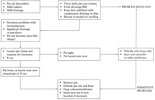 |
|
Table 11.3. Management of External Fixator Pin Site Problems
|
play in managing pin-site irritation. The typical situation in which a
patient requires oral antibiotics occurs when the pins pass through a
thick soft-tissue envelope, which, because of the patient’s activities
and rehabilitation, are moving on the pin, resulting in contamination
and a low-grade cellulitis in the absence of any evidence of pin
loosening or infection. This is most common in limb-lengthening and
deformity-correction procedures where tensioned wire ring fixators or
hybrid frames are being utilized. In these cases, I have found that a
few patients do well on oral cephalosporins for 10 days or more if
episodes of cellulitis occur. Always be alert for pin loosening and
evidence of deeper infection.
clinical appearance, have no place in the management of pin-site
complications. These cultures are nearly always positive, usually
represent normal skin flora, and are of no help in prescribing
appropriate treatment. I take cultures only when formal deep
debridement of a infected or potentially infected pin site is carried
out. These cultures are taken at the level of bone, preferably from a
curetting of the pin tract.
by either pin loosening, loosening of components on the frame, or both.
If deformity is noticed prior to consolidation of the fracture, then
usually it is correctable by addressing pin or frame problems. Because
of the nature of the fractures treated with external fixators, delayed
union
and
nonunion are common and are best approached by manipulation of the
frame or by bone grafting, as described previously. Conversion to some
type of internal fixation is much less common unless done very early,
as has been discussed. These issues are addressed in much more detail
in chapters on each specific bone and on nonunions in this section of
the book.
prosthetic devices to bone, to fix bone to bone, and to fix soft
tissues such as ligaments and tendons to bone. Perhaps the most
important use of screw fixation is interfragmentary compression, which
improves the mechanical stability of internal fixation by increasing
the friction between bone fragments. This minimizes micromotion between
the fragments by minimizing the effects of torsion, shear, and bending
forces.
Interfragmentary compression with a lag screw is the best example of
static compression. A screw functions as a lag screw when the threads
obtain purchase only in the far cortex, and the thread of the screw or
a nonthreaded portion of the screw passes freely through the cortex
immediately beneath the screw head. Screws can be made to function as
lag screws either by overdrilling the near cortex to prevent the
threads from gripping, or by having smooth shanks
in
the portion adjacent to the screw head. Clearly, interfragmentary
compression cannot occur if the screw threads cross the fracture site,
unless compression is achieved by a bone-holding forceps at the time
the screw threads cross the fracture. The screw then maintains, but
does not itself exert, compression.
on the density and quality of the bone. Other factors related to the
strength of screw fixation are the overall surface area of thread in
contact with the bone and the configuration of the thread relative to
the structure of the bone. Whether the hole is tapped or untapped
influences the frictional force developed between the screw and the
bone, and thus the tendency of the screw to back out. Because bone is
either cortical or cancellous, and each type has very different
structural characteristics, two types of specialized screws have been
developed—cortical and cancellous (Fig. 11.27 and Fig. 11.28).
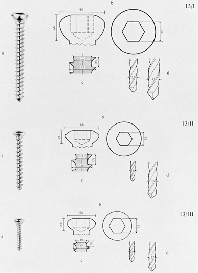 |
|
Figure 11.27. Cortical screws. Top:
A 4.5 mm cortical screw with a core diameter of 3 mm, outside thread diameter of 4.5 mm, and thread pitch of 1.75 mm. Notice that the underside of the screw head is hemispherical in cross section. A 3.2 mm drill bit is used for the threaded hole and a 4.5 mm drill bit for the gliding hole. Center: A 3.5 mm cortical screw. In the AO system, two varieties of this screw are now available—one with threads like those on a machine screw, known as the 3.5 mm cortical screw, and the one here, the 3.5 mm cancellous screw. The screw illustrated has a core diameter of 1.9 mm, an outside diameter of 3.5 mm, and a thread pitch of 1.75 mm. A 2 mm drill bit is used for the threaded hole, and a 3.5 mm drill bit for the gliding hole. Bottom: The 2.7 mm cortical screw is used for fixation of small fragments, as in the hand and foot. The thread has a core diameter of 1.9 mm and an outside diameter of 2.7 mm. The threads have a 1 mm pitch. A 2 mm drill bit is used for the threaded hole and a 2.7 mm bit for the gliding hole. (From Müller ME, Allgöwer M, Schneider R, Willenegger H. Manual of Internal Fixation. New York: Springer-Verlag, 1979:33, with permission.) |
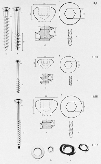 |
|
Figure 11.28. Cancellous bone screws. Top:
The two upper screws are standard AO 6.5 mm cancellous screws with spherical heads. The shafts are 4.5 mm in diameter, with 16 mm and 32 mm thread lengths. The screw threads have a core diameter of 3 mm, an outside diameter of 6.5 mm, and a thread pitch of 2.75 mm. For most applications, a 3.2 mm drill tip is used. If the shaft must pass through thick cortical bone, drill the cortex with a 4.5 mm drill. Center: A 4 mm cancellous screw with a core diameter of 1.9 mm, an outside diameter of 4 mm, and a thread pitch of 1.75 mm. A 2 mm drill bit is used. Bottom: Malleolar screw. The screw thread has the same profile as the 4.5 mm cortical screw, but a portion of the shank is unthreaded. The drill bit is 3.2 mm. Note the cutting tip, which allows the screw to be self-tapping in cancellous bone. In the ankle, this screw is used less often than the 4 mm cancellous screw. Various washers are available for both the 6.5 mm and the 4 mm screws. (From Müller ME, Allgöwer M, Schneider R, Willenegger H. Manual of Internal Fixation. New York: Springer-Verlag, 1979:28, with permission.) |
These screws have spherical heads and are threaded for the full length
of the shafts. A hexagonal screwdriver is used. Because there are no
flutes on the tips of these screws, the bone must first be tapped to
create threads for the screw. The advantage of tapping is that more
engagement of the screw threads into bone is possible (Fig. 11.29).
Because taps provide four cutting flutes, microfracture of the bone is
less likely to occur. Theoretically, this produces better hold of the
screw in bone. Disadvantages of tapping are that it requires an extra
step in the operative procedure and, because a rather smooth track is
established, the screw is more likely to loosen by backing out when it
is subjected to cyclical stress.
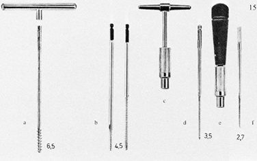 |
|
Figure 11.29. Tap for the 6.5 mm cancellous screw (a); short- and long-threaded taps for the 4.5 mm cortical screw (b); key handle for the 4.5 mm and 3.5 mm taps (c); 3.5 mm tap (d); handle for the 3.5 mm and 2.7 mm taps (e); and 2.7 mm tap (f). (From Müller ME, Allgöwer M, Schneider R, Willenegger H. Manual of Internal Fixation. New York: Springer-Verlag, 1979:35, with permission.)
|
tip are also used. They are manufactured from a titanium alloy, and
variations are available from several manufacturers (Fig. 11.30).
These new screw designs surpass the holding power of non-self-tapping
screws and are stronger due to their larger diameter and the use of
titanium alloy. The major advantages are that the extra step of tapping
is eliminated, and the screw is less likely to back out because of
better frictional hold between the screw threads and bone. The only
disadvantage is that 3–5 mm of screw tip must protrude from the bone to
achieve maximum thread surface in contact with bone in the opposite
cortex.
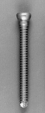 |
|
Figure 11.30. Self-tapping titanium alloy cortical screw.
|
have larger threads with a higher pitch and usually a smaller core
diameter, providing more surface area for purchase on bone. Because
cancellous bone is fairly soft and easily deformed, tapping usually is
not required. If the screw is inserted through cortical bone first,
however, it is usually necessary to tap the cortex; for this reason,
taps are provided for cancellous screws.
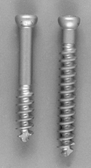 |
|
Figure 11.31. Self-tapping titanium alloy cancellous screws.
|
cancellous bone, do not tap. As the screw penetrates, it compresses the
bone to either side, thereby increasing the bone density in the
immediate vicinity of the screw thread; this improves the holding
power. Typically, cancellous screws have smooth shanks in the portion
immediately adjacent to the screw head so that an automatic lag effect
occurs without having to overdrill the near cortex. This is significant
in the larger 6.5 mm screws, where a very large hole would need to be
drilled in the near cortex to produce a lag effect. Varying thread
lengths are available (16 and
32 mm). Fully threaded cancellous screws are available as well.
fixation of the pelvis and fixation in the cancellous bone of
juxtaarticular fractures such as those of the tibial plateau. These
screws are inserted without tapping and take advantage of the
compressive effect of the bone around the screw, as described above.
Sometimes, a tap must be used to initiate penetration of the screw
through the thin cortical cortex. If the opposite cortex is to be
penetrated and it is more than one or two thread widths in diameter,
pressure must be maintained against the screw to penetrate the cortex
and to prevent stripping of the screw. This is the major disadvantage
of this technique. The major advantage is that taps and the aggressive
threads of cancellous screws do not need to be used in areas where
excessive penetration of these sharp cutting surfaces may threaten
neurovascular structures, and, in addition, a larger surface area of
purchase of the screw threads on bone results in more holding power.
This is a particularly good technique with self-tapping screws.
screw to be angulated in all directions within a washer or plate while
maintaining concentric contact between the screw and the side of the
plate. The only disadvantage of the spherical head is that it is more
prominent when used without a plate. This necessitates countersinking
to avoid prominence of the head and to avoid the stress created by
asymmetric contact of the underside of the head with the edge of the
predrilled screw hole. Washers (Fig. 11.28) often must be used with cancellous screws because the screw head tends to bury into the thin cortex overlying cancellous bone.
is in achieving interfragmentary compression. The screw head is driven
asymmetrically in the specially designed screw hole of the dynamic
compression plate, which was pioneered by the AO Group (71).
This design eliminates the need for an external compression device but
has the disadvantage of limiting the angulation with which the screw
can be driven. Extreme angulation of the screws may reverse the
compression force to some extent. The amount of compression achievable
is less than that possible with an outboard compression device,
described below in the General Principles of Plate Fixation section.
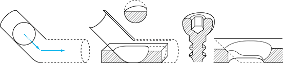 |
|
Figure 11.32.
Gliding-hole principle of the dynamic compression plate, in which the spherical underside of the screw glides down the incline plane of the screw hole in the plate. Interfragmental compression is achieved using a plate, without an external compression device. (From Müller ME, Allgöwer M, Schneider R, Willenegger H. Manual of Internal Fixation. New York: Springer-Verlag, 1979:71, with permission.) |
bone have spiked undersurfaces. Also available are nuts with attached
washers and screws. These improve fixation when the screw threads fail
to gain purchase because of poor bone quality or technical error. A
unique asymmetric nut is available in the Alta system (Fig. 11.33).
 |
|
Figure 11.33.
This Alta nut is usually used to lock two plates together in the system, but it can be used free as a washer-nut on the opposite cortex to enhance fixation in soft bone. The rectangular shape enhances delivery to the tip of the screw and increases the binding to the opposite surface (magnified). |
must be sharp and straight. Dull drill points will overheat and “kill”
bone. This can lead to premature mechanical failure of fixation and
also predisposes to infection. Bent drill tips wobble, producing a hole
larger than that required for the screw and thereby compromising
fixation. When a dozen or more drill holes are made during a fixation
procedure, drill points become dull and usually need to be replaced for
the next procedure. If a drill point is inadvertently run against a
metal surface such as a retractor, replace it, as dulling of the tip
compromises its cutting power and can overheat bone. Use the
proper-diameter drill point for each size of screw used. For cortical
screws, use a drill point equal to or slightly larger than the core
diameter of the screw. To produce a lag effect with cortical screws,
use a drill point equal to or slightly larger than the outside diameter
of the threads in the near cortex. For the screws used in the AO
systems, the appropriate sizes of drill points are shown in Fig. 11.27 and Fig. 11.28.
power drills, primarily because the wobble introduced by hand drilling
produces a slightly larger hole than desired. Power drills offer more
precision and are preferred. The major danger with both hand and power
drills is overheating due to excessive drilling speeds, particularly if
drill points are dull. High-speed drills designed for inserting wires
or for use with high-speed burrs are not suitable for inserting screws.
The usual drilling speed for drill points is 600 to 700 rpm. To avoid
bone necrosis, continually cool the drill point during drilling by
irrigation with sterile saline. If drilling is prolonged, withdraw the
drill point and frequently clean its flutes of bone.
structures, must be protected during drilling. In addition, avoid
scratching fixation devices such as plates. To protect soft tissues and
plates, use drill sleeves over the drill point. Drill sleeves also give
better purchase on bone and increase the accuracy of drilling.
As a drill point begins to exit a cortical bone surface, it slows
slightly and the pitch of the drilling sound changes. Use this as a
signal to ease pressure on the drill, and prepare to arrest the forward
motion of the drill to avoid overpenetration.
shaft to determine screw length, but for the most part separate depth
gauges are used (Fig. 11.34). Incorrect
measuring can occur if you accidentally hook only the near cortex, or
hook soft tissues or a bone surface other than the one desired, on the
far side. In addition, improper mounting of the measuring tine in the
depth gauge can produce erroneous measurements. After insertion of
screws, always verify appropriate screw lengths either by palpation or
by intraoperative radiographs, and check the depth gauge if lengths are
inappropriate. In most situations, the appropriate screw length is such
that one full thread exits the far cortex. This is unnecessary with
cancellous screws in most applications and in fact may be inadvisable
where the sharp tip of the screw threatens soft tissues on the opposite
side of the bone.
 |
|
Figure 11.34.
Alta depth gauge. Insert the hook into the screw hole, hook the far cortex and read the screw length off the shank. This gauge automatically adds 3 mm to compensate for the self-tapping tip of the screw. |
aware of. In the AO and similar systems, cortical screws are generally
available in 2 mm increments. The depth gauge measurement is designed
to place just one thread of the tip of the screw through the opposite
cortex when the screw head is fully seated. If measurement indicates an
odd number, such as 21 mm, then the next larger screw is used, in this
case 22 mm. This ensures that the maximum number of threads is always
engaging the far cortex.
3 mm or so of the tip of the screw is made up of the flutes, which are
a part of the self-tapping feature. To be certain that a maximum number
of screw threads engage the far cortex, depth gauges in these systems
usually compensate for this and provide a measurement that allows
approximately 3 mm of the screw tip to protrude beyond the far cortex.
In addition, self-tapping screws are more frequently available in
titanium systems where the plates being used are quite flexible and
conform much more closely to the bone than steel. This may result in
the screw tip protruding through the opposite cortex 5 mm or more,
particularly in the first several screws used to fix the plate
to
the bone. Therefore, it is important to check the screw lengths by
either palpation or radiographic visualization after completion of
insertion of all screws in the plate, as it may be necessary to replace
them if excessive length of the tip beyond the opposite cortex poses a
problem. Penetration of 5 mm or so in many locations where the screw
tip is well buried and not in the vicinity of neurovascular structures
presents no problem; if the screw tips are on a subcutaneous border
beneath skin, however, they can be quite bothersome to the patient and
must be adjusted. If an in-between-size screw is needed in these
systems, choose the next smaller screw, rather than the next longer
screw as in AO system.
required to insert it, back it out, clean the flutes, and readvance the
screw. This avoids microfractures of the bone. Very dense cortical bone
may require tapping of the near cortex. The screws most commonly used
require tapping (Fig. 11.29). The correct tap
for a given screw diameter must be used. In the AO system, a short tap
is provided where lag screw fixation with cortical screws makes tapping
of the near drill hole undesirable. Tapping can be done by hand or with
power. To avoid microfracture of the bone and breakage of the tap,
reverse the tap for a half turn every several terms to clear bone
chips. Use low rpm settings and frequent reversals if tapping with
power.
but the most commonly used are hex-socket-type heads and modified
cruciate heads, in which the tines are rounded at the corners. Many
names are applied to the latter tips, but they are most often referred
to as Woodruff tips. A standard industrial screwdriver tip recently
introduced is the Torx used in the Alta system. It provides superior
driving torque, particularly in titanium alloy screws. It fits snugly
into the screw, providing a self-retaining feature that is helpful in
screw placement.
hole drilled. Once the medullary canal is entered, it is possible to
miss the opposite drill hole. Inexperienced surgeons should always
drive screws by hand; hand-driving is also necessary when the bone
quality is poor. A power driver with a screwdriver tip is useful when
multiple screws are being inserted into cortical bone, but this
technique requires experience.
result in fracture of the bone or failure of the screws. Overtightening
also predisposes the screw to premature failure. In healthy young
cortical bone, it is generally recommended that about 25 inch-pounds be
applied to the screw. This can be learned by using a torque
screwdriver; experienced surgeons can sense the appropriate tightening
of a screw.
 |
|
Figure 11.35.
Lag screw fixation. A: Overdrilling the near cortex produces a “lag” effect and interfragmentary compression. B: Threading both cortices leaves a gap between the two bone fragments. (From Müller ME, Allgöwer M, Schneider R, Willenegger H. Manual of Internal Fixation. New York: Springer-Verlag, 1979:37, with permission.) |
-
For effective interfragmentary
compression, overdrill the cortex adjacent to the screw head, so thread
purchase is achieved only in the opposite fragment. -
Notice that threading both fragments produces persistent distraction between the fragments.
cross a fracture or osteotomy interface, better purchase is obtained by
bicortical fixation. In rare circumstances, it is undesirable to reduce
the distance between two bone surfaces; the classic example is in
fixation of the distal tibiofibular syndesmosis. In this situation, it
is undesirable to overcompress the joint between the tibia and the
fibula after reduction has been achieved. Instead, use a fully threaded
cortical screw in each of the four cortices of the tibia and fibula,
engaging all cortices with threads. To achieve lag screw fixation with
cortical screws, two techniques
are available, depending on which screw hole is drilled first: the gliding hole or the threaded hole.
-
In simple fractures where most of the
fracture line is visible, reduce the fracture anatomically and hold it
with bone-holding forceps. -
To provide optimal alignment between the
screw holes and to prevent displacement of the fracture as the screw is
tightened, insert one or more interfragmentary lag screws, drilling the
gliding hole first, then placing a drill sleeve and drilling the
threaded hole (Fig. 11.36).![]() Figure 11.36.
Figure 11.36.
Fixation with a lag screw after reduction of the fracture using the
gliding-hole-first technique. (From Müller ME, Allgöwer M, Schneider R,
Willenegger H. Manual of Internal Fixation. New York: Springer-Verlag, 1979:37, with permission.) -
Protect the soft tissues by using a 4.5
mm tap sleeve as a drill guide. Drill the gliding hole in the near
cortex with a 4.5 mm drill bit (Fig. 11.36A). -
Insert a drill sleeve into the hole until
it makes contact with the opposite cortex. This sleeve has an outer
diameter of 4.5 mm and an inner diameter of 3.2 mm (Fig. 11.36B). -
Drill the opposite cortex with a 3.2 mm drill bit (Fig. 11.36C).
-
Use a countersink to create a recess for the screw head in the near cortex (Fig. 11.36D).
-
Use the large depth gauge to measure screw length (Fig. 11.36E).
-
Tap the drill hole in the opposite cortex with the short 4.5 mm tap (Fig. 11.36F).
-
Insert the correct-length 4.5 mm cortical
screw until the fracture site is snugly approximated. If more than one
screw is to be placed across a fracture, do not completely tighten the
screws until they are all in place (Fig. 11.36G).
the configuration of the fracture or osteotomy will make accurate screw
placement difficult, drill the gliding hole first either from the
outside or inside in the near bone fragment before reducing the
fracture. This permits precise placement of the drill hole, which
ensures that the screw does not enter the fracture line and that
adequate bone stock is available for purchase (Fig. 11.37).
 |
|
Figure 11.37.
Screw fixation prior to reduction of the fracture, using the gliding-hole-first technique. (From Müller ME, Allgöwer M, Schneider R, Willenegger H. Manual of Internal Fixation. New York: Springer-Verlag, 1979:39, with permission.) |
-
Locate the appropriate site in one bone
fragment for the gliding hole. Drill the hole using the 4.5 mm drill
through a tap sleeve (Fig. 11.37A, Fig. 11.37B). -
More accuracy can sometimes be obtained by drilling from inside to outside (Fig. 11.37B).
-
Reduce the fracture, insert the drill sleeve, drill the threaded hole, and complete the screw fixation (Fig. 11.37C).
-
Where it is not convenient to make the
gliding hole first, drill the threaded hole with the 3.2 mm drill bit
inside to outside first (Fig. 11.37D). -
Insert the pointed drill guide into this hole (Fig. 11.37E).
-
Reduce the fracture, place a 4.5 mm tap
sleeve through the sleeve of the pointed drill guide, and drill the
gliding hole with a 4.5 mm drill, taking care to maintain appropriate
alignment. While maintaining reduction, insert a screw and complete the
fixation (Fig. 11.37C, Fig. 11.37D and Fig. 11.37E).
principles applied to the fixation of a long, spiral fracture. In
general, lag screw fixation of an oblique or spiral fracture requires
neutralization by a plate if sufficient stability is to be achieved to
allow immediate rehabilitation without external protection. In very
long or oblique diaphyseal fractures, and in some similar fracture
configurations in the epiphysis and metaphysis, it may be possible to
achieve good fixation with lag screws alone. When only lag screws are
used, however, external protection with a functional brace and delayed
weight bearing are advised. For fixation of a noncomminuted diaphyseal
fracture with lag screws alone, the fracture length must be at least
three times the diameter of the shaft at the site of the fracture.
 |
|
Figure 11.38.
Interfragmentary screw fixation of a long spiral fracture, showing the appropriate orientation of the screws along the fracture. Note that they are approximately at right angles to the long axis of the bone, yet spiral about the bone to maintain optimal alignment to the plane of the fracture lines. (From Müller ME, Allgöwer M, Schneider R, Willenegger H. Manual of Internal Fixation. New York: Springer-Verlag, 1979:41, with permission.) |
each section of the fracture to obtain maximum interfragmentary
compression. Proper placement avoids shear stresses that will cause the
fracture to slide on itself. In spiral fractures, this requires the
screws to spiral down the fracture site. In addition, in most fracture
configurations, the screws are best placed at right angles to the long
axis of the shaft of the bone, because longitudinal compressive forces
will cause the screws to tighten rather than loosen.
metaphyseal regions with cancellous screws and washers, using lag screw
fixation. At least two (often three) screws are required to prevent the
fragments from rotating. Unless the bone is osteoporotic, cancellous
screws need not exit the opposite cortex. In fact, in articular
locations this is usually inadvisable because the sharp tip of the
screw may impinge on neurovascular structures or present an
uncomfortable prominence under the thin skin over joints. A typical
configuration is shown in Fig. 11.39.
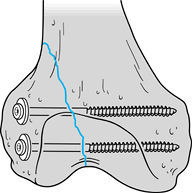 |
|
Figure 11.39.
Lag screw fixation of an intraarticular fracture of the femoral condyles using two 6.5 mm cancellous screws with washers. (From Müller ME, Allgöwer M, Schneider R, Willenegger H. Manual of Internal Fixation. New York: Springer-Verlag, 1979:31, with permission.) |
application of 4 mm cancellous screws to internally fix an
intraarticular fracture of the talus in an immature limb. Note that the
two screws are perfectly parallel because the drill holes were placed
with the pointed drill guide, which guarantees parallel drill holes.
This is important for optimal lag effect. Figure 11.41
shows similar screws used in a more common application, a displaced
fracture of the medial malleolus. Again, the pointed drill guide is
used to ensure that the screws are parallel. The versatility of
interfragmentary cancellous screw fixation is shown in Fig. 11.42,
in which a displaced acetabular fracture is fixed with three screws
because it was inconvenient to place a plate. As described, nontapped
cortical screws also work very well in the pelvis if the fracture
surfaces are well compressed by bone-holding forceps.
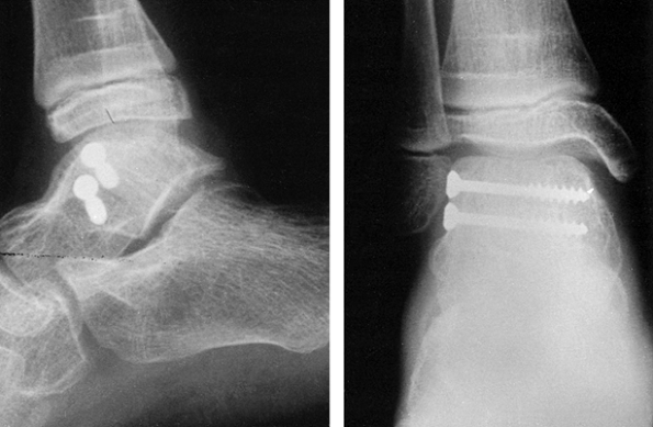 |
|
Figure 11.40. Displaced fracture of the body of the talus in an immature ankle has been internally fixed with two 4.5 mm cancellous screws.
|
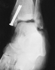 |
|
Figure 11.41. Fixation of a displaced fracture of the malleolus with two 4 mm cancellous screws.
|
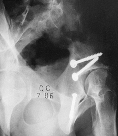 |
|
Figure 11.42.
Internal fixation of a complex fracture of the acetabulum using only cancellous lag screws. Although these were sufficient in this patient, in some fractures plate fixation would be required as well. |
as a vertical spilt fracture of a lateral tibial plateau, are fixed
with interfragmentary screws alone, vertical shear forces tend to
displace the condyle inferiorly. This can be neutralized by placing a
buttress screw to support the fragment. Either a cancellous or a
cortical screw can be used, depending on the location of the fracture
and the quality of the bone.
-
Place a drill hole immediately adjacent
to the inferior tip of the proximal fragment, and drill in a bicortical
fashion at right angles to the longitudinal axis of the tibia. -
Then place a screw with a washer. Be
certain that the screw shaft contacts the tip of the fragment and the
washer is brought snugly against the inferior spike of bone. This will
prevent inferior shift of the fragment (Fig. 11.43).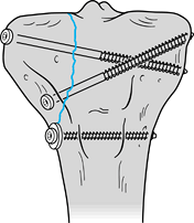 Figure 11.43.
Buttress screw (antiglide screw). Insert at the tip of the condylar
fragment with the washer overlapping the proximal fragment, to prevent
inferior subsidence of the condyle.
interfragmentary compression. Threads are present at both ends of the
screw, with a pitch differential between the leading and trailing
threads. Interfragmentary compression is achieved by the difference in
thread pitch, so a screw head is not required. The absence of a screw
head makes it possible to insert Herbert screws through articular
surfaces without the head being prominent. Originally designed for
scaphoid fractures, current indications include osteochondral
fractures, osteochondritis dissecans, capitellar fractures, radial head
fractures, and small joint arthrodesis. A disadvantage is that the
Herbert screw can be difficult to remove. The Herbert screw used in an
illustrative case is shown in Fig. 11.44.
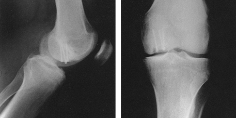 |
|
Figure 11.44.
Internal fixation of osteochondritis dissecans by Herbert screws. The trailing thread is countersunk beneath the articular surface of the medial femoral condyle. |
intramedullary nails. Most systems use a smooth-shanked screw with
special features to ease removal (Fig. 11.45).
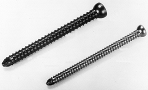 |
|
Figure 11.45. Crosslocking screw. Note the thick shank and low profile thread to enhance strength.
|
Potential benefits of this system are less soft-tissue dissection and
the presence of a guide wire for provisional fixation and for accurate
screw placement (Fig. 11.47). These screws are
most often used for percutaneous fixation or femoral neck fractures,
where fluoroscopic imaging of guide-wire placement helps to ensure
appropriate screw length and screw position. Placement requires initial
placement of a guide wire. A hollow drill is used over the guide wire
and a cannulated tap is used if required. Cannulated screws are best
inserted under fluoroscopic control. A depth gauge or measurement from
a calibrated drill bit determines the length of screw to be used.
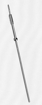 |
|
Figure 11.46. A cannulated screw can be inserted over a previously placed guide wire.
|
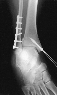 |
|
Figure 11.47.
Intraoperative radiograph of internal fixation of medial malleolus fragments using cannulated screws. The guide wires are helpful in achieving and maintaining the reduction of the fracture until screw insertion is completed. |
noncannulated screws, particularly in the small fragment size, and they
break more easily when removal is attempted (Fig. 11.48).
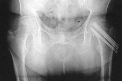 |
|
Figure 11.48. Percutaneous internal fixation of a femoral neck fracture with multiple cannulated screws.
|
manufacture absorbable screws. Indications include children when
hardware removal can be avoided, and in the internal fixation of
juxtaarticular fractures such as those of the medial malleolus, where
high strength is not required and removal of hardware is often required
because of the subcutaneous location of the screw. Bucholz et al. (23) have described good success with absorbable screws.
bone for repair or reconstruction using a cancellous bone screw driven
through the soft-tissue structure, with a spiked washer to obtain
purchase on the ligament or tendon. Although this works well, one
disadvantage is that the area of soft tissue fixed with the screw and
washer becomes avascular due to the pressure. Sometimes this
avascularity will lead to failure of fixation before adequate
soft-tissue healing.
ligaments and tendons to bone, either by bone blocks or by indirect
fixation. Daniel et al. described a step-cut tibial channel to capture
the tendon preparation (35). Sutures are passed
through the tendon preparation using a double-loop technique and are
then tied to the head of a cancellous screw (Fig. 11.49). The interference screw technique (Fig. 11.50)
described by Lambert is easier to perform and in my opinion provides better fixation (65).
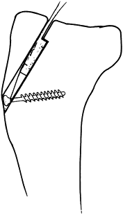 |
|
Figure 11.49.
Step-cut tibial channel for fixation of a bone ligament preparation for reconstruction of the anterior cruciate ligament. Sutures placed through the bone–tendon preparation by double-loop technique are tied to the head of a cancellous screw. (From Daniel DM, Robertson DB, Flood DL, Biden EN. Fixation of Soft Tissue. In: Jackson DW, Drez D Jr, eds. The Anterior Cruciate Deficient Knee. St. Louis: CV Mosby, 1987, with permission.) |
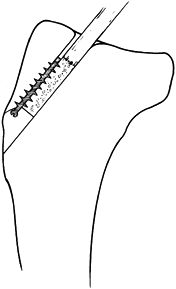 |
|
Figure 11.50.
Interference-fit fixation of the bone plug on a bone–tendon preparation for reconstruction of the anterior cruciate ligament using a 30-mm-long, 6.5-mm-wide cancellous screw. Fixation depends on a snug fit of the bone plug in the drill hole. (From Lambert KL. Vascularized Patellar Tendon Graft with Rigid Internal Fixation for Anterior Cruciate Ligament Insufficiency. Clin Orthop 1983;172:885, with permission.) |
of suture anchors have become available that are based on the molly
bolt principle or that are screws. Sutures of various sizes and
materials are attached to these devices. When needing to attach
ligament, tendon, or capsule to bone, these devices are inserted into
the cancellous bone at the attachment site, securing the suture to the
bone, which is then used to attach the soft tissue (Fig. 11.51). These have offered significant improvements, particularly where arthroscopic repairs are performed.
 |
|
Figure 11.51. Mitek suture anchor (magnified).
|
probably the oldest means of fracture stabilization. Many types of
plates have been applied to bone, some by screws, others with the help
of wire loops. However, not until Danis in 1949 were plates applied
with axial loading (compression) of the bone and fracture underneath (36). It was observed that this type of compression fixation leads to fracture healing without visible external callus (soudure autogène,
or direct bone healing). From this observation, in the late 1950s,
Müller developed the original AO round-hole compression plate with the
removable compression device. Bagby and Janes developed a similar plate
(7,8). Since that time,
plating has become a well-established means for fixation of a large
variety of fractures and nonunions, and many different plate designs,
forms of application, and plate functions have been described. For a
review of the literature, see The Dynamic Compression Plate by Allgöwer et al. (2).
in principle be fixed with a plate, other devices for fracture
fixation, such as the interlocking nail and the external fixator, have
advantages over plates in certain situations, especially in diaphyseal
fractures of the femur and tibia.
and size) or function. Both type and function often correspond to a
specific application (for example, the L-shaped buttress plate for
fractures of the tibial plateau). On the other hand, a given plate may
have different functions, depending on (a) the mechanical configuration
of the bone–plate conjunction, resulting in static compression, dynamic
compression (tension band), neutralization, and buttressing; (b) which
part of the bone is stabilized (metaphysis or diaphysis); and (c) the
specific fracture configuration.
to provide static compression of a diaphyseal fracture, thereby leading
to rapid bony union, as was shown experimentally in sheep (82).
After fracture reduction, compression or axial loading was applied with
the help of the removable compression device. Today, it is known that
in most cases the originally instituted compression force of up to
80–90 kilopascals (kp) was lost after the remaining screws were
introduced into the round holes of the plate. The reason for the
success of the so-called compression plate, therefore, was most
probably not compression in the first place, but rather the better
method of fracture fixation with newly designed implants that were also
applied differently (e.g., by power drilling, pretapping). In
hypertrophic nonunions, the primary achievement of the compression
plate was better approximation of the nonunited fragments and optimal
stabilization, allowing calcification of the interposed tissues. If
properly placed on the tension side (convexity) of the nonunion, the
compression plate acts as a tension band, which actually provides
dynamic rather than static compression.
fracture healing, it became evident that to stimulate bone remodeling
by creeping substitution, a signal was needed. The best way to transmit
or generate this signal appeared to be physiologic loading of bone by
controlled weight-bearing.
For
this purpose, the original AO/ASIF (Association for the Study of
Internal Fixation) round-hole plates were probably somewhat less
forgiving when not ideally applied. Too much axial loading could lead
to fatigue failure of the plate or loosening of the screws rather than
to bony union.
introduced. The self-compressing effect by eccentric screw placement,
combined with the possibility of a gliding or sliding effect (Fig. 11.52)
between the screw head and the plate hole, allowed a more physiologic
force transmission within bone during weight bearing. Furthermore,
thanks to the spherical configuration of both screw head and plate
holes, the compression instituted initially was maintained throughout
the procedure, even if the screws were not placed at a right angle to
the plate.
 |
|
Figure 11.52. A: Dynamic compression plates of different dimensions. From top to bottom: broad, 4.5 mm; narrow, 4.5, 3.5, 2.7 mm. B:
Schematic representation of the spherical gliding principle of the DCP. (From Müller ME, Allgöwer M, Schneider R, Willenegger H. Manual of Internal Fixation. New York: Springer-Verlag, 1979:235, with permission.) |
Tensile pre-stressing of a straight plate produces axial compression in
the fracture. The area underneath the plate is compressed, while the
opposite cortex shows a gap. To increase the amount of bone surface
being compressed (including the opposite
cortex),
it is advisable to contour the plate to approximate the cortex opposite
the plate. Another possibility to prevent a slight gapping of the
osteotomy or fracture line in the far cortex is to place a lag screw
across the fracture or osteotomy plane (Fig. 11.54).
 |
|
Figure 11.53.
Static compression in a transverse fracture (humerus) fixed with a slightly overcontoured plate. Axial compression is obtained via the removable tension device. A: Plate application with the tension device. B: Equal distribution of compressive forces. (From Müller ME, Allgöwer M, Schneider R, Willenegger H. Manual of Internal Fixation. New York: Springer-Verlag, 1979:223, with permission.) |
 |
|
Figure 11.54. Fracture fixation is improved by placing an interfragmentary lag screw through the plate. A: Placement of interfragmentary lag screw across a 3.5 plate; drilling of a gliding hole with a 3.5 mm drill bit. B: Drilling of a threaded hole with a 2.5 mm drill bit and corresponding drill guide. C:
Interfragmentary compression across plate and fracture is achieved by tightening the lag screw. (From Müller ME, Allgöwer M, Schneider R, Willenegger H. Manual of Internal Fixation. New York: Springer-Verlag, 1979, with permission.) |
a medullary nail. The indications for a static compression plate,
therefore, are less common; these include transverse fractures of the
humerus and forearm bones.
principle of tension band fixation and demonstrated its application in
operative fracture treatment (79). Every
eccentrically loaded bone is subjected to bending stresses and deforms
in a typical manner, with a gap on the convex or tension side and
compression on the concave side of the bone (Fig. 11.55A).
To restore the load-bearing capacity of an eccentrically loaded bone,
the tensile forces on the convex side must be absorbed by a tension
band (wire or plate) (Fig. 11.55B). The bone
itself—especially the cortex opposite the tension band—must be able to
withstand axial compression; this requires a medial buttress, usually
supplied by the intact cortex. Thus, the implant
absorbs
the tension forces, and the underlying bone the forces resulting from
compression. Loading (e.g., by partial weight-bearing) results in a
dynamic increase of the axial interfragmental compression. In the
absence of a medial buttress, which absorbs the compression forces, the
plate is subjected to repeated bending stresses, which inevitably lead
to fatigue failure and implant breakage (Fig. 11.55C).
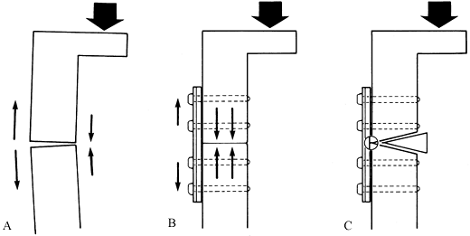 |
|
Figure 11.55. Tension band plate in femur. A: Eccentric loading of the femur results in tensile forces on the lateral side and compression on the medial aspect of the bone. B:
In the presence of a good bony buttress, the lateral plate acts as a tension band. The plate is therefore stressed only in tension, the bone in compression. C: In the absence of a bony buttress—due to a cortical defect—the plate undergoes cyclic bending, leading rapidly to fatigue breakage. |
difficult to identify the tension or compression side of a fresh
fracture, but in a malunion the aspect (lateral, medial, or posterior)
on which the tensile forces are most active is usually clearly visible (Fig. 11.56).
The best indications for a tension band plate, therefore, are fractures
in the subtrochanteric area of the femur (requiring a 95° blade plate
or broad DCP), certain olecranon fractures (one-third tubular or 3.5 mm
plate), and nonunions.
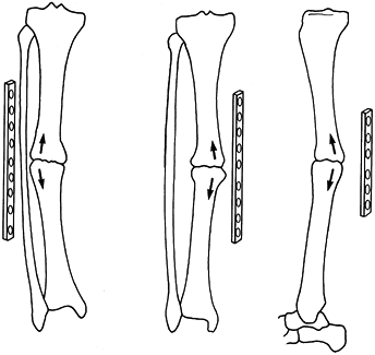 |
|
Figure 11.56.
Tension band plate in nonunions. To act as a tension band, the plate must always be placed on the tension or convex side of the bone. A: Lateral position. B: Medial position. C: Posterior position. (From Müller ME, Allgöwer M, Schneider R, Willenegger H. Manual of Internal Fixation. New York: Springer-Verlag, 1979:731, with permission.) |
but in many instances this fixation will not suffice for early active
movement or partial weight bearing. To protect the lag screw fixation
from bending, torsion, and shearing forces, a neutralization or
protection plate is added (Fig. 11.57C).
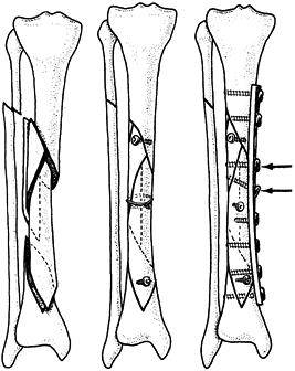 |
|
Figure 11.57. Neutralization plate in the tibia. A: Comminuted, multifragment fracture. B: After anatomic reduction and preliminary fixation with two lag screws and a cerclage wire. C:
A neutralization or protection plate has been added on the medial aspect of the tibia, with two additional lag screws through the plate (arrows). (From Müller ME, Allgöwer M, Schneider R, Willenegger H. Manual of Internal Fixation. New York: Springer-Verlag, 1979:33;581, with permission.) |
fix to the bone with all screws in a neutral position. Place a lag
screw across the fracture through the plate whenever possible, as this
greatly improves the neutralizing bone/plate system (Fig. 11.57C).
intraarticular fractures that are a combination of cleavage (T or Y),
with or without impaction of cartilage and subchondral cancellous bone.
After reconstruction of the articular surface and grafting of the bone
defect, one or two buttress plates will fix the articular fragments to
the shaft and support or buttress the metaphyseal area (Fig. 11.58).
Typical indications for buttress plating are fractures of the distal
humerus, the tibial plateau, and the tibial pylon, and compression
fractures of the distal radius. Accordingly, all T and L-shaped plates
are designed for buttress functions. If a DCP with gliding holes is
applied for buttressing, the
screws must be introduced at the end of the gliding slope to prevent further collapse.
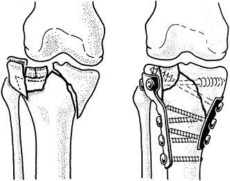 |
|
Figure 11.58. Buttress plates in tibial plateau fracture. A: Bicondylar plateau fracture with impaction of lateral articular surface. B:
Reduction and stable fixation with two buttress plates: L or T plate laterally, tubular plate medially. (From Müller ME, Allgöwer M, Schneider R, Willenegger H. Manual of Internal Fixation. New York: Springer-Verlag, 1979:33;573, with permission.) |
For this purpose Weber usually applies semi- or one-third-tubular
plates in such a way as to prevent the tip of an oblique fracture from
displacing due to muscle pull. For example, in a type B fracture of the
lateral malleolus (Fig. 11.59), the three-hole,
one-third-tubular plate is placed posteriorly and thereby locks the tip
of the distal fragment into an anatomically correct position.
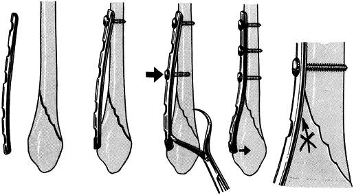 |
|
Figure 11.59.
Antiglide plate (Weber). A 3.5 dynamic compression plate or one-third tubular plate placed dorsally on the distal fibula prevents dislocation of distal fragment. (From Müller ME, Allgöwer M, Schneider R, Willenegger H. Manual of Internal Fixation. New York: Springer-Verlag, 1979:33;609, with permission.) |
the AO Group in the late 1950s, the major problems encountered in plate
fixation of fractures, other than the usual surgical complications,
were early plate failure, screw breakage, and screw pullout. Plates
were relatively weak, and the principles of obtaining a biomechanically
stable reconstruction through improvements in interfragmentary contact
were not yet well known. Screws were still based on designs from the
woodworking and metal industries, and their thread designs were not
ideal for fixation in bone. In addition, most screws were self-tapping;
this self-tapping feature was not well designed and led to microcracks,
which hindered the hold of the screw in bone.
obtainable with AO implants led to a new set of clinically significant
problems: bone loss under the plate, fracture at the ends of the
plates, or refracture through the fracture site or screw holes after
plate removal. Anderson et al. (5) and Hidaka and Gustilo (52)
had a 22% incidence of refracture after plate removal using the
standard, narrow 4.5 mm AO plate on fractures of the radius and ulna.
Chapman et al. (27) were able to eliminate refractures in
plate fixation of the radius and ulna by using the AO/ASIF 3.5 mm system.
possible causes: stress protection, and devascularization followed by
revascularization. Studies by Woo et al. (115), Coutts et al. (32), Uhthoff and Dubus (103),
and others demonstrate that stiff plates, when applied to healing
fractures, result in weaker fracture callus and, when left in place for
prolonged periods, weakening of the bone under the plate due to bone
resorption. These authors felt that this effect was due to “stress
shielding.” In accordance with Wolff’s law, introducing a rigid member
across a fracture site alters the signals influencing the homeostatic
mechanisms controlling bone apposition and resorption, so that the
fracture heals with weaker callus and bone resorption occurs under the
plate and in the surrounding cortex.
others have demonstrated devascularization of the cortex secondary to
soft-tissue stripping and disturbance of the intrinsic blood supply to
bone by the application of the plate and insertion of screws.
Revascularization of the bone results in bone resorption. The
hypervascularity associated with that is most evident under the plate.
designs have addressed both issues by producing more flexible plates
from materials with a lower modulus of elasticity, such as titanium,
titanium alloys, carbon fiber, or polymer, and by newer configurations.
Only titanium is currently in use clinically, however.
or other alloys. Titanium is more flexible than surgical steel, yet
stronger. Howmedica (Rutherford, NJ) produces a modular bone fixation
system from 6-4 titanium in an attempt to optimize the environment for
fracture healing. The modular system allows plates of different lengths
and types to be interconnected by dovetailing (Fig. 11.60).
This modular feature reduces the need for soft-tissue stripping to
place the plates. The use of larger oval holes in the plate, which will
accommodate two screws, permits fixation with shorter plates and
increases the range of angles through which screws can be placed; this
enhances fixation. The railed design of the plate limits plate contact
with the bone to potentially enhance revascularization. A new plate
from the AO Group known as the limited contact dynamic compression
plate (LCDCP), also of titanium, is an effort to achieve the same goals
(Fig. 11.61).
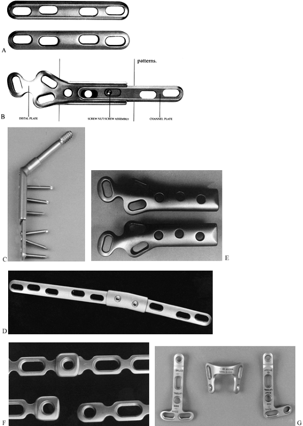 |
|
Figure 11.60. Alta modular titanium plating system. A:
The Alta channel plate (extension plate) features a railed undersurface, holes for single or double 5.0 mm screws, and a rounded configuration for insertion into a dovetail. B: The underside of an Alta distal femoral fracture plate, showing the dovetail connection between the two plates. If needed, they can be preassembled and fixed together with a screw and nut. C: Alta compression hip screw with the side plate dovetail holding a four-hole channel plate. Note the double screw hole configuration. The channel plate is available in three lengths. D: The channel plates can be connected with this double dovetail. This modularity drastically reduces the implant inventory and increases versatility. E: The distal femoral fracture plate seen from its top surface. The notch in the end of the plate permits insertion of two interfragmentary screws. The three double screw holes permit multiple screw fixation into the condyles. F: The dovetail is also featured in the Alta 3.7 mm small reconstruction plate, which has oval holes to accommodate two 3.7 mm screws or a 5.0 mm cortical screw (enlarged photograph). G: Specialized L, T, and U plates can be interlocked with the dovetail of the 3.7 mm plates. (Illustrations courtesy of Howmedica, Rutherford, NJ.) |
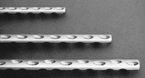 |
|
Figure 11.61.
The AO titanium low-contact dynamic compression plate. Its unique configuration offers fewer stress concentration points and less contact with bone to enhance preservation of the blood supply to bone. |
eliminated the need for tapping, removing one step from the fixation
process. The self-cutting threads and titanium
material
provide better frictional hold between the screw and bone, preventing
screw backout. The new four-fluted design of the Alta screw reduces the
heat of insertion and prevents microcracks of the cortex.
Their modulus of elasticity is even closer to that of bone, but they
cannot be molded during surgery and some tend to be quite brittle. Thus
far, they have not been found to be practical in clinical applications.
Other efforts to make plate and screw fixation more compatible with
normal bone physiology have been directed toward the development of
resorbable plates and screws, or placing resorbable surfaces on the
plate–bone or plate–screw interface. Resorption results in eventual
loosening of the construct, thereby allowing more physiologic
transmission of stresses. All of these are experimental at present and
have not entered clinical practice.
be used as tension bands if possible and therefore placed on the convex
surface of bones. This is particularly true for the radius, where
plates are usually placed on the dorsal lateral surface, and for the
femur, where they are placed anterolaterally. In the humerus, plate
location is dictated more by the anatomy of the surgical exposure, and
generally the plate is placed laterally or dorsally. The bending forces
about the tibia are less predictable, but generally plates are best
placed on the lateral surface because of the excellent soft-tissue
coverage provided. In general, try not to place plates in subcutaneous
locations, as skin slough or infection may result in plate exposure. In
addition, plates in subcutaneous locations are more likely to produce
symptoms. However, the practical aspects of fixation demand placement
of plates in subcutaneous locations in some circumstances, such as
plating of the olecranon and the lateral malleolus.
-
When exposing the fracture, limit
soft-tissue stripping to just the surface on which you expect to place
the plate. Avoid the use of retractors and bone-holding forceps, which
require circumferential stripping of bone. Fine-pointed tenaculum-type
bone-holding forceps are best. -
There seems to be no advantage to leaving
the periosteum intact beneath the plate. For most plates in common use
today, application of the plate on the periosteum results in complete
loss of blood supply to the periosteum. In addition, the fixation of
the plate to bone is less secure, due to the intervening soft tissue.
It is more difficult to obtain an anatomic reduction, particularly in
comminuted fractures. On the other hand, maintaining soft-tissue
attachments to bone is important. Newer “point contact” plates may
change this advice. -
If very small butterfly fragments are
involved, maintaining soft-tissue attachments to the butterfly may make
the fixation of the fracture exceedingly difficult and may result in
less-than-optimal reduction. In such cases, I do not hesitate to detach
small bone fragments from soft tissues to enhance the ability to obtain
fixation. These small fragments usually revascularize very quickly. -
To ensure that bone union occurs in the
presence of such comminution, however, apply a cancellous bone graft
across the comminuted zone. -
Accurate reduction and apposition of
butterfly fragments is particularly important when their absence would
leave a gap opposite the plate. This dramatically increases the bending
stresses on the plate and could lead to early fatigue failure of the
plate. -
After exposing the fracture site, clean
the fracture ends of all organized hematoma and soft tissue. Strip the
periosteum from the fracture ends 1–2 mm, just enough to delineate the
fracture surface.
reduced before plate application, and this simplifies fixation.
Unstable fractures pose a challenge, particularly if excessive
soft-tissue stripping is to be avoided. In simple oblique or spiral
fractures, or those with small butterfly fragments where there is good
cortical contact, often the fracture can be reduced with a small
tenaculum forceps and preliminary fixation obtained with an
interfragmentary lag screw. Application of the plate then is
simplified. In more unstable and comminuted patterns, a different
approach may be necessary. If a major butterfly is present, the best
approach may be to fix the butterfly to one fragment with an
interfragmentary lag screw, which then may produce a stable pattern
that can be reduced and easily plated. If this is impossible, I advise
using the plate to provide the mechanism for reduction of the fracture:
-
Precontour the plate, select the
approximate location for the plate, and choose the point for the first
screw hole on one side of the fracture. If necessary, lay the plate on
the surface of the bone on one side of the fracture and mark the site
for the screw with a methylene blue marking pen. -
Drill for the screw without the plate in place, and then secure the plate to one fragment with one screw.
-
Tighten the screw to achieve reasonable
stability, but do not overtighten it, as this may interfere with the
reduction. Then reduce the fracture and stabilize it using a tenaculum
or small plate-holding forceps on the side of the plate not attached to
bone.
reduction is immensely helpful. This avoids the common struggle in
which the fracture is reduced and held with multiple bone forceps, but
then the surgeon finds that the plate cannot be placed. Removing the
forceps to place the plate then results in loss of stability, and a
prolonged struggle ensues to hold the reduction while applying the
plate.
supracondylar region of the femur and in pylon fractures, use indirect
reduction techniques as popularized by Mast to avoid devascularization
of the many bone fragments (71). To achieve
length, apply a femoral distractor and then use it to pull the fracture
out to length; or, fix the plate to one fragment and use the plate
itself to distract the fracture out to length, using the outboard plate
compression device or a lamina spreader between the end of the plate
and an outboard screw.
-
With distraction, nudge the intercalary comminuted fragments into reasonably good position.
-
With severe comminution, achieve good
plate fixation above and below the fracture, but do not attempt
fixation of the multiple small fragments. Application of a bone graft
to the comminuted section through the fracture site, prior to
reduction, to accelerate union may be wise. -
In small, good-quality bones, apply
screws through five or six cortices (up to three bicortical screws) for
fixation on either side of the fracture. In the humerus, tibia, and
femur, use solid bicortical fixation through the cortex, with four
screws on each side of the fracture. In long spiral or oblique
fractures, some of these screws should be interfragmentary lag screws.
is the wave plate. Although this is potentially applicable to acute
comminuted fractures in a technique similar to that described
previously as an indirect reduction technique, for the most part it has
been limited to the treatment of nonunions of the diaphysis of large
bones such as the humerus and femur.
-
Contour a large broad plate to fit the
bone proximally and distally to the nonunion site, producing a wave in
the plate that lies free of the cortex and bypasses the nonunion site
and fracture callous (e.g., in hypertrophic nonunions). Solidly fix
this to the proximal and distal fragments with at least four bicortical
screws above and four below. Then pack bone graft around the nonunion
site, including the area beneath the plate.
minimal stripping of soft tissues around the nonunion site and,
therefore, maximally protects vascularity. In addition, it makes
available the largest surface area for revascularization. The major
disadvantage of the technique is that is does not provide nearly as
secure fixation as more rigid techniques such as the double plates
described below. If the patient bears excessive weight on an unstable
nonunion site, premature fracture of the plate through one of the empty
screw holes in the wave section can occur.
application requires too much soft-tissue stripping, and the rigid
fixation produced may cause stress protection osteopenia. Indications
for double plates are difficult nonunions, particularly where bone
quality is less than optimal, and fracture configurations where solid
bone contact
on
the cortex opposite a single plate is impossible. Typical examples are
subtrochanteric and supracondylar fractures of the femur. A second
plate should always be smaller, both in overall size and length, than
the major fixation plate, and it should be substantially shorter to
avoid a stress riser at the end of two plates of similar length. The
strongest construct is when the plates are placed at right angles to
each other. For example, in the subtrochanteric region, after fixation
with a hip screw with a side plate, use a four- or six-hole narrow 4.5
mm plate. In the supracondylar region, a similar principle applies, and
even a small fragment plate can be used (Fig. 11.62 and Fig. 11.63).
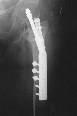 |
|
Figure 11.62. Double plate fixation of an intertrochanteric fracture.
|
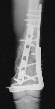 |
|
Figure 11.63.
Reconstruction of a supracondylar fracture of the femur with double plate fixation using a 95° condylar screw with an extension plate laterally and a broad plate anteromedially. Note that the anteromedial plate is shorter than the lateral plate to minimize the stress at the upper ends of the plates. |
stress the fracture to see if micromotion occurs through the fracture
site. If it does, either interfragmentary screw fixation or a second
plate is usually required.
the metaphyseal or epiphyseal portions of the long bones, or they are
designed for the spine or pelvis (Fig. 11.64).
Reconstruction plates have become quite popular since the early 1990s
for the fixation of fractures where bending of the plates in three
planes is necessary to achieve adequate conformity to bone. The most
common sites for this are the distal humerus and the acetabulum and
pelvis.
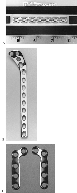 |
|
Figure 11.64. A: The 3.5 mm AO reconstruction plate is used for fibula, radius, ulna, pelvis, and other metaphyseal fractures. B:
AO tibial lateral buttress plate for fixation of fractures of the tibial plateaus. The plate is thick in the diaphyseal portion and thin in the metaphyseal section. C: An AO miniplate for small bones. (Courtesy of Synthes, Paoli, PA.) |
three planes. Make bends in the plane of the plate before twisting or
bending vertically to the plane of the plate. Apply a malleable
template to the bone first. Use the template to determine the bends on
the plate. Bending is less injurious to the plate and easier with the
use of special bending presses. Bending is more accurate and safer if
the plate is held by an assistant while the surgeon bends the plate.
Bend in small increments to avoid overbending. Reverse bending of the
plate substantially weakens it and is not recommended. Avoid kinking
the plate. Bends are best distributed throughout the length of the
plate. Make bends between the screw holes. Avoid nicking the plate,
particularly in titanium, where a stress riser effect might occur.
intramedullary nailing is a fixation method superior to plates or
external fixation, because the location of the rod in the
intramedullary canal virtually guarantees proper axial alignment.
Rotational alignment can be ensured with interlocking screws. In stable
fractures, weight bearing is not only feasible but preferable; in an
intramedullary location, nails, unlike plates and external fixation
methods, are load-sharing devices, being subjected to small, bending
loads. Breakage of intramedullary implants is thus minimized.
Intramedullary nails can be placed using percutaneous closed techniques
that minimize soft-tissue dissection, thereby decreasing the risk of
infection. An additional advantage of intramedullary nails is that
removal is often unnecessary. When needed, removal can usually be done
from one end of the nail, using a small incision. Refracture after
removal is uncommon, as no significant stress riser is left in the bone.
that the size of the intramedullary canal may limit the size of nail
that can be used; this limits the bending strength of the nail unless
extensive reaming is performed. Intramedullary nails without
cross-locking screws do not provide as good rotational control as do
plates or external fixation. Intramedullary nails, particularly reamed
nails, interfere with the endosteal blood supply, which makes up to 90%
of the vascular supply to the diaphysis of long bones. This
disadvantage may be minimized by using nonreamed and fluted nails. In
closed fractures, the clinical significance of this disadvantage is
limited, since revascularization from the surrounding muscle takes
place rapidly (84,85 and 86).
In open fractures, particularly of the tibia, in which stripping of the
periosteum and muscle and bacterial contamination occur, the risk of
infection in devascularized bone subjected to intramedullary nailing is
significant. In addition, the techniques for inserting intramedullary
nails by closed technique can be technically demanding.
nailing embolizes marrow contents into the general circulation and
results in microembolization to many solid organs
including the lung. In addition, there are dramatic acute effects on the diaphyseal blood flow (87).
circulation through the copious venous channels in the bone marrow has
been demonstrated in animals (69,101), and embolization has been demonstrated in humans by transesophageal echocardiography and other measures (80,109). The degree of embolization is influenced by various factors (38,51). Nearly all manipulations of the intramedullary cavity cause some increase in pressure; however, Duwelius et al. (38)
have shown the highest pressures with insertion of an awl into the
medullary canal to open it. Reamer design can greatly influence
pressurization of the canal. The lowest pressures can be obtained by
using reamers with a small shaft diameter relative to the diameter of
the cutting flutes, and where the design of the flutes optimizes
depressurization of the canal. The presence of a fracture, slowing the
rate of progression of the reamer down the canal, and increasing the
rotational speed of the reamer have been found to reduce the
intramedullary pressure and amount of embolization. Vent holes in the
distal femur have not been shown to reduce reaming pressures reliably.
have expressed the view that embolization of marrow contents to the
lungs in patients with severe multiple injuries in whom there is
pulmonary compromise or where there has been direct lung trauma is of
concern; therefore, they recommend the use of nonreamed nails in
patients with severe multiple injuries and/or pulmonary compromise.
Many other investigators, however, have shown only transitory changes
in pulmonary function in animals (92,114).
Other investigators in well-designed prospective randomized and
multi-institutional studies have not been able to demonstrate any
significant adverse effects of reamed nailing in multiply injured
patients with and without pulmonary compromise (17,109).
instrumentation and techniques to minimize the amount of marrow and fat
embolization. In addition, using caution in patients with severe
pulmonary trauma or preexisting compromise of pulmonary dysfunction is
wise.
reduced to one third of normal by reaming initially; however, this
stimulates a strong hyperemic reaction that in experimental animals can
reach several times normal by 2 to 4 weeks after fracture (49,76).
Revascularization of the cortex occurs by reversal of the normal
centrifugal blood supply to a centripetal supply coming from the
surrounding muscle and periosteum. Nails that fit the cortex tightly
interfere with this revascularization, so the use of smaller or fluted
nails enhances reestablishment of blood supply to the marrow cavity and
cortex (44,45,114).
In reamed intermedullary nailing, the fracture healing process is
dependent on revascularization of the diaphysis from the surrounding
soft tissues; therefore, reamed nailing is potentially more dangerous
to bone, particularly if infection intervenes and the soft-tissue
envelope is compromised. The hyperemic response in the bone is echoed
by increase in the blood flow to all the soft tissues of not only the
injured leg but the contralateral extremity as well (4,6).
In open fractures of the tibia with exposed bone, muscle flap coverage
of a devascularized cortex has been shown to be important to
revascularization and bone union (88,89,95). The hyperemic response to renailing, however, leads to high rates of union in the tibia and femur reported up to 98% (16,22).
This has led to arguments about whether reamed or unreamed nailing is
the best procedure for diaphyseal fractures. Schemitsch et al. (93,94)
showed no difference between these two types of nailing in an animal
model, from the standpoint of the vascular profusion of the bony callus
formed at the fracture site at up to 12 weeks and in the strength of
union of the callus. On the other hand, studies by this same research
group showed that, in a canine fracture model, overall tibial blood
flow was reduced by 63% with limited reaming and 83% with full reaming.
These data suggest that in severe open fractures, in particular of the
tibia, the best of all worlds may be achieved by gentle, limited
reaming to provide maximum protection to the blood supply but still
allow the use of a 10 mm or larger nail, which provides adequate
mechanical strength for union in the vast majority of cases.
Most other reamed nails are variations of the Küntscher nail, such as
the AO nail, and the various interlocking nails, such as the
Grosse-Kempf (Howmedica, Rutherford, NJ), Klemm (Richards, Memphis,
TN), Alta (Howmedica), Russell-Taylor (Richards), Uniflex (Biomet,
Warsaw, IN), AO Universal (Synthes, Wayne, PA), and others (Fig. 11.65) (40,57,71).
Fluted nails, such as the Sampson (Zimmer, Warsaw, IN), are little used
since the introduction of more advanced locking nails (1).
Reaming provides a precise fit for the nail in the intramedullary
canal, thereby reducing the incidence of nail incarceration and
improving the stability of fixation. Reaming permits the use of larger
nails, which are stronger than smaller ones. A nail with a 12 mm
diameter is 1.25 times stronger in bending than one with an 11 mm
diameter.
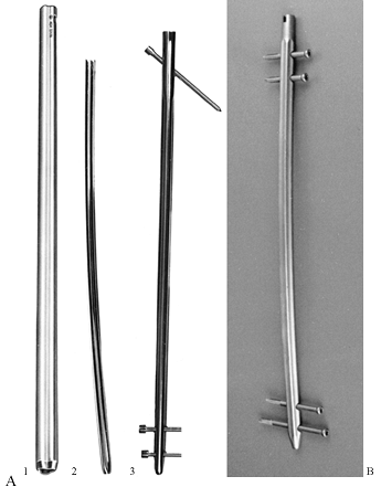 |
|
Figure 11.65. A: Intramedullary nails that require reaming. (1)
A Küntscher nail, designed for open nailing, which is straight, nontapered, and slotted throughout. (Courtesy of Zimmer, Warsaw, IN.) (2) A Küntscher nail, designed for closed nailing, which has a curved, tapered tip, and is slotted throughout. (Courtesy of Howmedica, Rutherford, NJ.) (3) A Grosse-Kempf nail with a curved, tapered tip, a closed section at the upper end, an oblique cross-locking screw proximally, and two transverse cross-locking screws distally. (Courtesy of Howmedica, Rutherford, NJ.) B: Alta intramedullary locking nail for the femur. This is a solid-section, cannulated nail with a hexagonal cross section with smooth flutes to enhance revascularization. It is made of a titanium alloy. Two transverse 5.0 mm diameter cross-locking screws are used distally and proximally, eliminating the need for right and left nails. (Courtesy of Howmedica, Rutherford, NJ.) |
no longer manufactured], the tibia [the Lottes nail (Howmedica, Rutherford, NJ) (67)], the humerus [the Sampson nail (1)], and the forearm [the Sage nail (Smith Nephew Richards, Memphis, TN) (91)] (Fig. 11.66).
Single, nonreamed nails are simple to insert and are associated with
improved preservation of the endosteal blood supply and rapid
revascularization (71,73,84).
Their disadvantages include an increased likelihood of impaction during
driving and, because smaller nails must be used, their relative
weakness, particularly in bending.
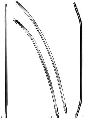 |
|
Figure 11.66. Intramedullary nails designed to be used as single nails without reaming. (Note: illustrations are not proportional.) A: A Schneider nail with a solid, four-fluted cross section and self-broaching ends. (Courtesy of Howmedica, Rutherford, NJ.) B:
A Harris condylocephalic nail that is made from a titanium alloy (Ti-6A1-4V), curved in two planes, and designed for percutaneous, retrograde fixation of extracapsular hip fractures. (Courtesy of Zimmer, Warsaw, IN.) C: A Lottes tibial nail, which is solid, specially curved to fit the tibia, and has a triflanged cross section. These nails are available in 5/16 -inch (8 mm) and 3/8 -inch (9.5 mm) diameters. (Courtesy of Howmedica, Rutherford, NJ.) |
used in groups. The best example is Rush rods, which have been designed
for all the long bones of the body (Fig. 11.67) (90). Ender pins have a similar design (Fig. 11.68) (39,40,73,74).
Multiple Steinmann pins and Kirschner wires can also be used as
intramedullary nails. These devices have all the advantages of
nonreamed single nails, but provide better rotational control; as a
cluster, they are generally stronger than single nails. However, they
are technically more difficult to use and provide relatively poor axial
stability.
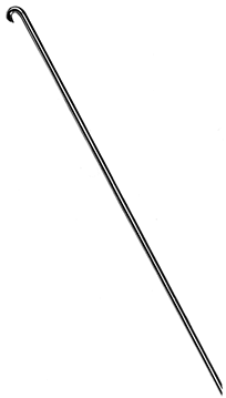 |
|
Figure 11.67. Rush rods are available in four diameters—¼ inch (6.4 mm), 3/16 inch (4.8 mm), 1/8 inch (3.2 mm), and 3/32
inch (2.4 mm)—and in a variety of lengths that are proportional to all the major long bones. Rush rods are solid, with an oblique tip and hooked end that are designed to be inserted percutaneously. These rods must be prebent by the surgeon to obtain three-point fixation in the canal. (Courtesy of Howmedica, Rutherford, NJ.) |
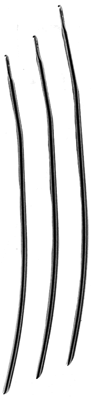 |
|
Figure 11.68.
Ender pins, which are solid with an oblique tip and an eye in a flange at the other end, were originally designed for percutaneous, closed treatment of extracapsular hip fractures. Special sizes are available for the humerus and tibia. They are used in groups. (Courtesy of Howmedica, Rutherford, NJ.) |
published, locking intramedullary nails have gained wide acceptance and
have revolutionized fracture care. The Grosse-Kempf (Howmedica
Rutherford, NJ) (57) and Klemm (no longer manufactured) (60)
nails were the first generation of locking nails. Many new
second-generation designs are available, and they address a wide range
of problems in the femur, tibia, and humerus. Although available,
locking nails for the forearm have not yet gained wide use.
obsolete. The only advantages of nonlocking single nails are their
simplicity and low cost.
addressed by percutaneous fixation techniques. Except for the
Brooker-Wills nail (Biomet, Inc., Warsaw, IN) (Fig. 11.69)
with its flanges, and the expandable tip of the Seidel nail (Howmedica,
Rutherford, NJ), which is used exclusively for the humerus, all current
designs use two or more distal transverse cross-locking screws, as in
the Alta intramedullary rod (Howmedica, Rutherford, NJ) (Fig. 11.65B) (110). Proximal fixation includes inclined screws, as in the Grosse-Kempf nail (Fig. 11.65A); two transverse
screws, as in the Alta (Fig. 11.65B);
and specialized screws through the nail designed to secure fixation in
the femoral head, as in the Russell-Taylor nail (Smith Nephew Richards,
Memphis, TN) or the Alta CFX nail (Howmedica, Rutherford, NJ) (Fig. 11.70).
The Alta nail is designed to have its two proximal cross-locking screws
located just distal and proximal to the lesser trochanter when the top
of the nail is flush with the cortex at its entry hole. This permits
the surgeon to set the nail more proximally to secure fixation in the
femoral neck without having the nail protrude above the tip of the
greater trochanter (Fig. 11.71). This allows fixation of subtrochanteric fractures that include even the lesser trochanter.
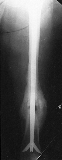 |
|
Figure 11.69.
Brooker-Wills nail fixing a fracture of the femur, AP roentgenogram. This nail is a variation of the Küntscher nail with flanges deployed through slots in the tip of the nail for distal stability. They are deployed internally, and it has an oblique cross-locking screw proximally. With the advent of more advanced cross-locking designs, this nail has disappeared from the marketplace. (Courtesy of Andrew Brooker, M.D., Baltimore, MD.) |
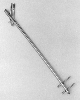 |
|
Figure 11.70.
Russell-Taylor reconstruction nail, a third-generation nail. Proximal locking into the femoral head makes it useful for hip fractures. (Courtesy of Howmedica, Rutherford, NJ.) |
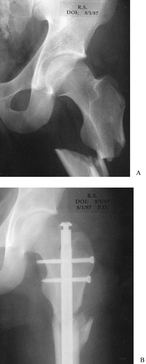 |
|
Figure 11.71. A: Subtrochanteric fracture of the femur at the level of the lesser trochanter. B:
Fracture fixed with an Alta intramedullary nail and two transverse cross-locking screws inserted across the femoral neck. Distal cross-locking screws were used as well. |
unique advantage that the surgeon can combine hip fixation systems with
the intramedullary nail for the fixation of
intertrochanteric–subtrochanteric fractures, and concomitant
ipsilateral fractures of the femoral neck and femoral shaft (Fig. 11.72).
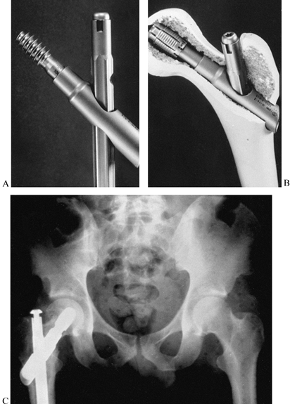 |
|
Figure 11.72. A:
Alta intramedullary nail with rod connector and hip screw used to fix concomitant ipsilateral femoral neck and shaft fractures, as well as subtrochanteric fractures of the femur. B: Alta rod connector in a plastic femur, combined with a hip bolt for fixation in the femoral head. C: Fracture of the femoral neck fixed with an Alta bolt. A rod connector and an intramedullary nail are used to fix an ipsilateral concomitant femoral shaft fracture. (Courtesy of Howmedica, Rutherford, NJ.) |
specialized nails for particular problems have been developed based on
the locking principle. The Zickel nail (117,118) for subtrochanteric and supracondylar fractures of the femur is now obsolete because it is not a fully
cross-locked nail, and the Sage nail (91) for fractures of the radius and ulna has been replaced by plates, again because cross locking is not available.
developed initially in a short design for fixation of intertrochanteric
and some intersubtrochanteric fractures. This nail has been extremely
successful in Europe but has not gained much popularity in North
America. When it was introduced, the principle of overreaming and
sliding the nail in by hand was not appreciated by early users in North
America and this led to an unacceptable incidence of additional
subtrochanteric fractures of the femur. The gamma nail is now available
in a long device that functions like most reconstruction nails, except
that a single locking screw is used in the femoral head and neck.
Nearly every manufacturer now offers a third-generation, so-called
reconstruction nail; in this system, different types of screws are
inserted through the reinforced larger proximal section of the nail up
into the head neck fragment of the femur. When combined with distal
cross-locking screws, these devices enable the surgeon to stabilize
single or combination fractures from the femoral neck to the
supracondylar
area of the femur. Similar design concepts have now been applied to the humerus as well.
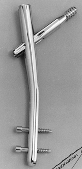 |
|
Figure 11.73.
Gamma nail. This intramedullary device is designed for proximal intramedullary fixation of intertrochanteric and some subtrochanteric fractures. It is available in a long version as well. |
patients with displaced, closed fractures of the lower extremity, who
have unstable fracture patterns and in whom early weight-bearing and
rehabilitation is advantageous. Fracture patterns (Fig. 11.74) are important to consider in making therapeutic decisions (21,22,26,113).
Unless some type of supplemental external protection is used, simple
oblique or spiral fractures are the only fractures that are nearly
always stable after reamed or nonreamed intramedullary nailing without
locking (Fig. 11.74A, Fig. 11.74B). The fracture configurations in Fig. 11.74C, Fig. 11.74D, Fig. 11.74E, Fig. 11.74F and Fig. 11.74G
generally remain unstable with the use of routine reamed or nonreamed
nails, and interlocking nails are required. Noninterlocking nails must
not be used in the latter group of fractures unless special precautions
are taken to prevent shortening and malrotation. Protection for 6 to 12
weeks is often necessary, depending on the fracture configuration.
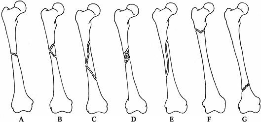 |
|
Figure 11.74. A: Midshaft transverse or short oblique fractures are stable and therefore ideal for closed intramedullary nailing. B:
Midshaft fractures with short butterfly fragments are also stable if there is 50% or greater contact between the proximal and distal fragments. C: Midshaft fractures with large butterfly fragments and less than 50% contact are unstable after routine nailing. An interlocking nail in the static mode should be used. D: Segmental comminution requires statically interlocked nails. E: Long spiral or oblique midshaft fractures may be stable with routine nails. Intraoperative comminution occurs often. It is prudent to insert a locking nail and then lock if necessary. F: Short oblique or transverse fractures within 2–5 cm of the lesser trochanter require a standard interlocking nail or a reconstruction nail. G: Short oblique or transverse supracondylar fractures no closer than 10 cm from the knee are ideal for an interlocking nail. (From Chapman MW. Closed Intramedullary Nailing of Femoral-Shaft Fractures: Technique and Rationale. Contemp Orthop 1982;4:213, with permission.) |
Fractures often have unseen cracks that can progress and lead to
instability. I lock nearly all nails at both ends now. Even in
transverse fractures, I prefer to distally lock the rod first, impact
the fracture with the slap hammer driver, and then lock proximally.
With such good bone contact, immediate weight-bearing is almost always
possible.
femoral shaft in adults and older adolescents is closed intramedullary
nailing (30,113). A
review of the literature comparing closed intramedullary nailing to
open intramedullary nailing, plate fixation, and cast-brace treatment
confirms this view (110).
Closed nailing is reserved for fractures that develop unacceptable
malposition with routine closed treatment or are obviously unstable at
the outset.
are rare. Most of these fractures are nicely managed by closed
technique. The few fractures that do require surgical intervention are
usually best treated by plates and screws, but selected indications for
reamed and nonreamed intramedullary nails are discussed in Chapter 15.
In displaced fractures of the forearm, the best results in adults have
been reported with plate fixation; indeed, the use of intramedullary
nails has been associated with an increased incidence of nonunion and
angulation (5). Locked forearm nails have not proven to be superior to plates.
have shown that nailing of open fractures of the femur can be done with
an acceptable complication rate, provided the benefits of the procedure
outweigh the risks. Although Hansen et al. recommend immediate nailing
of all open fractures of the femur, the infection rate may be lower if
nailing is delayed in type IIIB open fractures. Immediate stabilization
of all femur fractures is important for victims of multiple trauma to
salvage life. Intramedullary nailing is the procedure of choice for
most of these patients.
perform a meticulous irrigation and debridement, including thorough
irrigation of the bone and medullary canal at the fracture site, and
initiate appropriate intravenous therapy as described in detail in Chapter 12
on Open Fractures. In Gustilo grades 1, 2, and 3A fractures, I almost
always carry out locked intramedullary nailing. Since the fracture site
is open, nailing is simplified and the majority of these cases can be
stabilized on a regular operating table
with
the patient in the lateral decubitus position using an antegrade
approach. I leave the traumatic wound open and perform delayed primary
closure at approximately 5 days. It is important to protect the
vascularity of the femur in open fractures, so I use gentle, minimal
reaming and usually an 11 mm nail. In large men, this nail can often be
implanted without reaming. Although the risk of infection is low, this
makes recovery more likely if infection does ensue, as the diaphysis
will be better vascularized and less likely to become a sequestrum. In
isolated high-grade 3B or C open fractures of the femur, which are
exceedingly rare, I also consider immediate intramedullary nailing
using a nonreamed or minimally reamed small nail, as long as the wound
is not highly contaminated and the delay from time of injury to surgery
is not more than 6 hours. Brumback et al. (20)
had an exceedingly low rate of infection after immediate-reamed nailing
of open fractures of the femur and encountered an unacceptable
infection rate only when debridement and nailing was delayed for more
than 24 hours. In the presence of exceedingly severe soft-tissue
wounds, high levels of contamination, and delay in treatment, my
treatment of choice is external fixation with conversion to reamed
intramedullary nailing when the soft tissues have recovered, the wounds
are closed, and there is no evidence of infection. The procedure for
conversion from external fixation to nailing is described above, in the
section on external fixation.
that of the femur. Early studies comparing nonreamed intramedullary
fixation with Lottes nails with external fixation showed comparable
results (67,104). As a
result, when locking nails became available, nonreamed locking nails
quickly became the stabilization method of choice for the vast majority
of open fractures of the tibia as reflected in discussion in Chapter 24 (note the results listed in Table 24.7).
External fixation is reserved for those fractures that are unsuitable
for nailing because of their configuration, or in those that are highly
contaminated and irrigation and debridement has been excessively
delayed, as discussed for the femur. Because of their small size,
nonreamed nails have experienced significant failure rates, with
fracture of screws reported up to 30%, and delayed and nonunion rates
reported up to 20%; therefore, some centers have studied minimally
reamed and fully reamed nails for the fixation of open fractures. This
is discussed in detail in Chapter 24. Recent reports, particularly those from Court-Brown et al. (31), have shown complication
rates in reamed nailing of open fractures to be comparable to those
with nonreamed nails with improved union rates, less hardware breakage,
and fewer malunions.
10-mm-diameter titanium nails, which permits the use of the strongest
5-mm-diameter cross-locking screws (Fig. 11.75).
With this device, fixation is secure and hardware failure exceedingly
rare. A nail this size can be passed unreamed in about 40% of men, and
with the passage of only one or two reamers in the remainder. Women
require somewhat more reaming, so in the smallest I will use a 9 mm
nail.
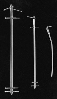 |
|
Figure 11.75.
Alta titanium tibial–humeral intramedullary locking nails. These nails can be used reamed or nonreamed and are available in 6–14 mm diameters. The 10–14 mm diameter nails use a 5 mm cross-locking screw. The 8.25 and 9 mm nails use a 3.7 mm cross-locking screw, and the 6 and 7 mm nails can be locked proximally. Notice the extender and tab, which attach to the proximal end of the nail to enhance proximal cross locking. (Courtesy of Howmedica, Rutherford, NJ.) |
if the fracture is open I much prefer plate and screw fixation as it
better preserves the blood supply to the diaphysis, and injury to the
rotator cuff is avoided.
nailing can be done as soon as practical after injury. However,
evidence suggests that if nailing is done with an open technique, a
delay in nailing of 7 to 10 days may increase the union rate by taking
advantage of the secondary injury phenomenon (25,28,99).
entry site must be directly above the intramedullary canal. Eccentric
entry sites, particularly in the femur and tibia, can result in
incarceration of the nail or comminution. At the proximal end of the
femur, the entry site for reamed nails is in the thin cortex at the
base of the greater trochanter, at the site of its junction with the
superior aspect of the femoral neck (see Chapter 20) (Fig. 11.76).
The entry site on the femur for retrograde nailing is centralized on
the intramedullary canal on both AP and lateral views with the
fluoroscope and distally in the intercondylar notch just posterior to
the articular cartilage and anterior to the origin of the anterior
cruciate ligament (see Chapter 20).
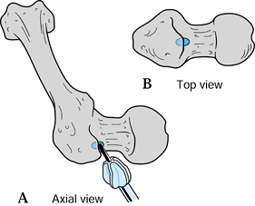 |
|
Figure 11.76. Entry point for the medullary nail. A:
This axial view, seen from the femoral head looking distally, represents the position of the femur in relation to the surgeon. Insert the guide pin at the base of the greater trochanter at its junction with the femoral neck in the region of the insertion of the obturator internus. Note that this entry point is neither on the femoral neck nor on the tip of the trochanter. Drive the pin into the medullary canal with a mallet. B: This direct view of the top of the femur better illustrates the proper location for the entry hole, which is directly above the medullary canal. (From Chapman MW. Closed Intramedullary Nailing of Femoral-Shaft Fractures: Technique and Rationale. Contemp Orthop 1982;4:213, with permission.) |
guide pin and cannulated reamer rather than an awl; this offers better
control and facilitates the use of the fluoroscope to identify the
proper entry site. In the tibia, the most direct route is to split the
patellar tendon and enter the bone just proximal to the tibial
tubercle. To avoid injury to the patellar tendon, some surgeons enter
just medial or lateral to it.
patellar tendon, I used the medial parapatellar approach for a year or
so at the University of California, Davis, Medical Center. Although
nailing can be successfully carried out through this portal, I found
that in the hands of less experienced surgeons it was difficult to
obtain an entry site directly over the medullary canal, resulting in
unacceptable angulation of the nail relative to the longitudinal axis
of the medullary canal. In addition, I have not seen any significant
long-term consequences from splitting the patellar tendon. For that
reason, I now always split the patellar tendon. In the tibia, flexible
nails such as the Ender are usually inserted on the flares of the
metaphysis of the proximal tibia. This technique is discussed in more
detail in Chapter 24.
proximal end. To avoid injury to the rotator cuff, try to locate the
entry site just distal to the insertion of the rotator cuff tendons on
the lateral aspect of the humerus, just below the prominence of the
greater tuberosity, if the nail design permits. Many nails must be
inserted through the cuff. Unfortunately, these result in residual
shoulder symptoms in many patients. The entry sites for the radius and
ulna are discussed in Chapter 16.
is usually used to take advantage of three-point fixation of the curved
nail within the medullary canal. Generally, these nails are inserted
distally through the supracondylar flares of the long bones. Because of
the limited space in the epicondyles of the humerus, the entry site
advised for Ender nails in the humerus is centrally posterior, just
proximal to the olecranon fossa. At entry sites, avoid impingement on
neurovascular structures; to avoid stress risers, do not make the holes
too big. The nails should not be prominent enough to produce bursae or
skin problems.
is reduction of the fracture. Shortly after injury, the hydraulic
effects of edema fluid can cause shortening and rigidity of the limb
segment, which may make fracture reduction extremely difficult. If
nailing is not done before this degree of edema occurs, gentle traction
may be necessary to regain length and alignment gradually as the edema
subsides. If intramedullary nailing is absolutely indicated, it may
even be advantageous to distract the fracture slightly before surgery
to facilitate reduction. With maintenance of length and early nailing,
reduction is usually easy.
achieved by placing the distal fragment in a neutral position, avoiding
tightness of the iliotibial band, which could otherwise result in
shortening and a fixed valgus deformity (Fig. 11.77).
The neutral position is achieved with 15° to 20° of hip flexion, and
with the distal fragment level with the floor in the lateral decubitus
position. It can also be achieved in the supine position. The proximal
fragment is then aligned with the distal one by manipulating it with an
intramedullary nail placed temporarily in the proximal fragment (Fig. 11.78).
The Alta system has a fracture manipulation tool that enhances fracture
reduction and guide-pin placement, and it can also be used to measure
nail length (Fig. 11.79).
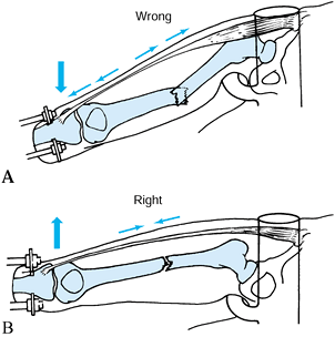 |
|
Figure 11.77. A: In the adducted position, the iliotibial band is tight, shortening the fracture and causing a fixed valgus deformity. B:
A “neutral” position relaxes the iliotibial band, facilitating reduction. (From Chapman MW. Closed Intramedullary Nailing of Femoral-Shaft Fractures: Technique and Rationale. Contemp Orthop 1982;4:213, with permission.) |
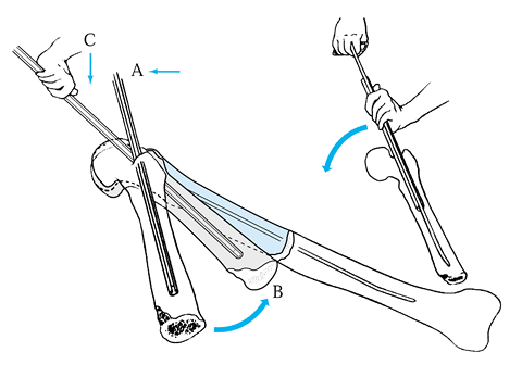 |
|
Figure 11.78. In manipulating the proximal fragment, lateral pressure at point A brings the distal end of the proximal fragment to point B. Downward pressure at point C
then moves the proximal fragment into alignment with the distal fragment. Careful, methodical, and thoughtful technique usually permits quick passage of the guide pin. (Illustration by Beverly A. Kessler, courtesy of LTI Medica, New Scotland, NY, and the Upjohn Co., Kalamazoo, MI, copyright LTI.) |
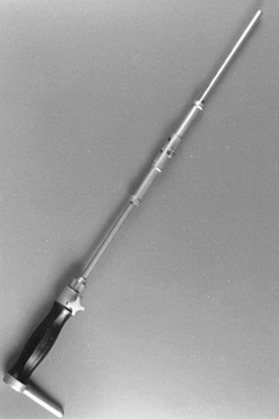 |
|
Figure 11.79.
Alta fracture manipulation tool. This device is used to manipulate the proximal fragment to reduce the fracture, enhance driving the guide pin, and measure the length of the nail. (Courtesy of Howmedica, Rutherford, NJ.) |
the torso may obstruct manipulation of the proximal fragment. Direct
manipulation of the fracture site is often necessary. To avoid
radiation exposure of the surgeon, use manipulation devices such as the
crutch and strap advocated by Küntscher. Use the fracture table for
fractures of the femur and tibia to facilitate reduction. As the tibia
is subcutaneous, direct manual manipulation results in reduction in
most cases.
Reduction is achieved by a combination of manipulation of the proximal
fragment with the nail and direct manual manipulation of the distal
fragment and fracture site.
fracture. Approximate the corners of the cortices of the proximal and
distal fragments at an acute angle and then straighten the fracture
into appropriate alignment. If nonreamed nails are used, this
manipulation is facilitated by placing the nail in the proximal
fragment before manipulation. In reamed nailing, use an incision just
large enough to achieve manipulation; after the reaming guide pin is
placed, close the wound and proceed as for closed nailing. These
techniques are described in more detail in the chapters devoted to
fractures of each long bone.
relationship between the size of the reamers and the nail. A 12 mm
reamer is not necessarily equal in diameter to a 12 mm nail. Because
flexible reamers follow a curvilinear pathway, overreaming is usually
necessary for most nails. Most nails require overreaming from 0.5 to 2
mm over the size of the nail, depending on the type of nail, the
configuration of the fracture, and the canal of the bone.
-
Insert a ball-tipped reaming guide pin across the fracture to the subchondral bone in the distal fragment.
-
Begin with an end-cutting reamer,
generally 8.5 to 9.0 mm in diameter. To avoid overheating and excessive
pressure in the intramedullary canal, push the reamer slowly. -
When substantial cortical bone is being
reamed, clean the reamer frequently to maintain effective cutting
action. On the first pass of the reamer past the fracture site,
visualize it on the fluoroscope to ensure that reaming is progressing
appropriately; thereafter, it is not usually necessary to visualize the
reamer. -
To avoid eccentric reaming and to allow
the reamer head to pass the fracture site, an assistant may need to
manipulate the fracture site gently. -
On withdrawal of the reamer, have an
assistant hold a surgical towel or pad on the end of the guide pin to
prevent its withdrawal along with the reamer. Driving the guide pin
into the solid cancellous bone near the subchondral plate helps to
stabilize the pin. Avoid grasping the guide pin with a bare surgical
glove, as sudden turning of the guide pin will wrap up and rupture the
glove. -
On withdrawal, the reamer will
occasionally “hang up” at the fracture site or at the entrance to the
bone because of the slight shoulder in the design of some reamer heads.
Overcome this by advancing the reamer with full power, then retract it
vigorously. If this is unsuccessful, try pulling the reamer
eccentrically with an Army/Navy retractor while the power is on. -
It is safest to ream progressively in 0.5
mm increments. If the canal is large, after passing the end-cutting
reamer, progress in 1 mm increments until firm contact of the reamer
with cortical bone is established. Thereafter, progress in 0.5 mm
increments. -
In general, avoid overreaming of the
canal by more than 2 mm, as excessive thinning of the cortex may result
in comminution during the drive of the nail. The exception is in
reconstructive procedures and in young patients who have small canals,
where considerable reaming may be required to accommodate a nail of
adequate size. -
Occasionally, the entry hole for the
nail, particularly in femoral nailing, is eccentric and off-line in
relation to the canal. Correct this with the last reamer by pulling it
eccentrically in the direction of the central axis of the canal with an
Army/Navy retractor while reaming the entry hole. This will produce an
oval hole that will permit proper entry of the nail. -
If a reamer breaks or jams, remove it by
pulling it out with the ball-tipped guide pin. Reamers must be powered
by high-torque, low-rpm power sources designed specifically for
intramedullary reaming. -
Avoid excessive pressurization of the
canal by using reamers with large open cutting flutes and
small-diameter shafts. Use a vent hole in the distal femur when
indicated, and advance the reamers slowly using the highest rate of
revolution provided by the power reamer.
bone, including the proximal and distal joints. These help to rule out
irregularities in the bone that might preclude nailing, and they also
aid in the selection of an appropriately sized nail. If a full
complement of intramedullary nails is available, it is usually
unnecessary to measure patients for nail size before surgery unless
they are of unusual stature. If there is any question, obtain AP and
lateral radiographs of the opposite normal limb at a tube-distance of 1
m. Tape a nail of the appropriate size to the side of the limb for
reference, or a radiographic ruler can be used; alternatively, a
Küntscher measuring device—the ossimeter—may be used to measure length
and width (Fig. 11.80). The ossimeter has two
scales, one of which takes into account the magnification caused by the
x-ray at a 1-meter tube distance. In most cases, a nail reaching to
within 1–2 cm of the subchondral bone distally is indicated. In reamed
nailing, the width of nail is better determined by the feel of the
reamers than by radiographic
measurements,
although the approximate size to be used can be determined from
preoperative radiographs. Diameter is critical in nonreamed nails,
especially when a snug fit is anticipated. The radiograph is helpful in
determining nail size before surgery, but, again, the feel of the nail
as it is driven is most important.
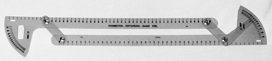 |
|
Figure 11.80.
A Küntscher ossimeter is a Plexiglas measuring device used to measure canal diameter and bone length from roentgenograms taken at a 1 m tube distance. A “real” scale and a special exploded scale (to allow for radiographic magnification) are available. |
determine the proper nail length. A radiograph of the opposite normal
bone with an appropriate-size nail taped to the extremity is quite
helpful.
tibia, and humerus and forearm are now available. The most common types
of interlocking nails use transverse screws distally and oblique, or
transverse screws proximally (Fig. 11.70, Fig. 11.71, Fig. 11.72, Fig. 11.73, Fig. 11.75, and Fig. 11.77).
The guides for proximal cross locking are effective. Never subject
nails to extremely hard driving, as distortion of the proximal end of
the nail may interfere with both proximal and distal cross locking.
Difficulties in passing the proximal cross-locking screw are almost
always due to distortion of the proximal end of the rod or a loose
connection between the nail and the guide. Before driving the rod,
check all connections of the driver and guide.
-
To perform proximal cross locking, lock
the proximal screw guide securely into place. Use the drill sleeve and
an appropriate drill point for drilling. If the drill point contacts
the rod, immediately withdraw it to avoid breakage. -
After drilling, measure the screw length
with the depth gauge. Often this requires fluoroscopy, as it is
difficult to feel the opposite cortex with the depth gauge. If the bone
in the region where the cross-locking screws are being inserted is
nearly round, then screw lengths can be determined by measuring
directly on the fluoroscope monitor. The diameter of the rod is known
(e.g., 12 mm). Have a nonsterile assistant or nurse mark the width of
the rod on a piece of paper placed on the monitor screen and then use
that as a reference to measure the width of the bone at the
cross-locking hole. This is quick, easy, and accurate within 2 mm or
so. It is not reliable when locking on a sloping surface such as the
proximal tibia. -
Insert the screw, taking care to avoid
cross threading the rod in threaded designs. The heads of most cross
screws are quite prominent. Insert them to bring the top of the screw
head flush with the bone of the greater trochanter to avoid
trochanteric bursitis and a snapping iliotibial band, and prominent
screw heads in other locations.
well as those for proximal cross locking due to the flexibility of
these long guides and distortion of the nail. The Alta system offers a
rod-mounted distal cross-locking guide for the femoral, tibial, and
humerus nails. The fluted design of the Alta nails minimizes nail
distortion in rotation and varus and valgus. The rod will bend in the
anteroposterior plane, and this is adjusted for by the guide. It can be
used with percutaneous technique, minimizing exposure to x-rays (Fig. 11.81).
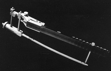 |
|
Figure 11.81.
Alta cross-locking guide for the femur. The guide mounts on the driver for the nail and is used for proximal and distal cross locking. The guide is radiolucent and has a system that facilitates percutaneous screw insertion with minimal use of x-rays. (Courtesy of Howmedica, Rutherford, NJ.) |
based on a stabilizer probe placed at right angles to the cross-locking
screws, which must be inserted down to articulate with the rod through
a separate stab wound and hole drilled in the femur. These have met
with mixed success. Laser light guides that mount on the C-arm head are
used to facilitate free-hand targeting but are not in wide use as they
do not eliminate the need to use x-ray. Guides using detection of a
magnetic field can eliminate the need for x-ray except to verify screw
position and length. They are just now in clinical trials.
-
Position the heads of the C-arm
fluoroscope for a lateral view of the distal end of the rod. Provide
maximal clearance between the lateral side of the limb and the head of
the C-arm. Align the C-arm with the first of the two distal cross
holes. The cross hole to be targeted must be located directly in the
center of the fluoroscope screen, must be perfectly superimposed, and
must be round (Fig. 11.82). Achieving this
alignment can be difficult. It may save time for the surgeon to break
scrub to align the fluoroscope head while the radiology technician
operates the controls of the C-arm. It saves considerable operating
time if all controls on the C-arm are loosened and if the head is moved
into position under direct fluoroscopy. Spot images can also be used
but are much more time-consuming.![]() Figure 11.82.
Figure 11.82.
Lateral fluoroscopic view of the distal screws in an intramedullary
nail. Notice that the hole, which is to be cross locked, is in the
center of the screen and is perfectly superimposed. -
Use a long, very sharp 1/8-inch
(0.3 mm) Steinmann pin or a sharp drill point mounted on a radiolucent
targeting handle, or held in a Kocher clamp to pinpoint the area of
penetration of the bone and to avoid exposing the surgeon’s hands to
the central beam of the fluoroscope. Bring the tip of the pin or drill
point into the fluoroscope image, placing it on the skin directly over
the screw-hole image. Mark the location for the skin incision. -
Make a 1 cm longitudinal incision directly over the
P.372
screw hole down to bone. Insert the pin percutaneously to the cortex of
the bone. Again, bring the tip of the pin into the fluoroscopic image
at an angle to the fluoroscope beam and locate the tip of the pin
directly in the middle of the screw hole (Fig. 11.83).
Once located, carefully tip the pin to place it vertical to the cortex
and directly in line with the fluoroscope head in all planes.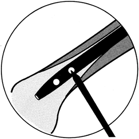 Figure 11.83. Lateral fluoroscopic view of the tip of the pin in proper location before being swung into alignment with the cross holes.
 -
Maintaining this alignment, mallet the
pin into the cortex. It is often possible to insert the pin directly
into the near hole on the rod. -
Once this hole is made, insert the
appropriate-size drill point and, while maintaining alignment with the
fluoroscope head, drill the hole through the rod and the opposite
cortex. -
Remove the power source, leaving the
drill point in place. Verify with the C-arm that the drill point is
directly in the center of the hole. Verify its position on the AP view.
If you plan to insert two screws, leave the first drill point in place
as it is a useful guide to the proper drilling angle for the second
hole. Insert the second
P.373
drill
point with the same technique. Some systems have a hand-held guide that
can be slipped over the first drill point to provide guidance for the
second hole. Repeat the procedure just described. -
Now insert the appropriate-size screw.
Once the initial pin or drill is through the rod and bone, I prefer to
place a drill sleeve over the pin and then do subsequent drilling and
screw insertion through the guide as this avoids getting lost in the
soft tissues. With this technique, radiation exposure is minimized and
only 5 minutes or so are needed to insert each screw.
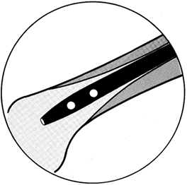
principle for targeting are available but are not widely used, as the
drill points tend to “walk” on the cortex, and the power units are
large and cumbersome.
nailed, the quality of the bone, the stability of the fracture, and
whether an interlocking nail has been used. If a noninterlocking nail
has been used, the patient must be protected against shortening,
angulation, and malrotation until early bone union has occurred.
Because interlocking nails are used in the vast majority of cases, this
discussion will be focused on locked nails.
there is good bone contact over at least a 50% diameter of the cortex
with an adequate-size nail and cross screws for the patient, patients
can be encouraged to bear weight as tolerated using crutches or a
walker. In my experience, the average patient will not attain full
weight bearing before 6 weeks. During this period, the supporting
musculature is quite weak and quadriceps control is poor; therefore,
the patient has little control of the knee. Begin isometric exercises,
followed by progressive resistance exercises, as soon as practical to
reeducate the quadriceps and hamstring and other muscles. In the
meantime, use a knee immobilizer to protect the knee. This can be
discontinued when the patient regains good quadriceps control. In
unstable fracture patterns, particularly where there is extensive
comminution or lack of good bone contact between the major proximal and
distal fragments, limit weight bearing to the weight of the leg until
periosteal callus is seen bridging the fracture site on two views. At
that point, weight bearing can be progressed as the fracture
consolidates.
however, it is usually easier because the patients normally have good
control over their knee. A patellar-tendon-bearing brace or similar
protective orthosis is often useful, particularly in unstable fractures
of the tibia.
unnecessary and the patient can begin immediate gentle range-of-motion
exercises of the shoulder and elbow. Resistive muscle rehabilitation
can usually begin as soon as bridging callus is seen, or earlier in
stable patterns.
malunion is unusual in intramedullary nailing, the surgeon must pay
close attention to avoid it. In simple fracture patterns, establishing
overall alignment of the bone and matching the fracture pattern usually
results in good alignment, particularly since the bone automatically
aligns itself on the rod. In simple fracture patterns, the most common
problem of alignment is malrotation. Verify that the patient’s position
has not shifted on the operating table prior to driving the rod, and be
certain that rotation is comparable to the opposite uninjured
extremity. In bilateral cases, align the first web space of the toes
with the patella and the center line of the hip.
extending into the metaphysis, angular malalignment of the distal or
proximal metaphyseal fragments can occur, particularly since it is
difficult to ascertain overall alignment on the fluoroscope. Inspect
the limb clinically after insertion of the nail. It is occasionally
prudent to get long AP and lateral radiographs immediately after
insertion of the nail to be certain that proper alignment is present
prior to placement of cross-locking screws. Once the nailing has been
completed and the patient is lying in the supine position on the
operating table, carefully examine the operated extremity. It is better
to detect and correct malalignment now than to have to return the
patient to the operating room or to allow malalignment to persist.
cross-locking screws appear to have gone through the nail on an AP
view, but have actually missed the nail. Careful examination with the
fluoroscope after completion of insertion of each screw is essential to
be certain that the screw has in fact passed through both the bone and
the locking holes in the nail. Take final plain films in the operating
room to confirm the fluoroscopic visualization.
due to their increased severity. Delayed union and nonunion in the
femur and humerus is unusual with intramedullary nailing because of the
copious blood supply available from the surrounding muscular envelope.
Other than the deleterious effects of the initial trauma, the most
common
cause
of delayed or nonunion is distraction in the operative site. Brumback
et al. have shown that dynamization of locked nails or removal of
cross-locking screws before nail removal is unnecessary to achieve
union (22).
On the other hand, where the fracture pattern is stable and union is
delayed (no evident callus bridging the fracture site by 12 weeks after
nailing), dynamization may sometimes be indicated. For dynamization to
be effective, it is necessary to remove screws from the end of the nail
farthest from the fracture site. It is important that, when the
fracture site impacts with weight bearing, it becomes rotationally
stable. Dynamization of a straight transverse fracture may lead to
increased rotational instability and progression to nonunion.
nailing of fractures of the femur is less then 1% to 2%, and only
slightly higher in the tibia. The risk of nonunion can be minimized by
utilizing closed techniques, and by ensuring good bone contact,
preferably impaction, and stable cross locking with nails of sufficient
size. If nonunion occurs, most cases are responsive to exchange
nailing. Use closed-technique reaming to a larger nail and then provide
compression across the fracture site with a compression device and lock
the nail in compression. Of course, this is not applicable to fracture
patterns that are axially unstable, where open bone grafting may be
needed. This is discussed in detail in Chapter 26, Chapter 30, and Chapter 31.
nerve at risk is the radial nerve. Although closed nailing techniques
have been advocated for the humerus and used successfully, I have seen
one radial nerve transected by an intramedullary nail or reamers using
closed technique. For that reason, unless there are special
circumstances precluding open nailing, I prefer to expose the fracture
site to ensure that the radial nerve is not in danger, and then to
perform nailing using open technique.
pudendal nerve, which is usually due to inadequate padding or use of
too small a perineal post, plus excessive traction for a prolonged
period of time. If femur fractures are nailed early, within 24 hours,
strong traction is rarely required. If traction is required to reduce a
transverse fracture, apply it only long enough to reduce the fracture,
and then release. Proper technique should prevent the vast majority of
pudendal nerve palsies. Fortunately, nearly all recover without
residual effects.
usually due to excessive traction with the hip in a flexed position and
the knee straight. For that reason, I always keep the knee flexed about
45°, and more if possible, during closed intramedullary nailing of the
femur on a fracture table. The methods described above to avoid
pudendal palsy are also applicable to avoid sciatic nerve palsy. Direct
surgical injury to the nerve is also possible. The exposure used for
closed intramedullary nailing is usually not large enough to allow
formal exploration of the sciatic nerve, but look for the nerve in the
surgical field. In small women with dysplasia of the hip, and in some
Asians, the sciatic nerve rests very close to the greater trochanter
when the hip is flexed 15° to 20° for nailing.
can also occur due to pressure from the traction post on the fracture
table. To avoid this, use a well-padded post of adequate size and avoid
excessive traction.
common peroneal. Paresis can be caused by placing the popliteal bar
against the common perineal nerve and then applying excessive traction
for prolonged periods of time. To avoid problems, use a thigh bolster
that is at least 4 in. in diameter and well padded. Place it under the
distal thigh rather than in the popliteal fascia. The region of the
common perineal nerve near the head of the fibula should always be free
of impingement.
intramedullary nailing are neuropraxias, which recover nicely within a
reasonably short period of time.
screws, wires, or intramedullary nails is indicated. The primary
indication for removal is pain due to the implants, or a request by the
patient for removal for reasons important to her. Another possible
indication is a plate or screw on the diaphysis of a long bone, which
is a stress riser in a patient involved in sports or in an occupation
carrying increased risk for fracture, or increased risk for a fracture
of worse severity because of the presence of the hardware.
morbidity, we advise routine removal of implants, particularly if they
are composed of titanium. The rational is that implants in children
tend to become very tightly integrated to bone and are commonly
overgrown by bone, making subsequent removal exceedingly difficult if
not impossible. There do not appear to be any adverse effects of
leaving current stainless-steel and titanium implants for up to 40
years. However, the long-term effects of leaving these implants in
place for 60–70 or more years is not known; therefore, removal in
children seems advisable.
that their limb feels not as lively as before they received the
implant. This is usually caused by stiffening of the bone segment from
the presence of the implant. Removal of the implant is usually
necessary for the bone to regain its normal flexibility.
original surgical incision. To obtain a nice scar, unless
contraindicated, I usually excise the old wound and use plastic closure
techniques to ensure good cosmesis. Superficial cutaneous nerves and
other structures are more at risk in hardware removal than at the time
of initial surgery, as they are frequently bound down in scar. Look for
these to avoid injury. Occasionally, the pain associated with hardware
is due to nerve entrapment or a neuroma. Treat this at the same time.
-
In removing plates and screws, remove only the bone covering the screw head or plate that interferes with its removal.
-
It is easy to strip screws, making their
removal very difficult. Be certain that the head of the screw is
completely cleaned of bone and that a good-quality screwdriver without
a worn tip is firmly engaged into the screw head. -
Taking a slight turn in the direction of
tightening often breaks any bone adherent to the screw and makes
turning the screw outward easier. If the screw breaks or if broken
screws are encountered, there are screw removal sets available from
several manufacturers. These usually require overdrilling of the screw.
On the other hand, in adults, a broken screw tip in the opposite cortex
may not be in a position that will bother the patient and can be left
in place. -
When removing plates and screws, avoid
creating a stress riser in the bone that might lead to refracture. If
the plate is totally uncovered and does not easily lift off the bone,
place an osteotome beneath the plate and drive along the underside of
the plate parallel to the bone and plate. This usually results in
fairly easy removal. The sharp instruments used for hardware removal
should be from a special set reserved for that purpose, to avoid
damaging high-quality instruments used for initial surgery. -
Once the screws and plates have been
removed, resist the temptation to curet the screw holes. This is not
necessary for healing and simply makes the screw hole wider, thus
increasing the risk of refracture. -
In most cases, the plate will be
surrounded by a ridge of bone that has grown up around the edges of the
plate. Never remove these ridges, as they serve to reinforce the bone
in the early remodeling phase after hardware removal. Nubbins of bone
sticking up from the screw holes can be removed if necessary for
patient comfort.
applicable to nails, as they are removed utilizing closed percutaneous
techniques, and a significant stress riser is not left in the bone. The
major challenge in removing intramedullary nails, particularly in the
femur, is identifying the end of the nail and inserting the removal
instruments. This is particularly a problem in the femur, where a bone
cap commonly forms over the proximal end of the nail. Good surgical
exposure and use of a fluoroscope to locate the top and the
longitudinal axis of the nail is very helpful. A fluoroscope should
also always be used for removal of screws for the same reason. Most
intramedullary nails are now provided with cap screws that prevent bone
growth into the threads of the nail. I like to place a reaming guide
pin down to the top of the nail when there is a bone cap on the nail: I
then use a reamer to expose the top of the nail. It is then fairly easy
to remove the cap screw, insert the rod remover, and extract the nail.
Many intramedullary nailing systems have removal instrumentation that
is different from that used to insert the nail. Be certain to follow
the manufacturer’s recommendations and use the appropriate
instrumentation.
patient is comfortable, he or she can be weaned off crutches to bear
full weight, assuming that the fracture is solidly healed and does not
have a defect in it. Once full muscle rehabilitation has been achieved,
patients can return to sports and occupational activities without
limitations.
needs to be taken because removal of the plate and screws leaves the
bone in a weakened condition with holes that are stress risers. If the
fixation device is confined to the metaphyseal or epiphyseal regions of
the bone, then generally the same guidelines as applied to nails can be
used. In the mid diaphysis, however, assuming that the fracture is
solidly healed, patients can return to functional use of the limb as
tolerated, but they must avoid any activity that would predispose them
to fracture until the diaphysis remodels and the screw holes fill in.
The timing on this depends on the bone, the age of the patient, and the
particular fracture and implant involved.
in a contact sport. I recommend the following as a general protocol:
Typically, the athlete sustains the fracture during the active season
(let us assume the sport is football
and
the fracture occurred in October). If the fracture heals within the
expected time and the callus is adequate to support stress, I permit
the athlete to return to a general conditioning program, avoiding
high-risk activities or contact sports, by 6–8 months after the initial
injury. The football player could then engage in fall practice in
August and return to competitive football in the fall, approximately 1
year after injury. If intramedullary nails are in place, no special
precaution or protective device is necessary.
protective brace is indicated. The athlete should recognize that if a
second severe trauma occurs, a fracture at the end of the plates could
result. If plates are in the lower extremity, on the mid diaphysis of
the femur or tibia, I would not permit the athlete to play contact
sports that season. When that season is over, the time would be
opportune for the removal of the implant, as by then it would be
approximately 18 months since the injury and the bone should be solidly
healed. In the case of plates, I would preclude high-risk activity or
contact sports for approximately 6 months after removal. Then the
patient could gradually return to full-contact activities by
approximately 9 months after implant removal, assuming that the
appearance of bone is satisfactory on radiographs.
scheme: *, classic article; #, review article; !, basic research
article; and +, clinical results/outcome study.
MJ, MacKenzie EJ, Riemer BL. Adult Respiratory Distress Syndrome,
Pneumonia, and Mortality Following Thoracic Injury and a Femoral
Fracture Treated with Intramedullary Nailing with Reaming or with a
Plate. J Bone Joint Surg Am 1997;79:799.
RJ, Reilly JP, Poka A, et al. Intramedullary Nailing of Femoral Shaft
Fractures. Part I: Decision-Making Errors with Interlocking Fixation. J Bone Joint Surg Am 1988;70:1441.
RJ, Uwagie-Ero S, Lakatos RP, et al. Intramedullary Nailing of Femoral
Shaft Fractures. Part II: Fracture-Healing with Static Interlocking
Fixation. J Bone Joint Surg Am 1988;70:1453.
J. Arterial Changes in Experimental Fractures of the Rabbit’s Tibia
Treated with Intramedullary Nailing: A Microangiographic Study. Acta Chir Scand 1960;120:289.
L. Local Arterial Changes Associated with Experimental Fractures of the
Rabbit’s Tibia Treated with Encircling Wires. A Microangiographic
Study. Acta Chir Scand 1962;123:1.
S. Complications of External Skeletal Fixation: Causes, Prevention and
Treatment. Springfield, IL: Charles C. Thomas, 1981.
D, Schlegel U, Perren SM, et al. Intramedullary Pressure in Reamed and
Unreamed Nailing of the Femur and Tibia: An in Vitro Study in Intact
Human Bones. Injury 1993;23(suppl 3):56.
KD, Johnston DWC, Parker B. Comminuted Femoral Shaft Fractures:
Treatment by Roller Traction, Cerclage Wires and an Intramedullary Nail
or an Interlocking Intramedullary Nail. J Bone Joint Surg Am 1984;66:1222.
F. Ueber die Implantation von Elfenbein zum Erzatz von Knochen und
gelenkenden nach Experimentellen und Klinischen Beobachungen. Beitr Klin Chir 1913;85.
DJ, Perkow RL, Gustilo RB. Infection after Intramedullary Nailing of
Severe Open Tibial Fractures Initially Treated with External Fixation. J Bone Joint Surg Am 1989;71:835.
HC, Regal G, Dwenger A, et al. Influences of Different Methods of
Intramedullary Nailing on Lung Function in Patients with Multiple
Trauma. J Trauma 1993;35:709.
ACH, Christie J, Keating JF, et al. The Detection of Fat Embolism by
Transesophageal Echocardiography during Reamed Intramedullary Nailing. J Bone Joint Surg Br 1993;75:921.
FW, Waters CH III. Treatment of Non-unions of Fractures of the Tibial
Diaphysis by Postero-lateral Cortical Cancellous Bone-Grafting. J Bone Joint Surg Am 1980;62:936.
RR, Orsini EC, Mahoney JL, Vershuren R. The Influence of Muscle Flap
Coverage on the Repair of Devascularized Tibial Cortex: An Experimental
Investigation in the Dog. Plast Reconstr Surg 1987;79:946.
RR, Schemitsch EH. Effect of Muscle Flap Coverage on Bone Blood Flow
Following Devascularization of a Segment of the Tibia: An Experimental
Investigation in the Dog. J Orthop Res 1989;7:550.
FP. Medullary Fixation of Fractures of the Forearm. A Study of the
Medullary Canal of the Radius and a Report of 50 Fractures of the
Radius Treated with a Prebent Triangular Nail. J Bone Joint Surg Am 1959;41:1489.
EH, Jain R, Turchin DC. Pulmonary Effects of Fixation of a Fracture
with a Plate Compared with Intramedullary Nailing. J Bone Joint Surg Br 1997;37:984.
EH, Kowalski MJ, Swiontkowski MF. Soft Tissue Blood Flow in Reamed
versus Unreamed Locked Intramedullary Nailing: A Fractured Sheep Tibia
Model. Ann Plast Surg 1996;36:70.
EH, Kowalski MJ, Swiontkowski MF, Harrington RM. Comparison of the
Effect of Reamed and Unreamed Locked Intramedullary Nailing on Blood
Flow in the Callus and Strength of Union Following Fracture of the
Sheep Tibia. J Orthop Res 1995;13:382.
EH, Weinberb JA, McKee MD. The Relative Importance of the
Intramedullary, Intracortical, and Extraosseous Soft Tissue Blood Flow
to the Repair of Devascularized Canine Tibial Cortex. Ann Plast Surg 1997;38:623.
SF, Ferren EL, Self JT. Comparative Mechanical Properties of Various
Kirschner Wire Configurations in Transverse and Oblique Phalangeal
Fractures. J Hand Surg 1988;13A:246.
K, Runkel M, Degrief J, et al. Pathogenesis and Clinical Relevence of
Bone Marrow Embolism in Medullary Nailing Demonstrated by
Intraoperative Echocardiography. Injury 1993;24(suppl 3):73.
GW, Healy WH, Brumback RJ, et al. The Treatment of Fractures of the
Femoral Shaft with the Brooker-Wills Distal Locking Intramedullary
Nail. J Bone Joint Surg Am 1986;68:865.
JW, Rhinelander FW, Stewart CL. Microvascular and Histologic Effect of
Circumferential Wire on Appositional Bone Growth in Immature Dogs. J Orthop Res 1985;3:412.
PR, Sciadini MF, Parker RE. Effects on Pulmonary Physiology of Reamed
Femoral Intramedullary Nailing in an Open Chest Model. J Orthop Trauma 1996;10:75.
MJ, Brumback RJ, Manson PN, et al. Acute and Definitive Management of
Traumatic Osteocutaneous Defects of the Lower Extremity. Plast Reconstr Surg 1987;80:1.