
Editors: Chapman, Michael W.
Title: Chapman’s Orthopaedic Surgery, 3rd Edition
Copyright ©2001 Lippincott Williams & Wilkins
> Back of Book > RESOURCES > COLOR PLATES
COLOR PLATES
 |
|
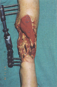
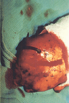
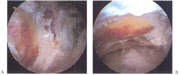
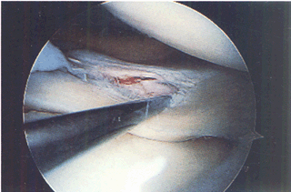
Figure 35.1.
Chronic wound following a tibial 3B injury. Proximal muscle is covered with granulation tissue. There is evidence of desiccated, infarcted tendon and chronic granulation tissue in the base of the wound. This wound required extensive debridement and free flap reconstruction. (This figure is printed in black and white as Figure 1 of Chapter 35.) |
 |
|
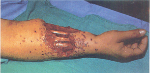
Figure 35.3.
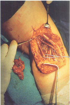
Gunshot wound to upper extremity with soft-tissue defect and exposure of tendons. (This figure is printed in black and white as Figure 3 of Chapter 35.) |
 |
|
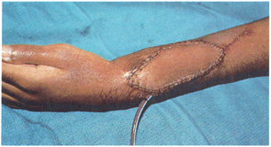
Figure 35.4. C: He subsequently had bony reconstruction with an osteocutaneous fibula transfer. (This figure is printed in black and white as Figure 4 of Chapter 35.)
|
 |
|
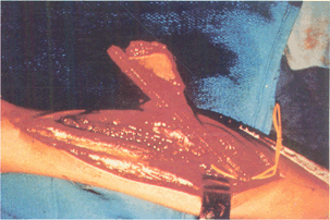
Figure 35.5. B:
An osteocutaneous fibula was taken with a small monitor paddle to ensure vascularity of the bone. (This figure is printed in black and white as Figure 5 of Chapter 35.) |
 |
|
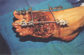
Figure 35.8. Trauma to the lower extremity emphasizing the importance of early coverage. A: Patient was treated with debridement and external fixator. (This figure is printed in black and white as Figure 8 of Chapter 35.)
|
 |
|
Figure 35.12. B: Tumor defect after biopsy and local radiation. (This figure is printed in black and white as Figure 12 of Chapter 35.)
|
 |
|
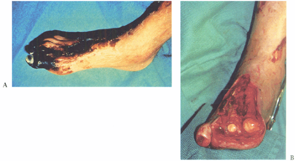
Figure 35.13. A 64-year-old diabetic patient with a dysvascular foot. A: Necrotic foot preoperatively. B: After debridement of tissue. (This figure is printed in black and white as Figure 13 of Chapter 35.)
|
 |
|
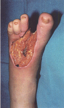
Figure 35.14. Diabetic foot infection. A: Dorsal view. (This figure is printed in black and white as Figure 14 of Chapter 35.)
|
 |
|
Figure 35.26. Venous congested flap treated with leeches. (This figure is printed in black and white as Figure 26 of Chapter 35.)
|
 |
|
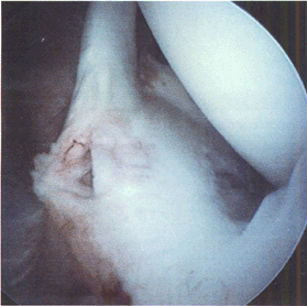
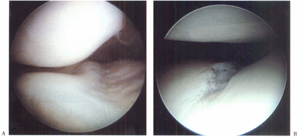
Figure 77.2. Superior labral tear from anterior to posterior (SLAP lesion). (This figure is printed in black and white as Figure 2 of Chapter 77.)
|
 |
|
Figure 77.4. Localizing the acromioclavicular joint. (This figure is printed in black and white as Figure 4 of Chapter 77.)
|
 |
|
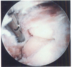
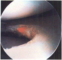
Figure 79.6.
Coracoacromial ligament prior to division with electrocautery (undersurface of acromion is exposed for better visualization). (This figure is printed in black and white as Figure 6 of Chapter 79.) |
 |
|
Figure 79.8. Acromion planed flat when viewed from the posterior portal (A) and from the lateral portal (B). (This figure is printed in black and white as Figure 8 of Chapter 79.)
|
 |
|
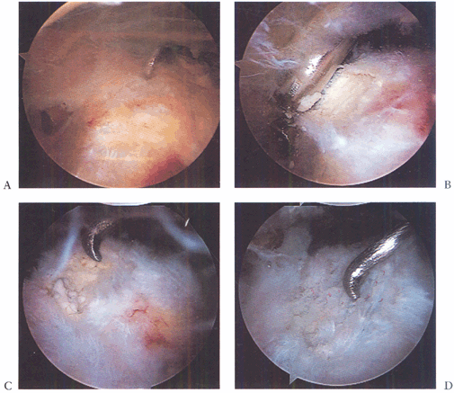
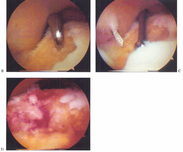
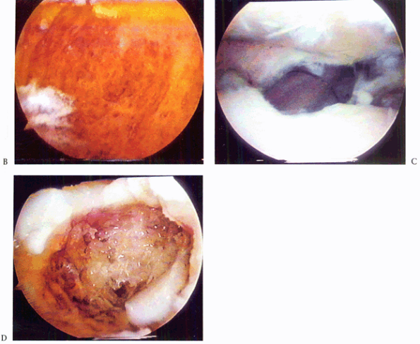
Figure 79.20. Calcific tendinitis. A: Note inflamed area on bursal surface of the supraspinatus, which corresponds to an underlying calcific deposit. B: Unroofing of the calcific deposit by gentle shaving. C: Full extent of the deposit. D: After complete debridement, the tendon remains intact. (This figure is printed in black and white as Figure 20 of Chapter 79.)
|
 |
|
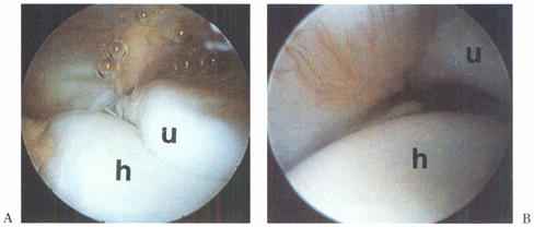
Figure 82.16. A: An arthroscopic view from the anterolateral portal in a right elbow of the humerus (h) and the ulna (u). B:
With valgus stress applied, the increase in space between the ulna and the humerus is seen. (This figure is printed in black and white as Figure 16 of Chapter 82.) |
 |
|
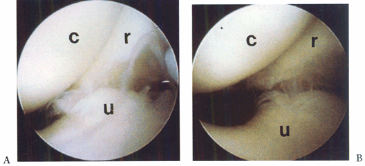
Figure 82.17. Arthroscopic view of the lateral compartment, demonstrating posterolateral subluxation of the forearm bones on the humerus. A: No stress. B: With stress. c, capitellum; r, radius; u, ulna (This figure is printed in black and white as Figure 17 of Chapter 82.)
|
 |
|
Figure 82.18. Arthroscopic view of arthrofibrosis in the anterior compartment. (This figure is printed in black and white as Figure 18 of Chapter 82.)
|
 |
|
Figure 82.19.
Arthroscopic examination of the anterior lateral compartment with extensive inflammatory synovitis. (This figure is printed in black and white as Figure 19 of Chapter 82.) |
 |
|
Figure 84.25. Arthroscopic view of the medial compartment. (This figure is printed in black and white as Figure 25 of Chapter 84.)
|
 |
|
Figure 84.26. Arthroscopic view of the lateral compartment. (This figure is printed in black and white as Figure 26 of Chapter 84.)
|
 |
|
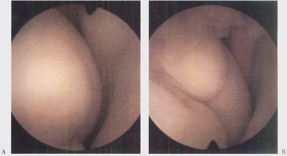
Figure 84.27. Arthroscopic view of the patellofemoral joint from the (A) superolateral portal and (B)
inferolateral portal, demonstrating an injury to the articular cartilage of the trochlear groove. (This figure is printed in black and white as Figure 27 of Chapter 84.) |
 |
|
Figure 84.29. Arthroscopic view of the lateral compartment (A) presynovectomy and (B) postsynovectomy. (This figure is printed in black and white as Figure 29 of Chapter 84.)
|
 |
|
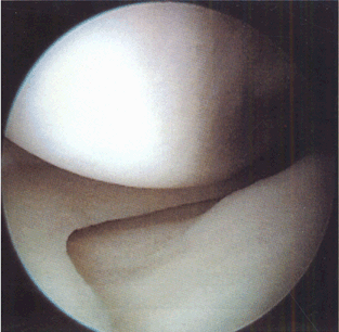
Figure 84.32.
Arthroscopic view of osteochondritis dissecans lesion of the medial femoral condyle. (This figure is printed in black and white as Figure 32 of Chapter 84.) |
 |
|
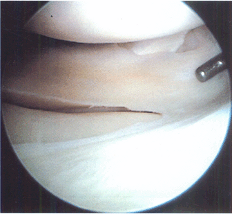
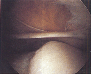
Figure 84.37. Medial plica viewed from superolateral arthroscopic portal. (This figure is printed in black and white as Figure 37 of Chapter 84.)
|
 |
|
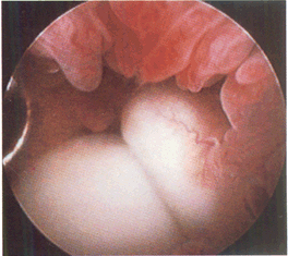
Figure 85.2.
Incomplete tear of the superior surface of the lateral meniscus associated with an anterior cruciate ligament tear. (This figure is printed in black and white as Figure 2 of Chapter 85.) |
 |
|
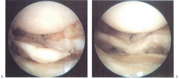
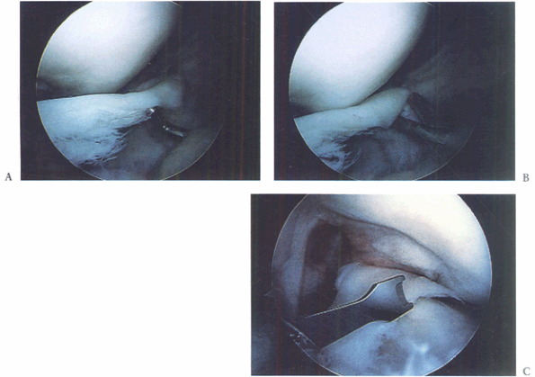
Figure 85.4. A: Displaced bucket-handle tear of the medial meniscus. B: Anterior horn of bucket-handle tear detached. C:
Grasping the resected anterior horn through an inferolateral portal and arthroscopic meniscotome inserted through a transtendon portal to resect the posterior attachment (viewed from inferomedial). (This figure is printed in black and white as Figure 4 of Chapter 85.) |
 |
|
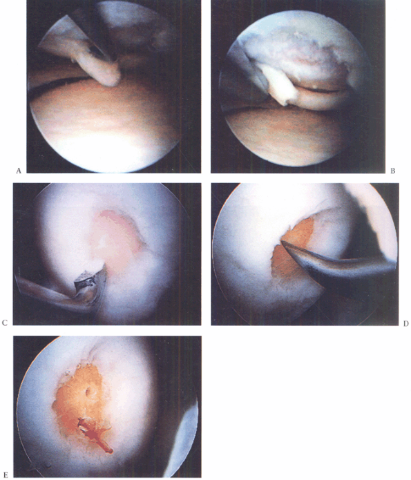
Figure 86.3. Technique for debridement, abrasion arthroplasty, and microfacture. A: Arthroscopic view shows a chondral flap tear on the medial femoral condyle. B:
The unstable flap and unstable edges of the cartilage are debrided. Note that this is a full-thickness defect exposing underlying subchondral bone. C: The debridement is completed by smoothing the edges with a curet. D: An awl is used to punch through (microfracture) the subchondral bone to bring cells into the defect. E: Two microfracture holes, with bleeding from one. (This figure is printed in black and white as Figure 3 of Chapter 86.) |
 |
|
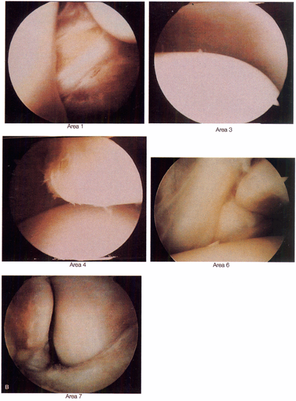
Figure 93.6. B:
Arthroscopic views are demonstrated at positions 1, 3, 4, 6, and 7. (Copyright 1996 by Lippincott-Raven Publishers. From Ferkel RD. Arthroscopic Surgery: The Foot and Ankle. Philadelphia: Lippincott-Raven Publishers, 1996:110, with permission. Illustration by Susan Brust.) (This figure is printed in black and white as Figure 6 of Chapter 93.) |
 |
|
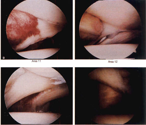
Figure 93.7. B:
Arthroscopic views of points 11, 12, 13, and 14. (Copyrighted 1996 by Lippincott-Raven Publishers. From Ferkel RD. Arthroscopic Surgery: The Foot and Ankle. Philadelphia: Lippincott-Raven Publishers, 1996:112, with permission. Illustration by Susan Brust.) (This figure is printed in black and white as Figure 7 of Chapter 93.) |
 |
|
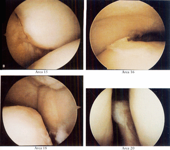
Figure 93.8. B:
Arthroscopic views of points 15, 16, 18, and 20. (Copyright 1996 by Lippincott-Raven Publishers. From Ferkel RD. Arthroscopic Surgery: The Foot and Ankle. Philadelphia: Lippincott-Raven Publishers, 1996:114, with permission. Illustration by Susan Brust.) (This figure is printed in black and white as Figure 8 of Chapter 93.) |
 |
|
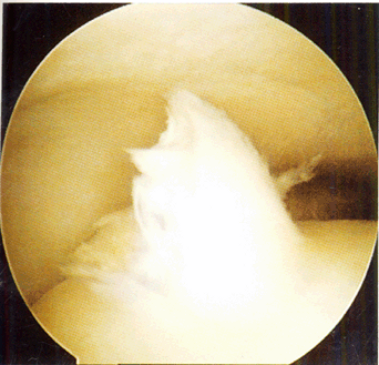
Figure 93.13. Arthroscopic picture of a Stage D osteochondral lesion of the talus. (This figure is printed in black and white as Figure 13 of Chapter 93.)
|
 |
|
Figure 93.14. B: Microfracture of the subchondral surface using an awl. C: Using a drill guide for transmalleolar drilling of the subchondral bone. D:
The result of the above two treatments is a bleeding bone surface providing vascular access for cartilage formation. (This figure is printed in black and white as Figure 14 of Chapter 93.) |
 |
|
Figure 93.15. B: Arthroscopic view from a posterior portal shows the inside of the osteochondral lesion and depth. C: Arthroscopic bone grafting is performed via an osteochondral transplant cylinder. D:
Arthroscopic view from a posterior portal of the bone graft filling the cyst near completion. (This figure is printed in black and white as Figure 15 of Chapter 93.) |
 |
|
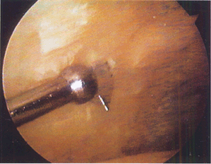
Figure 93.18.
When performing arthroscopic fusion take care to remove all articular cartilage with a combination of instruments. A curved curet is shown here. (This figure is printed in black and white as Figure 18 of Chapter 93.) |
 |
|
Figure 93.19.
A small joint drill guide can be used to drill the guide wires transmalleolar and thus arthroscopically assist in placement of the screws for fusion. (This figure is printed in black and white as Figure 19 of Chapter 93.) |
 |
|
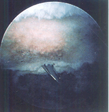
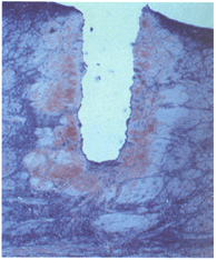
Figure 98.3.
Thermal damage in meniscus after three shots at 1.5 J per pulse at a repetition rate of 1 Hz. Damage extends approximately 350 microns from the edges of the crater (trichrome stain, 40×). (This figure is printed in black and white as Figure 3 of Chapter 98.) |
 |
|
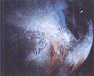
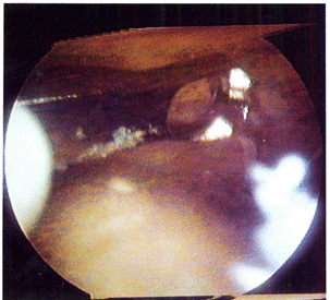
Figure 98.5.
Application of laser energy to the edge of a debrided meniscal tear. The long-term effects of this “annealing” treatment remain controversial. (This figure is printed in black and white as Figure 5 of Chapter 98.) |
 |
|
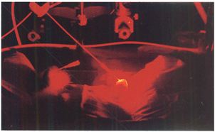
Figure 98.7.
Photochemical treatment of a rabbit model of rheumatoid arthritis. Light delivered percutaneously to the anterior knee joint activates photochemicals that destroy the proliferative synovium. (This figure is printed in black and white as Figure 7 of Chapter 98.) |
 |
|
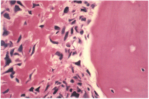
Figure 128.1.
Osteoblastic osteosarcoma showing malignant spindle cells with lacelike osteoid. Trabeculum of normal bone is on the right. (This figure is printed in black and white as Figure 1 of Chapter 128.) |
 |
|
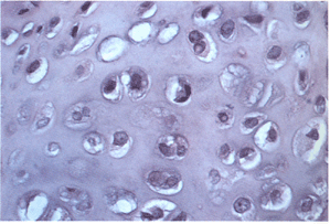
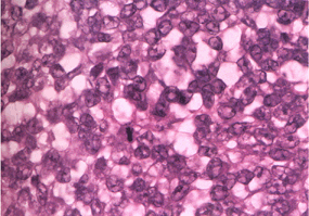
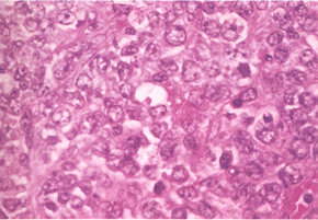
Figure 128.6.
Grade I chondrosarcoma. The lesion is quite cellular, the nuclei are enlarged and irregular, and double nucleated cells are present. (This figure is printed in black and white as Figure 6 of Chapter 128.) |
 |
|
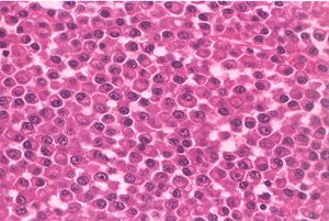
Figure 128.10. Small uniform nuclei with marked hyperchromasia typical of Ewing’s sarcoma. (This figure is printed in black and white as Figure 10 of Chapter 128.)
|
 |
|
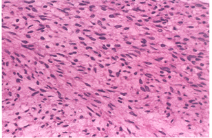
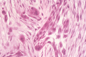
Figure 128.12.
Well-differentiated fibrosarcoma with fascicles of spindle cells without pleomorphism. (This figure is printed in black and white as Figure 12 of Chapter 128.) |
 |
|
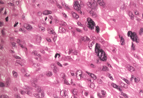
Figure 128.15. High-grade malignant fibrous histiocytoma. There is marked pleomorphism. (This figure is printed in black and white as Figure 15 of Chapter 128.)
|
 |
|
Figure 128.16.
Sheets of plasma cells typical of myeloma. There is abundant pink cytoplasm, and the nuclei are structured eccentrically. (This figure is printed in black and white as Figure 16 of Chapter 128.) |
 |
|
Figure 128.18.
Malignant lymphoma demonstrating proliferation of large cells with irregular nuclei. There is no matrix. (This figure is printed in black and white as Figure 18 of Chapter 128.) |
 |
|
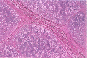
Figure 128.20.
Typical appearance of chordoma. The tumor is divided into lobules with fibrous septa. Tumor cells float in a blue myxoid background. (This figure is printed in black and white as Figure 20 of Chapter 128.) |
 |
|
Figure 128.22. Clusters of epithelial cells surrounded by fibrosis diagnostic of adamantinoma. (This figure is printed in black and white as Figure 22 of Chapter 128.)
|
 |
|
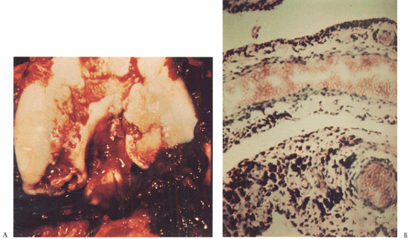
Figure 136.2. A: Photograph of the knee of the patient in Figure 136.1
at the time of open synovectomy a few days after the x-ray studies were taken. There is extensive hyperplastic synovitis with full-thickness erosion of the articular surface of the weight-bearing surfaces of the medial and lateral condyles and the trochlea. This demonstrates the advanced destruction that can occur with chronic hemophilic synovitis despite a relatively benign-appearing x-ray study. B: Photomicrograph of the synovium from this patient showing hemosiderin pigment deposition on the surface taken up by the phagocytic synovial A cells. These cells migrate into the perivascular tissue of the subsynovial layer to return blood products to the general circulation. This patient was in the stage of chronic hemarthrosis, which is easy to understand with dilated venous channels immediately beneath the surface that are easily torn when the fragile, hypertrophic synovium gets caught between the eroded joint surfaces. (This figure is printed in black and white as Figure 2 of Chapter 136.) |