
the contemporary spine surgeon. The primary intention of spinal
instrumentation is to stabilize the mechanically unstable
spine. Gross instability can be secondary to trauma, neoplasm,
infection, inflammatory disease, or iatrogenic removal of anterior or
posterior spinal elements. More subtle forms of mechanical instability
can occur with degenerative processes, such as cervical or lumbar
spondylolisthesis. Spinal instrumentation is used to maintain alignment
and restore stability until solid bone fusion occurs. Although still
considered controversial, the use of spinal instrumentation, in
particular lumbar pedicle screws and anterior cervical plates, in the
treatment of mechanically stable
processes, such as discogenic disease, leads to higher fusion rates.
More recently, a variety of spinal implants have been developed to aid
in reconstruction of the anterior column.
commonly stainless steel or titanium. Stainless steel is strong, is
ductile, and is resistant to notch failure. It is ideal for long
corrective constructs, as used for idiopathic scoliosis. Its high
strength enables large corrective forces to be delivered to the bone.
Ductility allows rods to be bent into the desired shape without having
to be “overbent.” Low notch sensitivity means that a nick or impression
made on the rod surface during contouring would not increase the
chances that it would fail at the notch under cyclic loading. The
disadvantages of steel implants are that they are ferromagnetic, making
postoperative magnetic resonance imaging (MRI) difficult to interpret
because of artifact. There also are possible risks of implant
migration, especially for broken wires or hooks that are near or within
the spinal canal.
not as strong as steel, but this has potential advantages for spinal
fusion. Because the elastic modulus is closer to that of bone (compared
with steel), titanium implants allow more load sharing of the fusion
mass, which may encourage healing and remodeling. A titanium pedicle
screw may have less tendency to loosen because of a better elastic
modulus match with bone. These risks remain theoretical, however, with
no study showing better fusion rates or lower loosening rates with
titanium versus stainless steel implants. Titanium has greater notch
sensitivity than stainless steel. In addition, titanium tends to have
“memory” because of lower ductility. Although it still can be
contoured, titanium rods need to be overbent to achieve the desired
shape. For these reasons, many surgeons still prefer to use stainless
steel systems for deformity correction. The major advantage of titanium
is that it is compatible with MRI. Interbody and corpectomy cages, for
the most part, are constructed from titanium for these and other
reasons.
fabrication of spinal implants. Carbon fiber interbody cages have been
developed. Implanted from either a posterior or an anterior approach,
carbon fiber implants are radiolucent, facilitating unobstructed
radiographic assessment of the fusion. They also may allow more load
sharing by the surrounding bone and fusion mass. Bioresorbable
implants, made of such materials as polylactic acid, show future
promise as temporary stabilization devices that disappear over time.
Resorbable anterior cervical and lumbar plates have been used
successfully in the spine. The stability provided by these implants is
questionable, however, because their effect on fusion rate is unclear.
-
Stabilization
-
Deformity correction
-
Reconstruction/replacement
-
Facilitate/enhance fusion (discussed in Chapter 33)
stability. An illustrative example of this use is posterior segmental
instrumentation of an unstable thoracolumbar fracture-dislocation. In
this case, the traumatic injury created mechanical instability by
disruption of the stabilizing ligaments in addition to bone fractures.
After open reduction and alignment,
the
instrumentation provides long-lasting, durable stability to the
destabilized segments. Spinal stabilization can be achieved with the
use of anterior or posterior implants.
Some disorders cause rapidly progressing deformities. These usually are
associated with infectious diseases, such as vertebral body
osteomyelitis. If treated early, these typically kyphotic deformities
usually are quite mobile and easily correctable.
deformities. Idiopathic scoliosis results in coronal and sagittal
deformities that occur over years. The diagnosis usually is not made
until the deformity becomes cosmetically visible. Another example is
the hyperkyphotic deformity of the thoracic or cervical spine
associated with ankylosing spondylitis. In these cases, the abnormal
spinal curvature becomes relatively fixed. To correct fixed
deformities, instrumentation can be used to impart large corrective
forces to the spine.
 |
|
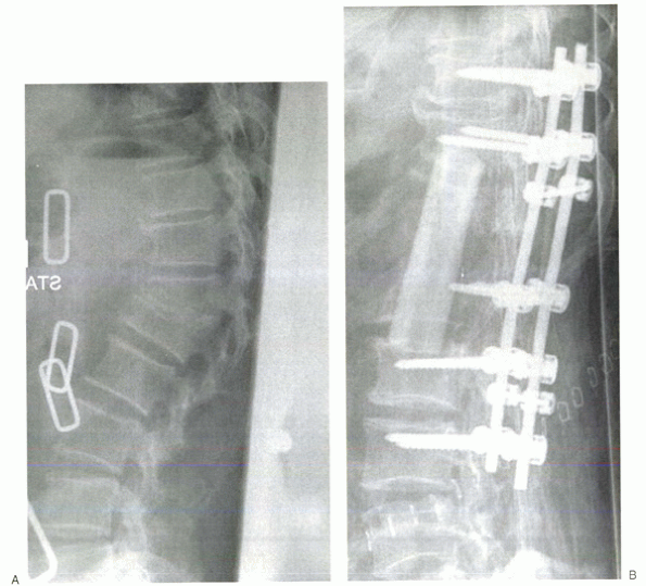
Figure 28-1 (A) Granulomatous infection led to a progressive kyphotic gibbus, intractable pain, and neurologic compromise. (B)
Anterior corpectomy of T12 and L1 was followed by allograft strut interposition to reconstruct the anterior column. Posterior instrumented fusion was performed in a second stage. |
Anterior column reconstruction is necessary when the anterior aspects
of the spine (vertebral body or intervertebral discs or both) are
missing or incompetent. The vertebral bodies can be eroded or destroyed
by infection or tumor (Fig. 28-1A). Highly comminuted burst fractures can result in anterior column insufficiency.
Removal of the vertebral body during surgery necessitates anterior column reconstruction.
of the spine using an implant that is anatomically and biomechanically
similar to the normal spine. The reconstruction would allow segmental
motion just as normal vertebral bodies and discs do. Current methods
necessitate fusion across the reconstructed segments, however. These
requirements define the twofold purpose of anterior column
reconstruction. First, the implant or device must fill the missing gap
between the vertebrae. In doing so, it must sustain the large
compressive loads placed on the anterior spine. Second, it must provide
a conduit for fusion. The ultimate goal of anterior column
reconstruction is to restore and maintain desired height, while
enabling solid arthrodesis between the bridged vertebral segments.
A solid piece of iliac crest autograft can be osteotomized from the
anterior pelvis. The size of the piece is determined by the size of the
spinal defect to be bridged. The bone is tamped into place, interposed
between the upper and lower vertebral bodies. In this example, the
graft is the load-bearing structure and the conduit for fusion. With
time, the graft becomes fully incorporated and replaced by live bone
via creeping substitution.
 |
|
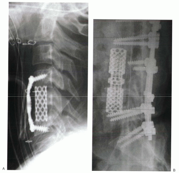
Figure 28-2
Titanium mesh cages can be filled with morcellized, cancellous autograft. They can be used to reconstruct the anterior column after cervical (A), thoracic, or lumbar (B) corpectomy. |
It must be kept in mind, however, that the rate of allograft
incorporation is much slower. For longer defects (anything more than a
disc space), incorporation may not extend much past the contacting ends
of the strut. Creeping substitution after allograft interposition
occurs slowly and incompletely. Regardless, allograft struts provide an
effective and durable method of anterior column reconstruction.
custom fit a defect. The porosity of the mesh facilitates peripheral
bone and vascular ingrowth. The cages can be filled with morcellized
bone graft. The advantage of a cage is that the healthy bone removed
during a procedure, such as a corpectomy of a burst fracture, can be
reused to pack the cage. Additional morcellized autograft can be
removed from the iliac crest through a limited incision and without the
large defect created by structural iliac crest harvesting. With this
method, the titanium cage is the weight-bearing device providing
structural anterior column support, whereas the morcellized bone graft
is the conduit for bone fusion (Fig. 28-2). The increased surface of the bone graft also may hasten incorporation, which does not rely on creeping substitution.
placed without the intention of fusing the segments. This procedure
most often is indicated in cases of metastatic tumor in which the
patient’s expected life span is short. Polymethyl methacrylate cement
commonly is used in this way. In a soft doughy state, the cement can be
molded to custom fit the vertebral defect. When hardened, the cement
interdigitates with the exposed end plates and surrounding bone to
maintain its position. Kirschner wires or Steinmann pins inserted into
the end plates can be used to span the defect before cement insertion
to reinforce the construct. With this method of anterior column
reconstruction, immediate stability is provided, despite the lack of
ability for eventual fusion.
implies that bone anchors (i.e., screws, hooks, or wires) are placed at
each site (or many) along the construct. This contrasts with nonsegmental
fixation, which attaches to the spine at only two sites (one upper, one
lower). A classic example of nonsegmental fixation is a Harrington
distraction rod. By using an up-going hook cranially and a down-going
hook caudally, distraction is applied and maintained. Harrington rods
first were used to correct scoliotic deformities (Fig. 28-3).
Later on, with the addition of compressive rods (down-going hooks
cranially and up-going hooks caudally), Harrington instrumentation and
its variations were used to treat a variety of pathologies. Although a
revolutionary step in the world of spinal instrumentation, nonsegmental
fixation rarely is used by contemporary spine surgeons except for the
stabilization of a single motion segment.
compared with other segmental constructs. They offer excellent
longitudinal (compression-distraction), torsional, and sagittal
stability. Hooks are reliant on longitudinal compressive and
distractive forces for their purchase. Although they offer excellent
sagittal stability, they have inferior torsional stability compared
with pedicle screws. Wire constructs can be effective in correcting
deformities by pulling the vertebra to the rod. They offer good
sagittal plane stability; however, they cannot be used to provide
compression or prevent longitudinal collapse of a spinal segment.
Torsional stability also is limited.
 |
|
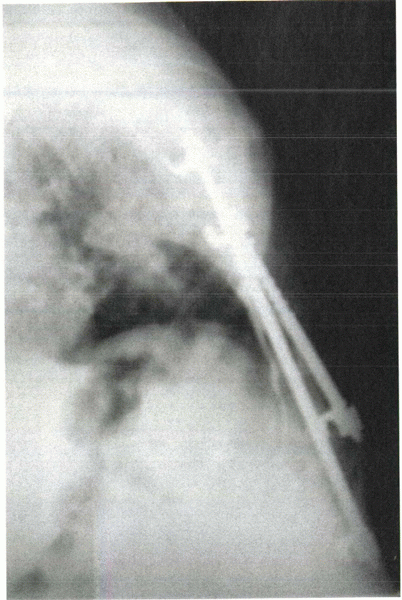
Figure 28-3 Harrington rods rely on distractive forces delivered at only two points. This is a classic example of nonsegmental fixation.
|
of the spine. They can be inserted into virtually any level of the
thoracic and lumbar spine, provided that the screw can be accommodated
by the pedicle. Preoperative measurement of the transverse diameter
determines the maximal diameter of the screw that may be inserted. The
screw should be undersized in relation to the pedicle diameter. In
general, 6-mm or 7-mm screws usually can be accommodated in the lower
lumbar spine. The upper lumbar pedicles (L1 and L2) usually are smaller
than the lower thoracic pedicles (T10, T11, T12) and may accept only a
5-mm screw. The smallest transverse pedicle diameters are found in the
midthoracic region (T4-7, approximately). Counterintuitively the upper
thoracic pedicles (T1-3) usually are larger than their midthoracic
counterparts.
stability, being anchored to the anterior and posterior vertebral
bodies and the pedicle. This is in contrast to segmental hook systems,
which are anchored only to posterior elements (laminae, pedicle, or
transverse process). Because of this
ability,
pedicle screw constructs can be used to deliver large corrective forces
to the spinal column, which are particularly useful in the treatment of
scoliosis, kyphosis, and other deformities. Pedicle screw constructs
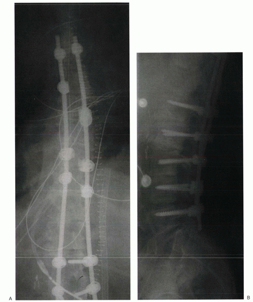
are ideal for stabilizing spinal fractures and dislocations (Fig. 28-4). In contrast to hook or wire constructs, pedicle screws can be used to stabilize laminectomized vertebrae.
normal bone. Disadvantages are that insertion is more technically
demanding than hooks or wires, and fixation in osteoporotic bone is
difficult.
-
A transverse line dividing the transverse process into upper and lower halves
-
A vertical line that is just lateral to the midpoint of the facet joint
located at the junction of the transverse process and the facet joint.
When using this portal, however, the screw must be angled more acutely
medial. The starting portal can be created using a sharp awl, drill
bit, or a small (3-mm) bur tip.
 |
|
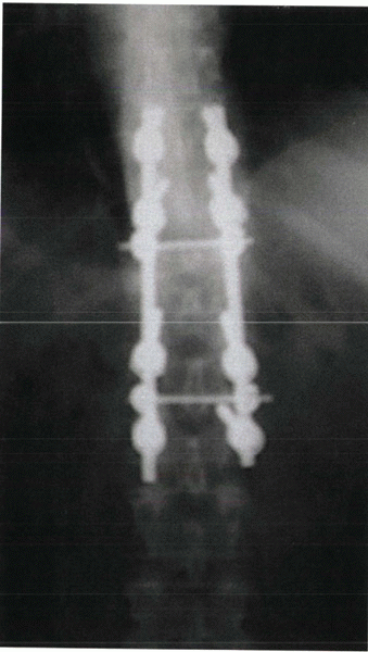
Figure 28-4
Segmental fixation, such as this example of pedicle screws stabilization of a thoracolumbar burst fracture, uses multiple points of fixation. |
system has its own pedicle finder in the set; a small (3-mm) curet also
can be used. The instrument is advanced into the cancellous bone of the
pedicle, using tactile feedback to ensure that the cortex is not
penetrated. If resistance is felt, the orientation of the pedicle
finder should be reconfirmed by visualization of bone landmarks or an
intraoperative radiograph. Many surgeons use fluoroscopy to guide
pedicle screw insertion.
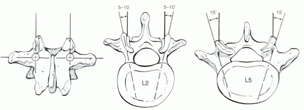
level. At L5, the pedicle usually is angled about 20 degrees medially.
With each cranial level, the medial angulation decreases so that the L2
pedicle is angled only about 10 degrees medially. Although these
numbers are useful guidelines, orientation of the pedicle is assessed
best using preoperative computed tomography or MRI.
bone of the vertebral body. The length of the screw can be measured
using this device, which usually has graduated markings for this
purpose. Then the probe is removed. A pedicle feeler can be inserted to
“sound” the walls of the pedicle to detect cortical perforations. The
hole is tapped, and the screw is inserted. Final screw position can be
confirmed by radiograph.
cortical integrity and screw positioning. Electrical impedance
measurement by directly stimulating the screw with a specially designed
probe can be helpful. Low impedance suggests that the screw has
penetrated the pedicle borders. Other investigators have developed
methods of electrically testing the pedicle hole before screw
insertion. The use of image guidance may increase the accuracy of
pedicle screw insertion, particularly in cases of abnormal or anomalous
anatomy. The use of either image guidance or intraoperative fluoroscopy
usually is needed in revision cases if the anatomic landmarks are
unclear.
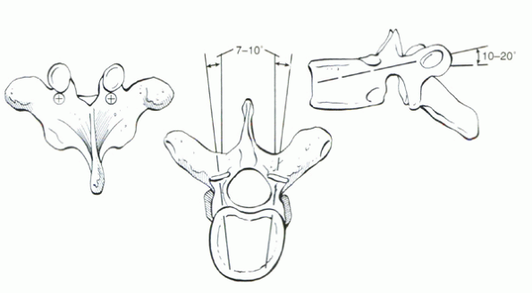
same, the landmarks for thoracic pedicle screws are slightly different
than in the lumbar spine. The starting portal is located at the
junction of the transverse process and the inferior articular process.
In contrast to the lumbar spine, it is aligned with the superior border
of the transverse process (Fig. 28-6).
10 degrees. They also can be quite small, in particular at the T4-7
levels. Although 5-mm screws may fit in the lower thoracic spine,
smaller diameter screws may be safer to insert at more cranial levels.
As in the lumbar spine, preoperative planning using axial computed
tomography or MRI is crucial.
thoracic pedicle and adjacent rib together as the “effective pedicle
width.” In this method, the screw is inserted more laterally,
intentionally perforating the lateral pedicle cortex, but still being
contained by the adjacent cortex of the rib.
This method necessitates more medial angulation to avoid lateral vertebral body perforation.
 |
|
Figure 28-5 Entry site and screw orientation for lumbar pedicle screws.
|
remain an effective and versatile method of stabilizing the spine.
Hooks can be anchored onto the laminae, pedicles, or transverse
processes. Hooks can be placed to create “claws,” which act as
independently stable fixation regions at the cranial or caudal aspects
of a construct (Fig. 28-7). Although Harrington
rods rely on distraction (or compression) across the entire construct,
segmental hook fixation with claws can be used to deliver varying
amounts of compression/distraction precisely at individual vertebral
levels. This feature is particularly helpful to enable
three-dimensional correction of scoliosis.
 |
|
Figure 28-6 Entry site and screw orientation for thoracic pedicle screws.
|
than pedicle screw insertion. Disadvantages are that hooks are an
intracanal, space-occupying device that have the potential for neural
compression.
the ligamentum flavum is released from the inferior border of the
lamina using a small, sharp curet. Next, a Kerrison rongeur is used to
remove a small amount of the lamina to create a rectangular notch.
Careful attention to avoid intrusion into the spinal canal must be paid
to avoid neurologic injury. A trial hook can be used to ensure that the
final implant will seat properly. When inserting the hook, the tip of
the implant should be walked along the bone, keeping contact
with
the undersurface of the lamina at all times. Gentle tapping of the end
of the hook inserter facilitates final seating of the implant.
 |
|
Figure 28-7 Hook constructs are effective means of segmental fixation. (A) They can deliver strong distractive and compressive forces simultaneously to correct spinal deformities. (B)
Although some surgeons still use hooks in the lumbar spine, most prefer to anchor long constructs with multiple pedicle screws in the lumbar vertebrae. |
the ligamentum flavum is released from the superior aspect of the
laminae. Because of the shingle-like overlap of the upper lamina over
the lower lamina, more bone removal is necessary than for up-going
hooks, which are interposed between the laminae. A small portion of the
inferior border of the cranial lamina is removed to gain access to the
interlaminar space. Then a
rectangular
notch can be cut into the superior aspect of the lower lamina. The hook
trial is placed, walking it along the bone surface. The final implant
is tamped into place. Hooks are often loose and wobbly until the
construct is assembled and tightened; they can be dislodged easily.
point, they can be placed only in an up-going fashion. The facet joint
inferior to the pedicle (e.g., T6-7 joint for a T6 pedicle hook) is
exposed. The articular capsule is removed with a curet. A hook trial is
inserted into the facet joint, walking it along the anterior surface of
the inferior articular process of the upper vertebrae. The hook trial
is advanced until the U-shaped end straddles the inferior surface of
the pedicle. Then the final implant is tamped into place.
spine, the spinous processes and interspinous ligaments are removed.
The bone can be salvaged for use as autograft. This maneuver allows
full exposure of the posterior border of the laminae. Next, the
interlaminar space is identified. The ligamentum flavum is released
from the undersurface of the laminae but not removed. A flat, angled
instrument, such as a Woodson elevator, is used to release the
remaining soft tissues underneath the laminae within the midline.
Although this maneuver is “blind,” it is crucial to keep the instrument
in contact with the surface of the bone at all times to protect the
underlying neural structures. After a midline tract has been created,
the blunt end of a looped wire is passed from caudad to cranial. If
braided cables are used, the malleable leader is used to pass the wire.
When the loop is visualized at the superior aspect of the lamina, a
small nerve hook can be used to pull the wire through. After all wires
have been placed, rods are cut and contoured. The wires are tensioned
to the rods in sequential fashion depending on the surgical indication.
the least expensive method of posterior segmental spinal fixation. They
also may have biomechanical advantages over pedicle screws in
osteoporotic bone (because the anterior aspect of the laminae are least
affected by bone density losses). Disadvantages are that wire passage
can injure the neural elements, and multiplanar stability is limited.
instrumentation finds its roots in scoliosis surgery. In the 1960s,
Dwyer developed anterior vertebral body screws that were connected by a
tensioned wire. In later systems, the tensioned wire was replaced by a
rod that could be locked rigidly to the screws. This change allowed
better rotational control and correction. As the applications for
anterior instrumentation were broadened to include stabilization of
fractures, anterior plates were developed. Plates were fixed to the
lateral aspect of the vertebral body by coronally oriented vertebral
body screws. Initial plate designs allowed only static interlocking.
Later, plates with oval holes and compression devices allowed the
graft/strut to be compressed and “locked in” after insertion.
Subsequent revisitation to the rod/screw concept resulted in
development of the Kaneda system. This is a cross-linked, double-rod
system that includes a vertebral body staple through which the screws
are inserted (to act as a washer). Cadaver biomechanical studies have
shown the Kaneda system to be among the strongest constructs for
anterior spinal stabilization.
should be performed. The segmental artery, located in the mid aspect of
the vertebral body, should be ligated and subperiosteally reflected to
avoid injury during hardware insertion.
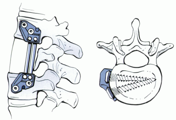
longitudinally and transversely within the vertebral body. Optimal
orientation of the screw is parallel to the adjacent end plates in the
coronal plane (Fig. 28-8). After a starting
hole is created with an awl or small bur, a bicortical hole is drilled.
Penetration of the far cortex must proceed carefully so as not to
injure major visceral or vascular structures. In some cases,
circumferential subperiosteal exposure of the vertebral body enables
one to palpate the contralateral side of the bone. The hole is tapped,
and the screw is inserted.
inserted into each vertebral body. The first screw is inserted within
the posterior aspect of the vertebral body, angled slightly anterior to
avoid the spinal canal. It is crucial to place the screw parallel to
the end plates to facilitate fixation to the rod or plate.
actually a bolt. The bolts are placed first into the cranial and caudal
vertebral bodies. The plate is attached to the bolt with a locking nut.
The anterior screw hole is drilled through the plate. The use of a
guide is helpful in directing the screw about 15 degrees posterior,
creating a triangular construct to improve bony purchase. The
bolt-plate-nut complex creates a fixed-angle device.
is tamped into the mid-vertebral body. The screws are inserted into the
bone through the staple. The vertebrae can be distracted or compressed
through the screws before, during, and after strut or cage insertion.
The rods are inserted into holes in the screw heads and secured.
Cross-linking greatly enhances the mechanical stability of the system.
relatively low profile. Smaller plates have been designed for use in
the upper thoracic vertebrae. The advantage of single-rod systems is
ease of application, especially when stabilizing multiple vertebral
levels for scoliosis. The advantage of
Kaneda-type, double-rod systems is superior biomechanical stability.
 |
|
Figure 28-8
Diagram depicting optimal placement of anterior vertebral body screws. In this example, the screws are offset in the longitudinal plane to avoid crowding. |
generally provide less stability than double-rod systems. Because they
commonly are used to stabilize spinal fractures, this becomes an issue.
The disadvantage of the double-rod systems is bulkiness, which limits
their use to the lower thoracic and upper lumbar spine. Although
single-rod designs are useful in correcting scoliotic deformities, they
remain a relatively weak fixation method.
to plating methods. These can be used to stabilize a single motion
segment, such as after a discectomy and bone grafting procedure, or
multiple segments, such as after corpectomy and strut placement. The
goal of anterior plating is to provide immediate stability to the
operated segments until bone fusion occurs.
instrumentation. Historically, wires were the first method of fixation.
These can be placed beneath the laminae, beneath the spinous processes,
across the facet, or through the bone of the occiput. More recently,
screws have become a popular method of posterior cervical fixation.
Screws can be placed within the lateral mass, into the pedicle, or
across a joint.
relied on use of structural iliac crest bone graft. Wide strips of
bicortical graft are harvested. Occipital wires are passed between the
inner and outer diploë of the cranium through holes created using a
sharp towel clamp. Sublaminar wires are placed at C1, C2, or both, in a
similar manner as described earlier. Wires are passed through drill
holes within the upper and lower portions of the graft. Tightening of
the wires to the graft provides stabilization and a fusion conduit.
Additional morcellized bone graft can be placed along the decorticated
posterior elements of the occiput and cervical laminae. In cases of
instability, a halo fixator should be placed. Techniques of more rigid
internal fixation of the occipitocervical junction can obviate the need
for postoperative halo immobilization. They allow better correction of
deformities, and device contouring enables more precise control of head
position. Optionally, occipital and sublaminar cervical wires also can
be fixed to rods or a Luque rectangle so that stability does not depend
entirely on the integrity of the bone graft strips.
The location of occipital screws should be considered. The central
region centered at the external occipital protuberance has the thickest
dimensions. Unicortical screws placed in this area have equivalent
pull-out strength as more laterally placed bicortical screws. Many
fixation systems take advantage of this fact by enabling screw
placement within this central region.
designed implants can be used to stabilize the craniocervical junction.
With the rising popularity of lateral mass screw-rod fixation, hybrid
plate-rod systems have been developed (Fig. 28-9).
These designs incorporate the advantages of lower profile plating at
the occiput (less soft tissue prominence and irritation) and polyaxial
screws in the lower cervical spine. These systems are ideal for
extended multilevel occipitocervical fusions. Regardless of the method
of fixation, the amount and quality of graft and adequate decortication
of the bone surfaces are crucial in achieving solid fusion.
 |
|
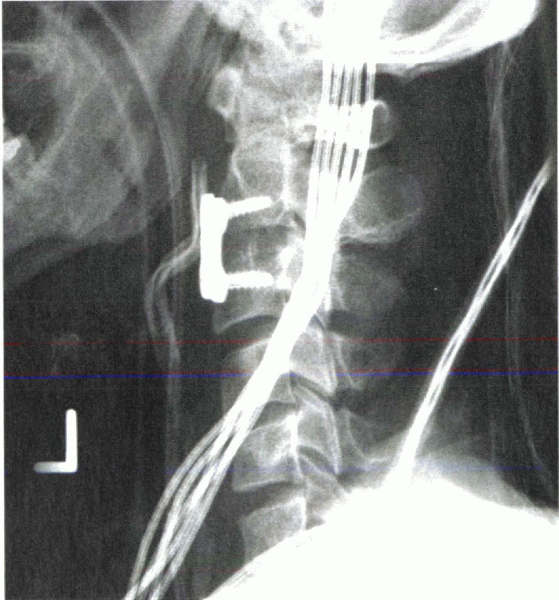
Figure 28-9
Newer methods of occipitocervical fixation use a rod-plate system. The plate portion allows low-profile fixation to the occiput. The rod portion enables the use of polyaxial lateral mass screws in the cervical spine. |
incompetence of the transverse (dens to C2) and alar (dens to cranium)
ligaments. This incompetence can occur from trauma, inflammatory
disease, or congenital/developmental disorders. Atlantoaxial
instability also may result from odontoid fractures, nonunions, or os
odontoideum. Fusion of C1 to C2 is the usual surgical treatment.
Stabilization of the atlantoaxial joint facilitates solid fusion.
passed beneath the posterior C1 ring. These wires then can be looped
underneath the C2 spinous process. Alternatively a C2 sublaminar wire
can be used. A tricortical or bicortical block of iliac crest can be
placed between or over the decorticated C1 and C2 surfaces. In the
Gallie technique, a notch is cut into the inferior portion of the graft
so that it straddles the superior portion of the C2 spinous process.
Cranially, it lies over the C1 ring. This method is the least stable
method of atlantoaxial fixation. Stability relies on the integrity of
the bone graft. Postoperative halo immobilization is often useful.
between the C1 and C2 laminae. Care must be taken not to avoid
intrusion of the graft into the spinal canal. Sublaminar C1 and C2
wires are tensioned to compress the graft in place. Although more
stable than Gallie wiring, it should not be considered rigid fixation
because supplemental halo immobilization may be required.
of the atlantoaxial junction. They are placed from posteriorinferior to
anterior-superior. The starting point is just superior and lateral to
the medial border of the C2-3 facet capsule. The screw is angled
cranially, placed through the pedicle of C2, to cross the articular
surfaces of the lateral C1-2 facet joints. This technique is highly
technically demanding and relies on high-quality intraoperative
fluoroscopy. The vertebral artery, located within the vertebral
foramen, is in danger of lateral cortical violation. Medial penetration
risks the spinal cord within the spinal canal. Although transarticular
screws provide excellent stabilization, they are not by themselves a
fusion method. A posterior Gallie fusion with wiring should be
performed to effect posterior atlantoaxial fusion. If the laminae have
been removed for neural decompression, morcellized bone graft can be
packed into the C1-2 facet joint with care to protect the exiting C2
nerve root.
pedicle screws into C1. These can be attached to C2 pedicle screws with
a rod. Polyaxial screws are ideal for this application. The starting
point for a C1 pedicle screw is approximately 2 cm from the midline,
aligned parallel to the sagittal plane. In contrast to C1-2
transarticular screws, the starting point for C2 pedicle screws is more
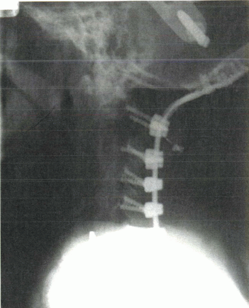
superior and along the lateral aspect of the C2 lateral mass (Fig. 28-10). The screw is angled medially to enter the C2 body. The vertebral artery
(lateral) and the spinal canal (medially) are at risk with screw misplacement.
 |
|
Figure 28-10
In this example of C1-2 fusion, pedicle screws were placed into C2 through a posterior approach. Sublaminar wires secured C1 to a U-shaped rod connected to the pedicle screws and piece of bicortical iliac crest bone graft. |
the upper vertebra. This hole can be started with a small bur and
completed with a sharp towel clip. A wire or cable is passed carefully
through the hole. It then is passed below the caudad spinous process
and tensioned. This method is not possible if a laminectomy is
performed.
been advocated, with plate and rod techniques available today. To
orient the screw head as flush to the plate as possible, the initial
technique, popularized by Roy-Camille, placed the screw perpendicular
to the longitudinal axis, angled laterally about 10 degrees. In efforts
to stay farther away from the vertebral artery (transverse foramen), An
recommended starting the screw more inferior and medial, angling it
cranially about 15 degrees and laterally about 30 degrees. To place a
longer screw in more bone, Magerl advocated aligning the screw parallel
with the facet joint, angling it laterally by 25 degrees.
 |
|
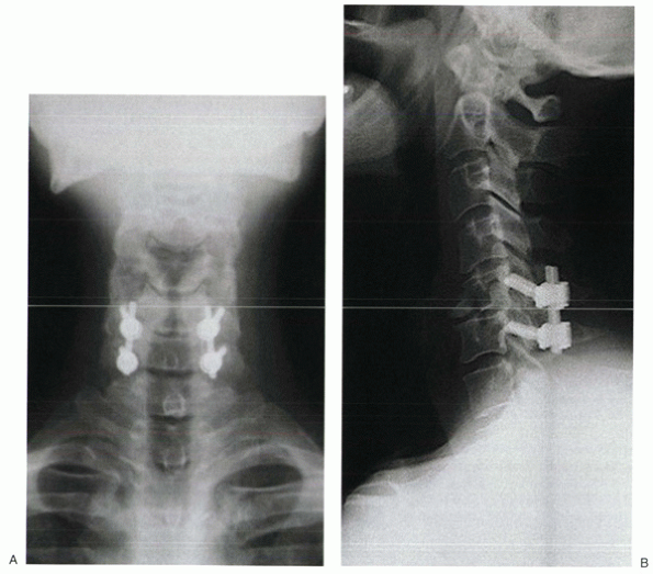
Figure 28-11 Lateral mass screws can provide rigid fixation to the subaxial spine. (A) Note the lateral angulation of the screws on the anteroposterior view. (B) On the lateral view, the screws approximate the plane of the facet joints.
|
placed through the plate. The disadvantage is that the location and
orientation of the screw are determined by the distance between the
holes in the plate. The advantage of screw-rod constructs is that the
screws can be placed at each level first, allowing placement to be
determined by the patient’s anatomy. The screws are connected rigidly
to a rod (Fig. 28-11). Rod contouring can be challenging.
can be used. Screws should be small in diameter because cervical
pedicles are narrow. Placement is highly technically demanding
and
risks injury to the spinal cord and the vertebral artery.
Intraoperative fluoroscopy is not as useful as with C2 pedicle screw
placement so that in most cases insertion is guided primarily by
anatomic landmarks and tactile feel. The pedicle at C2 is dimensionally
larger than the pedicles at C3-7.
variety of spinal pathology. Its use as an adjunct after discectomy and
fusion for degenerative conditions has become increasingly popular,
with advantages of higher fusion rates and possible protection from
anterior graft extrusion. Plates can be used after single-level or
multilevel discectomies. In these cases, screws can be inserted into
each of the stabilized vertebral bodies. After corpectomy, a spanning
plate is used. It is fixed to the cranial and caudal levels. Although a
one-level or two-level corpectomy might be sufficiently stabilized with
anterior plating alone, posterior fixation should be considered after
three or more levels have been spanned.
Screws are angled toward the midline about 10 degrees to 15 degrees.
This angling triangulates contralateral screws to improve bone purchase
and avoids lateral penetration that can endanger the vertebral artery.
unicortical screws. In most cases, however, unicortical screws are
preferred because they avoid intrusion into the spinal canal. Although
bicortical purchase can maintain length of the spanned segments,
fixed-angle unicortical screws may be a safer option to achieve the
same goal. These implants have screws that lock into the plate at the
desired angle. This locking minimizes the chances of postoperative
subsidence of the interbody graft or device into the vertebral bodies.
Although this may be desired in some cases, this feature places greater
stresses on the plate, which can lead to fatigue failure. Most plating
systems are not fixed-angle devices. Almost all have locking
mechanisms, however, by which screw back-out from the plate is
prevented.
 |
|
Figure 28-12
Radiograph of an anterior cervical plate placed after discectomy and fusion. Placement of anterior vertebral body screws into C2 requires adequate proximal exposure, which can be difficult to obtain. |
the vertebral bodies over time. It is believed that this settling may
aid incorporation and fusion. Short plates can be placed at the cranial
and caudal vertebrae after multilevel corpectomies to act as antikick
plates. It is intended that the plates would help prevent anterior
kick-out of the graft, while being nonspanning fixation, to allow
vertical settling. Alternatively, dynamic plates have been devised that
allow subsidence to occur, while still providing additional stability.
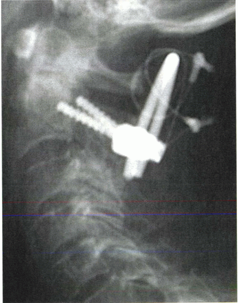
effected by placement of one or two lag screws from the base of the C2
body into the tip of the dens. One or two screws provide adequate
stability. The advantage of this technique is that it is motion sparing
because there is no fusion involved.
cervical spine is performed at the C5-6 level. This approach
facilitates the proper trajectory. After exposure of the anterior
aspect of the spine, the surgeon’s finger is swept cranially to palpate
the C2-3 disc space. A small starting hole can be created at the
inferior lip of the C2 body with a pituitary rongeur. The drill bit is
advanced carefully into the C2 body. After crossing the fracture site
(which should be noted by tactile feel and imaging), the drill bit is
advanced to the tip of the odontoid process. Proper trajectory is
crucial and must be confirmed on anteroposterior and lateral images.
The drill and screw should be contained within bone on all views. If a
single-screw technique is used, the screw is centered within the
odontoid. A supplemental Kirschner wire should be inserted to prevent
rotation of the fragment during screw insertion. Cannulated screw
systems can be helpful in optimizing screw position before drilling.
segment can be provided by translaminar facet screws. These can be
placed through an open incision or percutaneously, using cannulated
devices. The screw is placed from the junction of the spinous process
and the contralateral lamina, through the ipsilateral lamina, and
across the articular surfaces of the facet joint. One of the more
useful applications for translaminar screws is supplemental fixation
after anterior lumbar interbody fusion.
IH. Biomechanical evaluation of subcortical versus bicortical screw
purchase in anterior cervical plating. Acta Neurochir (Wien)
1996;138:167-173.
C, Simon P, Nyssen-Behets C, et al. Perforation of cortical bone
allografts improve their incorporation. Clin Orthop 2002;396: 240-247.
PW, Goel VK, Rogge T, et al. Biomechanical studies on two anterior
thoracolumbar implants in cadaveric spines. Spine 1999; 24:213-218.
U, Hackenberg L, Link T, et al. Pullout strength of pedicle screws
versus pedicle and laminar hooks in the thoracic spine. Acta Orthop
Belg 2001;67:157-163.
PC, Werner RW, Glisson RR. A biomechanical analysis of spinal
instrumentation systems in thoracolumbar fractures: Comparison of
traditional Harrington distraction instrumentation with segmental
spinal instrumentation. Spine 1985;10:204-217.
M, Schmidt R, Claes L, et al. Posterior atlantoaxial fixation:
biomechanical in vitro comparison of six different techniques. Spine
2002;27:1724-1732.
R, Maybee J, Transfeldt E, et al. Experimental pullout testing and
comparison of variables in transpedicular screw fixation: A
biomechanical study. Spine 1990;15:195-201.