
Editors: Koval, Kenneth J.; Zuckerman, Joseph D.
Title: Atlas of Orthopaedic Surgery: A Multimedia Reference, 1st Edition
Copyright ©2004 Lippincott Williams & Wilkins
> Table of Contents > Section II – Elbow > Chapter 11 – Olecranon Fractures: Tension Band Wiring
Chapter 11
Olecranon Fractures: Tension Band Wiring
Kenneth J. Koval
Fractures of the olecranon are relatively common in
adults. The prominence of the olecranon, its subcutaneous position, and
the attachment of the triceps make it particularly vulnerable to
injury. The articular surface of the olecranon articulates with the
trochlea, with motion allowed only in the anteroposterior plane. These
articulating surfaces provide a major component of elbow stability.
Therefore, intraarticular olecranon fractures have the potential to
disrupt the stability of the elbow joint. This chapter illustrates open
reduction and internal fixation of a displaced olecranon fracture.
ANATOMY
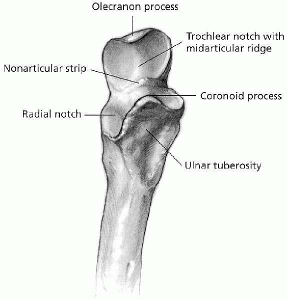
The olecranon, the proximal aspect of the proximal ulna,
is a subcutaneous structure and is, therefore, vulnerable to direct
trauma. Together with the coronoid process, the olecranon forms the
greater sigmoid (semilunar) notch of the ulna, a deep depression that
serves as the articulation with the trochlea (Fig. 11-1).
This articulation allows rotational motion only about the
flexion-extension axis, providing intrinsic stability to the elbow
joint. The articular cartilage surface of the olecranon is interrupted
by a transverse ridge known as the “bare area.” Posteriorly, the
triceps tendon envelops the articular capsule before it inserts onto
the olecranon; the fascia overlying the triceps muscle spreads out
medially and inserts into the deep fascia of the forearm and into the
periosteum of the olecranon and proximal ulna. A fracture of the
olecranon with displacement represents a functional disruption of the
triceps mechanism, resulting in loss of active extension of the elbow.
The ulnar nerve is located on the medial aspect of the elbow, posterior
to the medial epicondyle and medial collateral ligament.
 |
|
FIGURE 11-1. The proximal ulna.
|
CLASSIFICATION
There is no universally accepted classification system
for olecranon fractures. Colton classified olecranon fractures into two
major groups: nondisplaced (type I) and displaced (type II). A type I
fracture has less than 2 mm of separation and no increase in
displacement with flexion to 90 degrees, with the patient able to
extend the elbow against gravity. Colton further subdivided the
displaced fractures into type IIA, avulsion; IIB, oblique and
transverse; IIC, comminuted; and IID, fracture-dislocation.
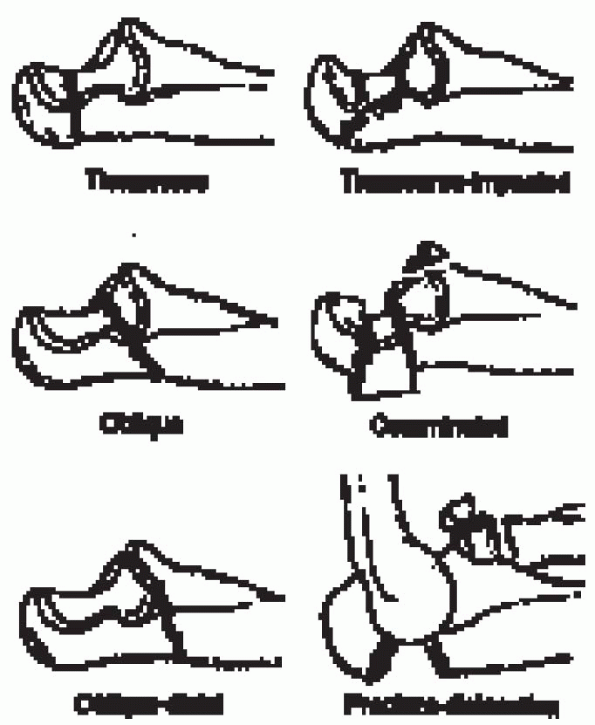
Schatzker classified olecranon fractures as either nondisplaced or displaced (Fig. 11-2).
Displaced fractures can be either extraarticular or intraarticular.
Intraarticular fractures are further divided into transverse, oblique,
comminuted, or fracture-dislocation. Transverse fractures can be simple
or complex (associated with joint depression). Oblique fractures can be
proximal (tip to the midpoint of the semilunar notch) or distal
(midpoint of the semilunar notch to the coronoid process). Comminuted
fractures have multiple fracture lines and may be associated with a
radial head fracture or dislocation.
INDICATIONS
The indications for operative treatment include
olecranon fractures with greater than 2-mm articular displacement or
step-off, injuries with elbow-extensor mechanism disruption,
olecranon fractures with greater than 2-mm articular displacement or
step-off, injuries with elbow-extensor mechanism disruption,
P.114
and open fractures. The inability to extend the elbow against gravity suggests loss of elbow-extensor mechanism integrity.
 |
|
FIGURE 11-2.
The Schatzker classification of olecranon fractures. (From McKee MD, Jupiter JB. Trauma to the adult elbow and fractures of the distal humerus. In: Browner BD, Jupiter JB, Levine AM, eds. Skeletal trauma. Philadelphia: WB Saunders, 1998:1470, with permission.) |
 |
|
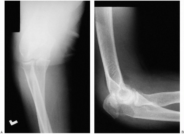
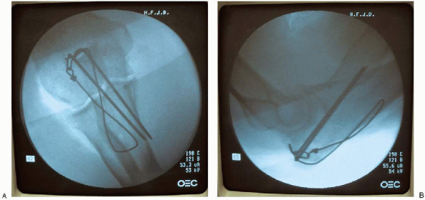
FIGURE 11-3. Anteroposterior (A) and lateral (B) view of the elbow showing a displaced olecranon fracture.
|
The choice of implant to stabilize an olecranon fracture
is based on the fracture pattern and location. A tension band wire
construct can be used for simple and complex transverse fracture
patterns proximal to the coronoid. The tension band wire converts the
extensor force of the triceps to a dynamic compressive force across the
fracture. Beyond the level of the coronoid, however, a tension band
wire construct cannot provide sufficient rotational control. A plate
and screw fixation is used for proximal oblique fractures and fractures
distal to the coronoid.
PREOPERATIVE PLANNING
Radiographic evaluation for an olecranon fracture includes an anteroposterior (AP) and lateral view (Fig. 11-3).
When the olecranon fracture is part of an elbow fracture-dislocation,
traction radiographs may be used to evaluate the injury as well. The
lateral radiographs reveal the extent of the fracture
When the olecranon fracture is part of an elbow fracture-dislocation,
traction radiographs may be used to evaluate the injury as well. The
lateral radiographs reveal the extent of the fracture
P.115
and
the presence of comminution or joint depression. The integrity of the
radial head-capitellar articulation is examined, and subluxation or
dislocation of the semilunar notch from the trochlea is noted. The
anteroposterior radiograph is examined for sagittal fracture lines that
are not well displayed on the lateral view. The integrity of the radial
head-capitellar and semilunar notch-trochlea articulation are also
determined on this view. Comparison radiographs are helpful in complex
fracture patterns.
EQUIPMENT
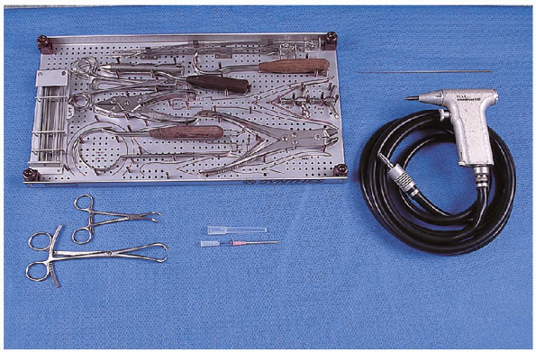
The equipment necessary for tension band wiring of the olecranon include the following (Fig. 11-4):
-
0.062-inch Kirschner wires
-
Wire driver
-
Cerclage wire set
-
14-gauge angiocatheter
-
Large- and small-pointed reduction clamps
-
Small fragment set
PATIENT POSITIONING AND FRACTURE REDUCTION
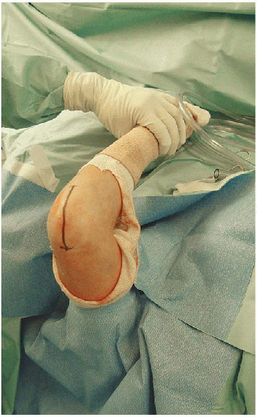
The patient can be positioned supine or lateral. I prefer a supine position with the arm placed across the patient’s chest (Fig. 11-5). The procedure is usually performed under tourniquet control.
INCISION
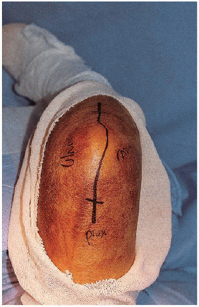
The incision begins distally on the subcutaneous border
of the ulna. It is continued proximally in line with the subcutaneous
border to the ulna of the olecranon area, where it is curved radially
around the tip of the olecranon and then extended proximally in the
midline 3 to 5 cm (Fig. 11-6).
of the ulna. It is continued proximally in line with the subcutaneous
border to the ulna of the olecranon area, where it is curved radially
around the tip of the olecranon and then extended proximally in the
midline 3 to 5 cm (Fig. 11-6).
 |
|
FIGURE 11-4. Equipment for tension band wiring of the olecranon: cerclage wire set (top left tray), 0.062-inch Kirschner wire (top right), large- and small-pointed reduction clamps (2) (bottom left), 14-gauge angiocatheter (bottom middle), and wire driver (bottom right).
|
 |
|
FIGURE 11-5. Supine patient positioning with the arm placed across the chest.
|
APPROACH
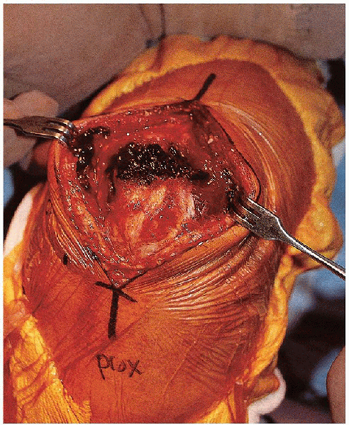
The incision is developed down to the fascia. A subcutaneous flap is elevated over the tip of the olecranon (Fig. 11-7).
The location of the ulnar nerve can be determined by palpation; it is
not usually necessary to isolate and transpose the ulnar nerve.
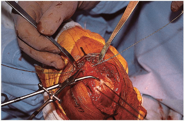
Distally, muscle origins are reflected extraperiosteally as needed.![image]() The posterior aspect of the fracture line is now usually visible. The fracture lines are cleaned of clot and debris.
The posterior aspect of the fracture line is now usually visible. The fracture lines are cleaned of clot and debris. ![image]()
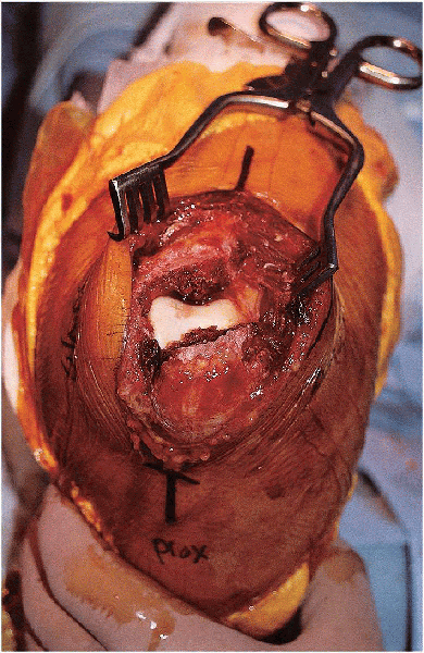
Two millimeters of periosteum is reflected from either side of the
fracture lines to help visualization and fracture reduction.![image]() The joint is visualized by retracting the proximal fragment (Fig. 11-8).
The joint is visualized by retracting the proximal fragment (Fig. 11-8).
The location of the ulnar nerve can be determined by palpation; it is
not usually necessary to isolate and transpose the ulnar nerve.
Distally, muscle origins are reflected extraperiosteally as needed.
 The posterior aspect of the fracture line is now usually visible. The fracture lines are cleaned of clot and debris.
 Two millimeters of periosteum is reflected from either side of the
fracture lines to help visualization and fracture reduction.
The joint is visualized by retracting the proximal fragment (Fig. 11-8).P.116
 |
|
FIGURE 11-6. The skin incision for open reduction of the olecranon.
|
 |
|
FIGURE 11-7. The incision is developed down to the fascia. A subcutaneous flap is elevated over the tip of the olecranon.
|
P.117
 |
|
FIGURE 11-8. The exposed fracture site with retraction of the proximal fragment and visualization of the elbow joint.
|
PROCEDURE
Fracture
reduction begins with elevation of any depressed articular component,
if present. Bone graft is used if necessary to support the depressed
fragments. These reduced articular fragments can be stabilized using
Kirschner wires or small-diameter screws. The main fracture fragments
are then reduced and temporarily held in place with pointed reduction
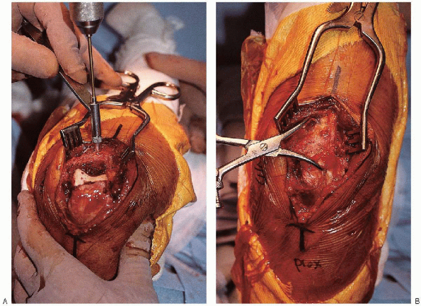
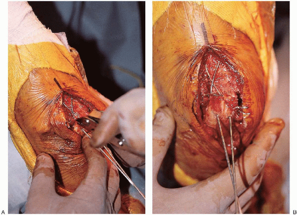
clamps (Fig. 11-9).![image]() Fracture
Fracture
reduction can be facilitated with (a) use of a tenaculum clamp on the
proximal fragment for manipulation, (b) the elbow extended, and (c)
placement of a drill hole in the proximal ulnar shaft to anchor the
distal prong of the pointed reduction clamp.
reduction begins with elevation of any depressed articular component,
if present. Bone graft is used if necessary to support the depressed
fragments. These reduced articular fragments can be stabilized using
Kirschner wires or small-diameter screws. The main fracture fragments
are then reduced and temporarily held in place with pointed reduction
clamps (Fig. 11-9).
Fracturereduction can be facilitated with (a) use of a tenaculum clamp on the
proximal fragment for manipulation, (b) the elbow extended, and (c)
placement of a drill hole in the proximal ulnar shaft to anchor the
distal prong of the pointed reduction clamp.
P.118
 |
|
FIGURE 11-9. A drill hole is made in the in the proximal ulnar shaft (A) and a pointed tenaculum clamp used to provisionally stabilize the fracture reduction (B).
|
 |
|
FIGURE 11-10.
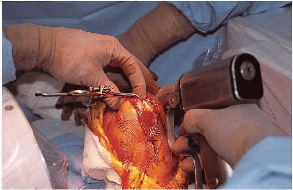
Following fracture reduction, two parallel 0.062-inch Kirschner wires are inserted from the tip of the olecranon, across the fracture, and out the anterior cortex of the distal fragment. |
P.119
 |
|
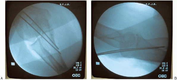
FIGURE 11-11. Anteroposterior (A) and lateral (B) radiographs verifying implant position.
|
The
fracture reduction is then verified by visual inspection and
fluoroscopic evaluation. Once satisfied with the fracture reduction,
two parallel 0.062-inch Kirschner wires are inserted from the tip of
the olecranon, across the fracture and driven out the anterior cortex
of the distal fragment (Fig. 11-10).![image]() Engaging the anterior cortex may diminish pin migration. The wire position is checked fluoroscopically (Fig. 11-11),
Engaging the anterior cortex may diminish pin migration. The wire position is checked fluoroscopically (Fig. 11-11),
and the wires are then backed out to anterior cortex to prevent
excessive anterior soft tissue penetration when the wires are fully
seated.
fracture reduction is then verified by visual inspection and
fluoroscopic evaluation. Once satisfied with the fracture reduction,
two parallel 0.062-inch Kirschner wires are inserted from the tip of
the olecranon, across the fracture and driven out the anterior cortex
of the distal fragment (Fig. 11-10).
Engaging the anterior cortex may diminish pin migration. The wire position is checked fluoroscopically (Fig. 11-11),and the wires are then backed out to anterior cortex to prevent
excessive anterior soft tissue penetration when the wires are fully
seated.
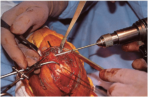
A 2-mm hole is drilled perpendicular to the long axis of the ulna and approximately 3 to 4 cm distal to the fracture (Fig. 11-12). ![image]()
I generally make the distance from the fracture to this drill hole
similar to that from the fracture to the olecranon tip. This drill hole
is approximately halfway between the volar and dorsal surfaces of the
ulna. Placement of this drill hole in an
excessively dorsal location increases the risk for drill hole fracture
when the tension band wire is tightened.
 |
|
FIGURE 11-12. A 2-mm hole is drilled perpendicular to the long axis of the ulna approximately 3 to 4 cm distal to the fracture.
|
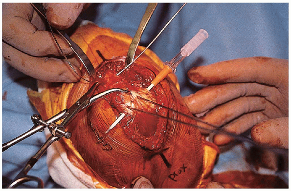
An 18- or 20-gauge wire is passed through this drill hole (Fig. 11-13).
A 14-gauge angiocatheter is then passed deep to the triceps tendon and
the tip of the olecranon, anterior to the Kirschner wires (Fig. 11-14).![image]()
The tension band wire is crossed over the posterior surface of the
olecranon, threaded through the tip of the angiocatheter, and pulled
out through the opposite side of the triceps tendon (Fig. 11-15). Two loops are made in this wire, one knot on each side of the ulna (Fig. 11-16).
A 14-gauge angiocatheter is then passed deep to the triceps tendon and
the tip of the olecranon, anterior to the Kirschner wires (Fig. 11-14).
The tension band wire is crossed over the posterior surface of the
olecranon, threaded through the tip of the angiocatheter, and pulled
out through the opposite side of the triceps tendon (Fig. 11-15). Two loops are made in this wire, one knot on each side of the ulna (Fig. 11-16).
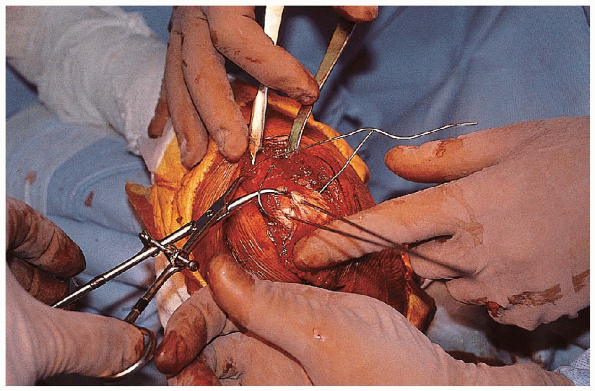
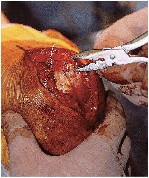
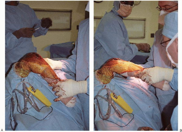
The wire knots are then tightened sequentially with the elbow in extension (Fig. 11-17). ![image]()
This provides more uniform tension to the bone-implant construct. The
knots are cut to a length of 3 to 4 mm, bent down, and buried in the
soft tissue. The Kirschner wires are bent dorsally just past 90 degrees
with a metal suction tip and cut, leaving 3 to 4 mm of wire remaining
past the bend. By using a wire pliers, the K-wires are bent over to 180
degrees (Fig. 11-18) and rotated until the
short portion of the bent wire is anterior. The fibers of the triceps
tendon are split sharply with a scalpel at the entry point of the bent
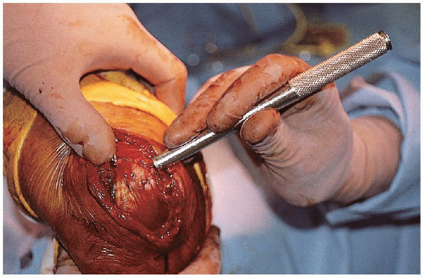
K-wires, and the wires are then seated using a mallet and bone tamp (Fig. 11-19). It
is important to verify that the bent proximal aspect of the wire is
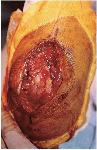
buried under the triceps to minimize the risk of wire backout (Fig. 11-20).
This provides more uniform tension to the bone-implant construct. The
knots are cut to a length of 3 to 4 mm, bent down, and buried in the
soft tissue. The Kirschner wires are bent dorsally just past 90 degrees
with a metal suction tip and cut, leaving 3 to 4 mm of wire remaining
past the bend. By using a wire pliers, the K-wires are bent over to 180
degrees (Fig. 11-18) and rotated until the
short portion of the bent wire is anterior. The fibers of the triceps
tendon are split sharply with a scalpel at the entry point of the bent
K-wires, and the wires are then seated using a mallet and bone tamp (Fig. 11-19). It
is important to verify that the bent proximal aspect of the wire is
buried under the triceps to minimize the risk of wire backout (Fig. 11-20).
 |
|
FIGURE 11-13. An 18- or 20-gauge wire is passed through the drill hole in the proximal ulna.
|
P.120
 |
|
FIGURE 11-14. A 14-gauge angiocatheter is passed deep to the triceps tendon and the tip of the olecranon, anterior to the
|
 |
|
FIGURE 11-15.
The tension band wire is crossed over the posterior surface of the olecranon, threaded through the tip of the angiocatheter, and pulled out through the opposite side of the triceps tendon. |
 |
|
FIGURE 11-16. Two loops are made in the tension band wire, one knot on each side of the ulna.
|
P.121
 |
|
FIGURE 11-17. Tightening the wire knots with the elbow in extension (A). Appearance of the tension band wire after tightening (B).
|
 |
|
FIGURE 11-18. Use of a pliers to bend the Kirschner wires 180 degrees.
|
P.122
 |
|
FIGURE 11-19. Final seating of the tension band wire knots and Kirschner wires.
|
 |
|
FIGURE 11-20. Final clinical appearance.
|
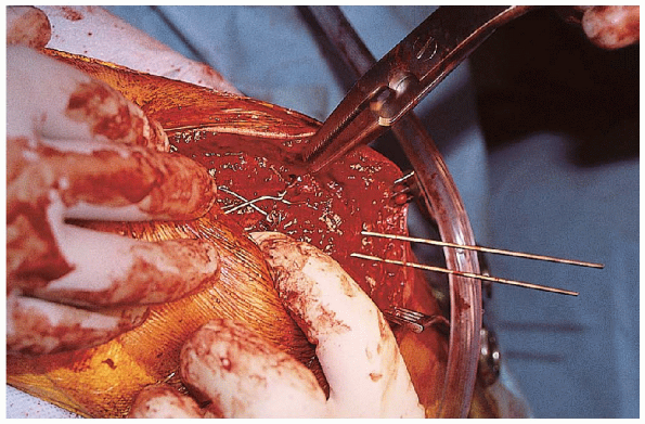
The tourniquet is released. Final radiographs are obtained (Fig. 11-21).
One should confirm that the tension band wire passes anterior to both
K-wires. The fracture is examined through a full range of elbow motion
to verify stability and ascertain that the far end of the K-wires that
engage the far cortex do not restrict forearm rotation (Fig. 11-22).![image]()
The wound is irrigated and closed in layers. A drain is not used if
adequate hemostasis is obtained after tourniquet release. The arm is
placed into a posterior plaster splint.
One should confirm that the tension band wire passes anterior to both
K-wires. The fracture is examined through a full range of elbow motion
to verify stability and ascertain that the far end of the K-wires that
engage the far cortex do not restrict forearm rotation (Fig. 11-22).
The wound is irrigated and closed in layers. A drain is not used if
adequate hemostasis is obtained after tourniquet release. The arm is
placed into a posterior plaster splint.
POSTOPERATIVE PROTOCOL
Initially, the limb is splinted at 90 degrees for 3 to 5
days to promote soft tissue healing. Fractures fixed with the tension
band principle begin early active motion once the incision is clean and
dry. Active and active-assisted motion exercises continue until there
is radiographic evidence of progression to union, clinical evidence of
union (no pain with physiologic stress), and an active range of motion
of at least 75% of the contralateral elbow (75% of normal with
bilateral injuries). The patient begins a progressive-resistance
program designed to strengthen the entire upper extremity.
Functional-capacity evaluations are used for return to work for manual
laborers.
P.123
 |
|
FIGURE 11-21. A and B. Final radiographs.
|
 |
|
FIGURE 11-22.
Placement of the extremity through a range of motion to verify stability and ascertain that the far end of the K-wires that engage the far cortex do not restrict forearm rotation. |
P.124
SUGGESTED READINGS
Cabanela M. Olecranon fractures. In: Morrey BF, ed. The elbow and its disorders. Philadelphia: WB Saunders, 1987.
Colton CL. Fractures of the olecranon in adults: classification and management. Injury 1973-1974; 5: 121-129.
Gartsman GM, Sculco TP, Otis JC. Operative treatment of olecranon fractures—excision or open reduction with internal fixation? J Bone Joint Surg Am 1981; 63A: 718-721.
Hume MC, Wiss DA. Olecranon fractures: a clinical and radiographic comparison of tension band wiring and plate fixation. Clin Orthop 1992; 285: 229-235.
Macko D, Szabo RM. Complications of tension-band wiring of olecranon fractures. J Bone Joint Surg Am 1985; 67A: 1396-1401.
Morrey BF. Current concepts in the treatment of fractures of the radial head, the olecranon, and the coronoid. Instr Course Lect 1995; 44:175-185.
Murphy DF, Greene WB, Dameron TB. Displaced olecranon fractures in adults. Clin Orthop 1987; 224: 215-223.
Rowland SA, Burkhart SS. Tension band wiring of olecranon fractures: a modification of the AO technique. Clin Orthop 1993; 277: 238-242.
Schatzker J. Olecranon fractures. In: Schatzker J, Tile M, eds. The rational basis of operative fracture care. New York: Springer-Verlag, 1987.
Wolfgang G, Burke F, Bush D, et al. Surgical treatment of displaced olecranon fractures by tension band wiring technique. Clin Orthop 1987; 224: 192-204.