
II – FRACTURES, DISLOCATIONS, NONUNIONS, AND MALUNIONS > General
> CHAPTER 10 – FRACTURE HEALING AND CLOSED TREATMENT OF FRACTURES
AND DISLOCATIONS
The section on fracture healing was a separate chapter in the second
edition and was written by Michael Madison and R. Bruce Martin.
Substantial portions of their original chapter are retained in this
revision.
skeletons of wild animals and in archaeologic human skeletons. This
kind of fracture is typically a closed, low-energy fracture with only
slight displacement. Pain probably forced the injured person to protect
his extremity until the fracture healed, and subsequent bone remodeling
smoothed out any rough step-offs at the fracture site. The role of the
surgeon in treating simple fractures of this type may indeed be as
Voltaire characterized it: “to amuse the patient while nature heals the
injury.”
fracture has become increasingly common. This is the high-energy
industrial, vehicular, or ballistic fracture that overwhelms the body’s
capacity to repair it. It demands clinical intervention, the goal of
which is to convert the fracture to a facsimile of a low-energy
fracture that the body is biologically equipped to repair. If the
reduction, fixation, and soft-tissue management of a high-energy
fracture are successful, the fracture can heal by the same cascade of
events that typifies healing of a low-energy fracture.
propagation in certain predetermined directions. The lamellar junctions
and cement lines of bone are weak, and they crack more easily than the
bulk of the material. These weak interfaces are oriented so that the
cracks travel along
and
around the bone, rather than directly across it. Energy that would
quickly break a bone is used in forming longitudinal or circumferential
cracks that do not cause failure and that can be repaired by remodeling
(50).
of loading. It is strongest in compression, weakest in shear, and
intermediate in tensile failure stresses. When a bone is fractured by
compression, it tends to fail along planes that carry the highest shear
stresses, which reach the failure level first; these planes typically
are at an angle of 45° to the load direction. When a bone is bent, the
highest stresses are tensile and compressive; failure begins on the
tensile side and propagates toward the compressed side. When the crack
enters the compressed tissue, it again tends to travel along the 45°
planes of maximum shear, causing splitting, butterfly chips, or other
types of comminution.
longitudinal shear because the transverse shear stress created by the
twisting is across rather than along the fibers. The tensile stresses,
however, lie at a 45° angle to the fibers and have only to separate
them rather than to break through them to cause failure. Torsion
typically produces a break that spirals around the bone at this angle
and returns to its starting point along a longitudinal shear stress
plane.
break into many pieces. The energy is propagated through the bone as a
stress wave (similar to a sound wave or an earthquake), and the greater
its magnitude, the more likely it is that many parts of the bone will
reach a failure criterion virtually simultaneously. The velocity of a
stress wave in bone is about 3,000 m/sec. The energy required to break
a bone is small compared with that encountered in daily activities.
to break the shaft of an adult tibia or femur. The energy released when
a 70 kg person falls to the ground from a standing position is about
500 J. The ability to absorb this energy using eccentric muscle
contractions and deformations of soft tissues usually prevents
fractures from occurring in insignificant falls. If this ability is
impaired by surprise, restrictions, or incapacity, fracture occurs
easily. The propensity of elderly people to fracture their bones easily
reflects the weakness of their bones and the weakness of the muscles
and ligaments that fail to adequately absorb the applied energy, which
instead is transmitted to the bones.
accident in two ways. First, loads applied perpendicular to the tissues
compress them and propagate stress waves up and down the body. The
tissues effective in this way are skin, fat, and muscle (and fur on
animals or clothing on humans). Second, tissues such as fascia,
tendons, ligaments, joint capsules, and contracted muscle brace bones
against bending by supporting part of the tensile stresses. They absorb
energy as they are stretched, but they must be nearly as stiff as the
bone to be effective. One implication of these mechanisms of energy
dissipation is that in very high energy (high-power) fractures, damage
to the soft tissues tends to parallel the degree of damage to the bone;
thus, the most severe fractures tend also to have severe impairment of
the associated soft tissues on which fracture healing depends.
healing may be considered to consist of three overlapping phases: an
inflammatory phase, a reparative phase, and a remodeling phase (21).
This scheme, based largely on descriptive histology, has been widely
reiterated. Others have divided fracture healing into four or five
phases (30,53,99).
These divisions are somewhat arbitrary and reflect differences in
emphasis more than in content. Common to all is the concept that the
fracture initiates a biologic cascade, a sequence of steps activated by
and depending on the previous steps. For convenience, we describe
fracture healing in terms of the three phases recognized by Cruess and
Dumont, noting that the reparative phase combines several processes.
causes the patient to protect the injured part, and swelling
hydrostatically splints the fracture. At the tissue level, the
inflammatory phase is identical to the typical inflammatory response of
most tissues to traumatic injury. Vasodilation and hyperemia,
presumably mediated by histamines, prostaglandins, and various
cytokines, accompany invasion of the injury site by neutrophils,
basophils, and phagocytes that participate in clearing away necrotic
debris. The fracture hematoma becomes organized as a developing fibrin
network that provides pathways for cell migration. It is also presumed
that during the inflammatory phase, various noncollagenous protein
growth factors that regulate cell migration and differentiation and
that normally are trapped in the bone matrix are released into
solution, where they become active (25,59). The inflammatory phase peaks within 48 hours and is quite diminished by 1 week after fracture.
few days after fracture and persists for several months. Its chief
feature is the development of a reparative callus tissue in and about
the fracture site that gradually is transformed to bone. The callus may
consist of cartilage, fibrous tissue, osteoid, woven bone, and vessels.
bone to local inflammation, whether the inflammation is caused by
fracture, infection, a foreign body, or a neoplastic process (44,53). Two salient features of the primary
callus response deserve mention. The first is that the response appears
to be relatively independent of mechanical factors, as evidenced from
the significant primary callus response to a foreign body or at the end
of an amputation stump (i.e., half-fracture), or the cap of callus that
may appear at the protruding end of a hollow intramedullary rod (44,53).
Second, the primary callus response does not continue indefinitely. If
the primary callus (i.e., the provisional callus) has failed to unite
two sides of a fracture within a few weeks, it may cease to grow and be
resorbed, as may be observed of the callus at the amputation stump or
on one side of a large segmental defect.
fracture ends, healing progresses to the stage of bridging callus or
hard callus. Although bridging callus seems to imply the directed
growth of tissue outward from the viable regions distal and proximal to
the fracture, the hard callus seems to differentiate simultaneously
throughout its distribution, rather than growing as an advancing front.
Calcification of the callus may be by direct bone formation by
osteoblasts or by endochondral ossification, depending on the local
oxygen tension (4). Typically, growth of a
large callus greatly outpaces the ingrowing vessels, and endochondral
ossification predominates. In a small, mechanically stable defect, such
as a drill hole, primary (intramembranous) woven bone formation
predominates.
from the marrow and the periosteum. The number of osteoblasts and
osteocytes present at the time of fracture is insufficient to sustain
the high anabolic demands of the growing callus (30).
The differentiation of pluripotential mesenchymal cells, fibroblasts,
and chondroblasts is the primary source of callus cells. (Induction
refers to the differentiation of mesenchymal cells into chondroblasts
or osteoblasts in tissues that do not normally form bone, as observed
in various animal experiments. Induction in this sense is not directly
applicable to fracture healing.)
becomes internally immobilized, and the examiner may consider the
fracture to be healed. The initial calcification is remodeled by
osteoclasts and osteoblasts, leading to the replacement of calcified
cartilage and woven bone by lamellar bone in the final (remodeling)
phase of fracture healing. This phase represents the normal remodeling
activity of bone, although it may remain accelerated in the region of
the fracture for several years, replacing each volume several times
over. In children, the remodeling phase proceeds more vigorously and
includes modeling (independent resorption and formation) and remodeling
(formation coupled to resorption). The result of the remodeling phase
is a gradual modification of the fracture region under the influence of
mechanical loads until it reaches some threshold of optimal shape,
which typically is similar to the shape it had before fracture.
fragments and rigid fixation, as may be achieved for instance by
compression plating an osteotomy, the callus response may be suppressed
altogether. In this case, healing proceeds by normal osteonal bone
remodeling. As an increasing number of osteons cross the fracture site,
the two sides become united. Although primary bone healing has been
considered by some to be a goal of fracture repair, it offers no
particular advantage over normal, callus-mediated (i.e., secondary)
bone repair (75,86). It
proceeds very slowly, especially in adults, and the intermediate stages
are weak. A second potential disadvantage of primary bone healing is
that, unlike callus-mediated healing, it does not progress in an
anaerobic environment.
The medullary system, which chiefly supplies the diaphysis, derives
from the nutrient artery. The metaphyseal system supplies chiefly the
cancellous bone of the proximal and distal metaphyses and anastomoses
with the medullary system. In a child with open physes, the epiphysis
and metaphysis have separate blood supplies. After closure of the
physes, these two anastomose and are thereafter referred to as the
metaphyseal system.
periosteum, especially at regions of fascial or tendinous attachments.
These vessels penetrate and supply the outer third or less of the
cortex. Wherever the surface of the bone is covered by articular
cartilage, a periosteal blood supply is absent. Regions of bone in
which a large proportion of the surface is articular, such as the
talus, carpal scaphoid, and femoral head, are therefore at particular
risk for ischemic damage after trauma because they lack a major source
of vascularity (31,32).
medullary vein, which drains much of the medullary and endosteal
cortical portion of the bone before exiting through the same foramen by
which the nutrient artery enters, and a system of periosteal veins.
Anastomosis between the afferent and efferent arms of the vascular
system is through marrow sinusoids in the medullary region or through
small arterioles within the haversian systems. There is no capillary
bed per se. Rhinelander observed that the principal direction of blood
flow is centrifugal, from the endosteum to the periosteum (76).
Parallel to this is a centrifugal bulk flow of interstitial fluid along
a pressure gradient from approximately 20 mm Hg in the medullary canal
to near zero peripherally (67,87).
depends on the nature and severity of the fracture. In a minimally
displaced fracture, the small vessels in cortical bone are disrupted,
resulting in ischemic death of the osteocytes near the fracture line,
but the major medullary and periosteal vessels may be sufficiently
elastic to remain intact. The medullary system may be the primary
source of the vascular hyperplasia that supplies the callus.
the medullary vascular system, the metaphyseal or periosteal vessels
may play a greater role in vascularization of the callus. Rhinelander
considered that a fourth afferent vascular system, arising from
adjacent soft tissues (especially muscle), could serve as the primary
source of new vascular growth after a displaced fracture in which the
medullary and periosteal systems were grossly disrupted (77,78).
Support for this concept comes from the observation that fracture
healing is enhanced by the use of muscle flaps. A study of segmental
tibial fractures in dogs demonstrated significantly increased blood
flow 30 days after injury for the fractures covered with muscle flaps
compared with those covered by skin alone (79).
fracture. In experimental fractures of canine tibias, the regional
blood flow near the fracture reached its maximum (six times normal) by
10 days after injury and was still elevated 4 months later. Blood flow
in the same tibia but distant from the fracture site was also elevated,
reaching its peak 1–3 weeks after injury and declining gradually
thereafter (68). Gupta et al. showed that blood vessels crossed the fracture line after about 3 weeks in fractured dog tibias (36).
In humans, failure of transfracture vessels to form by 10 weeks, as
indicated by osseous phlebography, is considered a sign of impending
nonunion (74).
periosteal ischemia directly beneath the plate, but the procedure
otherwise does not interfere with regional revascularization (73).
Placement of a reamed intramedullary nail obliterates the medullary
blood supply, however, shifting the source of vessel ingrowth to the
metaphyseal, periosteal, and soft-tissue systems (77).
In a canine study, fixation with an intramedullary nail led to reduced
blood flow at 14 and 90 days and reduced callus formation compared with
fixation with a plate, although all fractures united regardless of
fixation method (3). A nonreamed nail or a
tight-fitting nail that is fluted leaves channels in the medullary
cavity that soon are invaded by medullary arteries.
pharmacologically by vasoconstrictors, vasodilators, and their
antagonists. Brinker et al. propose that use of these agents to promote
local blood flow in bone may prove useful therapeutically in managing
delayed unions or infected fractures (13).
vigorously in children than in adults. In elderly people, fracture
healing may proceed very slowly, and what is normal healing in a
75-year-old patient would be a delayed union in a young person. Slow
healing does not seem to be an inherent cellular problem of aging,
because osteoblasts from trabecular bone grown in culture show similar
metabolic characteristics regardless of the age of the donor (24).
fracture patients exhibit strong seasonal variation, with higher levels
in summer, when solar radiation is greatest. It has been suggested that
impaired dietary intake of vitamin D in the elderly shifts the balance
toward endogenous vitamin D, which depends on solar ultraviolet
radiation as a catalyst (56,57).
This finding has been shown to correlate with the seasonal incidence of
hip fractures, although an unequivocal relationship to fracture healing
has not been demonstrated.
neoteny has played a significant role in their evolution, rodents may
be considered better models of fracture healing in human children than
in human adults. Much experimental work on fracture healing and on bone
induction that has been done on rodents cannot be assumed to apply
directly to adult humans (12).
the red (hemopoietic) marrow in the appendicular skeleton is replaced
by yellow (fatty) marrow, beginning with the toes and fingers and
proceeding proximally. In the adult, the red marrow is confined chiefly
to the axial skeleton, with a small amount of red marrow remaining in
the proximal femur. Red marrow is highly osteogenic, and bones with red
marrow (e.g., ilium, vertebral bodies, ribs) generally heal readily
compared with regions of yellow marrow (e.g., tibial diaphysis).
The axial bones are also those that retain red marrow, a fact that may
in part explain their more vigorous healing. Temperature, however, may
also be a factor in fracture healing: It has been shown that fractures
of vertebral bodies in mice heal much more rapidly when kept at higher
temperatures (63).
diminishes the size of a fracture callus. It also causes a deficit in
the bone laid down during remodeling of the callus. Growth hormone, on
the other hand, has the capacity to increase callus volume, but it is
effective therapeutically only in the absence of normal endogenous
growth hormone. Experimentally, growth hormone has accelerated healing
in old rats (2). Parathyroid hormone and
thyroxine increase the rate of bone remodeling; abnormally low values
of these hormones reduce the rate of remodeling in the final phase of
fracture repair. Serum calcitonin and 24,25-(OH)2-D3
are significantly elevated during the first 6 weeks of fracture
healing, but their effects on fracture healing are not entirely clear (57).
medullary canal) appears to liberate a systemic circulating factor that
stimulates bone growth or mineral apposition elsewhere in the skeleton.
This phenomenon has been shown experimentally in rodents and in
patients undergoing marrow aspiration (23,26).
It has long been known that patients with severe head injuries heal
fractures very aggressively and have a high propensity to make
heterotopic bone. Serum from these patients stimulates osteoblasts in
tissue culture, compared with serum from patients with other fractures (8).
These observations suggest that one or more circulating systemic agents
may regulate fracture healing, but these agents have not been
identified.
normally, but the resulting bone tissue has a mineral deficit.
Similarly, fractures in osteoporotic patients heal normally, but the
remodeled fracture site is osteoporotic.
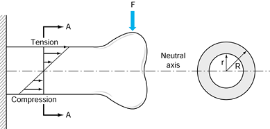
depends on the product of a geometric factor and the strength or
stiffness of the material within. If the geometric factor is made
larger, the structure can be made of a weaker material and be just as
strong (Fig. 10.1). A callus composed of
material that is relatively weak, for example, can nonetheless achieve
the strength of the intact bone if its diameter is greater.
 |
|
Figure 10.1. For a bone loaded in bending by a force F,
at any cross section there is tensile stress on the upper surface and compression on the lower surface. Consequently, there is a line through the middle of the section where the stress is zero; this is called the neutral axis. The contribution of each moiety of bone in the cross section is the product of its area and the square of its distance from the neutral axis. For a tube, the cross-sectional moment of inertia (CSMI) is π/4(R4 – r4). The section modulus equals the CSMI divided by R. |
fracture healing: The strength and stiffness required for functional
union are achieved rapidly by formation of a callus that has poor
material but has a high section modulus (large diameter). Woven bone
and calcified cartilage, although weaker than lamellar bone, can be
produced two to five times faster. By locating much of this material
farther from the center of the bone than the original cortex, nature
compensates for the mechanical inferiority of the callus materials.
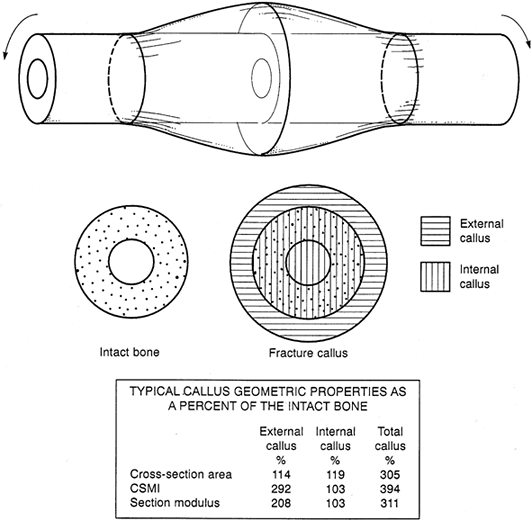
principle, using dimensions typical of a large bone fracture callus.
The external callus itself may easily achieve twice the section modulus
of the intact cortex, and the total callus may have triple this value.
The callus material needs to be only one third to one half as strong as
cortical bone for the callus to return the bone to normal strength. By
the same token, the strength of an abundant, mineralized callus can
substantially exceed that of the original and adjacent cortex.
 |
|
Figure 10.2.
A typical long-bone fracture callus. The external callus is defined as that located outside the original bone cortex; the remainder of the callus is the inner callus. Assuming that the diameters of the endosteal, periosteal, and callus periphery are 10, 25, and 35 mm, respectively, the geometric properties of the callus are shown as percentages of the intact bone in the table. Note that the section modulus of external callus alone substantially exceeds that of the intact bone, although its area is only slightly greater. |
environment is one of the principles of fracture management. We now
recognize that absolute rigidity should not be the goal of mechanical
intervention, because it entails two potential disadvantages: Stress
protection by fixation devices may cause bone resorption, and lack of
motion at the fracture site inhibits callus formation (72).
Fracture healing seems to benefit from a certain amount of controlled
axial loading and micromotion, although how much is “just right” is
unknown (34,45,54).
Ribs heal with quite a bit of motion; a tibia probably tolerates much
less. The use of less rigid materials (e.g., titanium rather than
stainless steel) and the intramedullary rather than cortical placement
of fixation devices (which decreases the sectional modulus) tend to
increase the amount of micromotion at the fracture site (101).
In a study of fractured dog femurs, Uhthoff et al. found that cortical
bone loss due to stress protection beneath titanium plates was about
one third that under stainless-steel plates, which were 50% stiffer
than the titanium plates (97). Terjesen and Apalset found that 70% to 95% reductions in plate stiffness resulted in a 16% to 100% increase in callus size (92).
increasingly by the bone and less by fixation devices. This gradual
shift can be achieved by using unlocked intramedullary devices or by
dynamizing locked nails or external fixators. Resorbable implants that
are now on the market also have great potential for effecting a gradual
transition of load bearing from the device to bone, provided that their
resorption kinetics can be adequately regulated. Plates and screws are
much less amenable to a gradual shift of load bearing to the bone.
Streaming potentials are produced when interstitial fluids are forced
through the calcified matrix by dilatation of some regions and
compression of others. Piezoelectric potentials are produced by
deformation of the collagen molecules. Both electrical potentials are
transient when produced by physiologic loads, because streaming occurs
only while deformation is in progress, and piezoelectric potentials
produced by a prolonged load are canceled by migration of opposite
charges in the interstitial fluids. A permanent electrical polarization
is associated with collagen in bones, however, and this permanent
polarization appears to be altered when fracture occurs (2). The fracture site becomes negatively charged (7). It has been postulated that this polarization is related to the cascade of biological events that result in repair.
to an electrical field (7,9).
Because osteoblast stem cells may include circulating mesenchymal
cells, investigators thought that stress-generated potentials might be
responsible for the differentiation of osteoblasts and play a role in
fracture healing and Wolff’s law (i.e., a bone develops the structure
most suited to resist the forces acting on it). Laboratory
investigations show that bone formation is promoted in the neighborhood
of a cathode, that fresh fractures in animals gain strength more
quickly when electrically stimulated, that disuse osteopenia is
inhibited by electrical treatment, and that bone and cartilage cells in
culture exhibit increased DNA synthesis and other changes when
electrically stimulated (28,29,38,43,47,52,65,66,82).
These findings suggest that the functions of skeletal cells may be
selectively altered by electrical signals arising from normal loading,
fracture, or clinical intervention. This hypothesis has been tested in
numerous clinical trials involving various types of fracture nonunions.
for introducing alternating electrical currents in the bone. Brighton
et al. implanted a cathode directly into the fracture site and passed
about 20 µA of electricity to a supercutaneous anode (12).
Bassett et al. passed electricity through a pair of wire coils disposed
on either side of the fractured limb to induce an alternating magnetic
field in the region of the fractured bone (5).
Magnetic fields penetrate tissues much more readily than electrical
fields, and the amount of current required is low enough to allow
battery power. The alternating magnetic field induces similarly varying
electrical fields and currents in the tissues at the fracture site.
generally claimed that treatment of fracture nonunions has been
substantially more dependable than more conventional methods (i.e.,
grafting). These claims have been disputed by critics who assert that
the studies have not been adequately controlled. For various reasons,
it has been difficult to do well-controlled human studies, but the
laboratory work strongly supports the theory that electrical currents
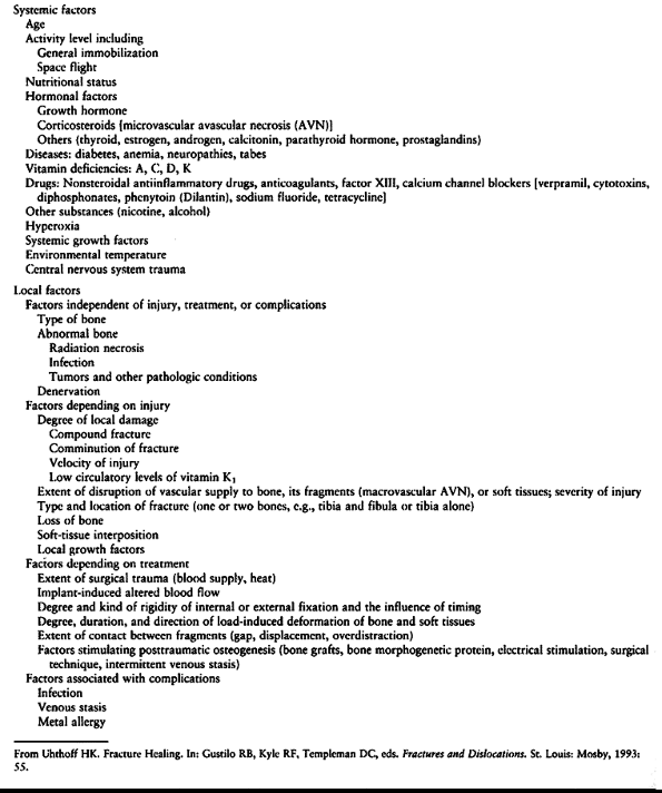
or fields modulate cell function in the skeleton. See Table 10.1 for a summary of factors influencing fracture healing.
 |
|
Table 10.1. Factors Influencing Fracture Healing
|
progress for several years. Although the criterion is somewhat
arbitrary, a fracture is usually considered healed when the bone can
tolerate the loads normally experienced in everyday activities.
Traditionally, healing has been determined by evidence of bridging
callus on radiographs and by stiffness across the fracture site during
clinical manipulation. These traditional measures of healing are
sufficient for the purposes of fracture management; for some
experimental studies or for careful evaluation of devices or
techniques, however, a more precise determination of the progress of
fracture healing is useful. Three general methods are currently
available.
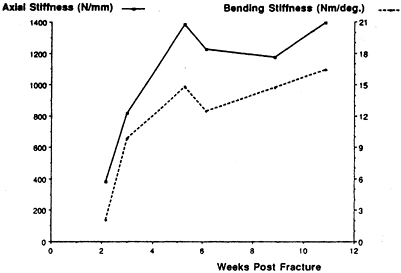
response to a known load can be measured; this is a refinement of the
clinician’s subjective feel of stiffness when she manipulates the
fracture. Typically, a strain gauge attached to an external fixator is
used to measure the deflection of a tibia in response to known applied
loads (17,22). An example of fracture healing measured in this way is shown in Figure 10.3.
 |
|
Figure 10.3. Increase in axial stiffness (solid line) and bending stiffness (dashed line)
of a healing distal-third spiral tibia fracture as measured from an instrumented external fixator. Threshold values of fracture stiffness for safely removing the fixator are 1,000 newtons per millimeter (N/mm) in axial loading (in this patient, reached at 4 weeks) and 15 newton-meters (Nm) per degree in bending (in this patient, reached at 10 weeks). (From Cunningham JL, Kenwright J, Kershaw CJ. Biomechanical Measurement of Fracture Healing. J Med Eng Technol 1990;14:92.) |
cause the fractured bone to vibrate by tapping it with a hammer or
vibrating it with a shaker, and then measuring the resonant frequency
of the bone as a whole or the attenuation of the impulse as it crosses
the fracture site (19,71). Healing is assessed by comparison to the intact, contralateral bone.
on measuring the velocity of an ultrasonic wave (from an ultrasound
unit) across the fracture site (33). As the
fracture heals, wave velocity increases. As with the vibrational tests,
healing is measured by comparison with the contralateral uninjured bone.
years has focused on perfecting the management of the mechanical
environment, it seems likely that future progress will emphasize the
biologic side of fracture healing. Currently, two avenues of biologic
intervention are being developed. Stimulation of osteogenesis involves
enhancement of the migration, division, differentiation, or metabolism
of cells that normally carry out fracture repair. A clinical example is
delayed primary fixation, in which surgical intervention a week or so
after the fracture may reactivate or amplify the cascade of fracture
healing (30,100).
Electrical stimulation also is presumed to enhance osteogenesis, as is
the therapeutic use of protein growth factors. Support of
osteoconduction involves the provision of a substrate or scaffold along
which osteogenic cells can migrate and on which angiogenesis and
osteogenesis can occur. Provision of osteoconductive material is
particularly important in repair of a segmental defect. Collagen is the
natural osteoconductive material, although other proteins and ceramics
are being used experimentally and clinically as osteoconductors. The
combination of an osteoconductive material with a stimulant of
osteogenesis promises to provide a very effective synthetic bone graft.
agents are still fairly primitive, this area holds great promise for
further improvements in the regulation of fracture healing. Clinical
application of biologic agents would fulfill a prophetic remark made by
Dr. Girdlestone 70 years ago, when he foresaw the future of
orthopaedics shifting from “carpentry to gardening.”
been a remarkable change in the treatment of fractures and
dislocations. When I began my orthopaedic surgery resident training in
1963, the standard of care for fractures of the shaft of the femur was
skeletal traction, which required an average of 3 months of
hospitalization. The standard today is closed, locked intramedullary
nailing with an average hospital stay of 4–7 days.
advances in anesthesia, improvements in sterile technique, and advances
in the technology of internal fixation. We can now operate on patients
who were previously not candidates for surgery, perform surgery with a
minimal risk of infection, and internally fix on a reliable basis
fractures that were previously not fixable. Operative treatment now
dominates the treatment of musculoskeletal trauma to such an extent
that residents today have far less training in the principles of closed
management.
treatment is driven by our outcome-oriented society. Patients expect
not only that fractures will heal, but that they will heal in anatomic
position with restoration of normal function. Often these expectations
are unrealistic in view of the severe injuries that occur in our
high-velocity society. Many injuries are now occurring in the context
of the multiply injured patient, where the need for early mobilization
makes nonoperative techniques impractical. For example, in the
Orthopaedic Trauma Service at the University of California, Davis
Medical Center, the average number of fractures per patient is 3.5.
Surgical techniques offer the ability to restore anatomy close to
normal. The rigid fixation obtained often allows early mobilization and
rehabilitation, which optimizes the outcome.
nonoperative care remains the foundation on which treatment of
musculoskeletal trauma is based. There are many indications for
nonoperative care, and modern orthopaedic surgeons must be as skilled
in nonoperative as they are in operative techniques. A sound knowledge
of nonoperative techniques also makes the use of operative techniques
more effective and safer. Closed treatment requires as much
thoughtfulness, technical expertise, and attention to detail as does
surgery.
orthopaedics, I feel it is essential to provide information on
nonoperative care, and this information is scattered throughout the
chapters in these volumes. This section of this chapter on closed
treatment of fractures and dislocations lays the groundwork for the
other chapters in this section of the text on treatment of fractures.
Although modern textbooks on fracture care, such as those by Rockwood (80,81) and Browner (14)
and their colleagues, cover these techniques in detail, the interested
reader will find it very enjoyable and educational to go back to two
classic works on fracture care, Watson-Jones’s Fractures and Joint Injuries (98) and Charnley’s The Closed Treatment of Common Fractures (18). A monograph by Bleck et al. (10) on plaster cast techniques and a manual by Freuler et al. (27) provide good detail on nonoperative management techniques using plaster and splints.
presence of motion, although deformity is common. Union occurs because
the vascular supply to the bone and surrounding soft tissues is usually
good, and the physiologic stimulus of continued use of the limb
enhances callus formation
and
strengthens the callus formed. In the initial healing process, an
ensheathing callus is formed that begins to immobilize the fracture
fragments. Early during fracture healing, motion can still occur at the
fracture, but translation of the fracture fragments and shortening is
usually impossible after the initial ensheathing callus has formed.
Most bone in fracture callus comes from endosteal tissues, which
quickly fills in the ensheathing callus. As it becomes progressively
thicker, total immobilization of the fractured bone ends occurs. This
method of healing has the mechanical advantage of producing a callus
that is much larger in diameter than the fractured bone. It takes
advantage of the increased polar moment of inertia created by the thick
callus. After complete consolidation, in fact, this thickened area of
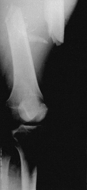
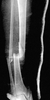
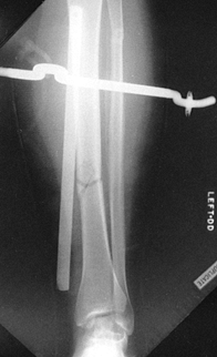
bone is often stronger than the unaffected shaft (Fig. 10.5).
The bone ends themselves are usually somewhat avascular because of the
injury and do not directly participate in this early phase of healing.
 |
|
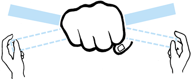
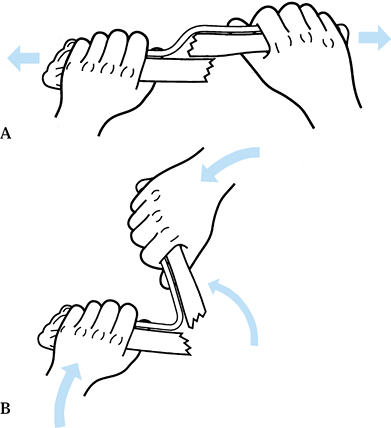
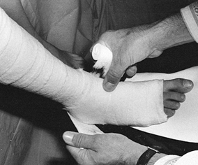
Figure 10.4.
An analogy between early fracture callus and a fist gripping a stick. The ensheathing callus represented by the fist is stationary and markedly reduces the motion of the stick, but the stick and the bones of the fracture can still move inside the clenched fist. (From Charnley J. The Closed Treatment of Common Fractures, 3rd ed. Baltimore: Williams & Wilkins, 1963.) |
 |
|
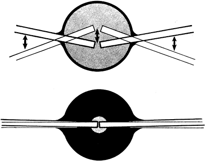
Figure 10.5.
As the circumferential callus fills with bone, the ensheathing callus becomes thicker, shrinks on the enclosed fragment, and eventually eliminates motion in the bone fragments. The increased moment of inertia relative to the adjacent normal bone makes the healed site stronger than the adjacent bone for a period of time. (From Charnley J. The Closed Treatment of Common Fractures, 3rd ed. Baltimore: Williams & Wilkins, 1963.) |
ends are slowly revascularized and remodeled. The large peripheral
callus is slowly resorbed and the shape of the bone returns toward
normal after several years of remodeling. This type of union is
virtually 100% successful in nature in ribs, clavicles, and membranous
bones. In the mid diaphysis of such bones as the tibia, the limitations
of blood supply and excessive motion produced by attempted use of the
limb commonly lead to nonunion.
to hold the broken bone in a position as close to its anatomic position
as possible to prevent malunion, to reduce excessive motion in order to
prevent nonunion, and to allow earlier function than would otherwise be
possible. In addition, the immobilization substantially reduces pain.
dissection and direct mechanical trauma to bone, reduces the blood
supply to bone and the surrounding soft tissues. Except for closed
intramedullary nailing, bone union usually takes longer if operative
methods are used. Because of the prolonged period necessary for
revascularization, rigid fixation over long periods of time is usually
required. With rigid fixation, bone union occurs by direct osteonal
modeling and callus formation is suppressed; this results in slower and
mechanically less strong union. The combined risks of
devascularization, slower and weaker bone union, and operative
complications must be offset by the advantages to be gained by
operative treatment.
except for displaced intraarticular fractures; some avulsion fractures
with wide displacement, such as those of the medial epicondyle of the
elbow; and shaft fractures of the femur in older children who have
severe, life-threatening multiple injuries. Certain fractures that are
difficult to
manage
by closed technique, such as supracondylar fractures of the humerus,
are now routinely treated with percutaneous pin fixation.
they grow, and during the active growing years long-bone fractures of
the lower extremity are commonly accompanied by some overgrowth.
Nonunion is rarely a problem in children. Despite prolonged
immobilization, in contrast to adults, the vast majority of children
very quickly regain normal joint motion and muscle strength. For those
reasons, children’s fractures are nearly always treated with closed
techniques. See Chapter 164 on the operative treatment of children’s fractures.
surgery. Internal fixation is rarely indicated, as the fracture is in
anatomic position and will heal rapidly. Notable exceptions include
undisplaced fractures of the femoral neck, which usually require
percutaneous pin or screw fixation to prevent displacement.
common problem. Osteoporotic bone is very difficult to fix internally,
and therefore nonsurgical methods are commonly indicated in the very
elderly. Nonoperative treatment methods, however, can severely impede
the mobility of the elderly. Methods such as cast-bracing are often
used to avoid prolonged bed rest. Compromises are usually necessary so
that early rehabilitation is possible. For example, Colles’ fractures
in the very elderly are almost always treated in short-arm casts rather
than long-arm casts.
common problem following high-energy trauma. Many intraarticular
fractures, such as those of the tibial plateau and ankle, may not be
fixable because of severe comminution. These cases require either
external fixation or nonoperative methods.
intervention; and certain systemic diseases, such as an
immunodeficiency, may make the hazards of surgery sufficiently high
that nonoperative methods are required.
soft-tissue conditions may contraindicate surgery and make nonoperative
methods necessary.
excellent cooperation on the part of the patient to ensure an optimal
result. Patients with psychiatric or personality disorders, or who
otherwise cannot participate in postoperative care, may need to be
treated by nonoperative means.
forces. Direct injuries may break the bone directly under the blow,
usually by imparting a bending force. Indirect injuries occur when the
limb is twisted or angulated distally, causing a more proximal injury;
an example is the spiral fracture of the tibia that occurs in the
typical external-rotation, twisting injury associated with skiing
accidents. When these injuries occur, the soft tissues tend to be
disrupted on one side of the fracture and left intact as a hinge on the
other. For example, in fractures of the tibia caused by bending forces,
the periosteum and muscle envelope on the convex side of the fracture
is often disrupted, but the soft-tissue envelope on the concave side
remains intact (Fig. 10.6 and Fig. 10.7).
 |
|
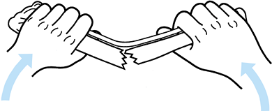
Figure 10.6.
Soft-tissue hinge. When the fracture breaks because of bending, the soft tissues disrupt on the convex side and remain intact on the concave side. (Redrawn from Charnley J. The Closed Treatment of Common Fractures, 3rd ed. Baltimore: Williams & Wilkins, 1963.) |
 |
|
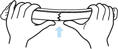
Figure 10.7.
Three-point fixation. When the fracture is reduced and three-point fixation applied, the fracture becomes stable. (Redrawn from Charnley J. The Closed Treatment of Common Fractures, 3rd ed. Baltimore: Williams & Wilkins, 1963.) |
precise mechanism of injury, but it can be inferred by the
configuration of the fracture. For example, in bimalleolar fractures of
the ankle, a transverse fracture of the medial malleolus and a spiral
fracture of the lateral malleolus are compatible with an external
rotation-eversion force causing the fracture. With this knowledge, it
is possible to reduce the fracture by reversing the mechanism of
injury, taking advantage of the soft-tissue hinge to stabilize the
fracture. With appropriate maneuvers, the soft tissues guide the
displaced fragments back to their normal position. This mechanism
applies to many fractures, including
Colles’ fractures and supracondylar fractures of the humerus and femur.
surgeon to take advantage of three-point fixation, which produces
tension in the intact soft tissues and therefore compression across the
fracture site. This compression immobilizes the fracture (Fig. 10.7).
This principle is used in nearly all cast and splint immobilization of
fractures. Applying the three-point fixation principle usually requires
a splint or cast that appears overreduced. A straight cast will usually
contain a crooked bone; a curved cast will generally contain a
well-aligned bone.
advantage, in some cases it can be an impediment to reduction. The best
example is in fractures of the distal radius and ulna in children. The
periosteum is quite thick. With complete dorsal displacement and
overriding, straight longitudinal traction to reduce the fracture is
ineffective because the soft-tissue hinge is too short to allow
reduction of the fracture fragments (Fig. 10.8).
In this case, reduction requires that the fracture be deformed, as in
the mechanism of injury, and overreduced. Three-point fixation can then
take advantage of the soft-tissue hinge to hold the reduction. Because
of the extreme deformity required to reduce fractures of this type, it
is usually advisable to do the reduction under general or regional
anesthesia so that it can be gentle and need be performed only once or
twice.
 |
|
Figure 10.8. A:
Mechanism of fragment interlocking produced by an intact soft-tissue hinge, typically seen in fractures of the distal radius and ulna in children. Traction does not allow the fragments to be disimpacted and brought out to length. B: Reproduction of the mechanism of fracture to hook on the ends of the fracture. Notice that angulation beyond 90° is usually required. (Redrawn from Charnley J. The Closed Treatment of Common Fractures, 3rd ed. Baltimore: Williams & Wilkins, 1963.) |
provide an aid to reduction. An analogy is to picture pieces of
macaroni strung on a string. When the string is loose, the pieces are
haphazardly arranged; with tension on the string, they line up. The
same principle applies to comminuted fractures of the shaft of the
femur. Axial skeletal traction, by putting tension on the soft-tissue
envelope around the femur, lines up the bone segments.
fractures can be the hydraulic effect of soft-tissue swelling.
Shortening in fractures is generally not caused by muscle spasm, but
rather by the hydraulic effect of soft-tissue swelling. With bleeding
and edema, the soft-tissue envelope around the fracture increases the
pressure inside the deep fascia. Since the geometric shape that
contains the largest volume is a sphere, the limb’s normal oblong,
tubular shape becomes spherelike. The limb shortens, causing the bone
fragments to override (Fig. 10.9). Traction to
correct this overriding may cause compartment syndrome by elongating
the thigh and increasing the intracompartmental pressure.
 |
|
Figure 10.9.
Effect of hydraulics on fracture shortening. The normal shape of the thigh is that of a tube or sausage. With a fracture, hemorrhage into the thigh occurs, which causes it to assume the shape of a sphere, thus inducing shortening in the fracture. |
The initial radiograph often points to the degree of soft-tissue injury
and instability. In fractures of the tibia with unstable patterns,
plaster of Paris cast management alone usually results in shortening
equal to that seen on the original radiograph (Fig. 10.10).
Excessive shortening is a hallmark of more severe soft-tissue injury,
and without special measures to prevent shortening, the fracture will
heal in a shortened position. Transverse fractures with good end-to-end
contact are stable against shortening; the challenge is simply to
control angular and rotational deformity, which can usually be done
with a cast or splint (Fig. 10.11).
 |
|
Figure 10.10.
The amount of shortening seen on the initial postinjury x-rays indicates the degree of soft-tissue stripping that has occurred about the fracture site. |
 |
|
Figure 10.11.
In stable fractures such as this transverse fracture, shortening is rarely a problem, but care must be taken to avoid angulation and malrotation. |
for three-point fixation, then with proper immobilization many
seemingly unstable fractures are potentially stable against shortening.
A typical example is the Colles’ fracture, which is inherently unstable
in shortening. If the fracture is adequately immobilized with a
three-point fixation cast, shortening can usually be prevented (Fig. 10.12).
 |
|
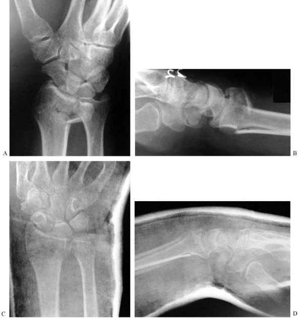
Figure 10.12. A,B:
The inherent instability in shortening of this Colles’ fracture is due to the crush of bone that occurred at the time of injury. C,D: After reduction, the three-point fixation achieved in the cast helps maintain position and length. |
heal within the expected time. This is particularly a problem in the
tibia, where weight-bearing treatment may make control of angulation
difficult. In other fractures, the strong pull of one muscle group or
another induces typical deformities such as late varus in
intertrochanteric or subtrochanteric fractures of the femur, posterior
angulation in supracondylar fractures of the femur, and varus in
fractures in the shaft of the humerus.
joints above and below the fracture can be expected to gain nearly full
anatomic motion and certainly functional motion, if the fracture heals
within the expected time and immobilization is not prolonged. On the
other hand, associated soft-tissue injuries, sepsis, and prolonged
immobilization for treatment of delayed union or nonunion often lead to
loss of joint motion and atrophy of muscle, which are difficult to
reverse. Follow the simple rules in Table 10.1 to minimize problems with limb rehabilitation.
treated with early, protected, gentle active motion. Examples are
surgical neck fractures of the humerus in the elderly, stable fractures
of the radial head and neck, and minimally displaced fractures of the
calcaneus.
they are no longer used because they present the danger of pressure
sores and compartment syndrome. Freuler et al. have shown that the
additional immobilization provided by using unpadded plaster is not
worth the many risks (27).
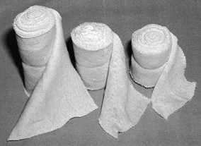
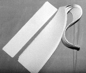
combination is available in widths from 2 to 12 inches and serves as a
useful liner under most casts (Fig. 10.13).
When treating fresh fractures, I prefer not to line the entire cast
with stockinet because, if swelling occurs, the stockinet can be quite
difficult to cut. Place the tubular stockinet only at the ends of the
cast for trimming (Fig. 10.14). When applying stockinet around joints, avoid wrinkles by cutting the stockinet on the concave surface and overlapping it (Fig. 10.15 and Fig. 10.16).
Tubular stockinet can be cut on the bias to produce a bandage material
that is stretchable and conforms well to the extremity but is not
elastic. It is very useful for overwrapping splints and soft dressings (Fig. 10.17).
Heavier specialized knitted stockings are used for cast-braces where
more uniform compression of the limb is desirable, and thicker material
is necessary to protect the limb from the plaster, as the limb will be
used much more actively in a cast-brace.
 |
|
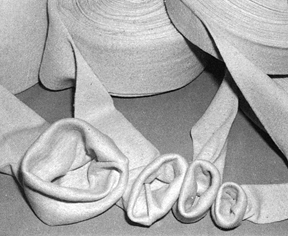
Figure 10.13.
Tubular stockinet is used to line and trim the end of casts, and it has many other uses. It is available in widths from 2 to 12 inches. |
 |
|
Figure 10.14. Tubular stockinet used to trim the ends of a short-leg cast.
|
 |
|
Figure 10.15. To avoid wrinkles in the stockinet under casts, cut along the concave surface of joints.
|
 |
|
Figure 10.16. After cutting the stockinet, overlap it to produce a smooth contour.
|
 |
|
Figure 10.17. Tubular stockinet can be cut on the bias and is very useful for overwrapping splints and dressings.
|
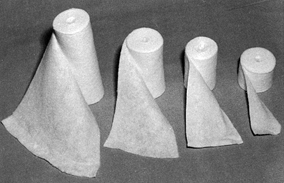
This sheet cotton is fairly noncompressible and, if used thick enough
over bony prominences, can serve as the only padding material in the
cast.
 |
|
Figure 10.18. Sheet cotton for padding casts comes in rolls in widths of 2, 3, 4, and 6 inches.
|
as black felt or a more dense white felt, available up to ½-inch thick.
It can be stripped in half to produce thinner sheets as necessary. Also
useful is synthetic foam padding with adhesive backing, which can be
adhered to the limb over particularly sensitive or prominent areas. The
disadvantage of synthetic foam is that it is more compressible and less
likely to be effective.
used since first developed by the ancient Egyptians. The first plaster
bandages were used by Andonius Mathijsen, a Flemish army surgeon, in
1852. The plaster of Paris used in plaster bandages is derived from
gypsum. Plaster of Paris is made by pulverizing and heating gypsum to
dehydrate it; the result is anhydrous calcium sulfate. When water is
added, it crystallizes back into gypsum in an exothermic reaction. This
exothermic reaction produces enough heat that if a cast is overly thick
and laid on an impervious surface such as a plastic-covered pillow,
second-degree burns can occur. Commercial plaster bandages are made by
coating gauze with the plaster of Paris, using starch as an adhesive.
times and handling characteristics. Most plaster is available in either
a standard or fast-setting variety. Extra-fast-setting plaster, which
sets in 2–4 min, is useful in clubfoot casts on small children.
Standard or fast-setting plaster requires 5–8 min. Setting times are
affected by ambient
temperature,
humidity, thoroughness of wetting, and water temperature. Long crystal
lengths make a stronger cast, and the ideal water temperature is about
22°C (72°F). The plaster should generally be soaked for about 4 min.
Splints are available in 3 × 15, 4 × 15, 5 × 30, and 5 × 45 inches.
Luck describes the parameters affecting plaster strength and use (48).
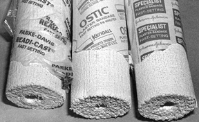 |
|
Figure 10.19.
Commercial plaster of Paris rolls are available in widths of 2, 3, 4, 5, 6, and 8 inches. The type of gauze used and the plaster formulation vary from manufacturer to manufacturer. |
 |
|
Figure 10.20. Plaster splints are available commercially in many sizes. Use them in multiple layers to create adequate strength.
|
available. The weave of the gauze and elastic fibers allows the cast to
be applied more tightly and with more uniform molding over irregular
surfaces. It is useful as the initial layer in cast-braces. It is very
easy to apply elastic cast materials too tightly; use them with caution.
plaster stronger and more water-resistant is also available, but for
the most part it has been replaced by entirely synthetic or fiberglass
cast materials. These materials are lightweight and strong and can be
applied in much thinner constructs than plaster of Paris. They are not
weakened by immersion in water. They are available in many colors and
are very popular with patients. The disadvantages of the synthetic
materials are that they are far more expensive, much more difficult to
apply, and not as versatile as plaster of Paris. In addition, it is
very difficult to mold fractures through synthetic materials, and they
are generally not used in the initial treatment of unstable fractures.
Because of the rigidity of the fiberglass, they cannot be spread. They
can, however, be quite useful as an overwrap of one or two layers on
regular plaster of Paris casts to increase their strength and protect
the outer surface. Allergy is also more common with the synthetic cast
materials; in plaster of Paris, it is nearly unheard of.
tape, muslin bandage, elastic (Ace) bandages, and various dressing
materials. A plentiful supply of good-quality disposable rubber gloves
is essential, as plaster should always be handled with gloved hands to
prevent the rough texture of your skin from dragging the plaster out of
the gauze as it is rubbed, producing a rougher and less desirable cast
finish. Cornstarch and baby powder are useful for dusting
the
skin, particularly where skin contact, such as in the axilla, may
result in irritation. Do not use talcum powder, as it is too rough.
cast wedges are useful for cast wedging and holding split casts open.
Long wood sticks or rolled newspapers are useful for making reinforcing
bars for shoulder and hip spica casts. An indelible pencil for writing
the diagnosis, drawing the fracture, or entering other useful
information on the cast is handy (Fig. 10.21).
 |
|
Figure 10.21.
An indelible pencil is useful for writing on casts. When using an oscillating saw, be sure that the blade is sharp and does not overheat. Use one finger as a fulcrum on the cast to stabilize the blade and cut by pushing downward (arrow) and pulling upward (arrow) when the cast saw is moved along. Avoid bony prominences. Never draw the saw longitudinally, as it can cut skin. |
includes hooks in the ceiling for suspension, broad stainless-steel or
synthetic work surfaces on which to spread plaster, mechanical or
hydraulic tables that can be elevated for plaster application, special
orthopaedic tables for the application of spica casts, bandage
scissors, disposable #10 and #20 blades, an electric cast saw with an
attached vacuum (Fig. 10.21), and special tools for cutting, bending, and splitting casts (Fig. 10.22).
Various types of foam-rubber bolsters and stands or devices for
supporting the limb during plaster application are available and are
quite useful, particularly when the surgeon must work unassisted.
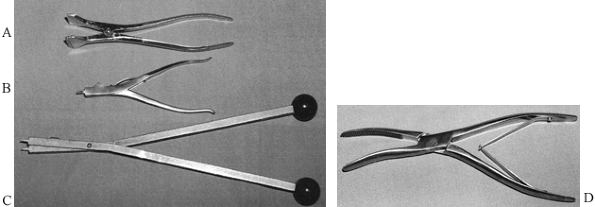 |
|
Figure 10.22. Cast spreaders. A: A two-handed cast spreader. B: Cast spreader designed to be used with one hand; the thin tine is quite useful. C: Another two-handed cast spreader that uses the same tine principle as (B). D: A cast bender for softening the edges of casts.
|
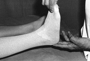
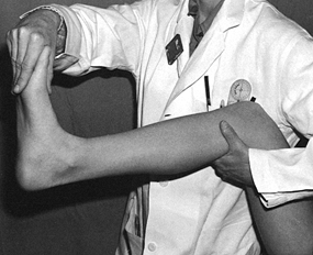
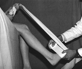
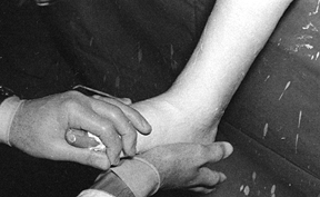
the leg with one hand in the popliteal fossa and support the ankle in a
neutral position with the other hand. If the forefoot is grasped with
the extended fingers and thumb through the first toe web space, it is
easily held without fatigue, and the cast can be applied over the
assistant’s fingers with ease. The additional width produced by the
assistant’s hand also leaves more room for the toes to move once the
cast is completed (Fig. 10.23).
 |
|
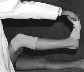
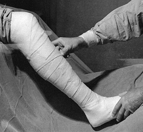
Figure 10.23.
The assistant supports the lower extremity for application of a short-leg cast. The hand grips the toes by extending the fingers over the metatarsal heads. The cast is applied over the assistant’s fingers, which gives room for the toes to move. |
the patient holds a muslin bandage to maintain the foot in a steady
position with the ankle at 90°. In unstable tibial fractures, the thigh
can be supported on a well-padded arm board, using an ankle traction
bandage with a pail attached; water can be poured into the pail to
provide some traction for stabilization of the limb. Placing the
forefoot on the knee (Fig. 10.25) helps
stabilize the limb, holds the ankle at 90°, and allows the surgeon to
control rotation. This technique is described in more detail in Chapter 24 on fractures of the tibia and fibula, where the removable ankle-traction bandage is illustrated in some detail.
 |
|
Figure 10.24.
When the surgeon has to work without an assistant, the patient can help maintain proper position of the foot by holding onto a muslin bandage placed beneath the toes. |
 |
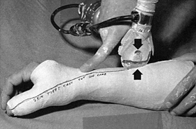
|
Figure 10.25.
When applying a lower extremity cast for a fresh fracture, increased stability can be obtained by applying an ankle traction bandage to which a bucket can be attached. Add enough water to the bucket to stabilize the limb. Maintain a right-angle position of the ankle and proper rotation by balancing the metatarsal heads on your knee. |
or if desired start with Webril. As mentioned, full-length tubular
stockinet is generally not recommended on acute fractures. The general
rule in the use of Webril is to use the smallest width practical for
the limb and to hold the Webril off the limb, keeping it under constant
tension.
The smaller-diameter roll allows the Webril to contour to the limb more
easily. The tension helps apply it smoothly and allows the Webril to
tear when it needs to go around sharp corners such as the heel.
-
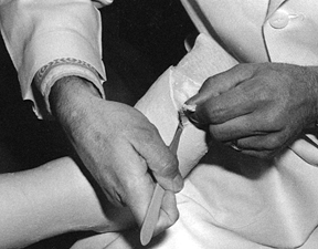
Begin at the metatarsal heads. Cover the
toes so that adequate Webril is present to protect the toes from
plaster and so that a turnback of Webril can be done at the completion
of the cast for padding the end. -
After applying five layers around the
metatarsal heads, begin to progress up the foot, overlapping the Webril
to produce at least two layers of thickness and, depending on the
application, a maximum of four; for most cast applications, two layers
is sufficient. Note that the surgeon has skipped the heel with the
Webril (Fig. 10.26).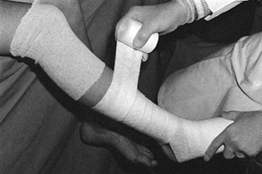 Figure 10.26.
Application of Webril. Hold the Webril off the extremity and apply it
with tension to achieve a smooth wrap two to four layers thick. -
Winding figure-eight Webril around the
heel and instep results in inadequate padding of the heel and too much
Webril in the instep. The former will result in a heel sore, and the
latter will make cutting of the Webril very difficult if the cast needs
to be split. -
Pad the heel with separate, independent
strips of Webril that are torn so that they do not overlap the anterior
aspect of the cast. -
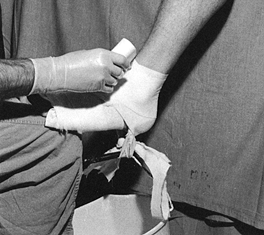
Apply five layers of Webril over bony prominences and the heel if felt is not used (Fig. 10.27). If the Webril does not conform well, simply pull away the loose border, leaving a smooth layer of Webril behind (Fig. 10.28).
![]() Figure 10.27. Pad the heel with separate strips of Webril. Do not use a figure-eight wrap, which places too much Webril over the instep.
Figure 10.27. Pad the heel with separate strips of Webril. Do not use a figure-eight wrap, which places too much Webril over the instep.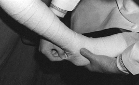 Figure 10.28. When applying Webril, loose edges can be smoothed by simply pulling them away.
 -
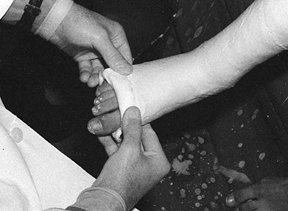
Carry the initial short-leg section as
high as the tibial tubercle, wrapping the Webril well above the
patella. The padding shown in Fig. 10.29 is also suitable for application of a Sarmiento short-leg walking cast.![]() Figure 10.29. The Webril padding has been completed.
Figure 10.29. The Webril padding has been completed.
-
Fill a plaster bucket with clean, tepid
water (70° to 75°F). If considerable molding is necessary, or if a
fracture must be reduced within the plaster, use cold water. If a fast
setting time is desired, water up to 95°F can be used. Avoid water over
this temperature, as the hot water combined with the exothermic
reaction of the plaster may be hot enough to injure the skin. -
Assemble all the plaster needed to apply
the cast before dipping any plaster in the water. For a short-leg cast
on an average 70 kg male, one 4-inch roll for the foot and three 6-inch
rolls for the leg usually suffice. To reinforce the bottom of the cast
or to add a walker, 10 to 15 thicknesses of a 5 × 15-inch splint,
overwrapped with a portion of a 4-inch roll, suffice. -
If the water temperature is cool and the
surgeon applying the cast is skilled, all the plaster rolls can be
dipped simultaneously. All the rolls will set nearly simultaneously,
providing ideal bonding between the layers of plaster. If warmer water
is used or if the applier is less skilled, dip the rolls in sequence;
preferably, have an assistant dip them. -
Move rapidly to allow adequate time for rubbing in the plaster and molding.
-
Turn back a tail on the plaster gauze to
help identify it after the plaster is wet. Dip the roll vertically into
the water. The water must be deep enough to cover the
P.240
plaster
rolls even after the several rolls are dipped. Be sure the water is
clean: water that is cloudy with plaster of Paris from previously
applied casts will accelerate the setting of the plaster. -
Let the rolls stand in the water until no more bubbles rise from the roll (Fig. 10.30).
If several rolls were dipped simultaneously, lift them all out at once
and, without squeezing, allow them to drain vertically on the tabletop.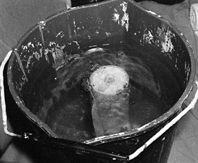 Figure 10.30.
Dip the plaster rolls vertically in a bucket of clean water at 70° to
75°F; allow the roll to soak until all bubbles finish rising from it. -
Take the first roll to be used, grasp it
at both ends, and squeeze it between your palms like an accordion. This
technique will express excess water out of the plaster without
distorting the roll and without losing excess plaster from the gauze (Fig. 10.31).![]() Figure 10.31.
Figure 10.31.
Gently squeeze the water out of the roll by accordioning it from either
end. Twisting or manipulating the roll will result in excessive loss of
plaster. -
Do not twist or overmanipulate the rolls;
twisting them makes them more difficult to work with and it squeezes
excess plaster out of the outer layers of the roll. The assistant, if
present, should hand the roll to the surgeon with the free end exposed
and readily available. -
The general principle in applying plaster
is to use the widest roll that can be applied to the extremity in a
practical manner. In this way, the plaster is applied rapidly with a
minimum of seams. -
Begin with the 4-inch roll around the
metatarsal heads. Apply it distally to the middle of the toes. Use the
4-inch roll entirely on the foot. As much as possible, allow the
plaster to roll on the surface of the extremity. -
Push the roll; rarely if ever pull it.
Usually it is possible to change the direction of the plaster not by
picking up the roll but simply by taking a tuck. For extreme direction
changes, it may be necessary to pick up the roll, but avoid pulling the
plaster (Fig. 10.32). Once the plaster is
started in a figure-eight wrap around the foot and up around the lower
ankle, it will usually seek its own course and nicely cover the foot
without any special effort to change its direction.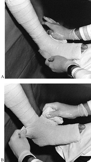 Figure 10.32. A:
Begin with a 4-inch roll at the metatarsal heads; use this roll on the
foot and ankle. Notice that the plaster roll is pushed, not pulled. B:
To change the direction of the roll, place the leading edge in the
direction you want the roll to go. This maneuver produces a loose
corner of plaster, seen here in the surgeon’s left hand. Take a tuck
with the left hand and smooth it down on the posterior aspect of the
leg. For sharp changes of directions, pick up the roll with the right
hand, but in general leave the roll on the extremity. -
Next, take a 6-inch roll, begin on the
foot, and move rapidly up the leg. Apply a single layer of plaster all
the way to the knee. The art of rolling plaster smoothly and skillfully
now comes into play. If the plaster roll begins to progress upward on
the extremity at too sharp an angle, it must be brought back to a
transverse direction around the limb by taking a tuck. Do so by sliding
the fingers of the assisting hand underneath the edge of the roll
closest to you and gently sliding the plaster back to a horizontal
relationship to the longitudinal axis of the limb and then smoothing
out the tuck produced. It is best to place tucks over soft tissue
rather than bone (Fig. 10.33). When crossing joints on their concave surface, slide the roll so that it passes smoothly over the concavity.![]() Figure 10.33.
Figure 10.33.
On the midportion of the limb, take tucks by slipping the hand under
the near edge of the plaster and sliding it until it is transverse to
the long axis of the limb. Smooth out the tuck posteriorly and continue
rolling. -
Avoid pulling the edge of the roll into
the angle of the instep, popliteal fossa, antecubital fossa, or other,
similar areas. After each roll is applied, thoroughly rub in the
plaster until the gauze pattern can no longer be seen. Rubbing ensures
that the layers will unite into one solid, strong layer of plaster,
rather than be laminated. This difference is illustrated in Figure 10.34.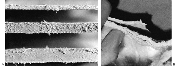 Figure 10.34. A:
These cross sections from well-molded splints show no evidence of
lamination. The layers of plaster have consolidated into one solid
piece. B: In this inadequately molded cast, the layers have laminated and are peeling apart, producing a very weak cast. -
Once enough plaster has been applied,
thoroughly rub the cast in and mold the plaster. Special three-point
molding may be necessary to maintain fracture position. Do this type of
molding with the flat of the palm so that the areas of molding are
broad, with the compression distributed over a broad area of soft
tissue. -
Try to avoid any direct pressure on bony prominences unless the area is well padded.
-
Do not use your fingers or fingertips;
they dent the plaster, producing areas of high pressure. Molding
pressures must be gentle; hard molding nearly always results in skin
problems and pain. -
Plaster applied to the foot will set
first (because it was applied there first). Begin molding distally.
Mold to match the arch of the foot, restoring both the longitudinal and
transverse arches (Fig. 10.35). Then gently
mold the plaster with your palms from anterior to posterior to bring
out the relief of the malleoli. This molding provides a snug fit to the
anterior aspect of the leg, which provides support for the tibia. It
pushes more plaster to the posterior aspect of the cast, creating a
channel for the Achilles tendon and posterior muscles to function,
making a more functional cast (Fig. 10.36).![]() Figure 10.35.
Figure 10.35.
Once all the plaster has been applied and rubbed in, begin molding at
the foot. Restore the longitudinal and transverse arches of the foot.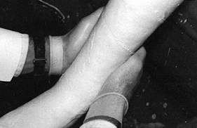 Figure 10.36.
In the region of the ankle and shaft of the tibia, gently pull the
plaster with the palms of the hands from anterior to posterior to mold
it carefully about the malleoli and secure a snug fit to the shaft of
the tibia. -
Stop the molding as soon as the plaster
begins to set—you will feel it stiffen—to avoid cracking the plaster or
producing buckles in the cast. Let the plaster come to a firm set. If
splints are to be used to reinforce the cast, apply them between the
next-to-last and the last roll of plaster, thereby incorporating them
into the cast. The use of splints is discussed in detail later in this
chapter.
not break when handled or set on a padded surface (usually 7–10 min
after dipping of the plaster), trim the ends of the cast.
-
I prefer to use a disposable #10 or #20
blade. It is quick, produces a very smooth edge, and is much more
effective than a cast saw on a “green” cast. If the cast is allowed to
dry, then a cast saw must be used. Take care
P.242
to
avoid cutting the patient or yourself when using a knife. A cast of
appropriate thickness is easy to trim, is not too heavy, and does not
give off too much heat during setting. In casts for the lower
extremity, the average thickness should be about ¼ inch on
nonreinforced surfaces and no more than 5/16 inch or so on reinforced surfaces. -
The trick to trimming with a knife is to
make a cut in the edge of the plaster and produce a corner that the
fingers can grasp easily. Set the blade into the cut and pull the
plaster against the knife blade while gently pushing down with the
blade; the plaster will usually cut quite easily. If you find that you
must push considerably with the knife, get a new blade or change to a
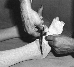
cast saw to avoid injuring yourself or the patient (Fig. 10.37).![]() Figure 10.37. A green cast is easily trimmed with a disposable #10 or #20 blade, following the instructions in the text.
Figure 10.37. A green cast is easily trimmed with a disposable #10 or #20 blade, following the instructions in the text. -
In standard short-leg casts, trim the
cast to the base of the toes, leaving the metatarsal heads covered. If
necessary, spread the cast at the end to allow full range of motion for
the toes. Toe plates are generally contraindicated as they restrict
motion of the toes. Use them only if the cast is being applied for toe
pathology.
-
Turn a cuff of Webril to cover the plaster and then turn back the tubular stockinet (Fig. 10.38).
If stockinet is not used, cut the plaster and Webril on the lateral
aspect of the fifth toe and medial aspect of the great toe, turning
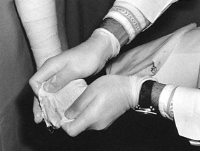
back the cuff to an appropriate level.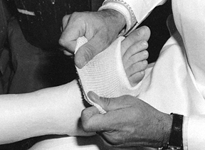 Figure 10.38.
When tubular stockinet is used, trim the edge of the cast just distal
to the metatarsal heads, turn back a layer of Webril to pad the end of
the cast, and turn back the tubular stockinet, securing it in place
with a few wraps of circumferential plaster. -
Then incorporate either the stockinet or the Webril with a few turns of a fresh roll of plaster (Fig. 10.39).
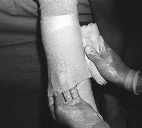
![]() Figure 10.39.
Figure 10.39.
If tubular stockinet is not used, cut the Webril and plaster on the
lateral and medial aspects and turn it back to produce a soft cuff,
which is then secured with a few turns of fresh plaster. -
When trimming surfaces such as the
abdominal hole in a spica cast where it is not easy to use a roll, the
Webril or stockinet can be adhered to the cast by first stapling it in
position (using a staple short enough that it will not penetrate the
full thickness of the cast). Then trim with two layers of splints cut
to fit the area, or take a sloppy, wet roll of plaster and coat the raw
Webril, thus incorporating it into the surface of the cast.
I have modified the trimming of the upper end of Sarmiento’s cast: I
begin the trim proximal to the patella and carry it directly
posteriorly to the hamstrings. A channel for the hamstrings is then
created sufficiently deep to allow the flexion desired. Notice that the
cast is molded above and extends almost horizontally posteriorly over
the femoral epicondyles (Fig. 10.40C). The
upper edges are bent away to allow full extension of the knee. On the
front view, notice that the cast is molded in well over the epicondyles
of the femur. Although there is a mold over the patellar tendon, it is
not emphasized. The mold over the medial and lateral condyles of the
tibia, and around the epicondyles of the femur, is more important to
obtain good rotational control proximally. Note that the cast is
trimmed out posteriorly to allow good knee flexion without impingement
on the hamstring tendons. Avoid pressure over the common peroneal nerve
at the fibular head. I prefer this molding and trimming of the
Sarmiento cast to that more traditionally described because
it
is technically simpler to do and resembles the configuration of a
patellar tendon suspension (PTS) below-knee prosthesis, which provides
better molding at the knee.
 |
|
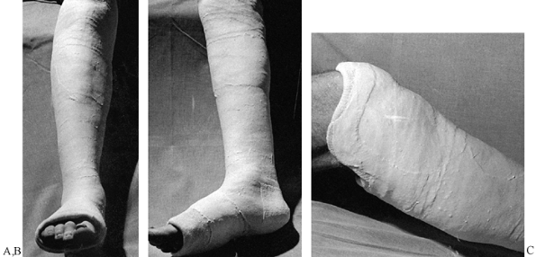
Figure 10.40. Completed Sarmiento short-leg weight-bearing cast. A:
Frontal view. Notice the contouring of the cast to the anatomy of the leg, the flat molded surfaces over the subcutaneous borders of the tibia and anterior compartment, and the spacious fit around the toes. B: Side view. Notice that the cast has been flattened over the upper gastrocsoleus area to push the tibia forward in the cast. This increases containment and improves the hydraulic support for the fracture. C: My modification of the trimming of the upper end of Sarmiento’s cast. |
whether the initial cast was applied at the standard short-leg level at
the tibial tubercle or was extended to a Sarmiento-type cast for a
better hold. As long as Webril has been applied well proximal to the
plaster, then the next plaster rolls can simply be applied over the
upper end of the short-leg cast and then extended up the thigh.
-
Some surgeons prefer to petal the upper
end of the cast and turn the plaster back, placing an additional roll
of Webril beneath it to ensure that padding is adequate at the upper
end of the cast (Fig. 10.41). The petals are then turned down and the plaster for the thigh portion is applied.![]() Figure 10.41.
Figure 10.41.
Extending a short-leg cast into a long-leg cast. If enough Webril has
been applied above the short-leg cast, it can be extended into a
long-leg cast by simply applying plaster over the upper end of the
existing cast. If padding is inadequate, some surgeons prefer to petal
the cast as shown here, placing more padding beneath the plaster and
then turning the petals back down, incorporating them into the cast. -
Three or four 6-inch rolls are usually
sufficient for the average-size man, and a 10-layered 5 × 30-inch
splint is often useful to reinforce the knee. I prefer to apply the
splints as a V, with the point of the V placed in the
P.245
region
of the tibial tubercle and the vertical arms carried up the medial and
lateral aspects of the knee. The splints are thus at right angles to
the plane of flexion and extension of the knee and provide maximum
reinforcement. Carry the average long-leg cast proximally over the
prominence of the greater trochanter and leave at least a handbreadth
below the groin to facilitate perineal care. This space makes it
simpler for the patient to sit on a toilet, yet the cast still provides
good support proximally. The molding for this cast is well described in
Chapter 24 on fractures of the tibia and fibula. A well-molded, completed cast for weight-bearing is shown in Figure 10.42.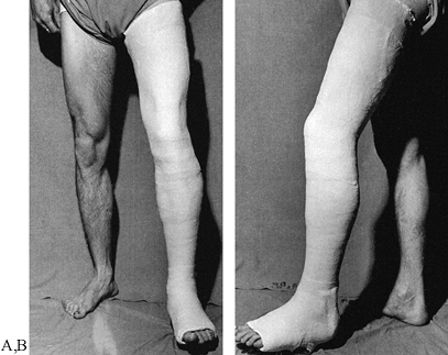 Figure 10.42. Long-leg weight-bearing cast. A:
Notice that the below-knee portion of the cast is molded exactly as
described for the Sarmiento cast. Just above the femoral epicondyles
and patella, mold the plaster on the medial and lateral sides to
provide good rotational hold about the distal femoral condyles. Molding
pushes plaster anteriorly and posteriorly, creating channels for the
hamstring and patellar tendons. Mold the plaster proximally like a
quadrilateral socket. Notice the oblique angle that carries the plaster
up to the level of the greater trochanter. B: Notice the anatomic molding of this cast. The knee is in about 5° to 7° more flexion than necessary. -
Apply walking casts with the knee nearly
in full extension. Avoid hyperextension or full extension, which may
result in knee discomfort. Usually 5° of flexion is appropriate.
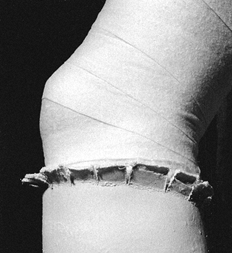
The walking shoe is removable; the patient can take it off at night to
make the cast lighter and to avoid getting the bed linens dirty. A
walking shoe also provides some protection for the foot portion of the
cast.
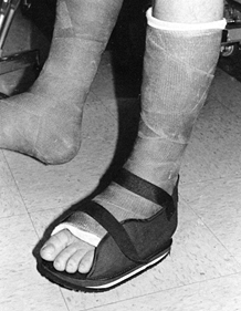 |
|
Figure 10.43. Commercial-type walking shoe.
|
is an excellent alternative. Its smaller surface area allows the foot
to twist on the floor more easily than with cast shoes (Fig. 10.44).
Because it places the patient’s foot somewhat higher off the floor, the
walking heel gives a wider range of motion for the knee during gait.
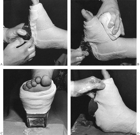 |
|
Figure 10.44. Applying a walking heel. A:
Before trimming the cast, apply a 10- to 15-layer splint along the plantar aspect of the foot and up the back of the heel. Place the walking heel at the mid foot and pack plaster underneath it to place it at right angles to the foot in both the longitudinal and frontal planes. B: Secure the walking heel to the cast with a 4-inch roll of plaster, thoroughly incorporating the heel. C: The completed walking heel is at right angles to the longitudinal axis of the leg. D: The walking heel is in the middle of the foot. If the heel is placed too far anteriorly, the patient will back-knee; if placed too far back on the heel, the patient will contact on the forefoot and break down the cast. |
the foot free—in essence, a cylinder cast of the leg. It is useful when
full foot and ankle motion is desired and a mid-shaft fracture of the
tibia and fibula is fairly stable. Because these casts tend to slip
down and cause pressure on the foot, a heel cup and ankle hinge are
usually attached for suspension (Fig. 10.45).
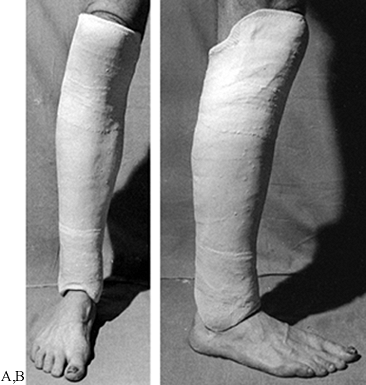 |
|
Figure 10.45. A:
A Delbet walking cast is applied in exactly the same manner as a Sarmiento cast. Distally, the foot is left free, and the cast is molded carefully over both malleoli and left high enough above the instep and heel to allow full ankle motion. Suspension usually requires application of an ankle hinge with a heel cup. B: This side view shows the molding over the malleoli. |
control is not of great concern. Generally, it is used as a weight-bearing cast; therefore, the foot is left free.
second table or stool with the lateral or medial side of the knee
downward, depending on which side has the ligament injury. In a medial
collateral ligament injury, place the lateral side downward. Gravity
automatically reduces the knee joint (Fig. 10.46A). This is also a good position for control of cruciate ligament instability.
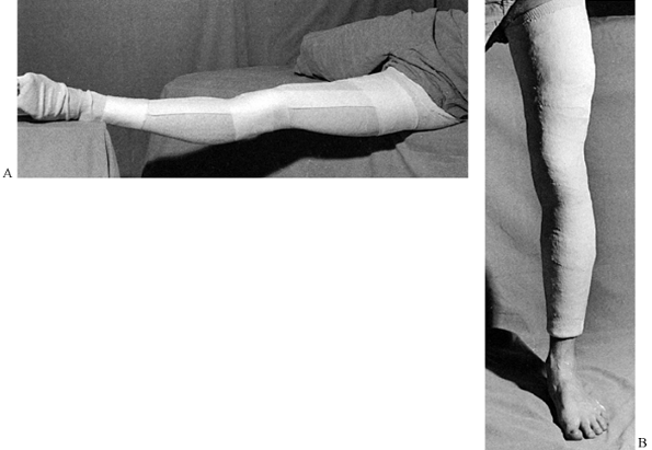 |
|
Figure 10.46. Cylinder cast. A:
For a medial collateral ligament injury, place the foot on a supporting surface and rotate the limb so that the lateral side is downward. Gravity therefore closes the medial joint line. Use the opposite position for a lateral collateral ligament injury. In this case, a skintight cast is used by rolling a snug stockinet over the leg. Use Webril to pad around the bony prominences at the ankle and the knee, and trim the cast at the hip. Place two layers of Webril down the anterior aspect of the cast for removal with a cast saw. The plaster is now applied directly over this padding and the stockinet. B: The completed cylinder cast has been carefully molded to the leg, particularly above the femoral condyles to provide suspension. Note that the cast stops well above the malleoli so that if it drifts downward, it will not contact the malleoli and cause pressure sores. |
ointments such as Ace adherent or tincture of benzoin can be applied to
the extremity and then a snug tubular stockinet rolled over it to
adhere the cast to the leg. Strips of adhesive tape on the leg turned
up into the cast from the lower end serve the same purpose. All of
these methods have the disadvantage of placing a chemical adherent
beneath the cast, which may elicit an allergic response. In the lean
athletic leg, good molding of the cast (Fig. 10.46B) will result in adequate suspension. In obese patients, suspenders may be necessary to keep the cast up.
the knee, either polycentric metal hinges or plastic hinges. The ankle
can be hinged as well. Rotational control, particularly for treatment
of fractures of the middle to proximal femur, can be facilitated by
adding a hip hinge. The cast-brace was developed during the Vietnam War
for the treatment of fractures of the shaft of the femur. It can also
be used for treatment of tibial plateau fractures. It is most useful
for treatment of supracondylar fractures of the femur. Shaft fractures
can also be treated, but the incidence of shortening and malunion is
significant. It has even been extended to the treatment of
subtrochanteric fractures of the femur.
specialized equipment needed for application of a long-leg cast-brace:
two types of hinges, a polycentric steel one and a polycentric plastic
one; a quadrilateral plastic socket for the upper thigh and plastic
heel cup with plastic ankle hinge; a cast-brace stocking (extra heavy
and specially padded); adhesive synthetic pads and an elastic wrap for
the knee; corset-bending irons for adjusting the knee hinges; and a jig
and hose clamps for holding the hinges in proper position.
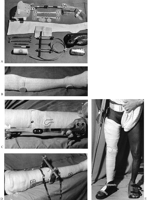 |
|
Figure 10.47. Long-leg cast-brace with hip hinge. A: The specialized equipment needed for application of a long-leg cast-brace. B: Special heavy stockinet is applied over the limb and the elastic sleeve over the knee. C: The center of a metal polycentric knee hinge will be placed directly over the epicondyles. D: Apply the hinges to the cast with the jig and hose clamps and incorporate them well into the cast. E: The completed cast-brace.
|
-
Apply the special heavy stockinet over the limb and the elastic sleeve over the knee (Fig. 10.47B).
-
Place synthetic adherent pads over the
fibular head and malleoli. A plastic quadrilateral socket at the upper
brim may or may not be used. -
Apply a well-molded long-leg cast as already described, or apply the cast in a leg and thigh section (Fig. 10.47C).
-
Carefully locate the medial and lateral
epicondyles of the femur and mark them with a pen. The center of a
metal polycentric knee hinge will be placed directly over the
epicondyles. -
Carefully mold the hinges to fit the
lateral and medial sides of the leg, avoiding impingement of the metal
on bony prominences. Both hinges must be located symmetrically and
parallel to each other, in line with the knee’s axis of bending. -
Apply the hinges to the cast with the jig and hose clamps and incorporate them well into the cast (Fig. 10.47D).
nailing, cast-braces are little used today in North America for the
treatment of fractures of the shaft of the femur. Interested readers
will find the articles of Mooney (61,62) and others (20,36,46,55,58)
worth reading, particularly for details of the technique of
application. Many fractures in the lower extremity cannot be treated by
internal fixation, so we use cast-bracing with reasonable frequency. It
should be part of the repertoire of every orthopaedic surgeon treating
lower-extremity fractures.
V-shaped crossings, resembling a spike of grain (the meaning of the
Latin word spica); this configuration is
produced by a figure-eight wrap around the torso and then around the
limb. With the advent of internal fixation, spica casts are little used
in adults, but they are commonly used in children for the treatment of
hip dysplasia, for postoperative immobilization, and for the treatment
of fractures.
greatly facilitates the application of the single-leg hip spica cast in
children. Sometimes spica casts can be applied with just heavy
sedation, but usually an anesthetic is required.
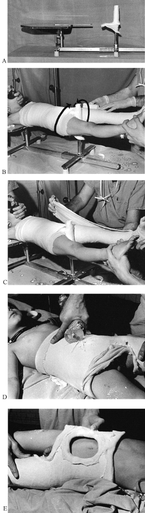 |
|
Figure 10.48. Pediatric hip spica cast. See text for details.
|
-
Support the child’ shoulders and upper thorax on the table and the pelvis on the perineal post, which should be well padded.
-
A single assistant can support the legs and apply any traction necessary (Fig. 10.48B).
-
Trimming of the cast is greatly
facilitated by first applying tubular stockinets. One size of stockinet
will be necessary for the torso and another for the lower extremity. -
Thoroughly pad with Webril. Felt is
usually unnecessary in children, but small ¼-inch-thick pads can be
placed over the anterior superior iliac spines, around the rib cage,
and over the sacrum if necessary. -
If only one surgeon is available, it is
usually easiest to apply the long-leg cast first as a cylinder from the
ankle to the hip, carefully molding it and allowing it to set. The
direction of the spica wrap used to move up onto the torso is
illustrated in Figure 10.48B. -
Then the cast can progress up onto the
torso. If two sets of hands are available, the torso and long-leg
portion can be applied simultaneously, which provides better
integration between the long-leg cast and torso portion. Extra padding
around the upper edge of the cast at the ribs makes it more comfortable.
outlined as follows. In general, the cast should extend from the
xiphoid process to the metatarsal heads.
-
The initial rolls of plaster should be fairly thin (usually three or four layers) (Fig. 10.48C).
-
To avoid a cast that is too heavy and to
reinforce it where the stress is greatest, apply five-thickness splints
on the lateral aspect of the extremity, extending up onto the torso.
Also, wrap a splint around the upper chest cage and around the pelvis
to reinforce the edge of the cast, which will become the border for the
perineum and buttocks. -
Thoroughly wrap these in with another series of rolls of plaster, taking care to not make the cast too thick.
-
Create a generous hole over the abdomen
to make breathing easy and to ventilate the cast. To facilitate the
abdominal hole, cut a star with the cast saw (Fig. 10.48D). It is then easy to bend the flaps upward and cut them off with either the cast saw or a sharp scalpel. -
Trim the cast well above the perineum to
avoid soiling. Over the buttocks, allow adequate room for bowel
movements; do not trim the cast above the prominence of the sacrum,
however, as the patient’s buttocks will protrude out of the cast
posteriorly and develop pressure sores on the upper sacrum. -
In a single-leg hip spica cast, trim the
opposite hip to allow flexion to 90°. Carefully trim the cast to make
it comfortable. Softening the upper edge of the cast with a cast bender
after the plaster has set makes it more comfortable. -
When the cast has been completed, apply
2- to 3-inch-wide plaster splints to trim and seal the tubular
stockinet down to the cast. (The cast in Fig. 10.48E
is about 2–3 inches below the xiphoid, which is somewhat too low. Most
patients are more comfortable if it is at the level of the xiphoid.)
hip spica cast are the same as those for the children’s. In adults, a
fracture table is essential. Figure 10.49A
shows an anesthetized patient on the fracture table with a long-leg
cast already applied to the left lower extremity to stabilize an
unstable knee.
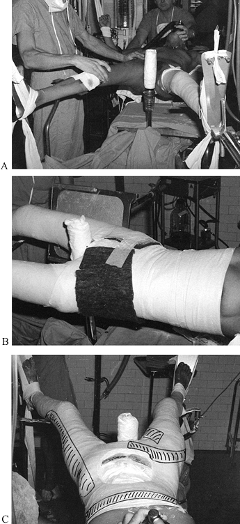 |
|
Figure 10.49. Adult double-hip spica cast. See text for details.
|
-
Place the patient supine on a fracture table (Fig. 10.49A).
Note the padded perineal post and special foot plates. Plaster can be
applied directly over the foot plates, and they can then be slid out of
the plaster; this is a very convenient feature. The knees are held in
10° or so of flexion by knee supports, which are also slid out of the
cast after application. -
In adults, use felt to pad all bony
prominences. A single sheet of ¼-inch-thick felt around the pelvis
provides good padding over the sacrum and anterior superior iliac
spines (Fig. 10.49B). Rubbing the felt over the
end of a smooth-ended pole or stick will produce a small bulge in the
felt that fits nicely over the anterior superior iliac spine or other
bony prominences. Run a similar sheet of felt about 3 inches wide up
the entire length of the spine, and apply another sheet around the
upper edge of the cast. -
The nearly completed cast before application of the feet is shown in Fig. 10.49C.
Trimming has yet to be completed, although the abdominal hole has been
cut out. Shown in the photograph are the locations of the splints used
to reinforce the cast. The cast should consist of an initial layer of
plaster of about four thicknesses, overlaid by splints, and then
thoroughly incorporated with rolls. The reinforced regions should be
about 5/16–3/8 inch thick and the nonreinforced portions about ¼ inch thick.
adults. Sometimes it is necessary to immobilize the hip and femur in a
hip spica cast that will be used for walking. These casts fit much
better if they are applied with the patient in the weight-bearing
position (Fig. 10.50A).
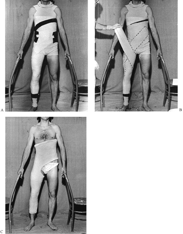 |
|
Figure 10.50. Adult single-leg weight-bearing hip spica. See text for details.
|
-
I find it easiest to have the patient stand between two chairs, using the chairs for support.
-
Apply a tubular stockinet of the appropriate diameter.
-
Pad with Webril and felt as previously
described. Notice that the cast will stop well above the ankle to avoid
ankle impingement if it settles. -
Make the upper edge of the cast oblique,
high on the side opposite the extremity to be immobilized, and low on
the rib cage on the immobilized side. The midportion should cross the
xiphoid. Keeping the cast high on the chest wall opposite the
immobilized extremity counterbalances the weight of the leg and makes
the cast more comfortable. The oblique angle makes it easier for the
patient to sit. -
Allow plenty of room for the perineum and the function of the opposite hip.
-
First apply rolls of plaster to a
thickness of about four layers; then apply reinforcing splints and more
rolls to incorporate them (as described previously). Notice the
direction of the splints (Fig. 10.50B). -
The completed cast is illustrated in Figure 10.50C.
back pain, although it is used less often today because of the
increasing sophistication and effectiveness of orthotic appliances. The
purpose of the cast is to provide three-point fixation, straightening
hyperlordosis of the lumbar spine and increasing intra-abdominal
pressure by compression on the abdomen. Generally, the patient should
remain fairly active and do both abdominal and spinal
muscle-strengthening exercises while in the cast.
-
Stand the patient about 18 inches from a
table and have him lean over, rest his hands on the table, and suck in
his abdomen, rounding up his back (Fig. 10.51A).![]() Figure 10.51. Flexion body jacket. See text for details.
Figure 10.51. Flexion body jacket. See text for details. -
Apply a tubular stockinet tied over his shoulders and extending down onto his legs.
-
Wrap the torso thoroughly with Webril; felt is usually not needed.
-
Apply circumferential rolls of 6- or
8-inch plaster from well below the hips to the xiphoid and well up onto
the back. Splints up the spine and across the back are useful in
reinforcing the high posterior portion of the cast. -
Apply the cast rapidly so that three-point molding can be applied, as illustrated in Fig. 10.51A. The direction of the molding is indicated by the arrows.
-
The completed flexion body jacket (Fig. 10.51B)
extends well down over the buttocks to the gluteal crease and extends
to about T-4. The abdominal portion is narrower but well molded to
produce abdominal compression over the mid abdomen.
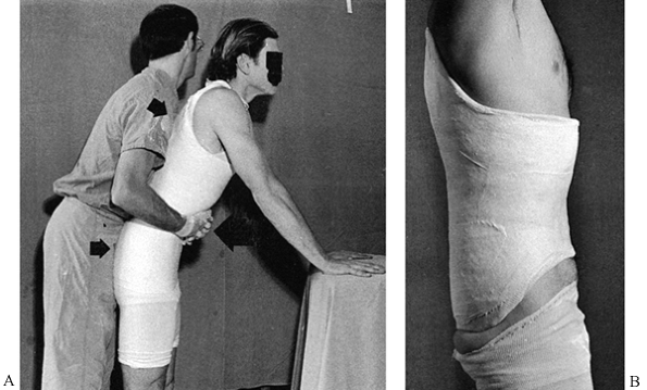
treatment of compression fractures of the spine in the region of the
thoracolumbar junction. Most surgeons apply them by placing the patient
on a fracture table in the supine position on Goldthwait irons, steel
bands that can
be
adjusted to produce a desired degree of hyperextension of the spine.
This is the simplest and most controlled method for applying this cast.
canvas strap of a Bell orthopaedic table with the feet suspended from
the overhead frame (Fig. 10.52). The fracture
is placed directly over the middle of the canvas strap, and the strap
is slowly loosened until the desired reduction is obtained. The cast is
then applied and the canvas strap pulled out of the cast.
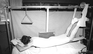 |
|
Figure 10.52.
Use of a bell table and canvas strap for reduction of a thoracolumbar junction fracture and application of a hyperextension body jacket. |
-
Suspend the patient between two tabletops and allow her back to hyperextend to a comfortable position.
-
Apply the cast as previously described.
The plaster must be brought down over the pubic symphysis and high on
the chest just short of the sternal notch. As the cast sets, these two
areas must be molded as illustrated in Fig. 10.53A.![]() Figure 10.53.
Figure 10.53.
Watson-Jones method for reduction of a compression fracture of the
spine at the thoracolumbar junction with application of a
hyperextension body jacket. See text for details. -
Notice that the completed hyperextension body jacket (Fig. 10.53B)
is low over the pubic symphysis and high on the chest to maintain the
position of hyperextension. Posteriorly, it extends from the gluteal
crease to the mid-thoracic spine. For comfort, place an abdominal hole.
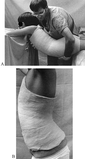
casts are now rarely used, but they may provide better immobilization
for unstable injuries at C-1–C-2. A loose halo jacket may impart
undesired motion to the upper cervical spine when it is connected to a
halo; the Minerva avoids this situation. In most situations, the
Minerva is applied with the patient supine on an orthopaedic table in
gentle head-halter traction. If the cervical or upper thoracic spine is
stable (for example, after internal fixation) and protection until
healing is desired, a better-fitting cast can be obtained by applying
the cast with the patient in the upright position. Do it only after the
patient has been mobilized somewhat, to avoid postural hypotension.
-
Seat the patient comfortably on a stool next to the fracture table (Fig. 10.54A).
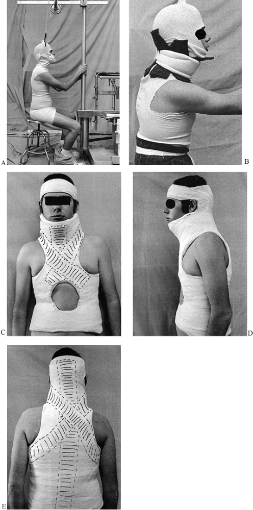 Figure 10.54. Minerva jacket. See text for details.
 -
Use the overhead traction assembly to
provide head-halter traction to support the cervical spine in the
desired position, which generally is neutral. -
Supervise the patient carefully, because he may faint from postural hypotension (an assistant can be assigned this job).
-
Padding around the chin, occiput, and neck is important (Fig. 10.54B).
Take a ¼-inch piece of felt wide enough to extend from the acromion to
the lower edge of the ear, and from the sternal notch to somewhat
beyond the chin. Make it long enough to go around the entire neck. Make
transverse cuts alternating from side to side so that it fits nicely
around the neck, as illustrated. Hold it in place with a soft cervical
collar, which will be incorporated into the cast. -
Put a circumferential piece of felt
around the iliac crest and add a third piece along the spine if you
wish. If a cervical collar is used, the cervical traction is usually
not necessary. Use the basic principles for plaster application
outlined for the spica cast. -
Apply the body jacket and the occipital portion of the cast.
-
After it has set, add the headband. Use
4- and 6-inch rolls of plaster to obtain a base layer, and then apply
splints as illustrated on the cast (dotted lines, Fig. 10.54C). -
Apply a 15-layer-thick splint on the
entire spine up onto the occiput; this splint forms the backbone of the
cast and gives it stability. Once it sets, the head will be secured to
it. -
Secure the head by wrapping a
circumferential roll of 3-inch plaster around the head, connecting the
head portion firmly to the previously applied occipital portion. -
Trim as indicated in Fig. 10.54C, Fig. 10.54D and Fig. 10.54E (the front, side, and posterior views). Notice the location of splints drawn on the cast.
spica cast is less commonly used for the shoulder. A spica cast is more
versatile, however, and often more comfortable than an abduction
shoulder brace. It is used to treat humerus fractures, to protect
soft-tissue injuries about the shoulder, and in surgical repairs of the
shoulder and proximal humerus.
-
I usually apply this cast using a regular
operating table and a “slippery stick,” a piece of hardwood about 3–4
inches wide, 1 inch thick, and at least 6 feet long, which has been
sanded into an ellipsoid shape, thicker in the middle and tapering to
the sides. The stick is highly varnished and can be coated with mineral
oil or lubricant jelly to make it slide more easily. -
Place the stick under the patient’s spine
and head. A solid stool or part of the anesthesia machine can be
brought in to support the head of the stick. With two assistants
holding the patient’s arms on both sides to balance her torso, the
operating table can then be slid toward the feet until it just supports
the buttocks. The torso is left completely suspended in space on the
stick. -
Before this maneuver, it is often wise to
apply a long-arm cast, which will subsequently be incorporated into the
spica cast. Keep the long-arm cast light, as the reinforcement
necessary to connect it to the body jacket portion will make it quite
heavy. Another method is to use the versatile attachments provided by a
Chick-Langren orthopaedic table to completely preposition the patient
for the shoulder spica cast (Fig. 10.55A). The basic principles of padding are used as described for other jackets surrounding the torso.![]() Figure 10.55. Shoulder spica cast. See text for details.
Figure 10.55. Shoulder spica cast. See text for details. -
The completed cast extends well down over the iliaccrest (Fig. 10.55B).
The proper length is important for stability. If the cast is left too
high, the weight of the arm will cause it to swing, and the edge of the
cast will dig into the rib cage or the top of the iliac crest, causing
pain. Note that the side of the cast opposite the immobilized arm is
kept high to provide support for the arm. -
Spica casts can break easily at the
junction of the extremity and the body portions of the cast; therefore,
a reinforcing rod, as used here, is useful. It can be made by rolling
up newspaper and covering it with plaster; a wood stick covered with
plaster can be used as well. A similar stick should be used between the
legs on a double hip spica or a 1½ hip spica. -
Figure 10.55B
shows the position of the splints in this cast. Once early healing
occurs, the top of the cast can be removed and exercises can begin (Fig. 10.55C).
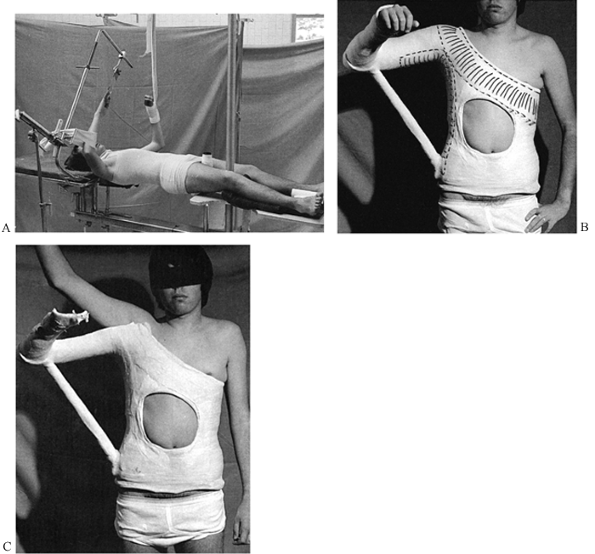
is useful for treating unstable fractures of the clavicle that require
hyperextension of the two shoulders to maintain position. It can also
be applied to one shoulder, incorporating the upper arm if necessary.
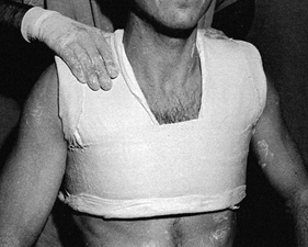 |
|
Figure 10.56.
The plaster bolero is applied using splints across the top of the shoulders and a circumferential wrap around the chest. This bolero has not yet been trimmed. |
-
Apply the bolero with felt and good Webril padding over the fracture site.
-
Mold it carefully and then trim it to allow as much shoulder motion as desired.
a soft-tissue dressing to immobilize the shoulder or humerus. When
combined with a sugar-tong splint on the humerus, it is very effective
for immobilizing fractures of the shaft of the humerus. Otherwise, it
is the utilitarian method for immobilizing the shoulder when secure
fixation is desired. Overwrap the soft Velpeau with plaster if better
immobilization is desired or if patient compliance might be a problem.
-
Place abdominal pads or other padding into the axilla and over the skin of the arm and the chest wall to avoid skin irritation (Fig. 10.57A). Powder with baby powder or cornstarch to absorb moisture from perspiration.
![]() Figure 10.57. Soft and hard shoulder Velpeau dressings. See text for details.
Figure 10.57. Soft and hard shoulder Velpeau dressings. See text for details. -
Using a 6- or 8-inch-wide bias-cut
stockinet, begin on the chest wall below the arm and bind the arm
gently to the chest with a circumferential wrap (front view, Fig. 10.57B; back view, Fig. 10.57C). After a half-dozen wraps, pass it beneath the elbow and vertically over the ipsilateral shoulder to support the arm. -
Overwrap the bias-cut stockinet with Webril and then overwrap in the same manner with two 6- or 8-inch rolls of plaster (Fig. 10.57D).
-
After application, check at the medial
epicondyle of the elbow to be sure there is no pressure over the
ulnarnerve. In acute fractures of the distal portion of the humerus,
this amount of elbow flexion may not be possible initially due to
swelling. In that case, use a sling and simply bind the arm to the
chest wall in a sling-and-swath technique.
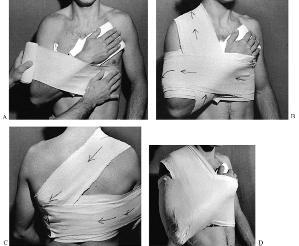
and the base of the finger metacarpals for a host of disorders. The
application of a short-arm cast to maintain the reduction of a
relatively stable Colles’ fracture is shown in Figure 10.58.
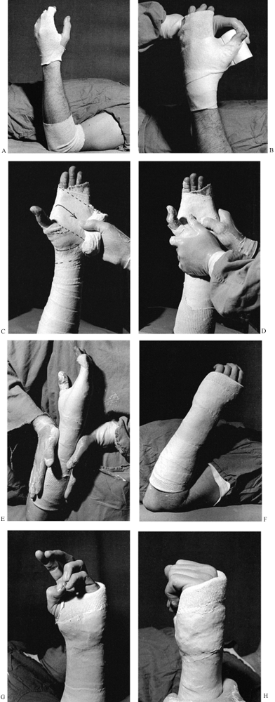 |
|
Figure 10.58. Short-arm cast for immobilization of a stable distal radius fracture. See text for details.
|
-
In stable fractures, place the patient
supine on the treatment table, rest the elbow on the tabletop, and form
the hand as if holding a soft-drink can. -
Apply a tubular stockinet at either end of the cast (Fig. 10.58A).
On the hand, carry the tubular stockinet to the tip of the fingers. I
prefer somewhat more stockinet around the base of the thumb and wrist
than illustrated here. -
For the average-size adult, 3-inch Webril is best for padding (Fig. 10.58B).
Obtaining smooth, adequate padding about the hand can be difficult. Use
a figure-eight wrap; when you encounter the thumb, simply pull the
Webril down over the tip of the thumb, as illustrated, allowing the
thumb to poke through the Webril. This produces a nice layer of padding
around the base of the thumb. -
Carry the Webril distally about 2 cm distal to the prominence of the metacarpal heads.
-
Apply plaster using two or three 4-inch rolls, depending on the size of the limb (Fig. 10.58C).
In small adults or older children, use a 3-inch roll. I do not find it
necessary to use splints, although some surgeons prefer them. A nice
trick for obtaining a smooth wrap around the thumb, palm, fingers, and
wrist is to leave the 4-inch roll at its full width and apply it as a
figure eight around the wrist, with the thumb in one hole of the eight
and the fingers in the other, leaving the roll at full width as it
passes through the palm. The result is a very smooth application of
plaster with very nice coverage of the palm and wrist. The direction of
this wrap is indicated by the dotted lines in the photograph. -
Carry the plaster proximally to the level desired. Apply it rapidly, and thoroughly rub it in (Fig. 10.58D). Try to keep the cast no more than ¼ inch thick.
-
Begin molding by reproducing the transverse arch of the palm, as illustrated.
-
Then mold the forearm to the normal oval shape of the forearm (Fig. 10.58E).
-
Do not stop the cast on the dorsal side
more proximal than the metacarpal heads, as swelling will cause it to
compress the dorsal veins, with resulting increased
P.261
swelling
of the digits. Placing the cast over the prominence of the metacarpal
heads allows these veins to drain through the intermetacarpal spaces. -
How the cast is molded and how far
proximally it is carried at the elbow determine how much motion in
supination and pronation will remain. The more the cast is made into an
oval shape and the higher on the elbow it is carried, the less motion
there will be. -
Trim the completed cast at the elbow
flexion crease to allow full elbow flexion without impingement of the
plaster into the antecubital fossa (Fig. 10.58F). -
When trimming the cast around the hand, first cut the plaster to the desired level with a scalpel (Fig. 10.58G).
Trim the cast on the dorsal side to the prominences of the metacarpal
heads and cut the palmar side down to allow flexion of the fingers to
90° and good apposition of the thumb. -
Turn a Webril cuff over the edge of the
cast, and then cut a small hole in the stockinet for the thumb. Pull
the entire tubular stockinet back over the thumb and palm of the cast
and secure it about the wrist with a few rolls of plaster. This makes
trimming the cast simple and eliminates the need for a bar of plaster
in the first web space. The material on the palm also enhances the grip
for objects. -
Note that restoration of the normal
transverse arch of the palm allows the patient to easily touch the
thumb to the tips of the fourth and fifth fingers. -
The trim around the fingers covers the
top of the metacarpal heads and then inclines forward to allow flexion
to 90° at the metacarpophalangeal joints (Fig. 10.58H).
forearm and wrist when flexion and extension of the elbow, but limited
supination and pronation, are desired. It might be indicated for a
fracture of the radius and ulna where pronation and supination are
thought to be a destabilizing factor, or for postoperative protection
of internal fixation of the forearm, where supination and pronation
must be avoided. Application of this cast (Fig. 10.59) requires a simple modification of the standard short-arm cast just discussed.
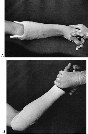 |
|
Figure 10.59. Muenster short-arm cast. A:
The Muenster short-arm cast is applied in the same fashion as the short-arm cast just described, but the cast is carried up onto the distal arm and then subsequently trimmed down to the configuration seen here. Notice that the proximal end of the cast grips the epicondyles of the humerus as in the supracondylar portion of a Sarmiento cast. It is cut out well over the antecubital fossa to allow full flexion of the elbow. B: In this side view, notice the extensions of the cast over the epicondyles and the grip on the back of the olecranon. Trim the posterior aspect of the cast to allow full extension. |
to a carpal tunnel syndrome. In very loose-jointed patients, it may be
necessary to hold the wrist in a position of about 30° to 45° of
flexion, rather than the 90° into which it may fall by virtue of
gravity alone.
-
Apply stockinet and Webril for padding as discussed for the standard short-arm cast.
-
Do not use finger traps to reduce Colles’
fractures, because it is difficult to evaluate the stability of the
fracture while it is hanging in finger traps. -
Carry out the reduction by first applying
countertraction to the humerus. To correct shortening and radial
deviation, pull traction on the thumb with one hand. -
With the other hand, grasp the end of the
radius, placing your thumb directly over the distal fragment at
Lister’s tubercle. Reduce the dorsal angulation and simultaneously
pronate the forearm to reduce the supination, holding traction on the
thumb. This technique maintains correction of length and keeps the
wrist in ulnar deviation. -
Allow the arm to hang passively off the side of the treatment table (Fig. 10.60A)
with the elbow extended. With the hand hanging in this position, it is
possible to determine the degree of remaining dorsal tilt, restoration
of length, and so forth.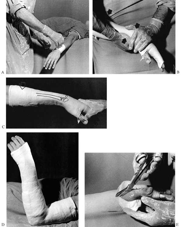 Figure 10.60. Long-arm cast for Colles’ fracture. See text for details.
 -
It may be helpful to have an assistant
gently grasp the fingers and the thumb to open the web space and to
hold the hand ulnarly deviated and the wrist pronated. -
If the fracture maintains good position,
with perhaps slight support on the thumb and fingers by an assistant,
then with three-point molding in a long-arm cast there is a high
likelihood that an anatomic position can be maintained until union
occurs. -
If, however, the fracture shifts into
malposition, it is unlikely that a cast alone will maintain the
reduction. In this case, use percutaneous Kirschner wire fixation, an
external fixator from the radius to the second metacarpal, or a
combination of the two. Occasionally, internal fixation may be
necessary when there is disturbance of the articular surface of the
radius that is amenable to internal fixation. -
Apply the plaster rapidly and smoothly as
for the short-arm cast, then mold the cast gently by reproducing the
forces used to reduce the fracture (Fig. 10.60B). -
Three-point molding is important: One
point of pressure is your thigh, the second is over the dorsal aspect
of the distal fragment (not on the hand), and the third is the
counterpressure point along the palmar aspect of the forearm. All of
these molding areas should be very broad and gentle to avoid pressure
points. The molding is indicated by the arrows. -
In the completed molding of the forearm portion of the cast (Fig. 10.60C),
notice the flat spot in the cast over the dorsum of the distal radial
fragment, which is drawn on the cast. The direction of the molding is
indicated by the arrow. -
Note the smooth broad area of molding along the palmar side of the radius, which is continuous with the curvature of the thumb.
-
In the completed long-arm cast (Fig. 10.60D), Webril rather than stockinet was used to trim the ends of this cast.
-
The elbow is flexed to 90° and the
forearm is moderately pronated. Note the ulnar deviation in the wrist.
An indication of some of the molding that was done after the cast was
applied can be seen by the small wrinkle in the cast on the ulnar side
of the hand. -
When using Webril alone to trim the cast,
a useful method for trimming of both the fingers and the thumb is to
make a longitudinal cut with a pair of scissors or a scalpel along the
radial aspect of the thumb as far proximally as desired, and a similar
cut along the ulnar border of the hand (Fig. 10.60E).
The plaster can then be turned back as illustrated on the thumb and
then captured with a few circumferential rolls of plaster to complete
the molding.
the metacarpals of the hand and for minor wrist injuries. For fractures
of the fourth and fifth metacarpals, I prefer to use an ulnar gutter
splint (described below), but the gauntlet cast is quite useful for
fractures at the base and in the mid shaft of the metacarpals. It also
can be used for the typical boxer’s fracture of the neck of the
metacarpal. In the latter case, the cast must be carried distally
enough to allow molding on the volar aspect of the metacarpal head. If
rotational instability is of concern, it may be necessary to buddy-tape
or splint the fingers.
-
Apply this cast in a fashion identical to
that of the forearm cast just described, but stop it at the junction of
the middle and distal thirds of the forearm (Fig. 10.61A).![]() Figure 10.61. Gauntlet cast. See text for details.
Figure 10.61. Gauntlet cast. See text for details. -
Carry it distally over the affected
metacarpals. It may need to be somewhat longer than the standard
forearm cast, and in fact it may extend up to the midportion of the
proximal phalanx, particularly for fractures of the third and fourth
metacarpals. -
Place a felt pad over the dorsal aspect of the fractured metacarpal and over the palmar aspect of the metacarpal head.
-
Use three-point molding to maintain the reduction of the fracture (Fig. 10.61B).
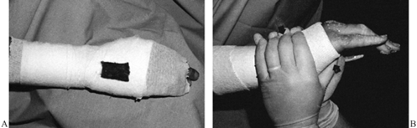
the scaphoid and other instabilities of the carpal bones amenable to
cast treatment. It also is used for fractures involving all elements of
the thumb itself. In scaphoid fractures, most surgeons use a long-arm
thumb spica cast for the initial 6 weeks of immobilization and then
convert to a short-arm spica cast (Fig. 10.62).
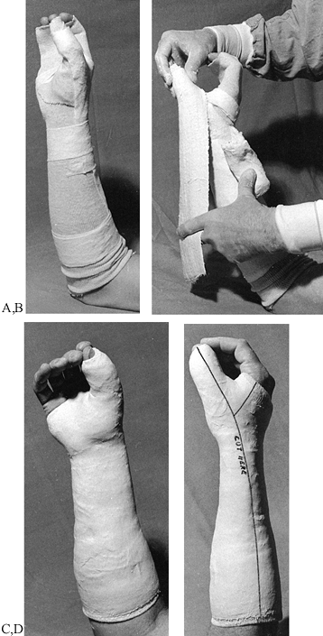 |
|
Figure 10.62. Short-arm thumb spica cast. See text for details.
|
-
Apply a tubular stockinet over the
forearm and hand as done for the forearm cast, and apply a second
tubular stockinet over the thumb. Some custom shaping is necessary to
obtain a snug fit. -
Carry the Webril distal to the end of the
thumb. Apply Webril padding about the palm of the cast and around the
distal phalanx of the thumb. Apply a double-thickness strip of Webril
along the dorsal aspect of the thumb, wrist, and forearm for removing
the cast, and secure it with a circumferential wrap of Webril. -
Position the hand as if holding a soft-drink can to maintain proper position of the thumb relative to the fingers.
-
First apply a roll of plaster to the forearm about four layers thick (Fig. 10.62B).
Then use a 3 × 15-inch splint, five to seven layers thick, and apply it
around the thumb as a splint, as illustrated. This will lap around the
thumb enough that it will not be necessary to actually wrap plaster
circumferentially around the thumb. If a 3-inch roll is not wide
enough, use a 4-inch roll. -
Incorporate this splint and the rest of the hand using the technique already described for a forearm cast.
-
The completed cast is carried well up on the forearm, but not so far that it interferes with the antecubital fossa (Fig. 10.62C).
-
Notice that the thumb is easily opposed
to the first and second fingers. A common mistake with this cast is to
get the thumb out into the ape-hand position, which makes it impossible
for the patient to obtain three-jawed-chuck prehension. The patient
will not be able to function with the cast on. Notice that on the thumb
the cast is carried distally to the middle of the fingernail. This
length provides adequate immobilization yet leaves the tip of the thumb
available for prehension. Making the cast shorter allows the patient to
jack the hand up in the cast by flexing the distal phalanx over the end
of the cast, introducing significant motion into wrist injuries, which
should be avoided. -
The line for univalving the cast and for removal has been indicated by writing on the completed cast (Fig. 10.62D).
This must always be done on casts applied with minimal padding, as in
this case. When the cast is univalved, split the underlying stockinet
as well.
humerus in all areas, including those of the surgical neck. The
principle of the hanging-arm cast is that it relies on traction for
fracture reduction rather than molding of the cast, although molding is
useful in supracondylar fractures. In shaft fractures, the angle of
varus and valgus can be changed by the location of the suspension hook
and the length of the sling that hangs the cast from the neck.
to remain upright most of the time during the first few weeks after the
fracture and must not rest the cast on any surface. Sleeping at night
with the head and upper thorax at a 45° angle usually suffices. Once
the fracture becomes fairly sticky, the cast can be removed and other
methods of immobilization used. The difficulties inherent in using this
cast have limited its use. The best indication today is a fracture of
the surgical neck of the humerus that requires traction for treatment.
-
Apply a standard long-arm cast (Fig. 10.63A).
![]() Figure 10.63. Hanging-arm cast. See text for details.
Figure 10.63. Hanging-arm cast. See text for details. -
Prepare a suspension sling. Determine the
length of sling and location of the suspension point appropriate for
the fracture. Shortening the suspension sling will produce varus;
lengthening will produce valgus. Moving the suspension point toward the
hand will induce more varus, and toward the elbow, valgus. In this
completed hanging-arm cast, a section of coat hanger was used to
produce a loop incorporated into the cast with plaster. -
A loop can also be made by passing a 2-inch roll of plaster around the cast, leaving approximately a handbreadth loop (Fig. 10.63B). Use your finger to twist this loop down to the cast, forming a plaster loop (Fig. 10.63C).
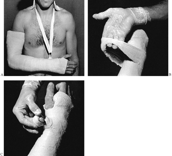
fracture alignment, or wedged progressively on a serial basis to
correct joint contractures. Cast wedging to treat deformity or
contractures requires great care to avoid complications such as
pressure sores and peripheral nerve palsy. Techniques for the
correction of contractures are beyond the scope of this chapter and are
discussed in detail by Bleck et al. (10).
uniplanar or biplanar. If a fracture has angulation in both the
anteroposterior and lateral planes, it is theoretically possible to
place the axis of the hinge in the plane of maximum deformity and
correct both angulations with a single wedge. This technique is tricky
but perhaps worth a try; the alternative, changing the entire cast, may
ultimately be necessary. Another option is to simply remove a 1- to
2-inch segment of cast, align it properly, and reseal the cast. This
technique is more hazardous than wedging, as it is possible to offset
the longitudinal alignment of the cast, producing pressure sores.
closing wedge, and the central-hinging wedge. The opening wedge is most
common, as it is simple and produces distraction. Almost all angulation
in fractures is accompanied by some shortening, so distraction is an
advantage.
-
Make a transverse cut in the cast,
leaving the cast intact for a width of about 1 inch on the convex side
of the deformity. Gently straighten the cast to the desired position. -
Place a wedge in the opening to hold it in position, and take a radiograph to confirm proper position.
-
Seal the cast after removing the wedge.
at the fracture site is desired; indications for it are rare. The
procedure is opposite that of the opening wedge.
-
Remove a wedge of plaster and close the cast on the convex side.
-
Avoid pinching the skin in the closing wedge.
methods that hinges the cast directly over the fracture site and
introduces neither lengthening nor shortening.
-
Place a radiograph of the extremity
alongside the cast and mark the location of the fracture site. This can
also be done by taping a radiopaque object such as a coin or paper clip
to the cast and taking a radiograph. This allows accurate localization
of the fracture. -
To preview what needs to be done, draw the fracture on the cast (Fig. 10.64A). In this case, a mid-shaft transverse fracture of the tibia and fibula has 15° of valgus angulation.
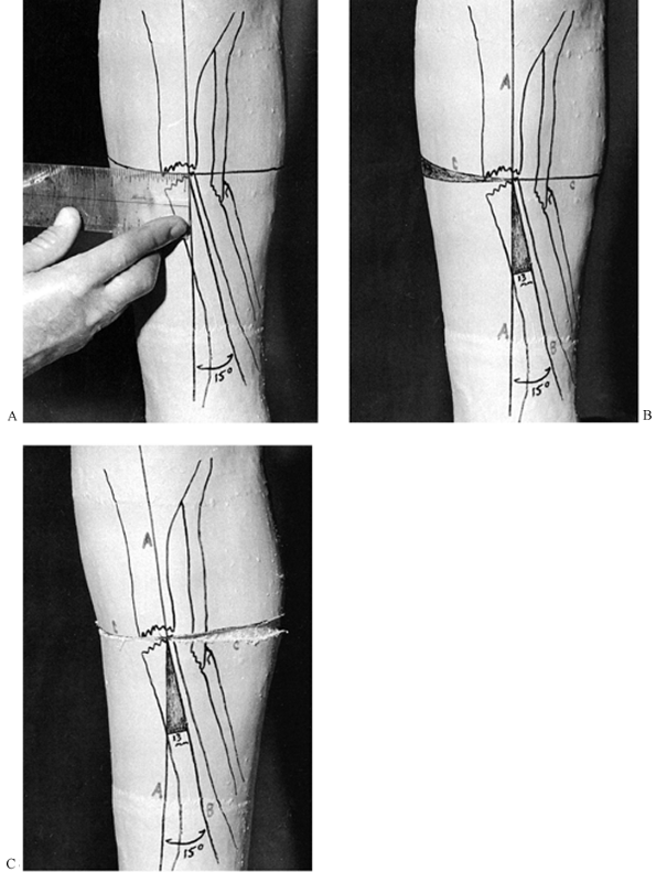 Figure 10.64. Wedging a cast with a central hinge. See text for details.
 -
Draw a line parallel to the proximal
fragment down the length of the anterior aspect of the cast. At the
fracture site, draw a transverse line at right angles to the first
line. Measure the distance from the center of the fracture site to the
edge of the cast (in this case, about 5 cm). -
Draw a line from the fracture site in line with the angulated fragment and mark the angle to be corrected (in this case, 15°).
-
To determine the width of wedge to be taken (Fig. 10.64B),
measure from the fracture site distalward 5 cm, and measure the width
of the base of the wedge produced by this measurement (here, 13 mm).
This is the width of the wedge that will be removed from the cast along
line C, as illustrated. -
From the hinging point, make a single cut along line C on the concave side of the deformity to the exact midline posteriorly (Fig. 10.64C).
-
On the opposite, convex side of the deformity, remove the wedge outlined by your measurements.
-
Now gently close the wedge as illustrated, bringing line B in line with line A.
-
Notice that there are three guides to
whether the appropriate amount of angulation has been corrected: the
alignment of lines A and B, the closure of the wedge along line C, and
the opening of the wedge of the cast on the opposite side of line C. -
Place a cast wedge in the defect produced
in the cast, and temporarily tape the cast in this position. Take an
x-ray to confirm that the appropriate amount of correction has been
made. -
Seal the cast with a single 6-inch roll.
Wrap circumferentially around the cast and then gently mold the plaster
into the defect to completely fill it. Avoid producing a ridge on the
inside of the cast. Complete the coverage of the wedge and thoroughly
rub it in.
the smaller tasks performed by casts, except for the spica casts. The
primary advantages of splints are that they are lighter in weight than
casts, allow for swelling of the limb, and are removable. They are,
however, much weaker, and the fact that they are removable may pose a
problem in noncompliant patients.
first applying a full cast. After drying, bivalve the cast and trim the
edges.
-
On a tabletop, lay out a length of
Webril, three layers thick, that is about 4 inches longer than the
splint desired and somewhat wider than the plaster to be used (Fig. 10.65A).![]() Figure 10.65. Short-leg splint. See text for details.
Figure 10.65. Short-leg splint. See text for details. -
Make a splint of appropriate length and
width, either using commercially available splints or by unrolling a
roll of plaster. For most lower extremities, a splint 10 layers thick
with reinforcement to 15 layers around the foot and ankle is usually
sufficient. -
Take the 10 to 15 layers of plaster
splints as a unit, fold them in half without creasing the plaster at
the fold, and grasp the two ends between the fingers of one hand. -
Dip the splints into water and let them
soak thoroughly. Since little molding time is required for splints and
fast setting is an advantage, use warmer water or extra fast setting
plaster. -
Remove the splints from the water, bunch
them into a ball while maintaining good control of the ends of the
splints, and express excess water from the splints. -
Then unfold the splint out to full length and strip the splint between two fingers, as illustrated, to remove excess water.
-
Lay the splint on the prepared Webril and thoroughly rub the splint in to ensure that all the layers are amalgamated (Fig. 10.65B).
-
Place over it a layer of Webril similar to the one used for the bottom of the splint.
-
Apply the splint to the leg, holding the foot in the appropriate position (Fig. 10.65C).
-
Now wrap the splint into place with bias-cut stockinet, maintaining good position until the splint hardens (Fig. 10.65D). If not wrapped too tightly, elastic bandages can be used as well.
-
Figure 10.65E shows the completed short-leg splint. Notice that the Webril has been turned down over the edges for trimming and padding.
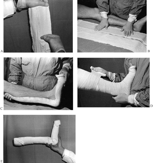
-
A snug-fitting long-leg posterior splint
applied by multilayering produces a very strong and smoothly conformed
splint with a thin, smooth edge (Fig. 10.66A).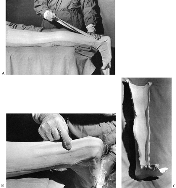 Figure 10.66. Long-leg splint using multilayered technique and reinforcing ridge. See text for details.
 -
Position the extremity in the desired position.
-
Pad as desired. In this case, the splint
is being applied directly to tubular stockinet. Padding or protection
should be placed over the heel, malleoli, and fibular head. -
Take thin splints (only two or three
layers thick) and apply them in a series of sequential layers,
thoroughly rubbing in the plaster with each layer. -
A trick for reinforcing the cast at weak
points such as the heel is to draw up the last splint with the fingers
into a reinforcing ridge (Fig. 10.66B). -
Once set, the splint can be removed and is ready for trimming (Fig. 10.66C).
device for the management of fractures of the shaft of the humerus.
Critical to its success is three-point molding. I have not found it
useful to carry the splint any higher than the tuberosities of the
humerus. Avoid pressure over the ulnar nerve.
-
Loop a single long splint padded with Webril on both sides around the elbow and along the medial and lateral sides of the arm (Fig. 10.67A).
![]() Figure 10.67. Sugar-tong splint for fractures of the shaft of the humerus. See text for details.
Figure 10.67. Sugar-tong splint for fractures of the shaft of the humerus. See text for details. -
Overwrap it with bias-cut stockinet,
keeping the splint snug around the elbow. Do not impinge on the axilla.
Carry the splint up to the greater tuberosity of the humerus. -
Molding into valgus is necessary for most
supracondylar fractures. The torso is used as the molding point over
the lateral aspect of the elbow (Fig. 10.67B).
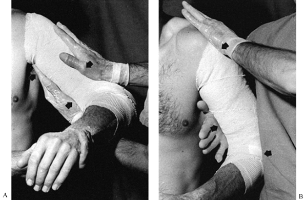
necessary to immobilize the elbow and forearm or if a circumferential
cast is undesirable, as in supracondylar fractures of the humerus. With
the long-arm splint shown in Figure 10.68,
the antecubital fossa is left completely open to check the pulse and allow for swelling.
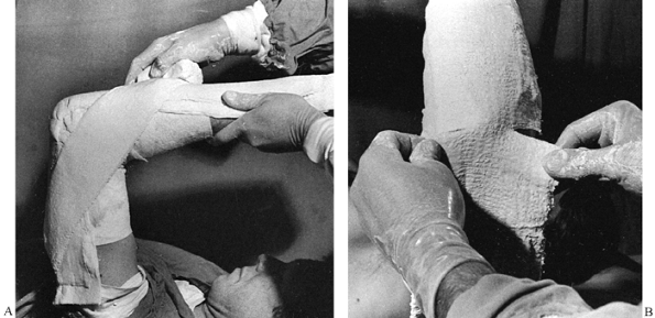 |
|
Figure 10.68. Long-arm splint. See text for details.
|
-
Apply this splint to the dorsal side of the arm and forearm, extending to the base of the metacarpal heads (Fig. 10.68A).
These splints often break at the elbow. An excellent method of
reinforcement is to apply a splint at a 45° angle along the medial and
lateral sides of the elbow, although this leaves the antecubital fossa
and volar side of the arm and forearm completely open. The splint can
be applied with a roll of plaster, as illustrated. -
The splint is wrinkled on the lateral side of the elbow from having been molded around the elbow joint (Fig. 10.68B).
This wrinkling can sometimes produce irregularities in the cast that
are uncomfortable or that can impinge on the ulnar nerve. -
To produce a smooth fit of splints around
joints, cut the splint as illustrated and allow it to overlap. The
overlap also reinforces the splint on its two sides.
casts because splints easily accommodate swelling, are lightweight, and
in some cases are easier to mold than a circumferential plaster. In
addition, they can be tightened by overwrapping as swelling decreases.
-
Precut the splints to conform to the palm of the hand and to fit around the thumb (Fig. 10.69A).
![]() Figure 10.69. Short-arm splint for Colles’ fracture. See text for details.
Figure 10.69. Short-arm splint for Colles’ fracture. See text for details. -
Produce a snug-fitting splint by reducing the fracture in fingertraps and padding with tubular stockinet and some Webril (Fig. 10.69B).
-
Apply the volar and dorsal splints in the multilayered technique (Fig. 10.67). Overwrap the splints directly with a roll of gauze. This gauze will stick to the plaster.
-
Apply these splints rapidly so there will be plenty of time for molding.
-
After the splint sets, cut the gauze
along either the ulnar or the radial border, depending on the fracture
being treated. Then overwrap with a gauze or other wrap to obtain the
desired fit (Fig. 10.69C).
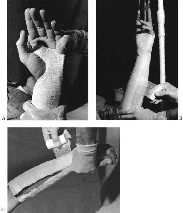
some of which are quite complicated. Hand splints are often combined
with wire splints, padded aluminum splints, and outriggers with elastic
bands. Splints of metal or polymers are commercially available and are
often custom-fabricated by occupational or hand therapists.
of acute hand injuries. Splints are often used to treat nerve injuries,
paralysis, and burns and are otherwise used to position the disabled
hand. The use of splints for the treatment of traumatic and
nontraumatic disorders of the hand and wrist is discussed in some
detail throughout the many chapters in the section on the hand. Please
refer to a chapter on a specific disorder to find recommendations on
splinting, if applicable.
method for immobilizing nearly all soft-tissue and bony injuries of the
thumb, metacarpal, phalanges, and associated joints. It can be used as
a temporary splint for the wrist and carpal bones. It is very useful as
the first stage of a thumb spica cast, as it minimizes the need to wrap
rolls of plaster around the thumb. Once hardened, it can be removed for
exercise or examination of the limb and replaced.
-
Use seven to ten layers of 3 × 15-inch plaster splints overlaid on both sides with Webril to construct the splint (Fig. 10.70A).
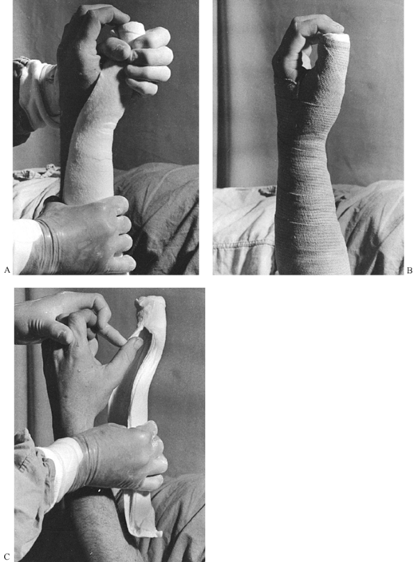 Figure 10.70. Thumb spica splint. See text for details.
 -
Turn the Webril over the edges of the splint to give it a smooth edge.
-
Apply the splint along the radial aspect
of the forearm, extending onto the thumb as far distally as the middle
of the thumbnail. The splint should fit circumferentially around the
thumb. The splint width will vary according to the size of the patient. -
Molding around the thumb with the thumb in a position of three-jawed-chuck prehension is usually preferred.
-
The completed splint (Fig. 10.70B)
has been overwrapped with an elastic bandage; this is ideal for molding
it to the arm while it sets. If there is any concern about having an
elastic wrap on the extremity, replace it with bias-cut stockinet or
other nonelastic wrap after the splint has set. -
Notice how nicely this splint can be removed from the thumb (Fig. 10.70C),
leaving the circumferential thumb portion intact. It can be slid back
onto the thumb and gently pushed proximally to obtain a snug fit, and
rewrapped into place.
that of the thumb spica splint. If extended out to the tip of the
digit, it can serve to immobilize injuries of the ulnar fingers and
ulnar metacarpals, or it can immobilize the wrist with the fingers
free, depending on its distal extent. Splints that are 3 × 15 inches
will just cover the fifth finger in medium-size adults and children;
wider splints are necessary to incorporate the ring finger. A very wide
splint, such as a 6-inch splint, can be used to incorporate the entire
hand. It is my favorite splint for immobilizing boxer fractures of the
neck of the fifth metacarpal (Fig. 10.71).
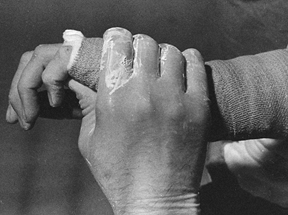 |
|
Figure 10.71. Ulnar gutter splint.
|
-
Use a 3 × 15-inch splint as described for the thumb spica splint. For large hands, a 4 × 15-inch splint may be necessary.
-
Carry the splint to the midportion of the middle phalanx of the little finger, allowing the more distal joints free to flex.
-
Use three-point molding to reduce the
fracture in place, with one point over the palmar aspect of the head of
the fifth metatarsal and a broader area of molding over the dorsal
shaft of the metacarpal. Rotation is usually not a problem in these
fractures. -
If there is more proximal shaft comminution, then buddy-tape the little finger to the ring finger.
-
In more unstable injuries, outrigger splints may be indicated, which can be incorporated into the ulnar gutter splint.
-
Take care when molding this splint to avoid excessive pressure, as pain or skin injury could occur. Placing a 1/8-inch piece of felt over the molding points is helpful in distributing pressure.
-
Splint only the joints that must be splinted; allow free movement of the other joints to prevent stiffness in the hand.
-
The primary problems in the
immobilization of major fractures of the fingers are malrotation,
dorsal angulation at the fracture site in metacarpal fractures, and
palmar angulation in fractures of the phalanges. These problems are
usually avoidable by proper splinting, but severe instability,
recurrent deformity, or the presence of other soft-tissue injuries may
necessitate internal or external fixation. -
When splinting fingers, check carefully
for proper rotation. As each digit is fully flexed to the distal palm,
it reaches a specific contact point on the thenar eminence; these
points differ from person to person (Fig. 10.72).
Good rotation can usually be ensured by taping the injured digit to an
adjacent noninjured digit. The index and little fingers have only one
neighboring finger to be taped to. Tape the long finger to the ring
finger, leaving the index free for function. Tape the ring to the long
finger, because the long finger gives the proper rotation more reliably
than the little finger (in some patients, the little finger is
internally rotated and would splint the ring finger in malrotation).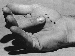 Figure 10.72.
Notice the contact points produced by contact of each of the fingers
with the thenar eminence. This rotational alignment must be reproduced
when unstable fractures in the fingers are immobilized.
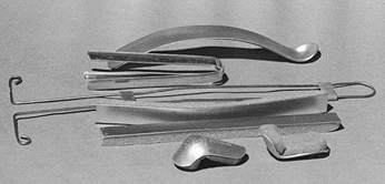 |
|
Figure 10.73. Splints for the fingers. From top to bottom,
an aluminum gutter splint for the finger designed to be used on the palmar side, a straight four-sided aluminum finger splint (generally not recommended because it splints the digit in full extension), a wire finger splint; strips of aluminum with adherent foam, and foam-padded mallet-finger splints. |
free or by allowing limited motion of the digit while splinting it to
prevent recurrence of deformity or dislocation. For example, a dorsal
finger splint can be incorporated into a short-arm cast or volar wrist
splint to immobilize injuries that are stable in flexion but unstable
in extension. The splint in Figure 10.74 blocks extension of the finger but allows nearly full flexion.
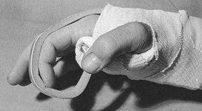 |
|
Figure 10.74. Finger splint allows limited motion.
|
-
Fashion a 3 × 5-inch Webril-padded plaster splint of about 10 thicknesses for the wrist.
-
Incorporate the foam-padded aluminum splint into the splint on the palmar side and into a second splint on the dorsal side.
-
To achieve good incorporation and to
reduce bulk, peel the foam from the portions of the splint inserted
into the plaster. Notice that the splint has been bent to maintain the
index finger in flexion, thus stabilizing an injury that is unstable in
extension.
excellent flexion for early motion. A similar splint could be used if
the index and long fingers were taped together.
complete immobilization except for the distal interphalangeal joint may
be necessary. For splinting the index and/or long fingers, a
foam-padded aluminum splint can be bent into a complete loop and
incorporated into a palmar wrist splint (Fig. 10.75).
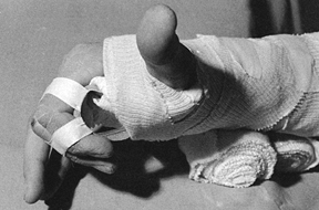 |
|
Figure 10.75. Padded aluminum splint of the index finger incorporated into a wrist splint.
|
-
Splint the metacarpophalangeal joint as
close to 90° of flexion as feasible. Note that the proximal
interphalangeal joint has also been immobilized at 90°. -
Bend the splint into a full loop with
your hand. Bend the splint down until the loop is sufficiently tight
that you can bring your fingers into the appropriate position. -
Strip the foam off the aluminum where the
splint will be incorporated into the cast. Tape the ends of the splint
together. This produces a nice, stable loop on which the finger will be
set. -
Position the volar wrist splint no more
distal than the proximal flexion crease of the palm, as this position
is necessary to achieve the desired flexion of the fingers. The splint
illustrated here is slightly too distal. -
Leave the fingertips free. Encourage early motion to avoid flexor tendon tie-down and stiffness.
-
To avoid maceration between the fingers,
place Webril or gauze between the digits. The tape fastening the
fingers to the splint must be snug but not tight.
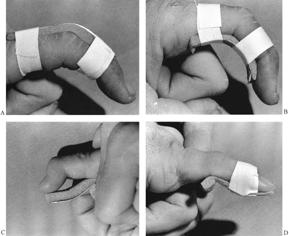 |
|
Figure 10.76. Use of padded aluminum splints for finger injuries. See text for details.
|
-
Cut the splint to size with a large bandage scissors.
-
Smooth the cut edges of the splint. Allow the foam to extend somewhat beyond the ends of the splint to protect the finger.
-
Figure 10.76B shows the splint on the palmar aspect of the finger.
-
To splint a mallet finger (Fig. 10.76C), fashion a splint to reach from the tip of the finger to the middle of the middle phalanx.
-
Smooth the ends of the splint and leave
plenty of foam over the edge of the splint to pad its edge. Notice the
bend in the splint that will place the digit in slight hyperextension
at the distal interphalangeal joint. -
Apply the splint to the palmar aspect of the digit and tape it into position over the distal interphalangeal joint (Fig. 10.76D).
Sometimes this procedure is painful because of the injury, and a more
indirect means of taping must be used. Usually the tape must be applied
somewhat loosely initially and then gradually tightened over a couple
of days as the tenderness and swelling subside. Because these splints
get wet, the patient must replace them frequently, taking care not to
allow the joint to drift into flexion. Off-the-shelf plastic splints
are available for this application, but I prefer to use custom-molded
splints. Generally, immobilization of the proximal
P.282
interphalangeal joint is unnecessary in a mallet finger.
the edges of the cast, or over flexion surfaces such as the instep and
antecubital fossa. With good plaster technique, pressure sores should
be extremely rare in patients with normal sensation. They are most
common in patients with sensory loss such as paraplegics, and in those
with peripheral nerve disorders, including peripheral neuropathy from
diabetes and other disorders. Head-injured patients who cannot
communicate, small children, and the very elderly are also at risk. Try
to avoid circumferential casts in these patients, particularly in
paraplegics. On the other hand, short-leg antiequinus casts are often
used to prevent heel-cord contractures in head-injured patients who are
comatose and spastic. I have been very successful in avoiding pressure
sores by appropriate padding and careful cast application.
source of pressure. Note that the cast is very thin over the olecranon
and very thick over the antecubital fossa because of inappropriate cast
application. Avoid excessive plaster over the flexor surface of joints.
In addition, in this case the forearm portion of the cast was too long,
so when the forearm was flexed at the elbow to 90°, the forearm part of
the cast impinged on the antecubital fossa, producing a potential site
for pressure necrosis of skin. Solve this problem by removing the
antecubital part of the cast with a window, and reapply the plaster in
this area; it may be easier to apply a new cast.
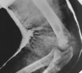 |
|
Figure 10.77.
Cast sores. Notice the inappropriate application of this long-arm cast with impingement of the forearm portion of the cast into the antecubital fossa, which could well cause a pressure sore or neurovascular injury. |
The patient with an impending cast sore initially complains of
discomfort in the cast, usually in a region where pressure would be
expected, such as over the heel, instep, patella, olecranon, or
antecubital fossa. This discomfort quickly becomes an unrelenting,
severe, burning pain. It may last for several hours up to several days,
depending on the severity of the pressure and whether or not the
patient can gain temporary relief by shifting in the cast or
repositioning. Eventually, the pain usually subsides in part and the
patient becomes more comfortable; at this point a full-thickness
ulceration has usually occurred. Subsequently, staining on the cast, a
foul smell, or systemic evidence of infection will call attention to
this neglected problem.
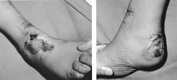 |
|
Figure 10.78.
These pressure sores over the instep and heel of the foot were caused by a long-leg cast applied to a patient with a fracture of the proximal tibia who was multiply injured and unconscious for 3 days. Although the initial cast was probably applied in an appropriate manner, subsequent swelling in the cast, about which the patient could not complain, led to these pressure ulcers. These full-thickness ulcers resulted in exposure of the Achilles tendon and calcaneus, and full exposure of the extensor tendons of the ankle; major plastic reconstructive surgery was required. These problems could have been avoided by univalving the cast and spreading it widely initially, or by using splints with frequent inspection of the skin. |
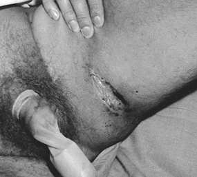 |
|
Figure 10.79.
This pressure sore in the groin occurred at the upper edge of a cast-brace used to treat a lower extremity injury in a paraplegic. Even though the cast was well applied and appropriately padded, it was inadequate in this patient with impaired sensation. |
loss of coverage over bony prominences or full exposure and loss of
tendons, ligaments, and nerves. They can require major reconstructive
surgery and result in permanent, major, long-term deficits. Avoid
pressure sores by observing indications, by using appropriate
technique, and by using immediate decompression of circumferential
casts or snugly applied splints in patients complaining of pain or
discomfort. In almost all cases, keep the offending area visible by
placing a large window in the cast, by splitting the cast and spreading
it, by bivalving the cast, or by removing the cast completely.
plaster and fiberglass materials, enough heat can be generated to cause
a severe burn, particularly if there is no way for the heat to
dissipate. This is a greater problem in patients with impaired
sensation. To avoid burns, try not to apply casts thicker than ¼ to 3/8
inch in a single layer. For a thicker cast, it is wiser to apply a thin
cast initially, reinforcing it after it has set. This is commonly done
by overlaying plaster casts with a thin layer of fiberglass.
unwary. Fresh casts are often laid on pillows as they set. Burns can
occur because the setting plaster can not dissipate heat while lying
against the plastic. Avoid setting
fresh casts down on any impervious surface, and do not cover freshly set casts.
exceedingly rare. Skin irritation under the cast is most likely to be
caused by exudate from wounds soaking the cast padding, or from
particles of plaster dust getting into the cast and abrading the skin.
I do not believe I have ever seen a true allergy to either the padding
materials or to plaster of Paris, although it has been reported. An
occasional reaction to the tubular stockinet occurs; in patients with a
history of allergy or dermatitis, do not use tubular stockinet directly
against the skin. Synthetic materials are more likely to cause
allergies, so be alert to this possibility. Change materials if allergy
is a problem.
is exposed while most of the limb is incorporated in the cast. Any
swelling that occurs will bulge into the window or split and may create
excessive pressure against the skin along the edges of the split or
window. The result is a pressure sore or more commonly a blister in the
window
or
split. Fill any windows or splits with soft compressible material, such
as felt or multiple layers of Webril or dressings, and overwrap with
bias-cut stockinet or plaster to keep firm compression.
splints rarely occurs; the vessels are buried deeply enough that direct
compression is almost never a problem. Excessive swelling, however, can
cause compartment syndrome; avoid it by using splints. In any type of
acute injury, or if there is any possibility of swelling, I always
split longitudinally and univalve circumferential casts. Bivalving
casts does not decompress the limb nearly as well as spreading a cast
that has been univalved, as the bivalved cast can open only in one
plane. See Chapter 27 on compartment syndrome for more details.
at the elbow, the radial nerve at the lateral epicondyle, and the
median nerve at the wrist. In the lower extremity, the most common and
serious problem is paralysis of the foot and toe dorsiflexors due to
paralysis involving the common peroneal nerve at the fibular neck. This
paralysis may produce a permanent drop foot and must be avoided. Any
neurologic complaints—pain, burning, dysesthesia, weakness, or
paresthesias—demand immediate attention. Window, remove, or adjust the
cast or splint. In some cases, such as carpal tunnel syndrome at the
wrist, repositioning to decrease intracompartmental pressure may be
necessary.
the positioning of joints. The measures necessary to mold fractures
appropriately to maintain position have been described. When treating
fracture–dislocations and dislocations, remember the positions of
stability for the joint, and position the extremity appropriately. Keep
in mind that very unstable injuries of the elbow and knee may not be
adequately immobilized by a long-arm or long-leg cast and may require
extension into spica casts. Joints may be stable in a slightly flexed
position but completely unstable in extension. Position may be so
critical that when splints and casts are applied by technical personnel
to potentially unstable injuries, physician supervision is usually
necessary to ensure that appropriate position is maintained.
application may result in annoying problems, if not prolonged
disability. When applying a long-leg cast, for example, do not hold the
extremity by the heel with the patient in the supine position, as
gravity will cause the knee to drop into hyperextension, which is very
uncomfortable for the patient. Other common positions to avoid are toe
hyperextension, excessive flexion of the knee when it is unnecessary,
excessive flexion of the hip, or any varus or equinus of the foot when
not indicated.
important to immediately embark on a rehabilitation program. All joints
not immobilized should be carried through active range-of-motion
exercises daily, and passive exercise is generally indicated for joints
or digits that cannot be moved actively. Generally, it is safe to begin
immediate isometric exercises of the immobilized muscles.
use of the extremity when feasible. Avoid slings when possible. In
Colles’ fractures, for example, use of a sling may produce a stiff
shoulder due to disuse. To avoid swelling in the first few days, the
patient is better encouraged to carry the extremity resting on the head
and thereafter to use it as much as possible as if it were normal.
soon as possible and should be actively encouraged when indicated. In
general, tibial fractures should be treated with weight-bearing
functional plaster casts and braces rather than non-weight-bearing,
long-leg, bent-knee casts. Convert from casts to functional braces as
soon as practical and safe. Early involvement of a physical therapist
or hand therapist is often indicated.
complications. Every orthopaedic office, clinic, and emergency room
should have a standard handout to educate patients about the care of
casts and splints and to warn about the symptoms that must be brought
to the physician’s attention.
fractures when reduction of the fracture or proper length of the limb
cannot be maintained by the static immobilization provided by casts and
splints. It is necessary in the presence of deforming forces caused by
soft-tissue tension in the muscles, tendons, and ligaments, and by
hydraulic forces generated by bleeding into and swelling in the
soft-tissue envelope surrounding the fracture. Traction may also be
necessary to treat unstable dislocations, particularly of the hip,
where static methods are inadequate or impractical. Because of the
sophistication of modern methods of internal and external fixation, it
is uncommon to treat fractures or dislocations definitively in
traction. Disadvantages include the need for prolonged bed rest and
prolonged
and expensive hospitalization. Additionally, the return to function is
slow; the patient is recumbent in traction for so long that muscle
atrophy, joint stiffness, and general cardiovascular deconditioning
result.
problems, as current methods of internal and external fixation are
usually superior. At the University of California, Davis, Medical
Center, a busy level 1 trauma center with more than 3,000 trauma
admissions per year, I have not used traction since the 1980s for even
the temporary treatment of a disorder in the upper extremities, but
olecranon pin traction is described below because it is a very useful
method that I used frequently in the 1960s and early 1970s.
of traction, as it is a good backup method for situations where
internal and external fixation are impossible. In particular, it may be
useful in the management of major soft-tissue injuries in the upper
extremity because the overhead suspension provides ready access for
wound care. With the advent of percutaneous pin fixation for
supracondylar fractures of the humerus in children, traction treatment
has virtually disappeared and in most Western countries is not
indicated.
however. Common indications are Malgaigne injuries of the pelvis with
vertical instability, fractures of the hip and shaft of the femur, and
fractures of the tibia and fibula. Unstable posterior dislocations of
the hip are often immobilized in skeletal traction until soft-tissue
healing occurs. Skin traction is commonly used to immobilize elderly
patients with fractures of the hip as an emergency measure before
performing internal fixation. Skeletal traction through either the
distal femur or the proximal tibia is used for the temporary and early
treatment of unstable fractures of the pelvic ring and acetabulum, the
hip in younger patients, and femoral shaft and supracondylar fractures
of the femur. Where traction is used for vertically unstable fractures
of the pelvic ring, fixation is often supplemented by an external
fixator on the pelvic ring.
or external fixation is the definitive method of treatment; however,
local soft-tissue and systemic conditions may contraindicate surgery
and necessitate prolonged definitive treatment in traction. Since
external fixator and intramedullary nailing have not been tested in the
face of the major mass casualties produced by war, skeletal traction
remains the only proven treatment for high-velocity gunshot wounds of
the femur in a military situation. It is highly likely that external
fixation is a better treatment method, but its efficacy in this
specialized situation has not been proven.
-
Vertically unstable fractures of the
pelvic ring where external fixation cannot maintain vertical stability,
and where internal fixation of the posterior portions of the pelvic
ring is impossible -
Fractures of the acetabulum with minimal
displacement where internal fixation is not indicated, the fracture is
potentially unstable, and the patient is a good candidate for treatment
in traction (i.e., young, with isolated injuries) -
Unstable fractures of the acetabulum
where either local bone or soft-tissue conditions or systemic factors
contraindicate internal fixation -
Fractures of the hip (basilar neck,
intertrochanteric, or subtrochanteric) where local soft-tissue or bone
conditions or systemic conditions contraindicate surgery -
Fractures of the shaft and supracondylar area of the femur for which internal or external fixation is contraindicated
-
Comminuted fractures of the tibial
plateaus where traction is necessary to maintain alignment and
facilitate early motion, and where internal or external fixation is not
possible or feasible. (Sometimes, traction may be supplemented with
closed reduction, or limited open reduction of the articular surfaces
with percutaneous fixation with wires or cannulated screws, with the
metaphyseal portion being managed in traction.) -
Fractures of the shaft of the tibia and
fibula where delay in initial treatment or unacceptable shortening in a
plaster cast requires correction. (In such cases, it is desirable to
regain length before internal or external fixation, or where severe
soft-tissue problems preclude cast immobilization or any type of
fixation.) -
Comminuted pylon fractures of the distal
tibia and fibula and ankle joint, where early motion of the ankle joint
is desired and internal or external fixation is contraindicated
In it he states that Malgaigne credited Guy de Chauliac with the first
use of continuous isotonic traction for the treatment of fractures of
the femur; this was 600 years ago, and traction remains today an
effective and safe treatment for fractures (49).
Initial efforts at traction treatment were frustrated by the surgeons’
inability to obtain a firm grasp on the extremity to apply traction.
Skin traction had obvious limitations. In addition, skin traction meant
that the limb had to be treated in full extension, resulting in
frequent shortening and malalignment.
longitudinal traction for femur fractures was introduced by Sir Hugh
Owen Thomas in 1890 (93). The full-ring Thomas splint used today is identical to the one Thomas developed.
His original method used skin traction and treated the fracture in full extension (Fig. 10.80).
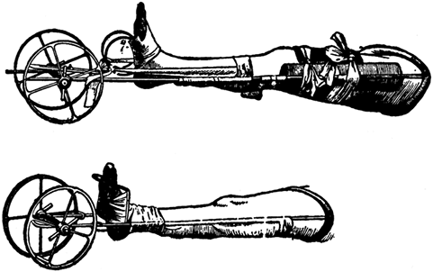 |
|
Figure 10.80.
This long splint, designed by Sir Hugh Owen Thomas for the treatment of fractures of the shaft of the femur, was described by him in 1890. Note the use of skin traction and treatment of the fracture in full extension. The wheels at the end of the splint were used to facilitate traction. The full-ring Thomas splint itself remains unchanged today. (From Peltier LF. A Brief History of Traction. J Bone Joint Surg Am 1968;50:1603.) |
hip and knee to reduce the tension in the muscles and soft tissues that
caused deforming forces on the fragments of the femoral shaft. Most
surgeons endorsed his ideas, and traction treatment was modified
thereafter to incorporate flexion of the joints above and below the
injury (70). Pott used his method with the limb lying on its side, a position that was hardly practical. Mayor (51) and Sauter (85)
developed the concept of balanced suspension of splints, which enabled
the limb to be suspended in a flexed position. Suspension and traction
in combination were first introduced by Nathan Smith prior to the
American Civil War and published in 1867 (Fig. 10.81) (88,89 and 90).
During the Civil War, Hodgen further refined Smith’s splint and
provided a mechanism for providing both suspension and traction through
the splint (39). The Hodgen splint saw considerable use during World War I (64).
Hodgen splints were still available at San Francisco General Hospital
when I did my residency there in the early 1960s; they were used in
combination with skeletal traction (Fig. 10.82).
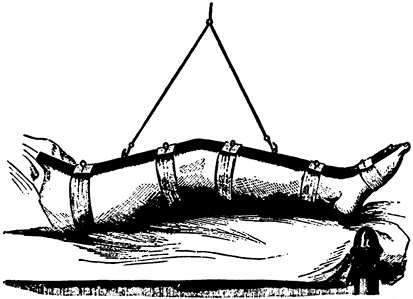 |
|
Figure 10.81.
Nathan Smith introduced suspension in the treatment of fractures of the femur with this suspended traction splint. No effort was made to incorporate traction. (From Peltier LF. A Brief History of Traction. J Bone Joint Surg Am 1968;50:1603.) |
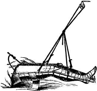 |
|
Figure 10.82.
Hodgen, in 1865, modified Thomas’s splint, incorporated Smith’s suspension, and produced an apparatus that could be used for both traction and suspension. (From Peltier LF. A Brief History of Traction. J Bone Joint Surg Am 1968;50:1603.) |
through the splint itself. The concept of applying adhesive plaster
directly to the skin of the leg for traction was introduced somewhat
before the Civil War and is used today with only slight modifications.
Although Crosby initially proved its effectiveness, Gurdon Buck’s 1861
publication describing his experience using skin traction for the
treatment of 21 patients with fractures
of the shaft of the femur led to the method being known as Buck’s traction (Fig. 10.83) (16). A modification of Buck’s original method is still the standard method of applying skin traction today.
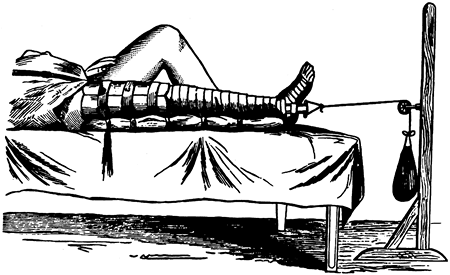 |
|
Figure 10.83.
Buck, in 1883, improved the ability to apply traction to the skin by his method of isotonic skin traction with treatment of the fracture in extension. (From Peltier LF. A Brief History of Traction. J Bone Joint Surg Am 1968;50:1603.) |
adapt Buck’s method to the treatment of fractures of the shaft of the
femur in young children (Fig. 10.84) (15).
Although much care is required to avoid complications from the
traction, Bryant’s traction remains a useful method for treating
subtrochanteric fractures of the femur in infants and young children.
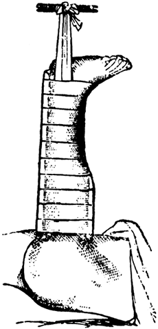 |
|
Figure 10.84.
Bryant, in 1879, modified Buck’s method for the treatment of fractures of the femur in children. This method is still occasionally used today for infants and small children with subtrochanteric fractures of the femur when initial traction at 90° of flexion of the hip is necessary to obtain a satisfactory reduction. Most young children’s femur fractures are treated today with closed reduction and immediate spica cast. Care must be taken in the application of the skin traction to avoid skin problems and decubitus ulcers about the knee and ankle. Although Bryant’s original illustration shows only one leg in traction, most surgeons put both legs in traction. This method is suitable for small children under 2 years of age. It should not be used in children older than 2 years of age because of the risk of ischemia and compartment syndrome caused by the overhead position of the extremities. Enough weight is applied to lift the buttocks slightly off the bed. Subtrochanteric fractures in this age group quickly become stable; therefore, Bryant’s traction is rarely used for more than 3 weeks. (From Peltier LF. A Brief History of Traction. J Bone Joint Surg Am 1968;50:1603.) |
treatment with skin traction by combining Buck’s traction method with a
sling system that allowed the limb to be treated in flexion (Fig. 10.85) (83). Russell described his method in 1921 and it is still used today when skeletal traction is not required.
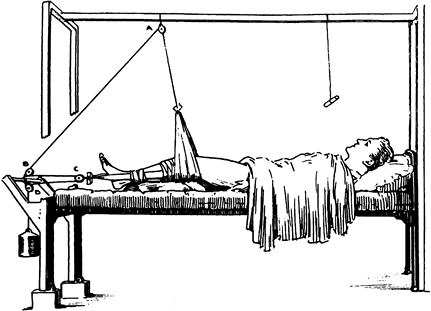 |
|
Figure 10.85.
In 1924, Russell introduced his flexion method for the treatment of fractures of the shaft and the femur, which used skin traction; see Fig. 10.90. (From Peltier LF. A Brief History of Traction. J Bone Joint Surg Am 1968;50:1603.) |
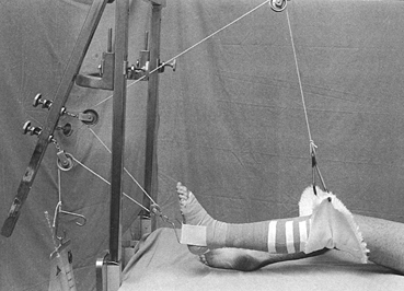 |
|
Figure 10.90.
Although it is almost never used today, this is an illustration of Russell’s traction as used with modern traction materials. Skin traction is applied as demonstrated in the previous figure. |
realized that malunions of fractures of the femoral shaft were quite
common when treated with these methods. Although methods of skeletal
fixation and traction had been described several years before, Pearson
in 1919 introduced the first popular method of skeletal traction, using
a type of ice tong to grasp the distal femur (69). At the same time, he popularized an attachment to the Thomas splint that allowed the knee and hip to be flexed (Fig. 10.86). Tongs did not provide secure attachment to bone, and skin problems were common.
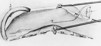 |
|
Figure 10.86.
Pearson, in 1919, introduced the successful use of skeletal traction on the femur. He combined this with attachment to the Thomas splint, which allowed the knee to be flexed, improving the reduction of fractures of the femur and making the traction practical. (From Peltier LF. A Brief History of Traction. J Bone Joint Surg Am 1968;50:1603.) |
Both of these methods are used today, little changed from the original
introduced nearly a century ago. Lorenz Böhler, the well-known surgeon
from Vienna, modified and improved these methods and popularized them
throughout the world (11).
manufacturing methods to refine these basic techniques, but they remain
much the same. The principles established by our ancestors centuries
ago remain valid.
slip, must be easy to tie, and most important must be easy to untie for
adjustment of traction. Three basic knots are very useful and should be
known by all who use traction: the square knot, bowline, and clove
hitch. Frayed rope ends are unsightly and can be unsafe if the
unraveling of the rope gets caught in the traction apparatus or causes
failure of a knot. Wrap the rope end circumferentially with tape and
then cut across the tape to produce a neatly trimmed end.
is the most common and useful knot for tying a rope to itself or to
other objects. Note the direction of the strands of the rope in this
illustration. At either end of the knot, the free strands must pass on
the same side of the loop to avoid a granny knot. Take care: If the two
overhand knots are not laid flat, a series of slip knots can be
produced, and they will slip.
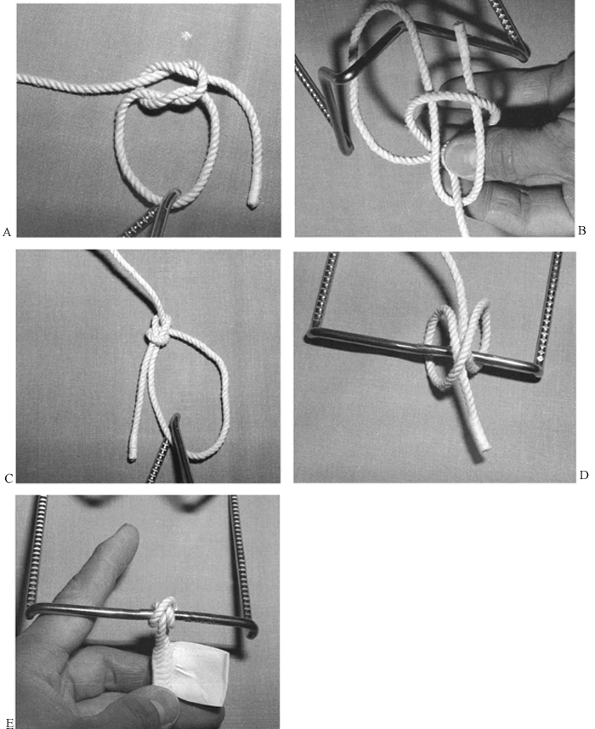 |
|
Figure 10.87. Knots for traction. See text for details.
|
is used to attach the rope to itself around an object, or to join two
ropes. Make a loop in the rope. In the illustration, the loop is being
held by the left hand. Notice that the vertical portion of the rope
(“the tree”) comes from beneath the horizontal component of the loop
(“the ground with a hole in it”). The direction of the free end of the
rope is easy to remember using this mnemonic. The upright strand
represents a tree with its roots under ground, and the loop is a hole
in the ground adjacent to it. Think of the end of the rope as a rabbit.
The rabbit jumps out of its hole, runs around the tree, and dives back
into its hole. Grasp the two free ends and pull the knot snugly
together.
a common knot used in sailing and horseback riding, is used to attach
the rope to a fixed object such as a post or a splint. It is two
half-hitches reversed on each other and tied around the splint. In the
completed clove hitch (Fig. 10.87E), tape the
free end of the line to the rope to ensure that the clove hitch will
not unwrap. Notice that the end of the tape is folded back on itself
and left free so that the knot can be easily adjusted. This versatile
knot can be loosened and slid along the splint and retightened to
adjust the line of pull.
same for the upper and lower extremities. Avoid pressure over bony
prominences and superficial nerves and vessels. The material used to
apply the traction should be adhered to the limb over as wide an area
as possible to avoid concentrated areas of traction and shear lines
where blisters might occur. Commercial off-the-shelf devices for skin
traction for the lower extremity use a soft foam liner and Velcro
straps; often, a support for the foot is included. These are quite
useful and work well for temporary traction in patients who will be
going to surgery shortly for stabilization of femur fractures.
Generally, longitudinal pull of more than 5 pounds is impractical with
these devices. For stronger traction and for prolonged traction, I
recommend application of skin traction using one of the two following
methods.
-
Wrap four layers of Webril around the foot and ankle to protect the bony prominences and neurovascular structures.
-
Next, wrap a 4-inch elastic bandage gently around the foot and ankle (Fig. 10.88A).
![]() Figure 10.88. Buck’s skin traction. See text for details.
Figure 10.88. Buck’s skin traction. See text for details. -
Apply a traction strip and then incorporate it with the elastic wrap.
-
Incorporate the traction strip with the elastic bandages to just below the common peroneal nerve (Fig. 10.88B).
-
Double the traction strip back on the leg and complete incorporation with the elastic bandage.
-
Place the traction loop or block through
the traction strip at the bottom of the foot and apply the traction
rope. The traction loop or block is important to prevent
P.290P.291
traction
from causing excessive pressure over the malleoli. This simple method
allows application of traction for up to 5 pounds for short periods of
time. If the traction is used for more than 24–36 hours, it should be
unwrapped daily for skin inspection and then replaced.
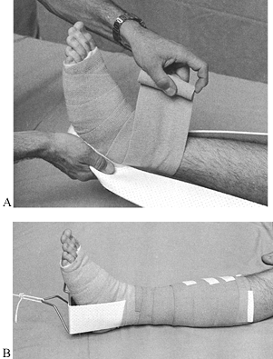
-
Apply Webril around the foot and ankle to protect neurovascular structures and bony prominences (Fig. 10.89A).
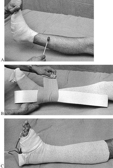 Figure 10.89. Modified Buck’s skin traction. See text for details.
 -
Coat the leg circumferentially with
tincture of benzoin or other commercial skin adherent. Be sure the
patient is not allergic to these adhesives, as serious blistering or
rash can occur. Here, the adherent is applied to the skin below the
knee. If traction heavier than 5 pounds is to be used, extend the
coverage to the upper thigh. -
In children, the traction is routinely adhered to the mid thigh or upper thigh to increase the area of pull.
-
Roll a snug tubular stockinet up the leg
as high as necessary. Use one long enough that it can be doubled back
down over the traction strip (Fig. 10.89B). -
Now apply the traction strip with the elastic wrap.
-
Finally, pull the tubular stockinet back
down over the elastic wrap and traction strip and secure it in place
with some tape at the foot (Fig. 10.89C). This
method of traction may allow skin traction up to 7 pounds, but care
must be taken over 5 pounds to avoid skin problems or ischemia. -
With this method, the traction can be
left in place for substantial periods of time without having to be
removed, assuming that the patient is asymptomatic and comfortable. -
In an alternative method used on our
pediatric service, Elastoplast strips are initially applied
longitudinally and then held in place with a continuous row of
circumferential strips. This works extremely well but must be used with
caution to avoid skin problems.
used today, as this more complicated method is unnecessary for
short-term preoperative traction, and skeletal traction is much more
effective for long-term treatment. In Russell’s traction (Fig. 10.90),
a sling is placed beneath the knee and distal femur to help eliminate
the posterior angulation common in distal fractures of the shaft of the
femur. The pulley system combined with the suspension pulley provides a
vector of pull along the axis of the femur, and the effective traction
is roughly double the weight that is hung, excluding the effect of
friction in the pulley system.
femur. The traction–suspension rope inclines distalward from the knee
sling and then passes through two pulleys on the frame and one mounted
to the bottom of the foot, producing a combination of suspension and
traction roughly in the axis of the femur. I no longer use this method,
as modified Russell’s traction with a skeletal pin is much safer and
more effective.
Steinmann pins, smooth Kirschner (K-) wires, or specialized screws or
bolts designed for the greater trochanter of the femur or olecranon of
the ulna. Smooth pins, which tend to slide back and forth in the bone,
can become loose in the bone and damage the skin. For this reason,
threaded pins are useful. Specialized traction pins, threaded only in
the midportion, are ideal. Steinmann pins are larger, and tension is
unnecessary to provide rigidity. For that reason, larger pins are
necessary to avoid bending. Do not use those with diameters less than ¼
inch. K-wires are designed to be tensioned: They gain their rigidity
from the tension and are quite effective. Because of their small
diameter, avoid threaded wires, as they break often. Most
K-wires are 1–2 mm in diameter; larger diameters cannot be effectively tensioned and are usually not used.
olecranon, distal femur at the level of the epicondyles, proximal tibia
at or below the tibial tubercle, distal tibia just proximal to the
ankle joint, or calcaneus. I do not use threaded pins in the olecranon
because of the risk of injuring the ulnar nerve. Knowledge of the
location of the neurovascular bundles in the lower extremity is
necessary for proper pin placement.
I find it more comfortable for the patient and it interferes less with
knee motion than do femoral pins. This is the best location and type of
pin for the technique of closed intramedullary nailing that I use (see Chapter 20).
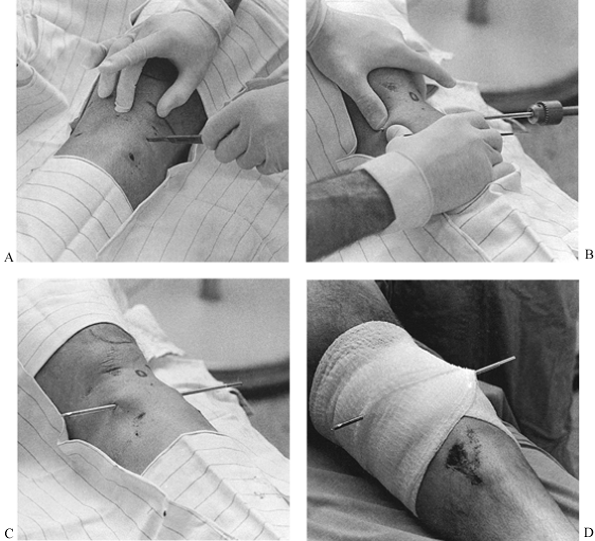 |
|
Figure 10.91. Insertion of a tibial traction pin. See text for details.
|
pads on the pin between the skin and the traction bow. This must be a
snug stack that prevents the bow from moving in relation to the leg
(illustrated in Chapter 24).
-
Use sterile technique with gloves.
Prepare the skin with an iodophor or equivalent disinfectant. Square
off the knee and proximal tibia with sterile towels. -
Always insert the pin from lateral to
medial, to minimize the risk to the common peroneal nerve.
Additionally, this technique allows the pin to be started on a bone
surface at right angles to the penetration angle of the pin. In adults,
I prefer to locate the pin at the tibial tubercle about one and
one-half finger breadths posterior to the anterior border of the fibula. -
Anesthetize the skin and deep tissues down to the periosteum with a local anesthetic.
-
Use a #11 blade to make the initial skin
incision. Here, the incision is being made transversely, but it is best
to make it vertically in the longitudinal axis of the leg. Make the
skin incision slightly smaller than the diameter of pin to be used to
produce a snug fit of the skin around the pin and to prevent sliding of
the skin on the pin, which increases the risk of infection. At the same
time, accurate location of the skin entry point to the bone portal is
essential to avoid gathering of the skin on the pin. If the latter
occurs, the skin must be incised to relieve the tension. Close the
excessive length of wound with an appropriate suture to maintain the
snug fit around the pin. -
Always insert traction pins with hand
drills, as power will produce excessive heat and kill the bone unless
the bone is predrilled (Fig. 10.91B).
Predrilling is usually not necessary and is inconvenient in the
emergency-room setting. Be certain that the tip of the pin is sharp.
Two-sided points are preferable to four-sided points. -
Push the pin down to bone and drill the pin through the tibia.
-
When the pin tents the skin on the medial
side, make a nick with the knife blade. An assistant can provide
resistance to facilitate piercing the skin with the pin. -
In Fig. 10.91C,
notice the location of the pin and the snug fit of the skin around the
pin in the absence of tension. Remember that hip and femur fractures
often lie in external rotation. Be certain to hold the leg rotationally
straight while the pin is inserted, or it will be malpositioned for
traction. -
Dress the pin with circumferential Kerlix or similar dressing (Fig. 10.91D).
Antiseptic or antibiotic solutions on the pin at the skin interface are
unnecessary. As long as the pin is properly inserted and does not
loosen, daily skin care is unnecessary. Keeping a clean sterile
occlusive dressing in place as illustrated here suffices.
It is very comfortable for the patient, as the foot is fully supported,
the traction pin is protected, the thigh is suspended independently,
and there is no traction splint or apparatus near the buttocks or groin
to interfere with personal hygiene. This modification of Charnley’s
modification of Russell’s traction (18) is
called the Western boot because it was developed at San Francisco
General Hospital, where the staff often decorated the cast to look like
a cowboy boot. In addition to being comfortable and versatile, this
method allows early motion of all joints and permits the patient to do
resistive exercises against the pull of the traction, and a continuous
passive motion motor can be attached to the thigh suspension rope to
produce continuous passive motion of the hip and knee.
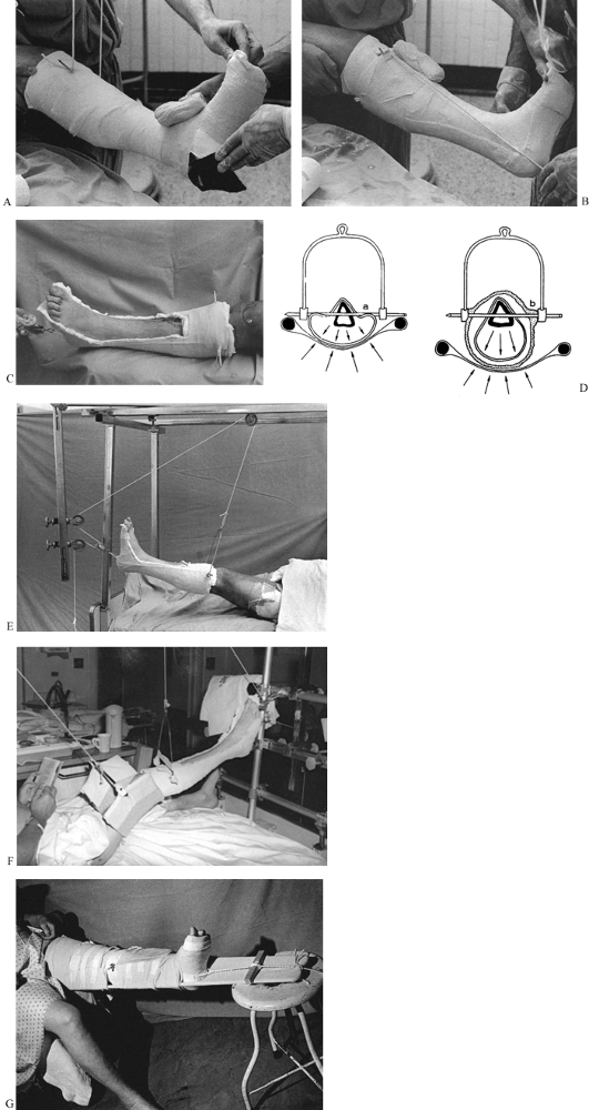 |
|
Figure 10.92. “Western boot” traction. See text for details. [(D) from Charnley J. The Closed Treatment of Common Fractures, 3rd ed. Baltimore: Williams & Wilkins, 1963.]
|
-
Insert a ¼- or 5/16-inch threaded Steinmann pin (Fig. 10.91). Place sterile 4 × 4-inch gauze pads over the Steinmann pin.
-
Prepare the extremity for application of
a short-leg cast. Use tubular stockinet and Webril as needed. The heel
and bottom of the foot are at risk for pressure sores, so place a piece
of felt over the bony prominences. -
Tie a traction rope to either side of the
Steinmann pin, long enough to extend about 2–3 inches beyond the bottom
of the foot. Tie this to the overhead bed frame to help hold the leg up
while the cast is applied. -
Now apply a short-leg cast. Begin by incorporating the leg with a roll of plaster two layers thick.
-
Once the initial two layers of
circumferential plaster have been applied, place a 10- to 15-layer
splint along the posterior aspect of the leg and foot (Fig. 10.92B). -
Place a second splint around the upper end of the cast, incorporating the Steinmann pin.
-
Bring the rope that was attached to the
Steinmann pin down alongside the cast and hold it in place opposite the
heel of the cast. -
Now thoroughly incorporate the rope and
the splints into the cast. Keep the rope sufficiently posterior that
the anterior third of the cast can be removed. -
Once the cast has been completed, slip a small pulley onto the traction rope.
-
When the cast is dry, remove the anterior half to avoid putting pressure on the foot and ankle if the cast should slip (Fig. 10.92C).
The foot can be lifted out of the cast for skin care. The bottom of the
cast supports the ankle and prevents an equinus contracture. The open
top permits active motion of the toes and ankle into dorsiflexion and
plantar flexion. -
The cast is usually not dry enough to window for several hours. Normally, I window the day after application.
-
The importance of the cast’s incorporating the Steinmann pin and surrounding the leg is illustrated in Fig. 10.92D.
-
In Fig. 10.92D,
on the left, the leg is allowed to lie on the slings on a Thomas
splint. The result is compression of the soft tissues of the leg, which
can be uncomfortable and can produce a common peroneal nerve palsy.
Distortion of the skin around the pin can cause pressure sores. In Fig. 10.92D,
on the right, the calf is suspended within the rigid cast. Suspension
prevents skin problems and minimizes the risk of common peroneal nerve
palsy. It also reduces the risk of pin-track infection by immobilizing
the pin and reducing the motion between the pin and skin. -
The completed Western boot incorporated into Russell’s traction is shown in Fig. 10.92E. The cast has yet to be given its final trim.
-
Notice that the rope and pulley
configuration is identical to that described by Russell, except the
suspension rope from the Steinmann pin inclines backward, toward the
head of the patient. This inclination is necessary to prevent the knee
from dropping into full extension. This is convenient for the patient,
as there is nothing on the thigh or buttock and groin.
length and maintain position is quite variable, depending on the size
and muscle mass of the patient, and on the hydraulic forces at the
fracture site. A good general rule
is
to apply 1 pound of traction for every 7 pounds of body weight.
Prolonged skeletal traction over 35 pounds is usually uncomfortable and
not well tolerated. In this patient, where about 25 pounds of traction
were desired, a 15-pound weight was placed on the end of the rope. The
additional weight compensates somewhat for the friction in the pulley
system. This type of traction is ideal for the pelvis, acetabulum, and
proximal femur, but it does not offer adequate stability for fractures
of the femoral shaft or supracondylar fractures.
femur, and for additional stability under other circumstances, add an
independent thigh sling (Fig. 10.92F), which
may offer sufficient stability that a shaft fracture can be treated
definitively. Additional stability may require the use of a Thomas
splint.
easily adapted for fixed traction or for fixed traction combined with
longitudinal traction (Fig. 10.92G). In this
case, the suspension ropes have been removed and a half-ring Thomas
splint has been slipped under the limb. The traction rope is tied to
the end of the splint and a windlass used to apply traction. To avoid
excessive pressure in the groin, a traction rope has been tied to the
end of the splint and a rope with a weight hung off the end of the
stool.
another hospital or ancillary diagnostic facilities. This method can be
used to get patients with multiple injuries out of bed early. For
mobilization of the patient with multiple injuries who is in traction,
I prefer roller traction.
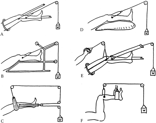 |
|
Figure 10.93. Various femur traction methods. A: Thomas splint with Pearson attachment. B: Böhler-Braun frame. C: Russell’s traction. D: Perkin’s traction. E: Fisk’s traction. F: 90-90 traction. (I prefer a distal femoral rather than a tibial pin for most 90-90 traction). (From Charnley J. The Closed Treatment of Common Fractures, 3rd ed. Baltimore: Williams & Wilkins, 1963.)
|
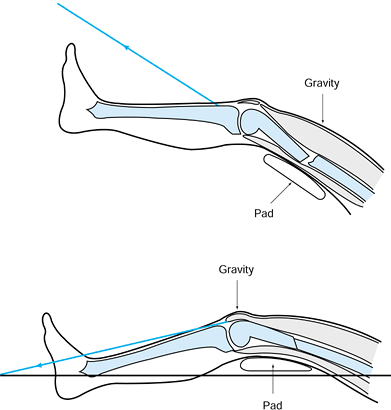 |
|
Figure 10.94. Charnley’s modification of Thomas’s traction for fractures of the femur. Top:
The line of traction is in the line of the femur, and the pad is low. Gravity causes the fracture to sag into posterior angulation. Bottom: In Charnley’s modification, the Thomas splint is placed posterior to the femur, a pad is placed under the fracture site, and the line of traction is adjusted to pull below the longitudinal axis of the femur. This results in correction of the deformity. (From Charnley J. The Closed Treatment of Common Fractures, 3rd ed. Baltimore: Williams & Wilkins, 1963.) |
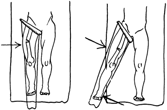 |
|
Figure 10.95. Control of varus angulation. A:
If the Thomas splint is placed in direct line with the body, varus angulation commonly occurs due to the pull of the hip abductors and iliopsoas, which pull the proximal fragment into abduction. B: This is nicely corrected by abducting the splint to bring the distal fragment into line with the proximal fragment, relaxing the muscle forces about the hip. To maintain this position, the direction of the traction line and suspension lines must be in line with and parallel to the Thomas splint. (From Charnley J. The Closed Treatment of Common Fractures, 3rd ed. Baltimore: Williams & Wilkins, 1963.) |
commonly used. The Thomas splint simply cradles the femur and plays no active role in controlling deformity.
almost never used today for the femur because of its many
disadvantages. The frame is heavy and interferes with nursing care. The
angles of the frame and the pulley positions cannot be adjusted.
Deformity is quite common because no dynamic forces can be built into
this frame for management of the alignment of the fracture.
no splintage is used at all. The limb is placed on a pillow and there
is a single traction line. Although simple, there is a major
disadvantage: When the patient lifts to get on a bed pan, the fracture
commonly angulates. We use Perkins’s traction in our intensive care
units for multiply injured patients when we want to keep the method of
treatment as simple as possible. Commonly, we combine it with a
cast-brace, which allows the nursing staff to mobilize the patient by
rolling or moving him to a bedside chair. The cast-brace provides good
stability, and a single traction line is easy for the nursing staff to
manage.
modification of Thomas’s method, allows 90° of knee movement for early
rehabilitation. A continuous passive motion machine can be attached to
the handpiece line (Fig. 10.90).
of the femur, the iliopsoas pulls the proximal fragment into flexion.
Because a tibial traction pin tends to straighten out the knee, most
surgeons prefer a femoral pin for 90-90 traction. A simple sling is
used to suspend the calf and foot.
however, is Charnley’s modification of the Thomas splint method.
Although most fractures reduce well with the simple application of
longitudinal traction in a properly applied splint, it is more humane
to do the initial application of traction, particularly if a Western
boot is to be used, in the operating room under regional or general
anesthesia. If traction alone does not result in adequate alignment,
then manipulate the fracture under anesthesia to achieve a good
reduction and make the necessary adjustments in the traction lines to
ensure maintenance of position.
maintain reduction rather than actually achieve reduction. Femoral
shaft fractures tend to heal with recurvatum (posterior angulation of
the fracture), varus of the distal fragment, and external rotation.
External rotation is easily managed by placing the tibial pin in proper
position and applying longitudinal traction. The anterior superior
iliac spine, mid patella, and first web space of the toes should be
longitudinally aligned. Any tendency for excessive external rotation
can be managed by attaching a small traction rope to the lateral side
of the traction pin and hanging on it a 1-pound weight, but it is
rarely necessary to do so.
using gravity as an assistant. Charnley emphasizes that a pad must be
placed below the fracture site, and the angle of the traction line must
be adjusted downward to impart a forward thrust at the fracture site
and a posterior thrust at the distal femur to correct the deformity.
This position is achieved by aligning the Thomas splint posterior to
the axis of the femur, placing a pad beneath the fracture site, and
adjusting the pull of the traction line to be below (posterior to) the
longitudinal axis of the femur as viewed from the side (Fig. 10.94).
To maintain this position, all traction and suspension lines should be
in the longitudinal axis of the extremity as far as the first pulley.
In Figure 10.95B, for example, the pulleys at
the foot would need to be on long bars beyond the side of the bed, and
the pulley at the upper end of the splint would need to be on the left
side of the patient for a right femur fracture. This method, as I use it, is shown in Fig. 10.96.
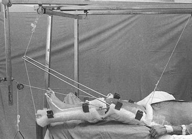 |
|
Figure 10.96. Treatment of a femoral fracture using a Thomas splint with a Pearson attachment.
|
-
Use a half-ring Thomas splint. Place the
ring on top of the thigh rather than beneath the buttocks. This
arrangement is much more comfortable for the patient and eliminates
interference with the bedpan. It is much easier to change the bed
linen, and the splint is kept much cleaner. -
Connect a Pearson attachment to the
Thomas splint to permit flexion of the knee. In supracondylar
fractures, the effect of the pad under the fracture can be mimicked by
placing the attachment of the Pearson splint at the fracture site. -
Use a commercially available single
synthetic fleece suspension sling, attached to the splints with plastic
clips, to support the limb. A pad has been placed beneath the fracture
site in Figure 10.96; note that a Western boot is in place, which provides the advantages already discussed. -
Wrap the suspension rope around the ring
of the Thomas splint twice to prevent the rope from slipping on the
ring and to allow control of rotation of the splint. In this case, the
weight has been hung at the head of the bed. I recommend hanging all
weights at the foot of the bed, because traction bars at the head of
the bed can damage the wall. Having the weights at the foot of the bed
makes them easy to adjust, as well. -
Use a single line of rope to suspend the Pearson attachment
P.300
from the Thomas splint and to suspend the Thomas splint from the
overhead frame. A clove hitch is used on the end of the Thomas splint,
which allows the angle of knee flexion to be easily adjusted without
untying any knots. In this case, a fixed line is used. -
Use pulleys and weights at the lower end
if desired to provide suspension, but they add to the complexity of the
arrangement and are usually unnecessary. The traction line in this case
passes only slightly below the longitudinal axis of the femur, as the
fracture is in the upper mid shaft. -
Place sufficient weight on the balanced
suspension so that when the patient lifts to get on a bedpan, the limb
rises easily with the torso.
needed to be maintained in traction until bridging callus was evident
on both the anteroposterior and lateral views and the fracture was
clinically stable. In the average adult, callus formation requires 6–12
weeks. At that point, we would leave the patient in balanced suspension
but remove the traction; if no shift in the fracture was noted after
several days, a single leg or 1½ spica cast would be applied and
maintained until union occurred. Because this approach requires
prolonged hospitalization and excessively long bed rest and
immobilization, cast-brace traction became popular.
as well as others. The method is called roller traction when the
cast-brace is combined with traction through a single overhead line
connected to a pulley that rolls on the overhead bar of the traction
frame (60). With this method of treatment, the
patient is much more mobile in bed and the fracture is more securely
supported. As soon as the patient is comfortable and there is early
soft-tissue stability of the fracture site (usually in 3–6 weeks), the
patient can begin to get up on crutches or a walker and begin
non-weight-bearing crutch walking a few times a day.
cast-brace, the cast-brace provides traction by virtue of gravity while
the patient is upright, producing “ambulatory traction.” Frequent
radiographic monitoring of the fracture is necessary during this
mobilization to ensure that good alignment is maintained, as angulation
is common with this technique. As soon as the patient is getting out of
bed with a physical therapist twice daily and radiographs show no
further shift in the fracture site, traction can usually be
discontinued and treatment thereafter continued in the cast-brace. When
sufficient consolidation of the fracture has occurred that shortening
can no longer occur, the traction pin can be removed and weight bearing
begun.
Vietnam War, enables the average young healthy patient to be out of
traction and discharged from the hospital by 6–8 weeks after fracture.
The cast-brace must be maintained until solid union has occurred, which
usually requires at least 10–12 weeks.
of the tibia is soft-tissue problems precluding external or internal
fixation. In addition, severe comminution, especially in the presence
of poor-quality bone, may necessitate treatment in traction to initiate
early motion of the knee or ankle. Use a traction pin through the
calcaneus or distal tibial metaphysis, as indicated. The leg can be
placed on a Braun frame, or for more convenient nursing in a Thomas
splint with a Pearson attachment for balanced suspension. In most
cases, traction is maintained for only a short time, until the
soft-tissue problems resolve and a cast or cast-brace can be applied.
The basic principles already described apply.
children are rarely treated in traction because closed reduction with
percutaneous pin fixation gives far superior results (Fig. 10.97). Rarely, operative fixation is contraindicated and treatment in traction may be necessary.
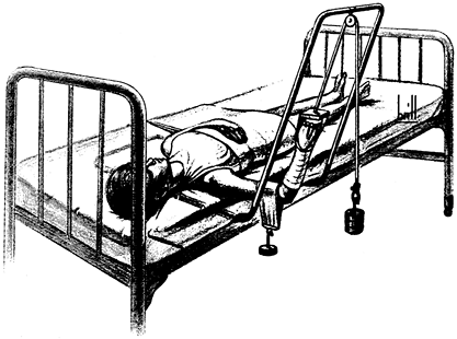 |
|
Figure 10.97.
Dunlop traction for supracondylar fractures in children, as modified by Allen and Gramse. (From W. P. Blount’s classic textbook, Fractures in Children. Baltimore: Williams & Wilkins, 1955:279.) |
-
First, apply skin traction to the forearm using the techniques described for modified Buck’s traction.
-
Leave the hand and fingers free for neurovascular examination. The radial pulse should be accessible.
-
It is usually best to place the patient in the orthopaedic bed (Fig. 10.97)
in which she will be immobilized and to perform the closed reduction in
that bed to prevent loss of reduction when she is moved from the
operating table to the ward bed. -
Reduce the fracture, then apply sufficient traction from the forearm to hold the arm level with the floor.
-
Fashion a sling for the arm from a
commercial fleece sling or from felt inserted into tubular stockinet.
It must be sufficiently wide that at least the lower third of the arm
is covered. -
Attach to it sufficient weight to maintain reduction (rarely more than 1–2 pounds).
-
To avoid malrotation and varus or valgus
alignment, the patient’s torso must be maintained in correct
relationship to the line of traction.
indicated today; I have not used it since the early 1980s. Most
fractures of the humerus are now better managed with external or
internal fixation. Rarely, a particular combination of systemic disease
and soft-tissue and bone problems may necessitate treatment in overhead
traction. An example might be a fracture of the humerus associated with
burns, in which overhead traction may be the optimal method.
-
Using sterile techniques, place an
appropriate-size K-wire transversely through the olecranon. Always
insert this pin from medial to lateral, taking care to avoid injury to
the ulnar nerve. In Figure 10.98 the pin is
not dressed, but I advise placing sterile 2 × 2-inch gauze pads between
the skin and the K-wire bow to protect the pin entry site, and to
prevent the bow from sliding back and forth. If the bow slides toward
the medial side of the forearm and impinges on the ulnar nerve, ulnar
nerve palsy and erosion of skin and nerve can occur.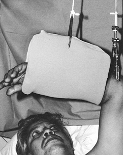 Figure 10.98. Overhead olecranon pin traction.
 -
Apply sufficient traction to maintain appropriate length and the reduction.
-
Suspend the forearm with a sling. The
sling here is rather large. Smaller slings that can be more easily
removed may facilitate physical therapy and hand function.
recommendations for avoiding complications of traction, which follow
the principles of those for casts and splints. Generalized
cardiovascular deconditioning and atrophy of muscle occur very rapidly
in
patients
on complete bed rest and traction. The physical therapist should visit
all patients in traction within the first few days of treatment to
initiate a physical therapy program for maintenance of cardiovascular
conditioning and joint range of motion and strength. Stretching
exercises, particularly of the Achilles tendon, are necessary to avoid
contractures. Splinting may be necessary.
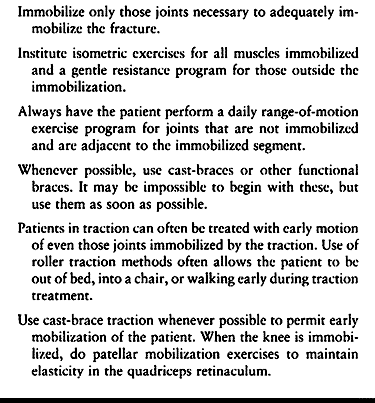 |
|
Table 10.2. Avoiding Complications of Traction
|
light weights or elastic bands will help maintain muscle strength. All
joints that can be moved through a full range of motion passively or
actively without interfering with the treatment of the fracture or
dislocation should be exercised vigorously throughout the day.
Cardiovascular conditioning is very difficult to maintain while in
traction, but a general exercise program is very helpful. It is usually
possible to move the joints to some extent and to do isometric
exercises of the muscles above and below the fractured bone; encourage
the patient to do so as soon as possible.
careful attention to the techniques described. Remember that excessive
traction on a swollen limb can precipitate compartment syndrome. If
symptoms develop, reduction of the traction may be necessary.
factor is an active, vigorous patient who frequently does pull-ups on
the overhead frame to allow good circulation to the skin. Good nursing
care to maintain a clean perineum and dry sheets is imperative. An
egg-crate foam mattress or similar device should routinely be used, and
alternated with an air mattress if necessary. The more complicated beds
used for the care of quadriplegics are rarely practical with traction.
rest, and secondary pulmonary embolism can be fatal. Some type of
prophylaxis is indicated in nearly all patients (see Chapter 5 for more details).
adjusted. It requires constant attention to maintain optimal alignment
and position, ensure patient comfort, optimize nursing care, and
prevent complications.
scheme: *, classic article; #, review article; !, basic research
article; and +, clinical results/outcome study.
SE, Robb BA, Taylor WF, Kelly PJ. Effect of Fixation with
Intramedullary Rods and Plates on Fracture Site Blood Flow and Bone
Remodeling in Dogs. J Bone Joint Surg Am 1977;59:376.
I, Somjen D, Shimshoni Z, et al. Stimulation of Skeletal-derived Cell
Cultures by Different Electric Field Intensities Is Cell Specific. Biochem Biophys Acta 1985;844:273.
CT, Friedenberg ZB, Black J. Evaluation of the Use of Constant Direct
Current in the Treatment of Nonunion. In: Brighton CT, Black J, Pollack
SR, eds. Electrical Properties of Bone and Cartilage. Experimental Effects and Clinical Applications. New York: Grune & Stratton, 1979:519.
J, King P. Closed Reduction and Early Cast-Brace Ambulation in the
Treatment of Femoral Fractures. Part I: An In Vitro Quantitative
Analysis of Immobilization in Skeletal Traction and a Cast-brace. J Bone Joint Surg Am 1973;55:1559.
J, Naparstek E, Slatter M, et al. Osteogenic Response to Marrow
Aspiration: Increased Serum Osteocalcin and Alkaline Phosphatase in
Human Bone Marrow Donors. J Bone Miner Res 1989;4:643.
AE. The Treatment of Femoral Fractures by Cast-Brace Application and
Early Ambulation. A Prospective Review of 106 Patients. J Bone Joint Surg Am 1983;65:56.
Historiques et Pratiques sur les Appareils Employés dans le Traitement
des Fractures en Général Depuis Hippocrate jusqu’à Nos Jours. Paris: H. Cousin, 1841.
Y, Kestenbaum RS, Galinsky D, Shany S. Seasonal Variation in Serum
Levels of Vitamin D Metabolites and Parathormone in Geriatric Patients
with Fractures in Southern Israel. Isr J Med Sci 1986;22:8.
Y, Kestenbaum RS, Schany S, et al. Parathormone, Calcitonin, and
Vitamin D Metabolites During Normal Fracture Healing in Geriatric
Patients. Clin Orthop 1985;199:272.
AGSA, El Attar S, Mili F, Wright EA. The Effect of Environmental
Temperature on the Rate of Healing of Fractures in Tail Vertebrae of
Mice. J Bone Joint Surg Br 1980;62:102.
Hodgen Wire Cradle Extension Suspension Splint: The Exemplification of
This Splint with Other Helpful Appliances in the Treatment of Fractures
and Wounds of the Extremities and Its Application in Both Civil War and
Practice. St. Louis, MO: CV Mosby, 1918.
LA, Bourret LA, Rodan GA. Molecular Changes in Hard Tissue Cells in
Response to Bioelectric Proliferative Signals. In: Becker RO, ed. Mechanism of Growth Control. Springfield, IL: Charles C. Thomas, 1981:180.
MW, Palmieri VR, Cochran GVB. Transcortical Streaming Potentials Are
Generated by Circulatory Pressure Gradients in Living Canine Tibia. J Orthop Res 1990;8:119.
RR, Schemitsch EH. Effect of Muscle Flap Coverage on Bone Blood Flow
Following Devascularization of a Segment of Tibia. J Orthop Res 1989;7:550.
HK, Bardos DI, Liskova-Kiar M. The Advantages of Titanium Alloy over
Stainless Steel Plates for the Internal Fixation of Fractures. J Bone Joint Surg Br 1981;63:427.