
frequency for fracture care in the Western world, a knowledge of these
effective principles is necessary for special indications or situations
in which equipment or expertise is not available or patient
comorbidities do not permit operative intervention.
-
Traction maintains the length of a limb as well as alignment and stability at the fracture site. Treating femoral fractures with fixed skeletal traction is an example.
-
Traction can allow joint motion
while maintaining alignment of the fracture. For example, the Pearson
attachment on a Thomas splint allows knee movement during traction
treatment of a femoral fracture; overbody or lateral skeletal traction
allows elbow motion while maintaining alignment of a humeral fracture. -
Traction can overcome muscle spasm
associated with bone or joint disease. An example is Buck traction,
which is sometimes recommended for patients with hip injuries. -
Edema is reduced in an extremity by a traction unit that elevates the affected part above the heart.
Elevate the head or the foot of the bed by using either shock blocks or
the bed’s intrinsic elevation system. Attach an overhead frame,
trapeze, and side rails to the bed so the patient can shift position.
Traction equipment includes bars, pulleys, ropes, weight hangers,
skeletal traction apparatus, and, in some instances, plaster cast
materials. Various figures in this chapter show the type and placement
of equipment about the bed.
-
Skin traction may be used as a definitive method of treatment as well as a first aid or temporary measure. The traction force
applied to the skin is transmitted to bone via the superficial fascia,
deep fascia, and intermuscular septa. Skin damage can result from too
much traction force. The maximum weight recommended for skin traction
is 10 lb or less, depending on the size and age of the patient. If this
much weight is used, then discontinue the skin traction after 1 week.
If less weight is used and if the skin is inspected biweekly, then skin
traction may be safely used for 4 to 6 weeks. Pediatric patients need
skin inspection on a more frequent basis. -
Application
-
Carefully prepare the skin by removing the hair as well as washing and drying the area.
-
Avoid placing adhesive straps over bony prominences.
If bony prominences are in the area of strap application, cover them
well with cast padding before the adhesive straps are applied. Always
use a spreader bar to avoid pressure from the traction rope on bony
prominences. -
Make the adhesive straps
from adhesive tape, moleskin adhesive, or a commercial skin traction
unit consisting of foam boots with Velcro straps. Place the straps
longitudinally on opposite sides of the extremity, with free skin left
between the straps to prevent any tourniquet effect. Attach the free
ends of these straps to the spreader bar. Hold the straps in place by
encircling the extremity with an adhesive or elastic wrap. Then apply
the traction rope to the spreader bar. -
Support the leg in traction with pillows or folded bath blankets to prevent edema and irritation of the heel.
-
-
Definition. Skeletal traction is applied through direct fixation to bone.
-
Equipment
-
Kirschner wire
is a thin, smooth wire that is 0.0360 to 0.0625 in. in diameter. The
advantages of Kirschner wire are that it is easy to insert and that it
minimizes the chance of soft-tissue damage or infection. The
disadvantage is that it rotates within an improper bow and can cut
through osteoporotic bone. These complications are minimized by using
the proper traction bow. Even though Kirschner wire is small in
diameter and flexible, it can withstand a large traction force when the
proper traction bow is used. This special bow (Kirschner bow) provides
the wire with rigidity by applying a longitudinal tension force (Fig. 9-1).
If properly placed and not improperly stressed, the wire does not break
and causes less bone damage than the larger Steinmann pins. -
Steinmann pins
vary from 0.078 to 0.19 in. in diameter and come in smooth and threaded
forms. Because they are large enough to have inherent stability, the
Steinmann pin bow (Böhler bow), which attaches to these pins, does not
exert tension along the pin as does the Kirschner traction bow. The two
types of pins should be readily recognized and used with the
appropriate bow (Fig. 9-1). -
Factors to be considered
-
A nonthreaded wire or pin
is smaller, more uniform, less easily broken, more easily inserted, and
removed with less twisting than the threaded type. A disadvantage is
that it can slide laterally through the skin and bone. Even with
careful attention, it can move enough to disturb the traction or
predispose to a pin tract infection. -
The threaded wire or pin
has stress risers at each thread, breaks more easily, must be larger in
diameter to gain the same strength, and takes a longer time to insert.
In inserting a threaded pin, one is tempted to go rapidly with the hand
drill, which creates an undue amount of heat. On the other hand,
because the threads prevent lateral slippage of the pin, this type is
preferable to the nonthreaded variety for long-term (longer than 1–2
weeks) traction.
-
-
The wires and pins are available with two types of points. One is a trocar, a blunted point that tends to grind through the bone with relatively little cutting ability. The other is a diamond-shaped point,
a modified type of drill that passes through bone more easily and with
less heating. Wires and pins that are dull, sharpened off-center, or
bent should not be used. These wander during insertion and create a
hole that is too large. -
Note that pins and wires are frequently used as internal fixation devices for fractures; such use is discussed in Chap. 10 and the chapter on hand fractures.
-
-
Pin and wire insertion guidelines
-
Pin or wire insertion is a surgical procedure, so some form of consent
is needed, at least with a witness in attendance who signs a note in
the chart attesting that informed consent was obtained. A signed,
witnessed surgical consent is preferred. -
Establish the status of neurovascular structures
before inserting the pins. Placement of the pins requires knowledge of
the specific anatomy and the location of vital structures. Rule:
Always start the pin on the side where the vital structures are
located. This gives better control and better avoidance of these
structures. For instance, start an olecranon pin on the medial side to
avoid the ulnar nerve. -
Skin preparation.
The skin should be free of signs of infection. Follow aseptic
procedures, using a topical germicidal antiseptic, drapes, mask, and
gloves. -
It is difficult to obtain enough anesthesia
to block the periosteum completely. Anesthetize the skin and
subcutaneous tissue with 1% lidocaine on the starting side of the bone.
Go down to the periosteum with the needle tip and insert enough
lidocaine around this area to produce some anesthesia. If there is pain
as the pin is inserted and approaches bone, then inject more
anesthetic.
P.139
Drill
the pin approximately halfway through the bone, get an idea where it
will come out, and then anesthetize the opposite side. In a case in
which the wire penetrates two bones, such as the tibia and fibula, it
is impossible to anesthetize the area between the two bones. Tell the
patient ahead of time that this may be painful for a few seconds but
that as soon as the drilling stops, the pain will cease. If done in the
emergency department, conscious sedation should be utilized.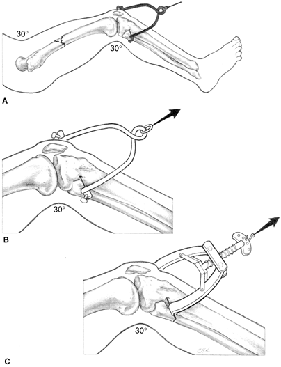 Figure 9-1. Traction bows. When using skeletal traction to treat femoral fractures, the knee is kept in slight flexion (A).
Proximal tibial traction is reserved for adults. To avoid physeal
injury in children with resultant recurvation deformity, distal femoral
traction proximal to the distal femoral physis is used. For larger
Steinmann pins, a Böhler bow is used (B). The tensioning capabilities of the Kirschner bow allows the use of smaller Kirschner wires (C). -
Skin incision.
When starting the procedure, pass the wire or pin through a stab wound
made with a no. 11 blade. If only a puncture wound is made by
P.140
the pin, then tight
skin adherence to the pin predisposes to an infection. If an infection
with abscess does occur, then drain it by extending the stab wound.
Dress the pin site with sterile 4 × 4s on each side with Betadine
solution applied. -
Pins and wires should be inserted using a hand drill
rather than a power tool. The time saved by using power equipment is
expended in preparation time. There is also a tendency to use too high
a speed with power drills and generate too much heat, thereby promoting
development of bone necrosis around the pin insertion, resulting in a
ring sequestrum. The smaller the pin and the slower the rotation of the
hand drill, the faster the pin is inserted. Adequate support of the
limb from adequate help must be available so that, as the pin is being
inserted, the limb does not shift and cause the patient further pain. -
Traction wires or pins are best placed in the metaphysics,
not in dense cortical bone. Use caution to avoid epiphyseal plate
damage, which can result in a growth disturbance. In skeletally
immature patients, the pin should be inserted under fluoroscopic
control to avoid the physis. In the area of the tibial tubercle, assume
in female patients younger than 14 years old and in male patients
younger than 16 years old that the epiphyseal plate is open. Because of
the risk of physeal injury in the proximal tibia, choose the distal
femur for skeletal traction in younger patients if possible. Ideally,
pass the pin through only skin, subcutaneous tissue, and bone. Avoid
muscles and tendons. -
Do not violate a fracture hematoma by skeletal wires or pins for traction or else the equivalent of an open fracture will result.
-
Do not penetrate joints
with traction wires or pins as pyarthrosis can occur. Do not enter the
suprapatellar pouch with distal femoral wires or pins. Here again,
inserting the pin under fluoroscopic control can avoid these
complications. -
Points to remember about wire or pin insertion:
-
Chuck the wire or pin so that just 2 to 4 in. are exposed to prevent wandering and bending.
-
Tighten chuck sufficiently to prevent score marks that are sources of metal corrosion and fracture.
-
Be certain the wire does not bend as it is inserted.
-
Use the proper traction bow (Fig. 9-1).
-
-
-
Specific areas of insertion
-
Metacarpals.
Place the wire through the metaphyseal diaphysed junction of the index
and middle metacarpals. To facilitate insertion, push the first dorsal
interosseous muscle in a volar direction and palpate the subcutaneous
portion of the bone. Angle the wire to pass through the index and
middle metacarpals and to come out the dorsum of the hand, so as to
preserve the natural arch. -
Distal radius and ulna. Usually place the wire or pin through both the radius and the ulna. This site is rarely used.
-
Olecranon.
Take care to avoid an open epiphysis. Do not place the pin too far
distally because this causes elbow extension, and it is more
comfortable to pull through a flexed elbow than an extended elbow. Use
a moderate-sized wire or pin and insert from the medial side to avoid
the ulnar nerve. Use a very small traction bow. -
Distal femur.
Start on the medial side, anterior enough to avoid the neurovascular
structures. This insertion is best accomplished by placing the pin 1
in. inferior to the abductor tubercle. If the pin will be used for
traction on a fracture table for delayed intramedullary nailing, make
sure it is placed far anterior, off the coronal midline to avoid
incarceration by the intramedullary nail. Fluoroscopy should be used to
help the surgeon avoid an open physis. -
Proximal tibia.
Place the wire or pin 1 in. inferior and 1/2 in. posterior to the
tibial tubercle, starting on the lateral side to avoid the peroneal
nerve. Take extreme care to avoid an open epiphysis; if the anterior
portion of the proximal tibial epiphyseal plate is violated, genu
recurvatum can occur. -
Distal tibia and fibula.
Start the pin 1 to 1 1/2 fingerbreadths above the most prominent
portion of the lateral malleolus to avoid the ankle mortise. Insert it
P.141
parallel
to the ankle joint and angulate it slightly anteriorly. The surgeon
should feel the pin pass through the two fibular cortices and then the
two tibial cortices. Pass the pin through both bones to avoid the
tendons and neurovascular structures. If the pin is placed too far
proximally, the foot rests on the bow, and a pressure sore may occur. -
Calcaneus.
Generally select a large diamond-point pin. The preferred insertion
site is 1 in. inferior and posterior from the lateral malleolus or 1
3/4 in. inferior and 1 1/2 in. posterior from the medial malleolus.
Because of the position of the tibial nerve, the medial starting site
is preferred. If the pin is placed too far posteriorly, it causes a
calcaneal position of the foot. If the pin is placed too far
inferiorly, it may cut out of the bone. If the pin is placed too far
superiorly, it can enter the subtalar joint and also spear the flexor
tendons or tibial nerve and/or artery. Infections that are difficult to
treat often occur when the calcaneus is used for long-term traction.
-
-
Neck halter traction
is the simplest of the different types of cervical spine traction but
usually is not used in the treatment of acute cervical spine fractures
or dislocations, being reserved for chronic conditions such as a
cervical radiculopathy. Apply the traction to the mandible and occiput
with a soft, commercially made halter.-
When continuous traction
is used with the patient in the supine position, do not exceed 10 lb (5
lb is usually sufficient). With the patient sitting, approximately 8 lb
may be added to the attached weight to account for the weight of the
head. The total attached weight should not exceed 15 lb with the
patient in the sitting position. The traction should not be strictly
continuous but used for 1 to 3 hours followed by rest intervals to
allow jaw motion and to relieve pressure on the skin. -
If intermittent traction for short periods of time is used three times daily, then up to 30 lb may be used.
-
Problems
associated with head halter traction are related to the weight used and
the position of the neck. The optimum position is usually neutral or in
slight flexion. Temporomandibular joint discomfort can ordinarily be
relieved by changing the direction of traction force or decreasing the
attached weight. Symptoms from local skin pressure may be relieved by
the above methods or by appropriate padding.
-
-
Skull tong traction is a form of cervical spine traction and is applied by one of the many types of skull calipers (tongs) (Fig. 9-2). The most satisfactory caliper is
P.142
screwed into the skull without the need for previous trephining and
does not penetrate more than a preset depth. The Gardner-Wells tongs
are recommended (Fig. 9-3) (1).
With this type of apparatus, heavy traction can be applied to the skull
for as long as required. It is especially useful for cervical spine
fractures and dislocations. Perform the following procedures after the
scalp is cleaned and draped; local shaving is sufficient but is not
absolutely mandatory.![]() Figure 9-2.
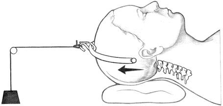
Figure 9-2.
Tong traction. This treatment is used for most cervical fractures and
dislocations. The points are positioned just above the ear pinnae.
Padding can be used to generate more flexion or extension of the
cervical spine as is indicated for reduction based on lateral cervical
roentgenograms.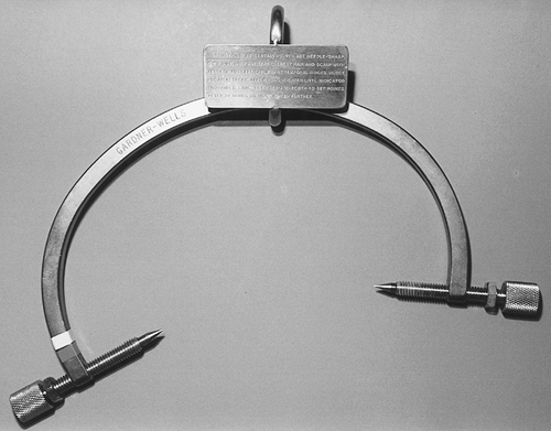 Figure 9-3. Gardner-Wells tongs.
-
The Gardner-Wells skull traction tongs
are easy to insert. After preparing the skull, position the tongs below
the temporal crest and tighten. A spring device within the tong points
automatically sets the correct depth and tension. Then the indicator
protrudes 1 mm from the knob of the tong, at which time the correct
pressure (equivalent to 6–8 in./lb) is exerted. Retighten these pins in
a sequential manner to the same value the next day, and then do not
tighten them again unless loosening occurs. -
Keep the head end of the frame slightly elevated so the patient’s body acts as countertraction.
-
Initiate cervical traction at 10 to 15 lb
and incrementally increase only after checking the appropriate
roentgenograms. Initiating traction at higher weights can occasionally
result in marked distraction of ligamentous injuries. For definitive
traction, Crutchfield’s rule of 5 lb/level starting with 10 lb for the head allows for a maximum range of 30 to 40 lb for a C5–C6 injury.
-
-
Fixed halo skull traction. The halo device, originally introduced by Nickel and Perry (2,3), can be used alone for traction or combined with a vest or cast.
-
Materials
-
Application procedures are modified from those described by Young and Thomassen (4) and Botte et al (2).
-
Shave and trim hair
around the pin sites (optional). The pin sites should be 1 cm above the
lateral third of the eyebrow and the same distance above the tops of
the ears in the parietal and occipital areas. Place the halo just
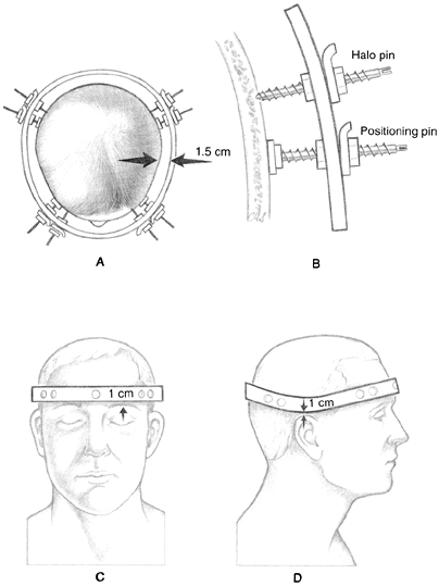
inferior to the greatest circumference of the head (Fig. 9-4).![]() Figure 9-4. Principles of a halo ring application. The correct ring size allows for 1.5 cm of clearance (A). Positioning pins are used to stabilize the ring while the skull pins are inserted (B). The proper position of the ring is 1 cm above eyebrows and ear pinnae (C, D).
Figure 9-4. Principles of a halo ring application. The correct ring size allows for 1.5 cm of clearance (A). Positioning pins are used to stabilize the ring while the skull pins are inserted (B). The proper position of the ring is 1 cm above eyebrows and ear pinnae (C, D). -
Position the patient supine on a bed with the head extended beyond the edge. Have the head supported by an assistant’s hands or by a 4-in. wide board placed under the head and neck.
-
Place a sterile towel under the patient’s head. This step is not necessary if an attendant is holding the head.
-
Select a halo ring that allows for 1.5 cm clearance. If MRI studies are anticipated, then an MRI-compatible ring and pins must be used (carbon fiber material).
-
The halo ring, skull pins, and positioning pins should be autoclaved or gas sterilized.
-
The assistant, wearing gloves, positions
the halo ring around the head with the raised portion of the ring over
the posterior part of the skull. Use positioning pins and plates to
place the ring in the proper attitude and to equalize the clearance
around the head. -
Infiltrate the skin with an anesthetic at the four pin sites.
-
The skull pins
should be at a 90-degree angle to the skull and turned to finger
tightness. The skull pins are designed so that no scalp incisions or
drill holes are needed. The shape of the point draws the skin under it
and does not cause bleeding. Try to avoid puckering of the skin at the
pin site. If puckering does occur, then remove the pins, flatten the
skin, and repenetrate. -
Both operators use the torque screwdrivers
simultaneously, turning opposing skull pins. Gain increments of 2
in./lb evenly up to the maximum desired by the physician. A suggested
maximum is 4 1/2 in./lb for children and 6 to 8 in/lb for adults. -
Remove the positioning pins.
-
Incorporate the support rods of the halo apparatus into the plaster body jacket, as shown in Fig. 7-5, or use a sheepskin-lined molded plastic body jacket that is commercially available or custom made by an orthotist (Fig. 7-6).
-
Tangential roentgenographic views
of the skull or a computed tomography (CT) scan can be ordered to check
the depth of the skull pins but are not routinely necessary.
P.144 -
-
Care of pin sites
-
Clean around the pins with peroxide solution using a cotton swab twice daily.
-
Check the torque of the pins for the first few days. Note:
If the patient complains of repeated looseness or if the proper torque
cannot be gained, then move the pin to another place on the ring by the
aforementioned method. Do not remove a loose pin until the fifth
replacement pin is inserted.
-
-
-
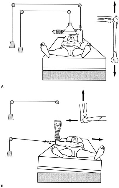
Dunlop or modified Dunlop skin traction. This type of traction is occasionally useful for the management of supracondylar humeral fractures (5).
Place the patient supine and suspend the arm in skin traction with the
shoulder abducted and slightly flexed. In addition, slightly flex the
elbow. Modification of this type of traction provides counteraction on
the humerus, which can be achieved with the arm over the edge of the
bed and counterweight suspended from a felt cuff over the humerus, or
with a felt cuff over the forearm pulling laterally with the elbow
flexed (Fig. 9-5).
Two disadvantages of Dunlop traction are that it cannot be applied over
skin injuries and that elevation of the humeral fracture above the
level of the heart is not possible with this method. -
Overbody or lateral skeletal traction
-
In the management of extraarticular
humeral shaft and metaphyseal fractures, it is occasionally desirable
to maintain the shoulder in flexion without abduction but with the
elbow at a right angle by placing the arm over the body. Maintain this
position through olecranon skeletal traction, which allows some flexion
and extension of the elbow if the traction pin is properly inserted.
Because the
P.145
hand
and wrist usually tire in this position, support the wrist with a
plaster splint. Skeletal traction through the olecranon may also be
used in the lateral position (Fig. 9-6).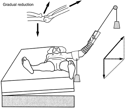 Figure 9-5.
Modified Dunlop traction. A weight of 1 to 5 lb is usually required.
Associated circulatory embarrassment might be aggravated by increasing
elbow flexion. -
A special, rarely used adaptation of upper extremity olecranon traction may be made by placing the patient in a shoulder spica cast
that incorporates an olecranon pin into the plaster to apply fixed
skeletal traction. This adaptation allows the patient to be ambulatory.
-
-
Apply Buck extension skin traction (Fig. 9-7)
to the lower extremity to reduce muscle spasms about the knee or hip.
However, do not use this form of traction for back conditions. Control
rotation to some extent by placing the leg on a pillow with sandbags on
the lateral side of the ankle. Although Buck traction is commonly
recommended for hip fractures, its use should be limited in duration.
For intracapsular fractures, keep the hip flexed to increase hip
capsule volume and thereby limit pain. The effectiveness of this type
of traction in decreasing pain has not been demonstrated (6,7). -
Hamilton-Russell traction (Fig. 9-8)
may be used for hip or femoral fractures, especially in children
weighing 40 to 60 lb. Accomplish the traction with either skin traction
or distal tibial skeletal traction plus a sling placed beneath the
posterior distal thigh (avoid pressure in the popliteal fossa). A rope
is attached to the sling and goes first to an overhead pulley, then to
a pulley at the foot of the bed, next to a pulley on the foot plate
attached to the spreader bar, then to a fourth pulley at the end of the
bed, and finally to the attached weight. Analysis of the vector forces
shows that the traction applied to the leg is increased considerably by
moving the overhead pulley toward the foot of the bed. If this type of
traction is used on a child, one usually attaches 3 lb to the traction
apparatus. Produce a countertraction with the patient’s body weight by
elevating the foot of the bed.![]() Figure 9-6. Olecranon pin traction. A:
Figure 9-6. Olecranon pin traction. A:
Overbody traction. Note that the elbow joint can move without
disturbing the fracture. The hand and wrist rest in a plaster splint. B: Lateral traction.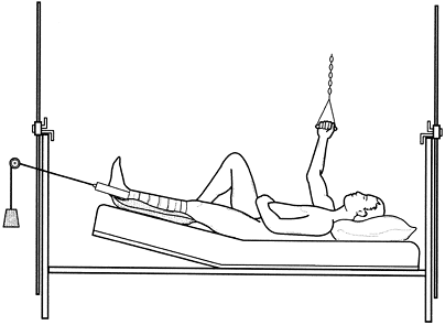 Figure 9-7.
Buck extension skin traction. Note elevation of the foot of the bed and
support under the calf. Protect the fibular head and malleoli. A weight
of 5 to 7 lb of traction is sufficient.![]() Figure 9-8.
Figure 9-8.
Hamilton-Russell traction. Note that the resultant force on the femur
is a summation of vector analysis and depends on the position of the
overhead pulley. Change the angulation of the distal fragment by moving
the single overhead pulley. -
Split Russell traction
has the same indications and vector forces as Hamilton-Russell
traction. The difference is that split Russell’s traction uses two
separate ropes and weights, as shown in Fig. 9-9. -
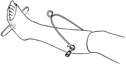
Charnley traction unit (boot) is useful for applying skeletal traction to a lower limb and is recommended for routine use (Fig. 9-10).
This limits rotational forces on the limb controlling alignment,
maintains the ankle in neutral position, and limits the stress on the
traction bow. The unit is assembled by inserting a wire or pin through
the proximal end of the tibia and then incorporating the wire or pin in
a short-leg cast. The advantages are as follows:-
The foot and ankle are maintained in a neutral functional position.
-
The limb is suspended in a cast, and there is no pressure on the calf muscles or peroneal nerve.
-
Movement of the skeletal pin or wire is reduced to a minimum.
-
-
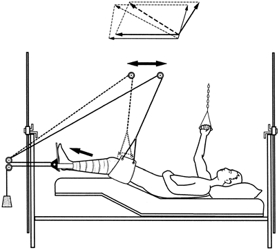
Balanced suspension skeletal traction
provides a direct pull on either the tibia or the femur through a wire
pin. Rest the lower extremity on a stockinet or a cloth towel stretched
over a Thomas splint. The splint, with or without a Pearson attachment,
is balanced with counterweights to suspend the leg in a freely floating
system. Attach separate suspension ropes to both sides of the proximal
full ring
P.149
Thomas
splint, run the ropes through overhead pulleys, and fasten weights to
ropes at either end of the bed but not over the patient. Control
rotation of the ring by individually adjusting the amount of attached
weight. Suspend the distal end of the splint from a single rope to an
overhead pulley, with the weight attached to the rope at one end of the
bed. For safety reasons, place no weights over the patient. Control
rotation of the extremity by a light counterweight attached to the side
of the splint or by a crossbar attached to the plaster cast. The
Charnley traction unit (boot) is ideally suited for both balanced
suspension and fixed skeletal traction (which is discussed next) (Fig. 9-11). A Pearson attachment
allows for flexion motion of the knee joint, which is an advantage,
especially for those in traction for a long period of time or for those
who have a comminuted tibial plateau fracture.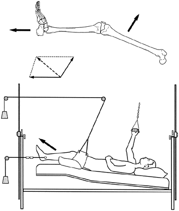 Figure 9-9.
Split Russell traction is the same as Hamilton-Russell traction except
that two separate ropes and weights are used instead of one.![]() Figure 9-10.
Figure 9-10.
Charnley traction unit consisting of a skeletal wire or pin
incorporated into a short-leg cast, which has a crossbar fixed to the
sole. The unit is commonly employed for femoral fractures treated with
skeletal traction.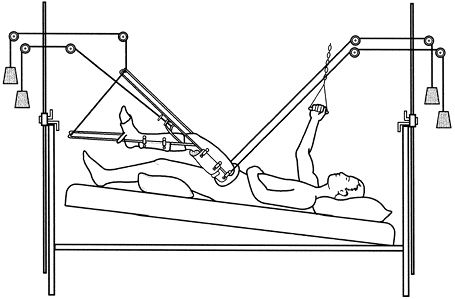 Figure 9-11.
With balanced suspension traction, the various weights are adjusted
until satisfactory alignment and suspension of the femoral fracture are
achieved within the Thomas splint. Note the Charnley traction unit,
firm mattress, bed board, and master pad. Wrap an elastic bandage about
the thigh and splint to minimize the acute swelling. -
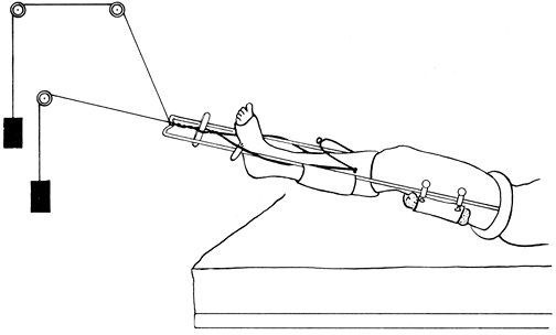
Use fixed skeletal traction
in the initial treatment of femoral fractures in patients who will go
on to intramedullary nailing or who need to be transported either in
the hospital or to another facility.-
In the rare situation in which the fracture must be reduced, the apprehensive patient or the patient with a transverse fracture usually requires general or regional anesthesia.
-
Apply the Charnley traction unit to the lower leg.
-
Select a full or half ring Thomas splint that is 2 in. greater than the proximal thigh (8).
This leeway is critical because a ring that is too tight causes distal
edema and one that is too loose is ineffective. The ring must fit
against the fibrofatty tissue in the perineum and the medial arch of
the buttocks. The half ring is placed against the ischium and the strap
tightened loosely against the anterior thigh. -
While the leg is supported in traction, place the ring on the limb. Attach a single master sling
of nonextensible cloth (a double-thickness cloth towel is ideal)
measuring 6 to 9 in. long to the splint beneath the fracture. Adjust
tension to support the limb. If the sling is too tight, then it causes
excessive flexing of the proximal fragment; if it is too loose, then it
does not control the fracture. Attach this sling to the splint with
several clamps. -
Make a supporting or master pad that is 1
to 1 1/2 in. thick and 6 to 9 in. long from an abdominal dressing or a
folded towel. Insert a safety pin into the pad to assist localization
of the pad on roentgenograms. Place this pad beneath the fracture and
adjust it to maintain the normal anterior bow of the femur. A single
sling is placed on the Thomas splint distally to support the short-leg
cast. -
Check the reduction.
End-on reduction for transverse fractures is ideal in the adult; take
care to avoid distraction of the fracture. If the patient will have
delayed intramedullary nailing, maintain some distraction, which will
aid in intraoperative reduction. In the child, bayonet apposition is
preferred. With the oblique fracture, it is important to feel
bone-on-bone contact to be certain there is no soft-tissue
interposition. If there is interposition, then it can usually be
dislodged by manipulation. Then assess length, alignment, and
rotational positions and attach traction to the end of the splint.
Extend two ropes from the Steinmann pin around the sides of the splint
and attach them to the splint end. Tape two tongue blades together to
form a Spanish windlass to adjust tension. After the first day or two,
when muscle spasm subsides, only slight traction is necessary to
maintain the appropriate alignment. It might not be possible to gain
full length initially because of unusual tense swelling of the thigh.
Attach a second pad or C-clamp to add cross-traction if needed for
better alignment, particularly in the more transverse fracture patterns. -
Suspend the splint to allow patient mobility in bed and to reduce edema. Figure 9-12 depicts the completed setup.
-
Follow-up care,
particularly in the first few weeks, is important. Wash the skin
beneath the ring daily with alcohol, dry thoroughly, and powder with
talc every 2 hours. The conscious patient may perform this care each
hour and massage the skin to improve blood supply. If it is necessary
to relieve skin pressure under the ring, then apply traction directly
from the end of the splint; slight distraction is preferred when
intramedullary nailing is to be delayed for more than 24 hours. Be
careful, however, not to cause distraction at the fracture site when
using fixed skeletal traction as the definitive treatment. Start
quadriceps exercises within the first few days and continue on an
around-the-clock basis. All the elements outlined earlier are essential
for effective utilization of fixed skeletal traction.
-
-
An infection
of the pin tract is a common complication, but its incidence is reduced
when the previously stated guidelines for pin and wire insertion are
carefully followed. If an infection with a small sequestrum occurs, it
is wise to
P.151
remove
the pin, curette the pin tract, and replace the pin in the operating
room under adequate anesthesia. The infection usually subsides
satisfactorily with antibiotic therapy.![]() Figure 9-12.
Figure 9-12.
Fixed skeletal traction. Note the Charnley traction unit, the method of
adjusting traction force via the windlass, the position of the master
pad, and the traction on the end of the Thomas splint to relieve skin
pressure on the proximal thigh. Place an elastic bandage around the
thigh and splint to help control edema. -
Distraction
of bone fragments at the fracture site is avoided by frequently
measuring extremity length, by using roentgenograms to check the
position of fragments, and by keeping traction to a minimum.
Distraction is best assessed by lateral roentgenograms because
anteroposterior roentgenograms may not be perpendicular to the fracture
and may underestimate the distraction. Distraction can predispose to a
delayed union or nonunion of the fracture. -
Use heavy traction with care and close observation to avoid nerve palsy. If paralysis does occur, adjust and possibly abandon the traction.
-
Pin breakage
is unusual but can occur if very heavy traction is used for long
periods, especially in a restless patient. To protect the pin,
incorporate it into plaster in the manner of the Charnley traction
unit. Decrease the potential of metal corrosion and fracture by using a
wire or pin that is not scored.
MJ, Byrne TP, Garfin SR. Application of the halo device for
immobilization of the cervical spine utilizing an increased torque
pressure. J Bone Joint Surg 1987;69A:750.