
One – General Principles: Basics > Principles of Treatment > 17 –
Computer-Aided Orthopaedic Surgery in Skeletal Trauma
endeavor, and medicine is no exception. Starting with the advent of
computed tomography (CT) in the 1970s, computer-based systems have
become the standard of care in many clinical fields, most notably in
radiology, radiation therapy, neurosurgery, and orthopaedics. These
systems assist the surgeon in planning, executing, and evaluating the
surgery, often improving existing procedures and at times enabling new
procedures that could not have been realized without them.
developed in the mid 1980s for neurosurgery. The key characteristic of
these systems was an integration of preoperative information with intraoperative execution.
Traditionally, preoperative film radiograph, CT, and magnetic resonance
images (MRIs) showing the patient’s condition and the planned approach
are brought into the operating room to guide the surgeon. However, when
performing surgical actions, it is not possible to determine exactly
where the surgical tools and implants are with respect to these images,
especially when direct line-of-sight is limited, such as in keyhole,
minimally invasive, and percutaneous surgery. Often, intraoperative
images, such as fluoroscopic radiographs, are acquired to monitor the
location of tools, implants, and anatomy. The surgeon must then
mentally recreate the spatiotemporal situation from these images and
decide on a course of action. This integration is qualitative and
imprecise, as is the surgeon’s hand-eye coordination, which requires
significant skill, experience, and judgment and varies from surgeon to
surgeon.
with a precise, more complete, and up-to-date view of the intraoperative situation.44
By incorporating real-time tracking of the location of instruments and
anatomy, and their precise relation to preoperative and intraoperative
images, the systems create a new modality akin to continuous imaging.
In this sense, CAS systems are like navigators based on global
positioning systems (GPSs), currently found in cars which help drivers
find their way to a desired destination. During driving, the system
shows the exact location of the car at all times on a computerized map
and provides turn-by-turn directions ahead of time.
Today, a variety of image-free and image-based systems exist for
planning and executing a variety of orthopaedic procedures, including
primary and revision total hip and total knee replacement, anterior
cruciate ligament reconstruction, spinal pedicle screw insertion, and
trauma.15,20,30,36,37
orthopaedic trauma surgery setup. The rapid development in the use of
computers in this field provides many feasible options at all stages of
treatment of the orthopaedic trauma patient, from preoperative planning
to postoperative evaluation. The role of computerization in the
treatment of trauma patients is not only to enhance the surgical
options in the preplanning stage but also to shorten surgery, an
advantage that could be crucial for patient morbidity in a trauma
setup. Although computerized imaging equipment can be moved into the
admitting area and/or the trauma unit of the emergency department, this
may involve adaptation of an existing setup, requiring administrative
changes and incurring high costs. Another option is the use of
comprehensive imaging provided by the improvement of conventional image
intensifiers in achieving accurate three-dimensional (3D) information
in a minimal period of time inside the operating room such as can be
achieved with the SireMobil Iso-C 3D (Siemens Medical Solutions,
Erlangen, Germany).
breakthrough in expanding the use of CAS from the preplanning to the
intraoperative stage. This integrates well with the current tendency
toward minimal invasive surgery. CAS technology brings important
digitized information into the operating room, enabling the
accomplishment of two main goals: minimal invasive surgery and maximal
accuracy. Moreover, both surgeon and patient enjoy a significant
reduction in the amount of radiation exposure usually associated with
orthopaedic trauma surgery. The main modality, which is currently in
various stages of application and has been adapted to trauma surgery,
is fluoroscopy-based navigation. While this technology might be viewed
by some as only improved fluoroscopy, it is undoubtedly this feature
that has allowed computer-based navigation systems to become a pioneer
in the process of CAS integration in the orthopaedic trauma operating
room.
(CAOS-ST) systems consist of preoperative planning (when available and
feasible) and intraoperative navigation. We next describe the technical
principles of each and the existing types of navigation systems.
traditionally been accomplished using film radiographs and film CT. The
drawbacks of this current practice are that anatomic measurements
either are approximate or cannot be obtained; that fixation plates and
implant templates are usually not available; that the fixation plate’s
and/or implant’s size, position, and orientation can be only
approximately determined; and that spatial views are unavailable.
Consequently, only a few alternatives can be explored.
significantly and allow better planning. Digital radiographic images
can be correlated, and anatomic measurements, such as anteversion angle
and leg length, can be performed on them. Digital templates of fixation
and implant devices can be superimposed onto the radiographic images to
explore a variety of alternatives. Computer-aided planning packages
allow surgeons to select digital templates of fixation devices,
position them, and take appropriate measurements. This computerized
support allows for greater accuracy, versatility, and simplicity
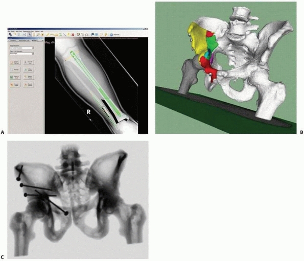
compared with traditional analog templating and measuring techniques.4,35 Figure 17-1A shows a screen shot of a preoperative planning session for internal fixation of a fractured tibia.
measurements and spatial visualization of complex structures and
fractures. It allows the construction of computer models, such as bone surface mesh,
anatomic axes, and osteotomy planes. Bone fragment models and implants
can be visualized in three dimensions and manipulated to analyze
several possible scenarios. The resulting fixation can be evaluated in
three dimensions and with a simulated postoperative radiograph, known
as a digitally reconstructed radiograph, obtained from the preoperative
CT and the fixation hardware. Figures 17-1B-C illustrate the concepts of preoperative planning of reduction and fixation of a pelvic fracture.
developed enabling the performance of virtually all steps of the real
surgical procedure.3,6
This ability to exercise a virtual surgical procedure marks out safe
zones; allows for precise planning of screw dimensions and pathways;
and enables prechecking of the percutaneous option as an alternative to
the open approach.
provide precise, real-time visual feedback of the spatial location of
surgical instruments and anatomic structures that cannot be directly
observed. In current practice, this information is obtained by repeated
use of fluoroscopic radiography, which produces a time-frozen
two-dimensional (2D) view, is not updated in real time, and results in
cumulative radiation to the surgeon, staff, and patient. The goal of guidance is to indicate to the surgeon in real time, via images, graphics, or sound, the best course of action during surgery.
instruments with respect to images of the anatomy using either
preoperative CT or intraoperative fluoroscopic radiography images and
continuously update the image as the instruments and bone structures
move. The resulting display, called navigation images, is equivalent to continuous intraoperative imaging without radiation.
 |
|
FIGURE 17-1 Preoperative planning. A.
Preplanning for internal fixation of a distal tibia and fibula fracture using an intramedullary nail and fibular plate. Interlocking screw sizes are estimated, using a ruler tool. B. Preplanning for reduction and fixation of an acetabular fracture: three-dimensional visualization of the pelvis and fragment (each fragment is indicated in a different color) with planned fixation screws; (C) Simulated postoperative radiography image. (A, Image from TraumaCad, courtesy OrtoCRAT Ltd., Israel. B, C, Images property of the authors.) |
Tracking determines in real time the location of moving objects in
space. Registration establishes a common reference frame between the
moving objects and the images. Visualization creates navigation images
showing the location of moving objects with respect to the anatomy.
Validation ensures that the updated images match the clinical
intraoperative situation.
need for repeated fluoroscopic radiography. However, it requires
additional procedures, including setting up the navigation system and
attaching trackers to both instruments and bone structures of interest,
as well as additional surgical training.
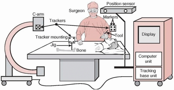
The position sensor determines the spatial location of the trackers at
any given moment in time. By attaching trackers to surgical tools and
bone structures, their relative spatial position can continuously be
followed and updated in the computer display. Trackers are rigidly
mounted on tools and bones with tracker mounting jigs,
which are mechanical jigs similar to screws and clamps. Because the
trackers and their mounting jigs come in contact with the patient, they
must be sterilized. The position sensor is either mounted on the cart,
part of a separate unit, or attached to the ceiling or to a wall. It is
aimed at the surgical field so that the expected tracker motions are
within its working area throughout surgery. The position sensor’s
location can be changed during surgery as needed. When fluoroscopic
radiography images are used for navigation, the computer unit is also
connected to a C-arm and imports images acquired with it. The C-arm is
usually fitted with its own tracker to determine its relative location
with respect to the tracked objects and imaged anatomy.
signals from the position sensor and the trackers. The computer
integrates the signals from the base unit with fluoroscopic radiography
or
CT images and instrument models (registration), and creates one or more
views for display (visualization). The navigated images are updated in
real time by the computer as the instruments and anatomy move. The tool calibration unit
is used to obtain geometric data of surgical tools fitted with
trackers, such as the tool tip’s offset. These geometric data are used
to create the instrument model for display.
 |
|
FIGURE 17-2
Equipment setup in the operating room. A navigation system consists of a computer unit, tracker unit, and tracker mounting hardware. The computer unit consists of a computer, keyboard, mouse, and display monitor or touch screen. The tracking unit consists of a tracking base unit, position sensor, one or more trackers, and a tool calibration unit (optional). (Image property of authors.) |
 |
|
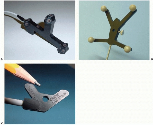
FIGURE 17-3 Trackers. A. Active optical tracker. B. Passive optical tracker. C. Magnetic tracker. (Courtesy of Traxtal Technologies, Toronto, Canada.)
|
of trackers by measuring spatially dependent physical properties, which
can be optical, magnetic, acoustic, or mechanical. Currently, two types
of tracking technologies are available for medical applications:
optical and magnetic, with optical being by far the most commonly used (Fig. 17-3).
Each camera measures the distance of the markers from the camera.
Because the base distance between the optical cameras is known, the
position of the marker with respect to the camera’s base line can be
computed by a method known as triangulation. A tracker consists of three or more markers mounted on a rigid base (Fig. 17-3A).
The tracker’s position and orientation are determined by the markers’
positions relative to each other and by their sensed position with
respect to the position sensor. A key requirement is the maintenance of
an unobstructed line-of–sight between the position sensor and the trackers. Optical tracking systems can be active, passive, or hybrid.
which are light-emitting diodes (LEDs) that are strobbed (turned on and
off) in tandem by the base unit. LEDs emit infrared light that is
detected by the cameras. The cameras’ capture is synchronized with the
LED strobbing so that the identity of the lighting marker is known.
Active trackers consist of three or more wired LEDs mounted onto a
rigid base and connected by a cable or by a wireless link (tetherless
communication) to the tracking base unit. Each active tracker has a
unique identifier. Active trackers are built so that they can be
sterilized many times.
Reflective spheres reflect the infrared light generated by the position
sensor, which is then detected by the cameras. Unlike the active
markers, passive markers are not controlled by the tracking base unit
and are “seen” simultaneously by the cameras. Passive trackers consist
of three or more passive markers. The identity of the passive tracker
is determined by the configuration of the markers on the rigid mounting
base. Consequently, no two passive trackers can have the same marker
configuration. The tracking base unit must know the tracker
configuration. Because the markers lose their reflectance with
sterilization and touch, they must be replaced after several uses.
|
TABLE 17-1 Comparison of Tracking Technologies
|
||||||||||||||||||||||||||||||||||||||||||||||||||||||||||||||||||||||||||||||||||||||||||||||||||||
|---|---|---|---|---|---|---|---|---|---|---|---|---|---|---|---|---|---|---|---|---|---|---|---|---|---|---|---|---|---|---|---|---|---|---|---|---|---|---|---|---|---|---|---|---|---|---|---|---|---|---|---|---|---|---|---|---|---|---|---|---|---|---|---|---|---|---|---|---|---|---|---|---|---|---|---|---|---|---|---|---|---|---|---|---|---|---|---|---|---|---|---|---|---|---|---|---|---|---|---|---|
|
||||||||||||||||||||||||||||||||||||||||||||||||||||||||||||||||||||||||||||||||||||||||||||||||||||
active and passive tracking. Hybrid tracking systems simultaneously
track both passive and active trackers, thus providing the advantages
of both technologies. Table 17-1 summarizes
the advantages and disadvantages of active (wired and tetherless) and
passive trackers. Because neither technology is always superior to the
other in all categories, the anatomy, the surgical instruments, and the
clinical situation determine the best choice of trackers.
comparable. Passive trackers are lightest, while tetherless active
trackers are heaviest because of the battery required to activate the
circuitry and the LEDs. Passive trackers are more rugged than active
ones because they have no electronics. Tetherless trackers are more
convenient because there are no cables to get in the way. In terms of
functionality, active trackers have the advantage that they indicate,
on the tracker itself (via a light indicator), when the line-of-sight
is maintained, while passive tracker obstruction can only be shown on
the display. Active trackers are automatically recognized as soon as
they are plugged in. Passive trackers
are
the most reliable, because there are no electric connections;
tetherless active trackers are the least reliable because of possible
communication interferences and their short battery life (LEDs require
substantial power for illumination). In terms of performance, active
trackers are somewhat more accurate than passive trackers but they are
also more sensitive to their orientation with respect to the cameras.
In terms of cost, it is highest for active tetherless tracking because
of the additional electronics and lowest for passive trackers, which
have no electronics at all. The running cost of active wired tracking
is lowest, because there are no batteries or reflective spheres to
replace. The amortized cost over time of the wired active trackers
represents a significant improvement.
variations of generated magnetic fields. The position sensor consists
of a magnet that generates a uniform magnetic field and a sensor that
measures its phase and intensity variations. Trackers consist of one or
more miniature coils mounted on a rigid base that generate a local
magnetic field from an electric current, either alternating or pulsed
direct (Fig. 17-3C). Both the position sensor
and the trackers are connected to the tracking base unit. The tracker
magnetic field modifies the sensor’s magnetic field characteristics
according to its position in space. The location of the tracker is
computed from the relative variations of the sensor’s intensity and its
phase magnetic field. A key requirement is the maintenance of a uniform
magnetic field, which is altered by the vicinity of magnetic fields
from other electronic devices and by nearby ferromagnetic objects.
cheaper than optical trackers and their functionality is similar to
that of active optical trackers (Table 17-1).
However, the accuracy of existing magnetic tracking systems is less
than that of optical tracking systems. Their main advantages are that
they are small and do not require a direct line-of-sight, and therefore
they are useful in percutaneous procedures. However, they do require
careful control of the environment in which they operate, because the
nearby presence of ferrous objects and electrical instruments in the
operating room can influence their measurements.
A 3D measurement instrument provides a stream of spatial location
measurements in a given range, accuracy, and rate (frequency). It
measures the location of an object (a
tracker) with respect to a fixed coordinate frame centered at the
position sensor’s origin. The location of an object in space, its
position and orientation, is uniquely determined by six parameters:
three translational (vertical, horizontal, and depth) and three
rotational (roll, yaw, and pitch).
Its shape is usually simple, such as a sphere, pyramid, or cube,
depending on the type of position sensor technology used. The distance
between the position sensor and the tracking work volume center is
fixed.
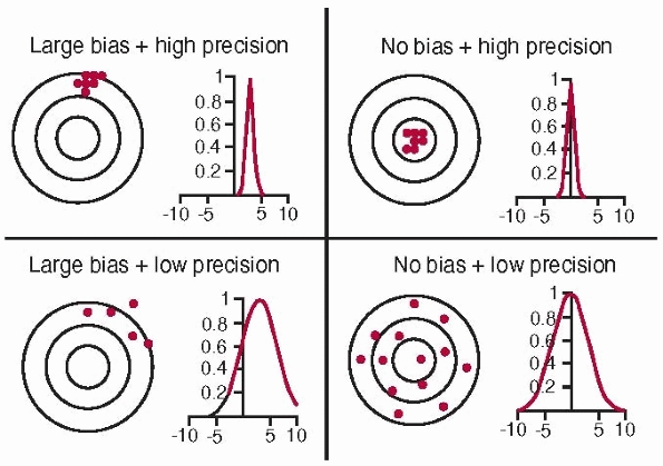
Bias is a measure of how closely the mean value in a series of
replicated measurements approaches the true value. Precision is a
measure of how closely the values within a series of replicated
measurements agree with each other. It has no units and indicates the
relative degree of repeatability. Repeatability is a measure of resolution and stability.
Resolution is the smallest discernible difference between two
measurements. Stability refers to making identical measurements at a
steady state and over a sufficiently long period. Frequency
is the number of overall measurements per second. Static accuracy
refers to measurements obtained when the trackers are at rest, while
dynamic accuracy refers to measurements obtained as the trackers move.
 |
|
FIGURE 17-4
Accuracy and bias. Accuracy is a combination of precision and bias. High accuracy requires no bias and high precision (top right). The concentric circles represent the distance from the true value (the common center of the circles); dots represent actual measurements. (Image property of authors.) |
-
Position sensor accuracy:
For optical tracking, the number of cameras, the distance between them,
and their resolution. For magnetic tracking, the intensity of the
magnetic field and the resolution of the magnetic sensor. -
Marker accuracy:
For optical tracking, the type of LEDs or sphere size and reflectance.
For magnetic tracking, the strength of the coil magnetic field. -
Tracker accuracy: Depends on the marker accuracy, number of markers, their configuration, and the distance between them.
-
Tracking system accuracy: Depends on all of the above, and on the relative position and orientation of the position sensor with respect to the trackers.
the tracking work volume. It is usually highest at the center, with
decay toward the boundaries of the tracking work volume. Therefore, the
position sensor should always be placed as close as possible to the
center of the expected operating volume. It is often useful to
distinguish between position and orientation accuracy. Statistics on
accuracy include average, minimum, maximum, and root-mean-square (RMS)
error. Table 17-2 summarizes the typical characteristics of current tracking systems.
(Fig. 17-5).
To track a surgical tool, a tracker can be added to it or the tool can
be custom designed, with markers integrated within the tool. To track
the C-arm, a ring with several dozen markers is attached to its image
intensifier. It is very important that the trackers do not move with
respect to the tracked body during surgery, because relative movement
cannot be detected and measured and will increase system error.
|
TABLE 17-2 Typical Characteristics of Commercial Tracking Systems
|
||||||||||||||||||||||||||||||||||||||||
|---|---|---|---|---|---|---|---|---|---|---|---|---|---|---|---|---|---|---|---|---|---|---|---|---|---|---|---|---|---|---|---|---|---|---|---|---|---|---|---|---|
|
||||||||||||||||||||||||||||||||||||||||
reference frame between objects and images. It is a prerequisite for
creating a reliable image of the intraoperative situation, accurately
showing the relative locations of the anatomy and the surgical tools of
interest with respect to the preoperative and/or intraoperative images.13 Registration is achieved by transformations between the objects’ coordinate frames at all times.
coordinate frame serves as a reference within which the spatial
locations (position and orientation) of objects can be described. Each
object of interest has its own coordinate frame. The relative location
of objects is described by a transformation
 , describing the location of B‘s coordinate frame with respect to A.
A transformation is a matrix describing the relationship between the
three rotational and three translational parameters of the objects. The
transformation is static (constant) when the relative locations of A and B do not change or dynamic
 (a function of time t) when one or both of the objects move. The relative locations of objects are obtained by chaining (composing) transformations. Thus, the location of C with respect to A is obtained from the location of B with respect to A and the location of C with respect to B,
 , as illustrated in Figure 17-6.
This registration involves four types of transformations: (1) tracker
transformations, (2) tool transformations, (3) image transformations,
and (4) display transformations.
-
Tracking transformations: Tracking transformations
![image]()
indicate the location of each tracker with respect to the position
sensor coordinate system. They are provided in real time by the
tracking system and can be static or dynamic, depending on whether the
objects attached to the tracker move or do not move. The relative
location of one tracker with respect to the other is obtained by
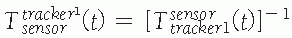
chaining their transformations: where
where![image]() is the inverse transformation.
is the inverse transformation. -
Tool transformations: Tool transformations
![image]()
indicate the location of the tool coordinate frame with respect to the
tracker. Because the tracker is rigidly attached to the tool, the
transformations are static. They are provided at shipping time when the
tracker and the tool come from the same manufacturer (i.e.,
precalibrated tools). Alternatively, they are computed shortly before
surgery with a tool calibration procedure,
which typically consists of attaching the tool to a tracked calibration
object and computing with custom calibration software the
transformation and the tool’s geometric features, such as its main axis
and tip position. -
Image transformations: Image transformations
![image]() indicate the location of the images with respect to the position sensor. There are two types of transformations,
indicate the location of the images with respect to the position sensor. There are two types of transformations, ![image]() and
and ![image]() ,
,
depending on the type of images used: one preoperative CT or several
intraoperative fluoroscopic radiography images. The transformation
between the position sensor and the CT image![image]() is static and unknown and must be computed with a CT registration procedure. The transformation between the position sensor and fluoroscopic radiography images
is static and unknown and must be computed with a CT registration procedure. The transformation between the position sensor and fluoroscopic radiography images ![image]() , where i indicates each C-arm viewpoint, is computed from the transformation
, where i indicates each C-arm viewpoint, is computed from the transformation ![image]() of the ring tracker attached to the C-arm image intensifier transformation and
of the ring tracker attached to the C-arm image intensifier transformation and ![image]() the C-arm internal imaging transformation:
the C-arm internal imaging transformation: In older fluoroscopic units, this internal
transformation is orientation dependent and thus must be computed for
each C-arm viewpoint i.31 -
Display transformations: Display transformations
![image]() and
and ![image]()
indicate the location of the CT and fluoroscopic radiography images
with respect to the display shown to the surgeon, respectively. The
transformations are determined by the viewpoint shown to the surgeon.
Note that the transformation
P.471between the bone and the tracker
![image]() and
and
cannot be computed, because the exact location of the tracker mounting
jig with respect to the bone is not known. Instead, the relative
location of the tool with respect to the tracker is used: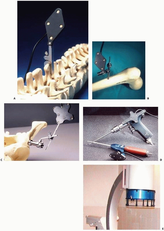 FIGURE 17-5 Trackers and mounting hardware. A. Bone clamp attached to spinous process. B. Bone screw attached to femur. C. Bone screw and extender attached to pelvis. D. Trackers on surgical drill and screwdriver. E. Ring tracker on C-arm image intensifier. (Photographs A,B,D courtesy of Traxtal Technologies, Toronto, Canada; C, courtesy of MedVision, Unna, Germany; E, property of authors.)P.472
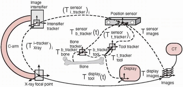
![]() FIGURE 17-6
FIGURE 17-6
Coordinate frames and transformations between objects. The goal is to
compute the location of the surgical tools with respect to the
displayed images T display tool . (Image property of authors.) In effect, the bone tracker becomes the reference coordinate frame and therefore is also called the dynamic reference frame.The registration between the tool coordinate frame and the display coordinate frame
![image]() is computed by chaining the transformations:
is computed by chaining the transformations: For fluoroscopic radiography images, there is one transformation
![image]() and
and ![image]() for every C-arm viewpoint i.
for every C-arm viewpoint i.


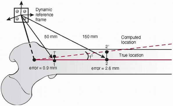
depends on the accuracy of each transformation and on the cumulative
effect of transformation chaining. Because the transformation includes
rotation, the translational error is amplified as the distance from the
reference frame increases (Fig. 17-7).
 |
|
FIGURE 17-7
Influence of the angular error on the translational offset. A dynamic reference frame is attached to the proximal femur. With an angular transformation error of only 1 degree, a nearby target (1) 50 mm from the origin of the bone coordinate frame will be offset by 0.9 mm (1′), which is acceptable in most situations. However, a farther target (2) 150 mm away will be offset by 2.6 mm (2′), which may not be acceptable. (Image property of authors.) |
of the tracking system and on the location of the tracker with respect
to the center of the position sensor working volume. Tool
transformation accuracy depends on the accuracy of the tool calibration
procedure and on the relative location of the tracker with respect to
the tool tip. Image transformation accuracy depends on the accuracy of
the imaging modality used and on the tracking system’s accuracy. For CT
images, it depends on the resolution (slice spacing and pixel size) of
the CT scan and on the accuracy of the CT registration procedure. For
fluoroscopic radiography images, it depends on the C-arm calibration
and on distortion correction procedures. Display transformation
accuracy is very high, as it only involves numerical computations.
bone tracker with respect to the bone will introduce an error in the
registration. It is therefore essential that the bone tracker remain
rigidly secured to the bone at all times during navigation.
images are created by merging the preoperative and intraoperative
images with the tools and bone location information. The navigation
images can be augmented with relevant proceduredependent data, such as
anteversion angle and distance from a predefined safe zone.
preoperative and intraoperative images that are used, on the surgical
tools, and on the surgical procedure. In fluoroscopic-based navigation
systems, the navigation images consist of fluoroscopic radiography
images from the C-arm typically used in conventional surgical procedure
poses (anterior-posterior, lateral, oblique) with the surgical tool
silhouette at its present location superimposed onto them. For example,
when the tool is a long cylinder (e.g., drill, pointer, or
screwdriver), the tool’s location and its prolongation are displayed in
two different colors, to indicate what would be the tool’s location if
the current direction were followed. The number of images, tool
silhouette, and additional navigation information are procedure
dependent.
typically consist of sagittal, coronal, and transverse CT cross
sections, and a spatial view with the preoperative plan (e.g., fixation
screws, fixation plate at their desired location), with the surgical
tool’s silhouette at its current location superimposed onto them.
Typically, the tool tip corresponds to the crosshair location in the CT
cross sections.
various image processing, viewpoint selection, and information display
features such as contrast enhancement, viewpoint rotation and
translation, window selection, and tool silhouette thickness and color
control.
data used for intraoperative navigation closely correspond to the
clinical situation. It is essential to verify and quantify the
correlation; otherwise the data can mislead the surgeon and yield
unwanted results. Validation is an integral part of the navigation
surgical protocol. It is performed both before the surgery starts and
at key points during the surgery.
-
Tool calibration verification:
Verifies that the tool’s geometric information is accurate. Sources of
inaccuracy include deformations in the tool as a result of
high-temperature sterilization, bending, wear and tear, tracker
relative motion, and marker drift. -
Dynamic reference frame verification: Verifies that the bone tracker has not moved with respect to the bone to which it is attached.
-
Registration accuracy verification:
Verifies that the tool, implant, and bone fragment locations are indeed
where they are shown in the navigation images. Over time, registration
accuracy depends on variations in the tool’s calibration accuracy; on
the dynamic reference frame’s relative location with respect to the
bone to which it is attached; on the tracking system’s drift over time;
and on the accumulation of small computational numerical errors.
the navigated surgical tools, and the images used. Tool calibration
verification usually consists of verifying with a calibration jig that
the tool tip is at its computed location. Dynamic reference frame and
registration accuracy verification usually consist of verifying that
the tracked bones and tools are indeed where the navigated images
indicate. This is done by acquiring one or more fluoroscopic
radiography images and comparing them with the navigation images.
Alternatively, it is done by touching with the tip of a surgical tool
the known anatomic landmarks and verifying that the tool tip appears
close to the landmark in the navigated image. Registration accuracy is
quantified by measuring the drift between the actual and the computed
location of tools and anatomic landmarks. When registration accuracy is
inadequate, the surgeon must repeat the registration process.
CAS in skeletal trauma: fluoroscopy-based and CT-based navigation
systems.
superimposing the surgical tool silhouette onto conventional
fluoroscopic images and updating its location in real time, thereby
creating the impression of continuous fluoroscopy without the ensuing
radiation. The resulting effect is called virtual fluoroscopy.
Fluoroscopy-based systems are thus closest to the current practice of
conventional fluoroscopy because the navigation images are in close
proximity to the familiar fluoroscopic images, with the advantage being
that only a dozen fluoroscopic radiography images are used, instead of
tens or even hundreds.
systems: systems that use conventional C-arm fluoroscopy and those that
use new 3D fluoroscopy, such as the Siemens Iso-C 3D C-arm. Virtually
any C-arm can be used, provided that the images are corrected for
geometric distortion and the C-arm imaging properties are calibrated.
The correction is usually done with an online C-arm calibration
procedure that relies on imaged patterns of metallic spheres mounted on
the C-arm ring tracker (the spheres appear as a grid of black circles
in the images). Newer conventional and 3D C-arms do not require
calibration.
surgery, the rolling cart with the display, computer unit, and tracking
base unit is positioned in the operating room so that the display can
be easily seen by the surgeon. The position sensor is positioned so
that it does not get in the way and its working volume is roughly at
the center of where the surgical actions will take place. Next, the
ring tracker is mounted on the C-arm’s image intensifier and covered
with a transparent plastic for sterility. The patient is then brought
into the operating room and surgical preparations proceed as usual.
Next, the surgeon validates the tool calibration and installs the
dynamic reference frame with tracker mounting hardware. Touching known
anatomic landmarks with the tip of a surgical tool and verifying that
the tool tip appears close to the landmark in the navigated image
validates the registration. Once registration validation is successful,
the navigated surgery begins. At key points during surgery, such
as
before drilling a pilot hole or inserting a fixation screw, one or more
validation fluoroscopic radiography images can be taken to verify that
the navigated images correspond to the actual situation. The navigation
procedure can be repeated with other tools and implants. At any time
during the procedure, the navigation system can be stopped and the
procedure can continue in a conventional manner.
that allows for the acquisition of CT-like images during surgery by
taking about 100 fluoroscopic radiography images at 1-degree intervals
with a motorized isocentric C-arm. It can also be used as a
conventional C-arm, with the added advantage that CT and fluoroscopic
radiography images acquired with it are already registered. Although
these images are not of as high a quality as those obtained with a
preoperative CT, and can be used only to image limbs, the radiation
dose is about half of the dose of a regular CT and accurately reflects
the actual intraoperative situation. The navigation images consist of
both CT images and fluoroscopic radiography images. The advantages are
that complex fractures can be better visualized and that CT images can
be taken before and after reduction. In addition, CT images present an
entrée for better intraoperative planning and thus might advantageously
blur the distinction between preoperative and intraoperative planning.
The surgical protocol is very similar to that of conventional
fluoroscopy, with the additional step of acquiring the intraoperative
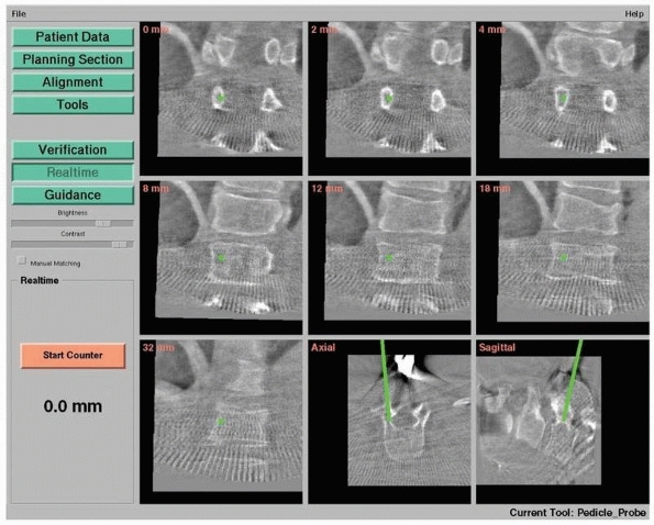
CT images during surgery when necessary.9,12 Figure 17-8 shows an example of navigation with 3D fluoroscopy.
superimposing the surgical tool silhouette onto preoperative CT
cross-sectional and spatial images and updating its location in real
time. This type of navigation is only feasible when a CT data set is
available.
few hours to a day before surgery, a CT scan is acquired and
transferred to the computer, within which the planning will be
performed by the surgeon. With the help of preoperative planning and
model construction software, the surgeon visualizes the clinical
situation, takes measurements, and plans the target location of
implants and fixation screws for navigation. The plan is then saved for
use during surgery. Shortly before surgery, the rolling cart with the
display, computer unit, and tracking base unit is positioned in the
operating room so that the surgeon can easily see the display. The
position sensor is positioned so that it does not get in the way and
its working area is roughly placed at the center of where the surgical
actions will take place. The preoperative plan is loaded into the
computer unit. The patient is then brought into the operating room and
surgical preparations proceed as usual. Next, the surgeon validates the
tool calibration and installs the dynamic reference frame with tracker
mounting hardware. Prior to the beginning of surgery, the preoperative
CT is registered to the actual intraoperative anatomic site with a CT registration procedure.
Touching known anatomic landmarks with the tip of a surgical tool and
verifying that the tool tip appears close to the landmark in the
navigated image validate the registration. Once registration validation
is successful, the navigated surgery begins. At key points during
surgery, such as before drilling a pilot hole or inserting a fixation
screw, one or more validation fluoroscopic radiography images are taken
to verify that the navigated images correspond to the actual situation.
The navigation procedure can be repeated with other tools and implants.
At any time during the procedure, the navigation system can be stopped
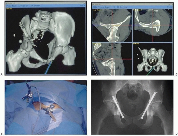
and the procedure can continue in a conventional manner. Figure 17-9 shows images of a typical CT-based navigation system.22,23
 |
|
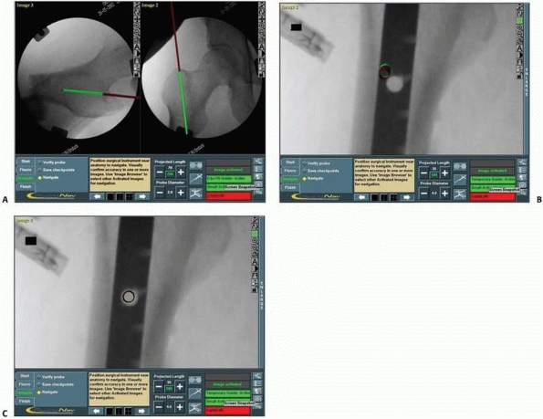
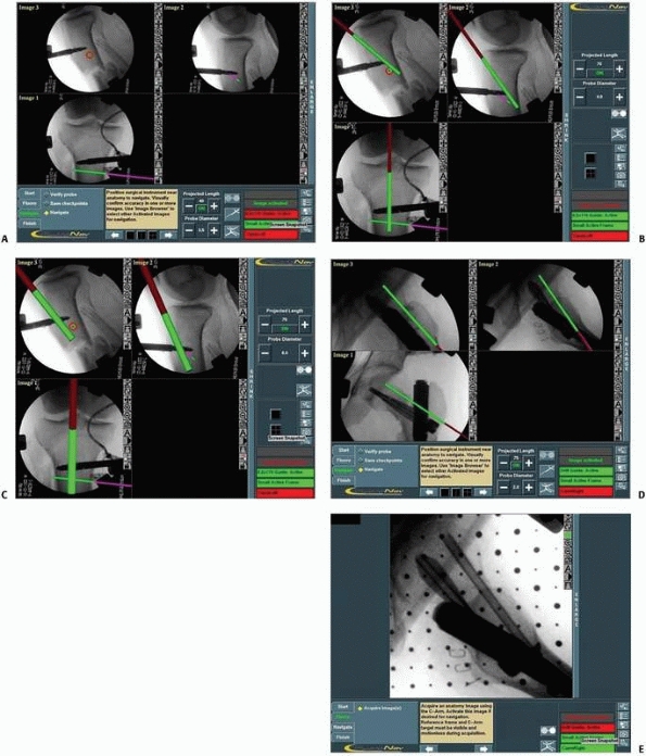
FIGURE 17-8
Pedicle screw insertion with three-dimensional fluoroscopy. Screen view of three-dimensional fluoroscopy navigation during pedicle screw insertion in a fractured thoracic vertebra with the SireMobil Iso-C 3D (Siemens Medical Solutions, Erlangen, Germany). (Image courtesy of Prof. F. Gebhard.) |
procedure. The relationship between the CT and the intraoperative
situation is established by automatically matching a set of points on
the surface of the bone region to the corresponding points on the CT
surface model. The intraoperative point set is obtained by touching the
surface of the bone region of interest with a precalibrated tracked
pointer and recording the location of a few dozen of these points by
pressing on a foot pedal. The point set is then matched to a
corresponding point set, automatically extracted from the CT surface
model of the same bone region. The points must be a representative
sample of the bone surface; that is, they must be as far apart as is
possible and cover the entire region of interest.
advantages and disadvantages of navigation systems. Only CT-based
systems allow for preoperative planning. Spatial visualization is only
available with a CT data set and thus is only available in CT-based and
3D fluoroscopy-based systems. No additional registration procedure is
necessary for intraoperative imaging, as the position sensor provides a
common reference frame for trackers and images. All navigation systems
require additional setup procedures, which is a drawback compared with
conventional practice. CT-based systems are not suitable for fracture
reduction, as there is no way to determine bone fragment locations
during and after reduction. The 3D fluoroscopy-based systems can be
used before and after, but not during, reduction, provided that two
before
and
after images are acquired. In fluoroscopy-based systems, reduction
navigation is feasible when the bone fragments have trackers attached
to them and new images are acquired at key points during reduction.
Currently, CT-based navigation requires the surgeon to touch the
surface of the bone; therefore, it cannot be used for percutaneous
procedures. In terms of radiation, the best option for the patient and
the surgeon is fluoroscopy-based navigation. The indications for
fluoroscopy-based systems present the most options, while 3D
fluoroscopy-based and CT-based systems are best used with complex
situations requiring spatial visualization. Currently, CT-based systems
are mostly used for pelvic fracture fixation, while fluoroscopy-based
systems are used for intramedullary nailing and fixation screw
insertion.
 |
|
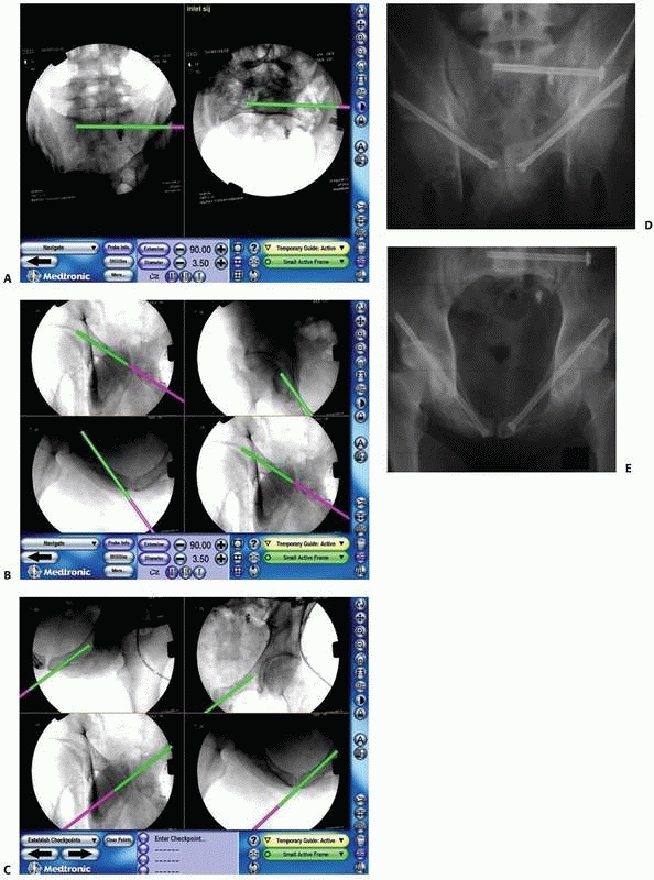
FIGURE 17-9 Retrograde anterior column screw. A.
Three-dimensional model of the patient’s pelvis built on the computer-guided surgery workstation (StealthStation; Sofamor-Danek, Memphis, TN). The position of a virtual drill guide for placement of a retrograde anterior column screw has been added to the virtual image. B. Intraoperative photograph taken during placement of the right retrograde anterior column screw (view from the foot of the bed). The reference frame attached to the external fixator is visible at the top left. Also visible are the navigated drill guide, chuck, and guidewire. C. The two top images show a preoperative plan for placement of the left-sided retrograde anterior column screw. Two customized orthogonal planes relative to the drilling path are depicted, with a planned trajectory diameter of 7.0 mm. There is a small safe zone available between the planned position of the implant and the pelvic brim, as well as the articular surface of the acetabulum. The implant path is perpendicular to the fracture line, allowing lag screw reduction and fracture fixation. D. Anteroposterior pelvis image at 6 weeks postfixation shows accurate implant placement and early fracture healing without displacement. (Images courtesy of Dr. D. Kahler.) |
the treatment of trauma patients should take into account available
innovative technologies together with the clinical situation, as part
of the decision-making process. The main goals of CAS are minimal
invasiveness and maximal accuracy in surgical procedures. Recent
experience has shown that, if used appropriately, this combination has
added value. While the first generation of CAS uses computerized
technology for current surgical concepts, it is clear that in the
future the surgeon will be able to develop new ways of approaching
surgical conditions.
are of major concern in trauma management. Damage control principles
are considered the leading guidelines in the treatment of the severely
injured patient. Alternatively, isolated skeletal trauma may be treated
in a semielective fashion. Adding computer-assisted procedures to the
trauma armamentarium is definitely influenced by, and affects,
time-related factors. This is relevant to all stages of trauma
patients’ treatment, beginning with the preplanning stage and up to the
end of the surgery itself.
|
TABLE
17-3 Comparison between the Conventional Technique and Fluoroscopy-Based and Computed Tomography (CT)-Based Navigation Systems |
||||||||||||||||||||||||||||||||||||||||||||||||||||||||||||||||
|---|---|---|---|---|---|---|---|---|---|---|---|---|---|---|---|---|---|---|---|---|---|---|---|---|---|---|---|---|---|---|---|---|---|---|---|---|---|---|---|---|---|---|---|---|---|---|---|---|---|---|---|---|---|---|---|---|---|---|---|---|---|---|---|---|
|
||||||||||||||||||||||||||||||||||||||||||||||||||||||||||||||||
time-consuming and cumbersome procedure. The system’s set-up time and
registration process prolong the preparation phase and might not suit
acute trauma management considerations. Moreover, experienced surgeons
believe that most surgical tasks can be easily, sufficiently, and
accurately carried out, without the use of computer-related
technologies. This conservative approach is well known in medical
history, whenever a new technology emerges. For example, many years
elapsed from the introduction of laparoscopic procedures until surgeons
were ready to routinely use them.
for several years, it appears that we are still in the learning phase
for CAS systems, and therefore indications for their use are still
being selected. Further assimilation of these promising technologies
requires them to become easier to use (i.e., more user friendly). The
set-up time for the computerized system will definitely be reduced in
the modern surgical suite, when it is built directly into the operating
theatre environment, as presently available in several pioneering
institutions. Furthermore, the execution of some surgical tasks is
faster and more accurate with CAS equipment and will, in the future,
allow for procedures that are currently considered almost unfeasible.
For example, the placement of a sacroiliac screw in the fixation of
pelvic and acetabular fractures becomes a fast and accurate procedure
with minimal radiation by using a navigation system.7,8,22
posterior column screw placement, which previously had been considered
an almost impossible task to perform and now is an available option
with computer assistance.32,41
The solutions may be categorized into “enablers” and “improvers.” While
enablers refer to procedures that are not possible without CAS (i.e.,
the introduction of a new concept or ability rather than a translation
of a current technique into CAS), improvers mainly yield improved
accuracy and not a new concept. A simple but extremely important
example of improvement is the significant reduction in radiation
exposure that can be achieved with CAS. As more orthopaedic procedures
are found to be suitable for CAS applications and as younger surgeons,
born into the era of information technologies, enter the operating
theatre, the adoption of CAS will become more natural and routine in
the operating rooms.
trauma care are percutaneous surgical procedures in which added imaging
can provide essential information that will contribute to reducing
invasiveness and increasing accuracy.24,29
Clearly, the fixation of nondisplaced fractures is most suitably
carried out with navigation systems, although often the indication for
internal fixation is questionable. Alternatively, because available
systems can only follow one or two tracked bony fragments, they are not
suitable for treating displaced multiple fragment fractures such as
comminuted articular fractures, where careful anatomic reduction is
required.
or stable situations. For example, using a fracture reduction table or
an external fixator eliminates movement between fragments and creates a
temporary situation in which there is little or no movement at the
fracture site. Moreover, it has been shown that in such “stable”
situations, the reference frame can be attached to the fracture table,
avoiding additional harm to the patient while maintaining acceptable
accuracy.19 Following fracture reduction,
a guidewire or fixation tool can be inserted using the navigation system according to specific clinical guidelines.
to use a CAOS-ST system. For example, the accuracy needed for pedicular
screw insertion is by far greater than that needed for hip fracture
fixation with cannulated screws. Accuracy is directly influenced by the
cost of inaccuracy (e.g., the cost of inaccuracy in spinal surgery is
much greater than in intramedullary nailing).
placement accuracy and reduce variability compared with manual
placement. In a recent study, the accuracy of cannulated screw
placement in hip fracture fixation was evaluated.29
After verifying stable reduction on a fracture table, the reference
tracker was attached to the anterior superior iliac crest. The
reference frame was not attached to the affected bone so as to improve
working convenience during the procedure and minimize morbidity. It was
found that the accuracy of the procedure was much better than that of
nonnavigated procedures. The navigation system enabled the surgeon to
place screws with optimal alignment including configuration,
parallelism, and scattering. This experience demonstrates that stable
reduction creates a stable situation for navigation systems and that
the reference tracked frame may be fixed, on such occasions, to an
adjacent bone as well as to an external fixator or to the operating
table, as mentioned earlier.19
is suitable for CAOS-ST is determined by the surgeon’s knowledge and
capabilities. In most trauma cases, fluoroscopy-based navigation (2D or
3D) is the method of choice.
room to create a surgeon-friendly environment and to enable proper
tracking without interference (Fig. 17-10).
Adding CAOS-ST equipment (computer, monitor, position sensor, and
trackers) to an already crowded room requires careful planning. The
computer screen should be positioned so that the surgeon can see it
without any effort, because, as in arthroscopic procedures, most of the
time the surgeon will watch the screen rather than the operative site.
Easy access to the computer’s control panel is also important and is
usually realized with a sterile touch screen. When using optical
tracking, maintaining an unobstructed line-of-sight between the
position sensor and the trackers is very important. Thus, the location
of the position sensor with respect to the surgeon, nurses, and patient
must be carefully examined.
learning curve. In CAS, the learning curve affects all members of the
surgical team. It affects surgeons performing the operation, nurses
having to cope with new tools, anesthetists who need to adjust the
anesthesia time to the expected operation time, and x-ray technicians
who sometimes need to operate fluoroscopy-based navigation. The entire
team should be aware that there is a “new partner” in the operating
theater (i.e., the computer), and sometimes a computer technician will
also need to be part of the team.
field of vision is determined by the location of the ring tracker
attached to the C-arm, the reference frame tracker attached to the
patient’s anatomy, and by the optical camera. During the navigation
phase, tracked surgical instruments replace the ring tracker and the
tracking space changes accordingly. Continuous tracking of the
patient’s anatomy and of the surgical instrument is required.
Verification and validation are extremely important at every stage, to
achieve optimal accuracy. Tracking the surgical instrument is more
simple and precise, whereas tracking anatomy, especially in trauma
surgery, is more problematic, such as in those cases where two
fragments are simultaneously tracked, as in the fracture reduction
process.
usually the main cause of inaccuracy. The first obstacle is attaching
the rigid frame to the patient. The problem of inserting a stable screw
into the bone fragment is well known from the use of external fixation.
Screw or pin grip depends on their design and on bone quality. For each
procedure, the location needs to be selected according to local
morbidity (soft tissue access and crucial anatomic structures),
convenience during the procedure (line-of-sight and free surgical
site), and stability of anatomic frame fixation. The stability of the
screw holding the anatomically referenced tracked frames depends on
bone quality and soft tissue interference. Subcutaneous locations such
as the iliac crest or the medial aspect of the tibia are preferable.
The site of frame fixation should also take into account the surgical
task (e.g., avoiding the medullary canal in long bone fracture
reduction).
well as several soft tissue adaptors and are able to detach from the
frame during the nonnavigational steps of the procedure. Improvement of
bone tracking technology, as well as the ability to track more than one
or two large bone fragments, will significantly enhance the surgeon’s
surgical performance in the treatment of fractures.
is recommended are now presented. For each clinical application, both
the rationale and the contribution of these systems will be discussed.
The aim of this section is to expose the reader to the first
generations of computerized navigation systems. The specific indication
for each surgical procedure is beyond the scope of this discussion. All
the surgical procedures discussed are based on optical infrared
tracking.
is to mount the ring tracker on the C-arm and drape it for sterility.
Next, a reference frame (either one or two) is attached to the
patient’s anatomy and several essential fluoroscopic images are
acquired—typically, between one and four for 2D navigation or
computerized controlled imaging for 3D navigation using Iso-C
technology. The optimal images are stored in the computer and activated
during the navigation process. It should be noted, that for all of the
clinical examples to be discussed, the preliminary fluoroscopic views
can be taken while the operating team stands at a distance of 2 m or
more from the radiation source, thus almost eliminating the team’s
radiation exposure.
designated surgical tool (i.e., wires, awls, drill-bits, etc.), which
is to be attached to a tracker, commonly referred to as the instrument tracker. The contour of the instrument in its current location is displayed on the previously activated fluoroscopic images,
thereby creating the effect of virtual fluoroscopy. Similar concepts
may be used for tracking fracture reduction—in this case, instead of
following the relationship between the tracked instrument and the
tracked bone, we track the relationship between the two tracked bone
fragments (Fig. 17-11).
 |
|
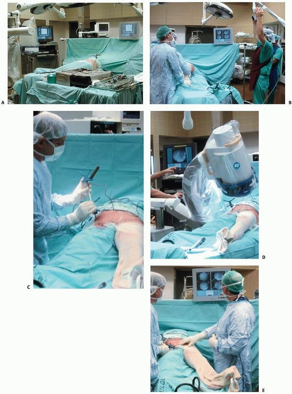
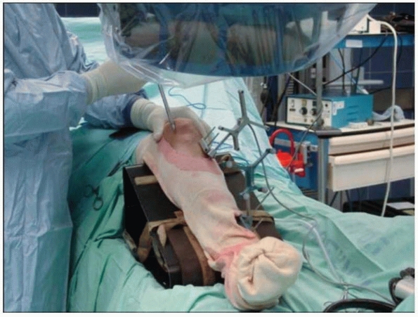
FIGURE 17-10 Operating room setup. A. View of the operating room showing locations of the computer unit, position sensor, and bone-mounted reference frame. B. Reorientation of the position sensor during surgery. C. Surgical tool calibration. D. Acquisition of fluoroscopic images. E. Navigation with fluoroscopy-based system. (Images property of authors.)
|
 |
|
FIGURE 17-11
Tibial intramedullary nailing using fracture reduction software with two frames attached to the two bone fragments. (Image property of authors.) |
-
Trajectory navigation—drill guide applications (hip and pelvic fractures)
-
Fracture reduction
-
Intra-articular fracture fixation
-
Novel uses of navigation: localization of bone lesions or removal of surgical hardware and shrapnel
nails and screws is a common task in orthopaedic traumatology. This
procedure can often be performed percutaneously and thereby fit the CAS
philosophy of minimal invasiveness with high accuracy. Navigated 2D
fluoroscopy provides a natural computerized enhancement for this
surgical application. Thus, the most common current indication for the
use of CAOS-ST systems is the insertion of cannulated screws. This
surgical procedure requires high accuracy and unusually large radiation
exposure for the surgeon and for the patient. Both issues can be
successfully addressed with fluoroscopy-based navigation.
internal fixation of slipped capital femoral epiphysis are procedures
that can greatly benefit from computerized navigation. The use of
computerized navigation turns the procedure into a simple task to
perform, while using minimal radiation.24
Internal fixation of intracapsular fractures of the femoral neck is
considered straightforward, although accurate performance requires high
proficiency on the one hand and large exposure to radiation on the
other. Recently, a prospective comparison between patients who
underwent internal fixation of intracapsular fracture of the femoral
neck by means of cannulated screws, with and without the assistance of
a navigation system, was performed.29
This study revealed that computerized navigation increased the accuracy
of screw placements in all measured parameters. Having acquired
proficiency with the computerized system, the surgeon is ready to move
on to the next level, which includes percutaneous fixation of pelvic
and acetabular fractures.
for the orthopaedic trauma surgeon. The pelvis is a complex 3D
structure that contains important anatomic structures in a confined
environment. Therefore, surgical fixation of displaced traumatic
fractures should be meticulously performed under strict visual control,
because the “safe zones” are narrow. In many cases, closed reduction
and percutaneous fixation is feasible and provides enough stability to
allow for immediate patient mobilization. The conventional image
intensifier is most frequently used in percutaneous pelvic fixation.
However, it provides only a 2D image and requires multiple images in
different projections to determine the correct point of entry and the
direction of the screw. Furthermore, the use of conventional
fluoroscopy makes the procedure long and tedious and exposes both the
patient and the medical team to prolonged radiation.8,22,23
Fluoroscopy-based navigation systems (2D and 3D) have the potential to
significantly reduce radiation exposure and operative time, while
allowing the surgeon to achieve maximum accuracy.8,29,38,46
surgery are controversial and are not discussed here. At this stage, a
selected population with traumatic pelvic and acetabular fractures can
be treated percutaneously under three conditions: (i) cases with
minimally displaced pelvic and acetabular fractures, (ii) displaced
fractures with feasible closed reduction, and (iii) in cases of open
pelvic surgery when the insertion of several screws is very challenging
and demands the assistance of guiding systems such as fluoroscopy or
navigated fluoroscopy following appropriate open reduction.
to fracture fixation of the pelvis is still evolving and is undergoing
many improvements and developments in which computerized technology may
be of great assistance. For example, in preplanning, the use of
standard axial CT data to create computer-reconstructed 3D images
and/or models may replace the standard radiographic assessment of
pelvic and acetabular fractures.5,11,16,38
Similarly, 3D fluoroscopy technology allows the surgeon to obtain
immediate and accurate 3D reconstructions in the operating room. By
integrating these images into navigation systems, preplanning becomes
easier and more accurate and allows for direct, truly spatial surgical
navigation. It also enables the precise evaluation of closed reduction
(using a fracture table, external fixator and/or other fixation
instruments) before the insertion of the navigated screws.
surgery, the dynamic reference frame can rigidly be attached to the
patient’s iliac crest. Several appropriate fluoroscopic images of the
pelvis are acquired and saved in the system’s computer. No further
fluoroscopic imaging is necessary, except for verification fluoroscopy
prior to the insertion of the cannulated screw, or in the case of
reduced fracture, the crossing of the fracture site.
fluoroscopic images, the surgeon can accurately determine the entry
point and direction of each screw. At the same time, by means of a
virtual trajectory line, the correct length and diameter of the screw
can be calculated (Fig. 17-12). After satisfactory virtual alignment and length have been achieved, the conventional
guidewire pertaining to the cannulated screw system is driven through
the drill guide. Before insertion of a self-drilled cannulated screw,
the position of the guidewire should be verified by fluoroscopy. When
the insertion of several screws in the same area is required, such as
in the fixation of fractures or dislocations in the sacroiliac zone,
the acquired fluoroscopic views can be used for the insertion of more
than one screw (Figs. 17-13 and 17-14).
 |
|
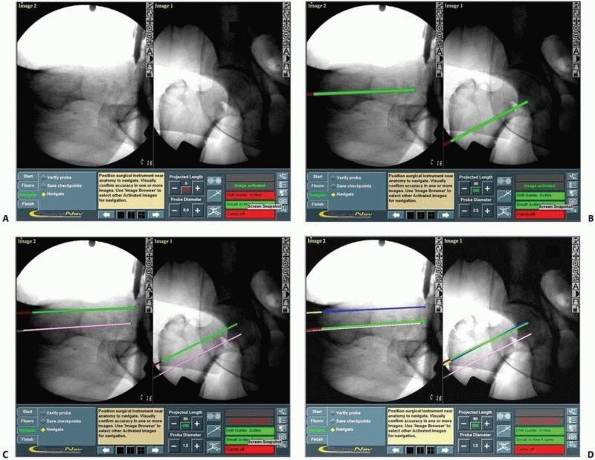
FIGURE 17-12 Cannulated screws. A. Anteroposterior and lateral views of a reduced intracapsular fracture of the femoral neck displayed on the computer’s screen. B-D. Insertion of the three guidewires without additional radiation. (continues)
|
from the surgical procedure and intervention, rather than from the
initial injury. Therefore, it is only natural that percutaneous minimal
surgical approaches are sought, to overcome the difficulties that arise
in relation to fractures in the complex anatomy of the pelvis and
acetabulum.
in many long bone fracture cases. Although it is a routine procedure,
performed by most trauma surgeons, it is not devoid of technical
pitfalls and complications. Achieving accurate and successful results
with conventional techniques involves exposure to significant amounts
of radiation for both patients and the surgical team.
intramedullary nailing by increasing precision, minimizing soft tissue
damage, and significantly decreasing radiation exposure.14,21,25
Several surgical goals can be achieved by using computerized navigation
systems. The insertion of instruments based on real-time information
becomes possible and significantly increases the accuracy of nail
placement. Determining the exact point of entry of the nail is critical
because it is one of the main sources of morbidity in intramedullary
nailing as well as a reason for malalignment. As previously discussed,
computerized navigation systems help to precisely locate the nail entry
point by means of trajectory navigation, thus minimizing soft tissue
dissection. This is particularly helpful in special cases such as with
obese patients where anatomic landmarks are obscured. Working with
several images simultaneously can also decrease unnecessary drill
holes, tissue damage, and cartilage perforation, because all targeting
is done virtually, before the introduction of the actual instrument.
The insertion of locking screws into certain nails can be a potential
hazard for neurovascular
structures.26,40,43
Additional improvement in nailing techniques is achieved by the
facilitation of Poller screw insertion. When precisely placed, better
angular correction of metaphyseal fractures is achieved. The most
important future contribution of the new generation of navigation
technology will be to allow for the tracking and aligning of two
fragments, thus enabling fracture reduction without radiation and
reduction wire insertion and, more important, its ability to provide
the surgeon with information to restore alignment, including length and
rotation.17,26,34
The precision of length measurement may also decrease the rate of
complications associated with nailing such as protrusion of the nail or
screw ends.
 |
|
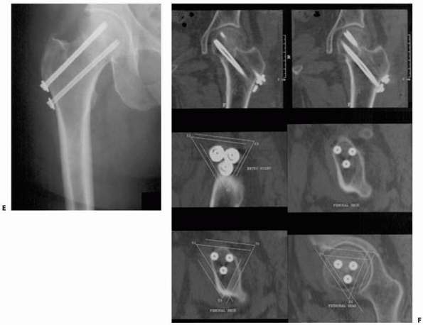
FIGURE 17-12 (Continued) E,F.
Radiograph and CT scan showing the precise scattering of the three screws in a spatial configuration of an inverted triangle. (Images property of authors.) |
surgical navigation system can be implemented, either for the entire
task, at different stages of intramedullary nailing, including the
nail’s entry point, nail and screw measurements, freehand locking, or
placement of auxiliary screws, or for the reduction task. The procedure
will be presented according to its different stages. Navigation of the
entrance point and the locking procedure is performed by using
straight-line trajectory. The reference frame should be attached to the
tracked bone fragment, either proximal or distal, depending on the
specific task.
-
Nail entry point:
The actual point of entry is determined by the use of simultaneous
virtual fluoroscopic views, these usually being anteroposterior (AP)
and lateral views. Before incision, the tracked drill guide is drawn
next to the skin. Its position is adjusted by viewing its virtual
trajectory superimposed on the activated fluoroscopic images so as to
minimize the surgical exposure. The entry point location is
established, while moving the tracked drill guide to an optimal
position (Fig. 17-15A). No further fluoroscopy
is required and a verification fluoroscopic image is taken only after
insertion of the guidewire. After this task is performed, a cannulated
awl or a larger cannulated drill is inserted, according to the
manufacturer’s instructions, through this guide, to open the medullary
canal.26 -
Freehand locking:
This technique is relatively easy to perform and involves minimal
radiation exposure. The bone tracker is fixed closed to the location of
the locking screws. Using the “perfect circle” technique, an AP or a
lateral of the locking hole, in which the holes almost resemble
circles, is acquired. An additional AP or lateral view may be taken to
determine the screw length measurement. The tracked drill guide is then
drawn toward the locking screw area and is navigated until a circle
appears within the hole on the computer screen (Figs. 17-15B-C).
This is followed by drilling through the tracked drill guide and
inserting the locking screw. Sometimes, such as in the case of the
tibial nail, the same AP and lateral views can be used for insertion of
two or even three adjacent locking screws.40,43 -
Placement of other screws:
Poller screws are important tools for correcting bone alignment while
nailing metaphyseal fractures. Precise placement of these screws can
now be performed using a technique similar to that of locking screws.
P.482Virtual
fluoroscopy based on AP and lateral images enables easy and precise
positioning of Poller screws. For “miss-a-nail” screws, additional AP
and lateral images of the proximal femur are obtained following the
insertion of the intramedullary nail. The goal is then to insert the
cross-neck screw without interfering with the intramedullary nail. The
navigation system enables the surgeon to determine the precise position
of the “miss-a-nail” cross-neck screws and to safely navigate through
the narrow safe zone26 (Fig. 17-16).
 |
|
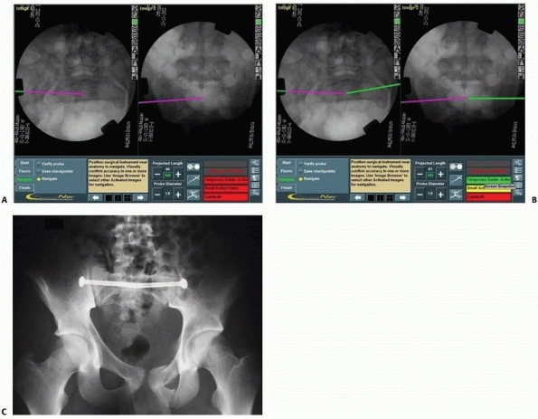
FIGURE 17-13 Bilateral sacroiliac screws. A,B.
Typical intraoperative display of computer screen during bilateral insertion of two sacroiliac screws. The live spatial position of the drill guide is simultaneously presented on two views (inlet and outlet) with a virtual continuation representing the track of the guidewire. C. Postoperative verification radiograph showing the accurate real position of the two sacroiliac screws after the navigation process. (Images property of authors.) |
entire fracture reduction procedure. This became possible because of
the ability to simultaneously track two reference frames. The frames
are attached to the distal and proximal long bone fragments. Several AP
and lateral views are acquired, enabling visualization of the entire
bone. Usually, six views (three AP and three lateral) are needed to
visualize the proximal fragment, the fracture site, and the distal
fragment in two planes. It is possible to virtually define each segment
on the computer display and to track each fragment by navigation as
already described. The special location of each fragment in
relationship to the other enables actual fracture reduction and
insertion of the reduction wire. The procedure resembles the
fluoroscopic process of fracture reduction surgery with two major
advantages: no radiation and simultaneous two-plane tracking. The
ability to track and visualize the entire bone enables the taking of
several measurements including length and rotation. Preliminary data
indicate that this technology is feasible in the clinical setup and may
significantly contribute to the clinical outcome of long bone fracture
reduction (Fig. 17-17). Recently, several
software packages have been developed that also enable the tracking of
implants, particularly fixation plates. Thus, it is possible to track
the position of the implant in relationship to the bone. This technique
overcomes some of the drawbacks of the first generation of computer
navigation systems. In the future, customized tracked instruments based
on these principles will further improve and facilitate computer-aided
intramedullary nailing.10,17,26,34,38,47
technical difficulties. In many cases, the fracture is comminuted and
has complex geometry that is difficult to evaluate on conventional CT
slices or fluoroscopic radiography images. Recently introduced 3D
intraoperative imaging, such as Iso C-arm imaging, is a useful tool for
this visualization. However, it also has limitations, as it can be used
only once or twice during surgery because of radiation exposure and
because it is a static view. Other difficulties
include tracking of small bone fragments and possible fragment motion during fixation.
 |
|
FIGURE 17-14 Sacroiliac and pubic ramus screw. A-C.
An intraoperative display of the computer screen during insertion of a sacroiliac screw and two intramedullary pubic ramus screws. D, E. Inlet and outlet postoperative verification radiographs showing the accurate real placement of the three screws. (Images property of authors.) |
 |
|
FIGURE 17-15 Intramedullary nailing. A.
Typical computer display used during antegrade femoral intramedullary nailing consisting of simultaneous anteroposterior and lateral views, where the pink line represents the guide’s insertion point at the precise entry point in the piriformis fossa and the green line represents the nail’s direction. B,C. Proximal locking hole in the retrograde femoral nail. Note the hole as a perfect circle enabling precise aiming of the locking screw. (Images property of authors.) |
postoperative confirmation of the reduction and fixation of
intra-articular fractures can save patients and surgeons from
uncertainty relating to the quality of reduction. Recent developments
have yielded new options for intraoperative 3D imaging. The SireMobil
Iso-C 3D (Siemens Medical Solutions), for example, combines the
capabilities of routine intraoperative C-arm fluoroscopy with resultant
3D images. The 3D imaging equipment has the ability to automatically
revolve around a fixed surgical target (isocentric) acquiring up to 100
images. Of these images, axial cuts, 2D and 3D reformations can be
generated that are comparable to CT images. Using this unique imaging
modality can help the surgeon to intraoperatively assess fracture
anatomy, including in the vicinity of the acetabulum and the posterior
pelvic ring. The performance of the Iso-C 3D has already been described
in several studies for intraoperative demonstration of high-contrast
skeletal objects, with encouraging results.1,2 The persisting disadvantages of 3D fluoroscopes is a limited image size of 12.5 cm3,
which is sufficient for the sacroiliac joint but not for the entire
posterior pelvic ring, and relatively inferior image quality.
Modifications of the isocentric C-arm have recently been introduced, to
offer superior image quality, increased field of view, higher spatial
resolution, and soft tissue visibility, as well as the elimination of
the need to rotate around a fixed point (isocentricity).
in intra-articular fracture fixation is 3D fluoroscopy-based
navigation. Of the intraoperative axial cuts, 2D and 3D reformations
can be generated and the data can be transferred to the navigation
system. With inherent registration, the navigation procedure can be
performed, similar to CT navigation, but without any registration
procedure.42
fluoroscope (e.g., the Arcadis Orbic; Siemens AG, Erlangen, Germany)
and a multifunctional navigation system onto one common trolley will
markedly improve data transfer and system handling. Thus, the
indications for image guidance in intra-articular fractures, including
pelvic surgery, will be expanded to include reduced open procedures (Fig. 17-18).
situation in which a foreign body is retained in bone or soft tissue,
such as surgical hardware or penetrating injuries with retained metals
(e.g., shrapnel, nuts, and bolts) that need to be removed.
It
is not necessary to track foreign bodies, as they usually remain in
place and do not drift. They can be reached with a navigated tool by
following the tool’s location with respect to them, in the activated
fluoroscopic images. Given the simplicity of the procedure, we
recommend that this be the first surgical procedure using computerized
navigation systems to be performed by inexperienced surgeons.29
 |
|
FIGURE 17-16 Intramedullary nailing: Poller and “miss-a-nail.” A.
Poller screw planning for reduction of a proximal tibial fracture. The red circle depicts the planned position of the Poller screw. The green line is the virtual nail. The surgeon can predict the relationship between the two. B,C. Poller screw insertion process. D,E. “Miss-a-nail” screw through a femoral neck fracture after insertion of a femoral nail with a spiral blade. D. Planning the “miss-a-nail” route with the navigation system displayed as a green line. E. Fluoroscopic image after nail insertion. Note the parallelism between the planned and real route of the nail. (Images property of authors.) |
 |
|
FIGURE 17-17
Fracture reduction. The navigation process of two fragments. The software enables simultaneous tracking of the two fragments, with information regarding length, angulation, and rotation. (Images courtesy of Dr. Y. Weil.) |
discomfort, although other indications include infection or risk of
toxicity. The removal of missiles retained in an inaccessible location
poses a major problem for the trauma surgeon, because they can be
hazardous to the integrity of adjacent internal structures.
these situations. Unlike CT-based systems, it requires very short
preoperative preparation, making it appropriate in emergency situations
as well, where its effectiveness has already been proved, even during
the urgent stages of treatment. Thanks to the high accuracy of
fluoroscopy-based navigation, its use in complex and dangerous
situations where a foreign body is located in the proximity of
structures such as blood vessels and/or nerves is promising. In
comparison to other conventional techniques, the use of
fluoroscopy-based navigation has allowed orthopaedic surgeons to
minimize soft tissue dissection. The same principle can be use for
guided bone biopsy.
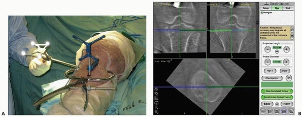 |
|
FIGURE 17-18 Using SireMobil Iso-C 3D (Siemens Medical Solutions, Erlangen, Germany) for fracture reduction. A. Percutaneous reduction of a tibial plateau fracture using reduction instruments with application of a reference frame. B.
Three images displayed on the system’s screen (coronal and sagittal), showing the location of the surgical tool (blue) and allowing for real-time tracking with the virtual green line, which assists in determining the direction of the surgical tool in a three-dimensional environment. (Images property of authors.) |
attached to the patient’s adjacent bone and to a calibrated pointer.
Several fluoroscopic images of the required anatomic site are acquired
and stored in the computer, or 3D information using Iso-C technology is
acquired. The accurate spatial location of the foreign object can be
seen in the images displayed on the computer’s screen (Fig. 17-19).
The surgeon then plans the most accurate and safest minimal surgical
approach toward the foreign body that needs to be removed. Once the
fluoroscopic images have been activated, the location of the guided
probe with respect to the patient’s anatomy is continuously displayed
and updated on all of the fluoroscopic images. This enables accurate
determination of the entry point and spatial advancement of the probe
toward the foreign body.33
-
Loss of line-of-sight
An unobstructed view between the optical camera and the trackers at all
times is the basic requirement of optical navigation. Loss of
line-of-sight occurs when the view between the optical camera and one
or more of the trackers is obstructed by the surgeon or another member
of
P.487the
surgical team, the patient’s body, the fluoroscopy C-arm, the overhead
lamps, or any other object in the vicinity of the surgical field. When
there is no line-of-sight, the tracker, which is not seen, either
disappears from the display or the entire display freezes. Navigation
resumes as soon as the obstruction disappears.![]() FIGURE 17-19 Shrapnel removal. A.
FIGURE 17-19 Shrapnel removal. A.
Preoperative computed tomography scan showing shrapnel that is intended
to be removed because of its proximity to the left hip joint. B.
Four acquired images displayed on the system’s screen, showing the
location of the missile and allowing for immediate presurgical planning
of the percutaneous surgical approach. The pink line represents the
surgical tool and the virtual green line assists in determining the
point of entry and direction of the surgical tool. C. The surgical tool, represented by the pink line, arrives at the missile. D. Verification fluoroscopy followed by removal of the missile. (Images property of authors.)Loss of line-of-sight can be remedied by moving the
object causing the interference, by repositioning the optical camera,
or by changing the surgical team’s location around the patient. In some
situations, because of the surgical approach, it is not possible to see
all of the trackers at once. In this case, partial navigation is
possible with the visible trackers. In some surgical situations,
maintenance of the line-of-sight is not possible and therefore
navigation should be avoided. As previously discussed, the surgeon can
control some of the obstacles by appropriate placement of the trackers
and the camera. Practically, this step should be considered as an
integral part of the preplanning stage of CAOS-ST. -
Shift of the dynamic reference frame rigid bone mounting
Maintaining a rigid attachment between the bone tracker and the bone
throughout surgery is essential in order to guarantee registration
accuracy. Shifting is usually the result of bone fixation loosening,
poor jig fixation, or unintentionally pushing or hitting the tracker
and its mounting jig. An undetected shift will result in inaccurate
navigation images that might mislead the surgeon and lead to undesired
results and complications. To avoid this situation, the surgeon should
ensure that the tracker mounting jig is securely fixated to the bone
structure.The only way to detect dynamic reference frame motion is
by validation. Validation is preformed either by acquiring one or more
fluoroscopic radiography images and comparing
P.488them
with the navigation images, or by touching with the tip of a surgical
tool known anatomic landmarks and verifying that the tool tip appears
close to the landmark in the navigated image. Validation should be
performed at key points during surgery and always when in doubt. -
Tool decalibration
Tool decalibration occurs when the geometric data of the tracked tool
do not match its actual geometry. Tool decalibration is caused by tool
wear and tear (e.g., tip bending, frame deformation because of repeated
sterilization or tool tracker shift). To avoid these situations, the
surgeon should verify tool calibration before surgery, at key points
during the surgery, and always when in doubt. Tool decalibration cannot
be detected automatically. The surgeon must perform a tool calibration
verification procedure, which usually involves the use of custom
calibration software and hardware. -
Navigation image inaccuracy
Inaccuracy of navigation images is the mismatch between the displayed
images and the intraoperative situation. The inaccuracy is the result
of errors in the registration chain. The main causes of the errors
include the shift of the dynamic reference frame, tool decalibration,
and the shift of the C-arm tracker ring. Secondary causes include
tracking system drift over time and navigation at the edge of the
position sensor working volume. Other causes are related to the images
themselves. In CT images, they include poor contrast, low slice
resolution, insufficient radiation dose, large spacing between slices,
patient motion during the CT scan, and blooming artifacts as a result
of the presence of metallic objects. In fluoroscopic radiography
images, they include poor image resolution, poor contrast because of
insufficient or excessive radiation, inappropriate viewpoints, and
patient motion during image acquisition.The surgeon must realize that the acquired images serve as the basis for the entire navigated surgical procedure.18,20,39
Therefore, optimization of these images (contrast, field, viewing
angle, etc.) is crucial and should be done during the image acquisition
stage, before surgery begins. Note that navigation image inaccuracy can
be observed by the surgeon but cannot automatically be detected. It
requires performing validation tests for C-arm ring and dynamic
reference frame shift, tool decalibration, restarting of the tracking
system, repositioning of the position sensor, and the acquisition of
new images.27 -
System robustness issues
Robustness is the ability of a system to perform its intended tasks
with a minimum number of failures over time. The more robust the
system, the more acceptable it will be to the surgeon. Robustness
depends on both software and hardware components. Software failures
include flaws in the computer operating system, in the custom-designed
software, and in the tracking base unit controller. At best, software
flaws can be temporarily overcome by restarting the system. At worst,
they require preempting navigation and reporting the flaw to the
company. Hardware failures include failure of the computer unit, poor
cable connections, and failure of the tracking unit. -
Verification of surgical tool and implant spatial position
The surgeon should always remember to make a distinction between the
virtual and nonvirtual situations displayed on the computer screen.
This is of great importance, especially in trauma surgery, because the
surgeon is used to working under fluoroscopic guidance that provides a
true view of the surgical site as opposed to the virtual display in
CAOS-ST procedures. For example, a perfect virtual position of a
guidewire may be a false presentation of the real situation, because
during insertion of the real guidewire, it may slip or bend and point
to a wrong position, without being detected or shown on the augmented
image. There are several ways to tackle this critical obstacle. The
best is to use to use rigid guidewires to prevent bending. Moreover,
the first obstacle is penetrating the cortical bone in the right
location. Experience and/or the use of rigid drills can usually
overcome this problem. In addition, it is also very important to
perform real-time fluoroscopic verification at critical or questionable
time points during the surgical procedure. -
Adaptation to different surgical techniques
The main addition to computer-assisted navigation compared with
conventional fluoroscopic trauma surgery is the bone-mounted reference
frame. The significant ramifications of the loosening of the reference
frame have been previously described. The actual location of this frame
can interfere during the surgical procedure. For example, while
inserting the reference frame screw into the bone diaphysis during
intramedullary nailing, it should not penetrate the medullary canal. In
addition, during the insertion of a locking screw, the reference frame
might be in the way and prevent either an accurate line-of-sight or the
proper positioning of certain surgical instruments (e.g., drills). The
surgeon must choose between placing the frame close to the operative
site, to increase accuracy of the procedure and to improve
triangulation, and placing the frame where it establishes a convenient
working distance.
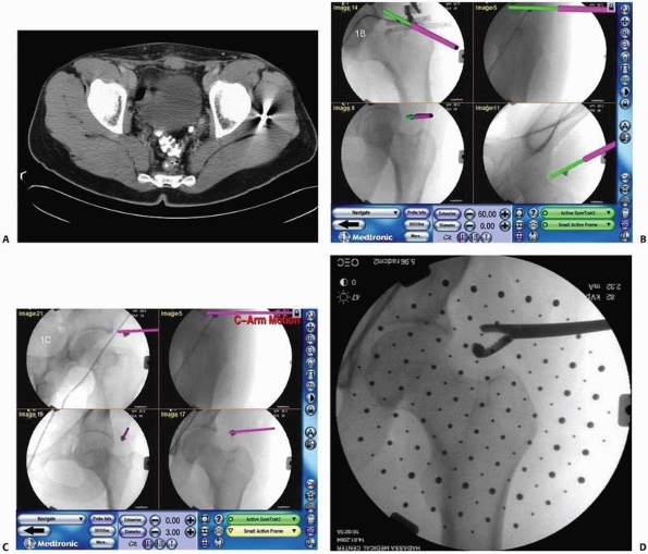
Currently, their main limitations, in decreasing order of importance,
and perspectives for improvements are as follows:
-
Support for implants and instrumentation
Navigation systems are designed to be used with specific tools,
implants, and hardware from specific manufacturers. The choice of
supported instruments and implants depends on decisions made by the
navigation and instrument companies, which are primarily dictated by
commercial interests. Often, the software module only accepts models
from one manufacturer. In some cases, tools from other manufacturers
can be incorporated following a tool calibration procedure. Currently,
only a handful of instruments and implants are supported. -
Support for surgical procedures
Navigation systems require software modules (software surgical
protocols) that implement the surgical protocol for navigation for
specific procedures. Without the custom software module for the
surgical procedure, the navigation system cannot be used, although in
principle it is technically feasible in procedures other than those for
which they were designed. Currently, only a handful of procedures are
supported. -
Improvements in tracking technology
Current optical tracking technology has several drawbacks, including
line-of-sight, size of trackers, cables, number of trackers, accuracy,
and cost. Magnetic tracking offers a variety of potential advantages,
including no line-of-sight requirement, reduced tracker size, and
reduced cost. Although the technology is
P.489not
as yet ready for routine clinical use, it is likely that some of the
obstacles will be overcome in the near future, offering the possibility
of tracking bone fragments and easing tracker fixation to the bone,
thus significantly reducing or eliminating dynamic reference frame
shift and opening the door for navigation during reduction. -
Image-based CT registration
Current CT-based navigation systems require the surgeon to acquire
points on the surface of the anatomy of interest to perform the
registration between the CT data set and the intraoperative situation.
This precludes its use in percutaneous procedures because it is time
consuming and error prone and produces suboptimal registration results.
An alternative is to use fluoroscopic radiography images instead of
points harvested from the bone surface. This type of registration,
called anatomy-based CT to fluoroscopic radiography registration, has
been demonstrated in the laboratory and will be available in navigation
systems. -
Planning
Current intraoperative planning is either nonexistent or limited at
best. Intraoperative definition of goals, such as screw path safety
zone and insertion axis, can greatly help the surgeon perform the
surgery. The blurring of the distinction between preoperative and
intraoperative planning opens the door for better, more adaptive
planning and consequently better and more consistent results. -
Spatial visualization without CT
A drawback of fluoroscopy-based navigation systems is that they do not
show spatial views of the intraoperative situation, which can only be
produced when CT data are available. Isometric fluoroscopic technology
(Iso-C) overcomes this obstacle; however, it provides a relatively
small visual field. Newly design technology is now available with
better quality and a larger view. Another way to overcome this
limitation has been proposed—to acquire several fluoroscopic
radiography images and adapt a closely related CT or generic anatomic
model so as to match the patient-specific fluoroscopic radiography
images. This approach, called atlas-based matching, is currently under investigation. -
Ergonometric factors
Most operating rooms were not designed with new technology in mind in
terms of size; placement of the computer, computer screen, and cables;
and so on. A surgeon experienced with CAS can appreciate the advanced
ease of use in newer generations of navigation systems. However, the
insertion of a navigation system into the operating room still warrants
special consideration. The machine occupies space. Its positioning is
dictated by lines-of-sight between the tracker sensor and the markers.
orthopaedic trauma surgery is rather new. The four main contributions
to trauma surgery are as follows:
-
Facilitates minimal invasive surgery
(MIS) by reducing soft tissue damage, thus shortening the postoperative
rehabilitation process -
Improves the accuracy of fracture
reduction and implant placement compared with that obtained with
conventional methods and reduces outcome variability -
Significantly reduces radiation exposure to both the patient and the surgeon
-
Creates a powerful educational and quality control tool
preplanning stage. If we take, for instance, the imaging field, it is
clear that computerized imaging supplies a better 3D understanding that
may influence the planning of the surgical procedure. Undoubtedly, this
new technology can and should change our way of thinking in relation to
other stages of surgical treatment.
are continuously advancing and offer additional possibilities. Although
these systems are taking their first steps, it appears that they have
already managed to change the setting in several trauma centers. The CT
suite can be transformed into an operating room or, alternatively, the
modern hi-tech fluoroscope can now be altered to produce 3D images.
These modern available technologies, on the one hand, and surgeons’
preferences and compliance, on the other, will in the future determine
the setup of the operating room, where it will be situated and so
forth. Future generations of computerized navigation systems will be
characterized not only by improved accuracy but also in diminishing the
robustness and improving working convenience in the computerized
environment. When these changes finally take place, it is expected that
computerized technology will be of assistance not only in navigation
but also in the execution of the surgical procedure by means of robots.45
If the trauma surgeon can overcome the difficulties entailed in
integrating the new technology, we may experience a revolution in
surgical approaches and education.
representation of the relevant characteristics (e.g., shape, location,
main axis) of an object of interest (e.g., a bone, bone fragment,
surgical instrument, implant, fixation plate, cutting plane). Synonym: digital template
description of a bone surface consisting of a collection of
interconnected points, usually extracted from CT data. Synonym: surface model
Navigation with images created by superimposing onto preoperative CT
cross section and spatial images the surgical tool silhouette and
updating its location in real time.
Navigation using images created by superimposing onto conventional
fluoroscopic images the surgical tool silhouette and updating its
location in real time, thereby creating the impression of continuous
fluoroscopy without the ensuing radiation. Synonyms: virtual fluoroscopy, augmented fluoroscopy
determining the spatial location of surgical instruments and anatomic
structures in real time for the purposes of guiding surgical gestures
during surgery.
that shows the current location of surgical instruments with respect to
images of the anatomy and continuously updates this image as the
instruments and bone structures move. It requires tracking,
registration, visualization, and validation. Synonyms: surgical navigator, guidance system
requirement of optical tracking systems in which there must be no
occluding objects between the position sensor and the trackers..
Mechanical jigs, such as screws and clamps, used to rigidly attach
trackers to surgical instruments and bone structures and whose purpose
is to mechanically fix their positional relationship. Synonym: attachment
obtains the position and orientation of trackers by measuring spatially
dependent physical properties, such as optical and magnetic properties.
Synonym: localization system
means by which the location of trackers is measured. Tracking
technology is optical or magnetic. Optical tracking is active
(light-emitting diodes), passive (reflective spheres), or hybrid (both
active and passive), and is called semiactive. Synonym: localization technology
instrument’s capability to approach a true or absolute value. Static
accuracy refers to measurements that do not change over time, while
dynamic accuracy refers to time-varying measurements. Accuracy is a
function of both bias and precision.
measurements per second. Static accuracy refers to measurements
obtained when the trackers are at rest, while dynamic accuracy refers
to measurements obtained as the trackers move. Synonyms: rate, frame rate, display rate
resolution and stability. Resolution is the smallest discernible
difference between two measurements. Stability refers to measurements
made at steady state and over a sufficiently long period of time.
reference within which the spatial locations of objects can be
described. Each object of interest has its own coordinate frame.
Synonym: coordinate system (COS)
establishing a common reference frame between the preoperative CT
images and the intraoperative situation. Synonyms: point registration, surface registration, contact registration
Tracker attached to the bone used to track the bone motions to
determine the relative location of the bone with respect to the tool.
Synonyms: reference, reference base, dynamic reference base (DRB), dynamic referencing
computing the transformation and the tool’s geometric features, such as
its main axis and its tip position. Tool calibration verification is
the process of comparing the actual and computed calibration. The tool
calibration unit is the device used for calibrating tools.
description of the relationship between the locations of two objects.
Transformations are static (constant) when the relative locations of
the objects do not change, dynamic otherwise. There are four types of
transformations: tracking transformations, tools transformations, image
transformations, and display transformations.
verifying that the navigation images match the clinical intraoperative
situation. There are three types of validation: tool calibration
validation, dynamic reference frame validation, and registration
accuracy validation. Synonym: verification
K, Finkelstein J, Khoury A, et al. CT (ISO-C-3D) image-based
computer-assisted navigation in trauma surgery: a preliminary report.
Injury 2008;39:39-43.
K, Finkelstein J, Khoury A, et al. The use of intraoperative
three-dimensional imaging (ISO-C-3D) in fixation of intraarticular
fractures. Injury 2007;38:1163-1169.
N, Lindsey RW, Starr AJ, et al. The use of a virtual three-dimensional
model to evaluate the intraosseous space available for percutaneous
screw fixation of acetabular fractures. J Bone Joint Surg Br
2005;87B:1520-1523.
J, Peele M, Ricci WM, et al. Validation of CT-reconstructed images for
the evaluation of acetabular fractures. Proceedings of the American
Academy of Orthopedic Surgery, 2004, San Francisco: 610.
M, Kristan A. Preoperative planning in pelvic and acetabular surgery:
the value of advanced computerized planning modules. Injury
2007;38:442-449.
M, Hüfner T, Geerling J, et al. Navigated percutaneous pelvic
sacroiliac screw fixation: experimental comparison of accuracy between
fluoroscopy and Iso-C 3D navigation. Comput Aided Surg 2006;11:209-213.
AC, Kahler DM. Closed reduction and percutaneous fixation of anterior
column acetabular fractures. Comput Aided Surg 2002;7:169-178.
MJ, Citak M, Kendoff D, et al. Femoral fracture malrotation caused by
freehand versus navigated distal interlocking. Injury 2008;39:176-180.
E, Bachler R, Heini PF, et al. Accuracy of computer-guided screw
fixation of the sacroiliac joint. Clin Orthop 2001;393:310-317.
PA, Hebecker A, Waelti H, et al. Clinical study for registration-free
3D navigation with the SIREMOBIL Iso-3D mobile C-arm. Electromedica
2003;71:6-15.
E, Joskowicz L. Computer-assisted image-guided intramedullary nailing
of femoral shaft fractures. Techn Orthop 2003;18:191-201.
AF, Giannoudis PV, Smith RM. Fluoroscopy based multiplanar image
guidance for insertion of sacroiliac screws. Clin Orthop
2002;395:135-144.
R, Slomczykowski M, Krettek C, et al. Computer-assisted
fluoroscopy-based reduction of femoral fractures and anteversion
correction. Comput Aided Surg 2000;5: 311-325.
T, Pohlemann T, Tarte S, et al. Computer-assisted fracture reduction of
pelvic ring fractures: an in vitro study. Clin Orthop 2002;399:231-239.
I, Weil YA, Joskowicz L, et al. Fracture-table-mounted versus
bone-mounted dynamic reference frame tracking accuracy using
computer-assisted orthopaedic surgery: a comparative study. Comput
Aided Surg 2007;12:125-130.
L, Milgrom C, Simkin A, et al. FRACAS: a system for computer-aided
image-guided long bone fracture surgery. Comput Aided Surg
1999;3:271-288.
DM. Computer-assisted closed techniques of reduction and fixation. In:
Tile M, Helfet D, Kellam J, eds. Surgery of the Pelvis and Acetabulum.
Philadelphia: Lippincott Williams & Wilkins, 2003:604-615.
DM. Virtual fluoroscopy: a tool for decreasing radiation exposure
during femoral intramedullary nailing. Stud Health Technol Inform
2001;81:225-228.
A, Liebergall M, Weil Y, et al. Computerized fluoroscopic-based
navigation-assisted intramedullary nailing. Am J Orthop 2007;36:582-585.
S, Sautot P, Troccaz J, et al. Computer-assisted spine surgery: a
technique for accurate transpedicular screw fixation using CT data and
a 3D optical localizer. Comput Aided Surg (formerly J Image Guid Surg)
1995;1:65-73.
M, Ben-David D, Weil Y, et al. Computerized navigation for the internal
fixation of femoral neck fractures. J Bone Joint Surg Am
2006;88A:1748-1754.
H, Yaniv Z, Joskowicz L. Robust automatic C-arm calibration for
fluoroscopy-based navigation: a practical approach. Proceedings of the
Fifth International Conference on Medical Computing and Computer-Aided
Intervention. Lecture Notes in Computer Science 2488, Springer Verlag
2002;2:60-68.
R, Khoury A, Weil Y, et al. First generation of fluoroscopic navigation
in percutaneous pelvic surgery. J Orthop Trauma 2004;18:106-111.
R, Weil Y, Khoury A, et al. The use of computerized navigation in the
treatment of gunshot and shrapnel injury. Comput Aided Surg
2004;9:39-43.
R, Weil Y, Peleg E, et al. Computerized navigation for closed reduction
during femoral intramedullary nailing. Injury 2005;36:866-870.
RN, Webb LX. Computed-assisted preoperative planning in the surgical
treatment of acetabular fractures. J Surg Orthop Adv 2007;16:138-143.
NW, Haverlag R, van Vugt AB. Computer-assisted versus conventional
surgery for insertion of 96 cannulated iliosacral screws in patients
with postpartum pelvic pain. J Trauma 2004;57:1299-1302.
MA, Hofstetter R, Sati M, et al. Novel computer-assisted fluoroscopy
system for intraoperative guidance: feasibility study for distal
locking of femoral nails. J Orthop Trauma 2001;15:122-131.
U, Schaser K, Konig B. Image guidance in pelvic and acetabular surgery:
expectations, success, and limitations. Injury 2007;38:450-462.
N, Jacob AL, Nolte LP, et al. Surgical navigation based on fluoroscopy:
clinical application for computer-assisted distal locking of
intramedullary implants. Comput Aided Surg 2000;5:391-400.
R, Lavallee S, Burdea C, et al. Computer-Integrated Surgery: Technology
and Clinical Applications. Boston: The MIT Press, 1995.
Y, Liebergall M, Khoury A, et al. The use of computerized fluoroscopic
navigation for removal of pelvic screws. Am J Orthop 2004;33:384-385.
YA, Gardner MJ, Helfet DL, et al. Computer navigation allows for
accurate reduction of femoral fractures. Clin Orthop Relat Res
2007;460:185-191.
YA, Liebergall M, Mosheiff R, et al. Long bone fracture reduction using
a fluoroscopy-based navigation system: a feasibility and accuracy
study. Comput Aided Surg 2007;12:295-302.