
One – General Principles: Basics > Principles of Treatment > 16 –
Imaging Considerations in Orthopaedic Trauma
trauma contributes greatly to the initial diagnosis and subsequent
management of orthopaedic injuries. In many instances, patients are
able to provide details of the injury, and imaging studies often
confirm or exclude diagnoses already suggested by the clinical history,
mechanism of injury, and physical examination findings. Imaging plays a
critical role in the management of multitrauma patients who arrive
obtunded or unconscious or are intubated and therefore unable to
localize symptoms or cooperate during the physical examination.
Multitrauma patients may also have coexisting neurological and visceral
injury, and in this setting orthopaedic imaging is often deferred for
other imaging studies and surgical triage for life-threatening
injuries. However, plain radiographs must be made of all potential
musculoskeletal injuries as soon as possible so that appropriate early
treatment decisions are made.
clinical practice today, and use of a particular modality may be
influenced by multiple factors, such as availability, image resolution,
invasiveness, cost-effectiveness, patient risk, and requirements for
special handling of the trauma patient. Many imaging studies are
routinely ordered for specific indications and need no justification;
for example, conventional radiographs are used to evaluate acute bony
trauma of the extremities. Particularly with regard to more advanced
imaging techniques, however, clinicians must often consider these
tradeoffs in deciding whether to pursue additional imaging.
conventional radiography in both clinical and hospital settings, there
is more variable access to advanced imaging modalities, particularly in
rural communities and after hours. Although data are lacking, it has
been previously estimated that only 10% of hospitals offer full
radiology coverage to emergency departments 24 hours per day.83,163
Many emergency departments do have continuous access to computed
tomography (CT) scanners, but access to more advanced imaging
modalities, such as ultrasound (US), nuclear medicine (NM), and
magnetic resonance imaging (MRI), varies significantly among hospitals
and communities and may be available only on an “on-call” basis or not
available at all after hours.
orthopedic trauma patient in the immediate setting are plain
radiographs, which provide information sufficient to diagnose any
fracture or dislocation. The primary exception to this is in the
evaluation of the spine, especially in the comatose patient and in the
setting of specific injury patterns, where both CT and MRI have
well-defined roles.56,70,72
However, controversy continues over the relative merits of CT versus
MRI in the evaluation of spine trauma, with one group considering that
MRI is the new standard for the evaluation of blunt cervical spine
trauma.132 Although MRI has the
added benefit of more clearly demonstrating soft tissue injuries in
general, and disc herniation in the spine in particular, the
inconsistent after-hours availability of MRI, as well as the obvious
logistic problems of transporting and monitoring a trauma patient
within an MRI unit, means that CT will remain the most common method of
imaging the spine in the early evaluation of the trauma patient.173
teleradiology provides a means to obtain after-hours interpretation of
images by trained radiologists.54,126,154,178
Although this is most often done in the management of acute
neurological emergencies and in the assessment of cross-sectional
imaging of the abdomen and chest, such technology will no doubt benefit
musculoskeletal trauma patients as well. In a recent report describing
the benefits of a nighttime teleradiology service for emergencies, 43
of 75 studies were musculoskeletal.54
part, be influenced by spatial resolution and contrast resolution. The
ability of an imaging modality to resolve small objects of high subject
contrast (e.g., bone-muscle interface) as distinct entities is referred
to as spatial resolution, which is typically measured in line pairs per
millimeter (lp/mm); higher values of lp/mm indicate greater resolution.
For comparison, the limiting spatial resolution of the human eye is
approximately 30 lp/mm. Resolution may also be expressed in
millimeters, whereby smaller values represent greater spatial
resolution. Table 16-1 lists representative
values of limiting spatial resolution for common imaging modalities.
Conventional radiographs have considerably better spatial resolution
than cross-sectional imaging techniques, although overlapping bony
structures often complicate evaluation of osseous anatomy. CT has
better spatial resolution than MRI and is more commonly performed for
evaluating finer bony abnormalities, such as avulsion fractures and
calcification within tumor matrix.
|
TABLE
16-1 The Limiting Spatial Resolutions of Various Medical Imaging Modalities: The Resolution Levels Achieved in Typical Clinical Usage of the Modality |
||||||||||||||||||||||||||||||||||||||||||||||||||||
|---|---|---|---|---|---|---|---|---|---|---|---|---|---|---|---|---|---|---|---|---|---|---|---|---|---|---|---|---|---|---|---|---|---|---|---|---|---|---|---|---|---|---|---|---|---|---|---|---|---|---|---|---|
|
||||||||||||||||||||||||||||||||||||||||||||||||||||
to the ability to resolve two tissues of similar subject contrast.
Conventional radiographs typically have poor soft tissue contrast
resolution, whereas CT and MRI, in particular, have much better
contrast resolution, in part related to their tomographic nature. For
example, on conventional radiographs, subcutaneous fat may be discerned
from the underlying muscle groups, although the intermuscular fascial
planes cannot be visualized. CT and MRI better demonstrate the
subcutaneous fat and intermuscular fascial planes, although MRI shows
superior soft tissue contrast resolution compared with CT.
require minimally invasive procedures, such as placement of intravenous
access for contrast administration. Some imaging techniques are more
invasive, however, such as peripheral angiography for vascular
assessment in the trauma patient, and not
only
carry more inherent risk to the patient but also require greater
resources and coordination on an emergent basis. When used
appropriately, the diagnostic and therapeutic advantages of these
procedures can contribute substantially to the patient’s management.
have been performed to address the cost-effectiveness of algorithms
incorporating conventional radiography in the diagnosis and follow-up
of musculoskeletal trauma.6
Significant costs may be incurred at receiving hospitals as a result of
repeating radiographic workups for patients who have been transferred
from referring facilities along with their original radiographs.171
Several recent studies have shown the benefits of “rules” in deciding
when to order radiographs for knee and ankle trauma, resulting in fewer
radiographs ordered and reduced cost without increased incidence of
missed fractures.* Additional studies have also shown the
ability to reduce postoperative and follow-up radiographs in treatment
of ankle fractures.78,125
Similar studies have addressed the cost-effectiveness of routine pelvic
radiography in the setting of blunt trauma, although with mixed results.49,89
Study of pediatric torus fractures has shown that postcasting
radiographs are unnecessary and follow-up radiographs do not change
fracture management, with the implication of significant cost-savings
as a result of decreased radiography.59
the United States, an area of particular concern is the perceived
expense of advanced musculoskeletal imaging techniques such as MRI.
According to one estimate, the use of musculoskeletal MRI has grown
nearly 14 times faster than overall musculoskeletal imaging during the
period 1996-2005 (353% increase versus 26% increase).142 Parker et al.142
explored the possible cost-savings that could be realized if ultrasound
was used instead of MRI for the diagnosis of musculoskeletal disorders.142
According to their review of 3621 musculoskeletal MRI reports, 45.4% of
primary diagnoses and 30.6% of all diagnoses could have been made with
US instead.142 By extrapolating these data into the future, Parker et al.142
predict that the substitution of musculoskeletal US for MRI in
appropriate cases could save more than $6.9 billion in the period
2006-2020 and lead to large cost-savings for Medicare.142
very cost-effective to the degree that such imaging improves initial
diagnostic accuracy and avoids delays in treatment that can contribute
to increased morbidity to the patient or delay to return to work. For
example, several studies have shown that early MRI in cases of wrist
trauma can be cost-effective by providing accurate diagnosis of
scaphoid fractures in cases where initial conventional radiography was
normal.25,46,117
MRI also proved superior to follow-up radiography for diagnosis of
occult fractures, resulting in a change in management in up to 89% of
cases.152 Cost was found to be
similar or reduced in all studies comparing early MRI with more
traditional algorithms of casting and radiographic follow-up.25,46,160 Two studies showed cost benefits associated with earlier rather than later MRI scanning.25,152 Similar studies have shown the cost-effectiveness of early limited MRI in the diagnosis and management of occult hip fractures.110
orthopaedic trauma contribute very little increased risk to the
patient. However, potential risks include patient handling, ionizing
radiation, and contrast reactions.
care, especially when transferring patients from gurneys onto imaging
equipment. Many trauma patients have potential spine injuries,
necessitating the use of spinal precautions and special radiographic
views during imaging procedures. Likewise, fractured limbs may be very
painful when moved, and there may be changes in fracture reduction or
redislocation of an injured joint during manipulation of an extremity
for radiographs. Because of pain and disorientation, patients may be
unable to lie still during imaging examinations and may require
analgesia and sedation. Sometimes, mechanical ventilation and multiple
lines as well as catheters must be managed. Life support equipment and
external fixation devices may also be incompatible with or limit the
usefulness of certain examinations, such as conventional radiography
and MRI.
with modality; CT generates considerably higher radiation does compared
to conventional radiography, while US and MRI do not involve ionizing
radiation. Radiation doses also vary considerably among CT protocols
and between manufacturers.155 One
study showed a 61% to 71% decrease in radiation dose between
standard-dose and low-dose multidetector CT in cervical spine trauma.133
It has been estimated that as many as 1.5% to 2.0% of all cancers in
the U.S. patients may be attributable to radiation from CT studies.24,38
CT is often used to evaluate to evaluate the multiply-injured and
unconscious patient. These patients typically undergo head and body CT
for evaluation of intracranial and body trauma, and the use of CT to
clear the cervical spine, in lieu of conventional radiography, may be
increasing. Body CT generates the greatest radiation dose. In the
cervical region, the greatest risk of ionizing radiation is induction
of thyroid malignancy. One study suggests that use of CT to clear the
cervical spine in unconscious major trauma patients is justified given
the relatively minor concern for inducing thyroid malignancy. However,
in those patients who are conscious or with a Glasgow Coma Scale score
between 9 and 12, clinical evaluation is more likely to be helpful, and
the risk of thyroid malignancy in a young cohort does not justify the
use of CT to clear the entire cervical spine.155
carries a small risk of adverse events, which may be categorized as
mild, moderate, severe, and end organ.3
With traditional high-osmolality ionic contrast media, most adverse
reactions are mild to moderate and occur in 5% to 12% of all patients.
This incidence is significantly decreased with use of the newer
low-osmolality nonionic contrast agents. The occurrence of severe
contrast reactions is approximately 1 to 2 per 1000 patients receiving
high-osmolality contrast agents, whereas this number decreases to
approximately 1 to 2 per 10,000 patients receiving low-osmolality
contrast media.4 Examples of
end-organ adverse events include thrombophlebitis related to the
injection site, nephrotoxicity, pulseless electrical activity,
seizures, and pulmonary
edema.3
Peripheral angiography carries a low risk of complications, including
bleeding and further vascular injury, although these problems may be
minimized with experience and careful technique.
(screen film radiography, plain film radiography) involves the use of
x-rays, which are high-energy electromagnetic radiation with
wavelengths smaller than ultraviolet light but longer than gamma rays.
X-rays are produced using an x-ray tube, whereby electrons are emitted
from a heated tungsten filament and accelerated across a voltage
potential to strike an opposing tungsten target. The flow of electrons
from filament to the target results in a tube current, and its
interaction with the tungsten target generates a spectrum of x-rays and
heat. Before leaving the x-ray tube, the x-rays are filtered and
collimated into a useable beam. Factors that are set by the
technologist to vary the quality and/or quantity of the x-ray beam
include the voltage potential (measured in peak kilovoltage [kVp]),
tube current (milliamperes [mA]), and exposure time (seconds). The
output of the x-ray tube is expressed in mAs, calculated by multiplying
the tube current (mA) by the exposure time (s). These factors are
routinely recorded on digital radiographs, whereas they may be
handwritten on portable radiographs for use with future examinations.
through the patient and onto a screen/film cassette. The x-ray beam is
attenuated as it passes through the patient, primarily via two
processes: the photoelectric effect and Compton scatter. After passing
through the patient and before reaching the screen/film cassette, the
transmitted radiation may be further collimated using a lead grid to
remove the scatted radiation. Scatter increases with increasing patient
thickness and larger fields of view and is a significant source of
image degradation. Scatter may be negligible with extremities, in part
related to their smaller size and greater proximity to the cassette;
hence, grids may not be required.
transmitted radiation and create the latent image. Intensifying screens
absorb x-ray photons and subsequently emit a greater number of light
photons, which are then absorbed by the film. The film consists of a
base, which is covered on one or both sides by an emulsion containing
silver grains. Absorbed light photons result in liberation of free
electrons within the emulsion, which subsequently reduce the silver
atoms. When the film is developed, the reduced silver atoms are
amplified and appear black on the film. Most screen/film cassettes use
a dual-screen and dual-emulsion film combination, which is enclosed in
a light-tight cassette and ensures good contact between the screens and
film. To improve bone detail, a single-screen, single emulsion system
may be used.
used to evaluate acute trauma patients, and its use may be complicated
by several factors not encountered in the radiology department’s
controlled environment. Trauma patients frequently are immobile and
require special handling precautions, which may make it difficult to
obtain routine anteroposterior (AP) and lateral projections.
Appropriate placement and alignment of the screen/film cassette may be
especially challenging, and if placed behind a backboard or beneath the
patient’s cart, it may introduce artifacts into the radiograph and
obscure anatomy of interest. Objects outside of the patient’s body
related to his or her resuscitation, including endotracheal tubes,
nasogastric tubes, chest tubes, and intravenous access, frequently
project onto the radiograph. Casts, splints, and other external
fixation devices may also project onto extremity radiographs and limit
visualization of underlying bony detail.
(kVp) and mA, also need modification with portable radiography.
Portable examinations are often performed with higher kVp settings,
which provide for a wider margin of error in selecting other technical
factors. Higher kVp values will result in greater scattered radiation,
however, and may necessitate the use of a grid with the screen/film
cassette. Precise alignment of the grid and cassette to the central
beam of the portable x-ray tube is also more difficult because each of
the components are not fixed in space, and malalignment results in
significant obscuration of the image and degradation in image quality.
application of conventional radiography, where the objective is to
image a specific plane of tissue within the body. Historically, its
primary use in orthopedic trauma was the imaging of suspected fracture
nonunion. Once commonly practiced, plain tomography has been largely
replaced by more advanced cross-sectional imaging techniques such as CT
and MRI. The use of these advanced technologies has led to a decline in
availability of tomography equipment in most imaging departments and a
corresponding decrease in technologist experience in performing such
examinations. However, it remains a viable low-cost and low-risk
alternative to CT in those centers where conventional tomography is
still available.
radiography system whereby the patient is kept stationary while the
x-ray tube and film cassette move about the patient, usually in a
linear fashion but in opposite directions. Structures within the focal
plane of interest are imaged in the same relative location on the film
during tube and cassette translations, whereas images of structures
located in front or behind the desired plane are blurred out by
spreading their images over the entire film. The disadvantages of
tomography include long examination times and potential for significant
radiation exposure to the patient with larger numbers of images.
acquiring radiographs are in use and continue to be refined. In all DR
systems, the creation of x-rays and attenuation of the x-ray beam as it
passes through the patient are similar to conventional radiography
systems. What differentiates DR systems is the type of image receptor
that interacts with the attenuated x-ray beam to create a medical image.
late 1970s and has gained wide popularity in radiology departments
within the last decade. With CR, the screen/film cassette is replaced
by a cassette containing a photostimulatable phosphor deposited onto a
substrate. When this type of phosphor interacts
with
x-rays, electrons are elevated to and trapped at higher energy levels
within the phosphor. The amount of electron trapping is proportional to
the incident x-rays and results in the creation of a latent image,
which can later be read using a specialized CR cassette reader. The
reader scans the phosphor plate using a laser, which releases the
electrons from their higher energy states, and results in emission of
light as they drop down to lower energy states. The emitted light is
captured by a photomultiplier tube, which converts the light into an
electrical signal, which is subsequently digitized and stored. This
process is done on a point-by-point basis throughout the entire
phosphor plate to create a digital image.
led to a new digital imaging technology that has been referred to as
direct capture radiography, or alternatively, indirect and direct DR.
Each of these systems uses flat panel detectors that incorporate a
large array of individual detector elements; each one corresponds to a
pixel in the final image. In indirect DR, the detector elements are
sensitive to light; hence, an x-ray intensifying screen is used to
convert the incident x-rays into light, which is then captured by the
individual detector elements and stored as a net negative charge. In
direct DR, the individual detector elements are coated with a
photoconductive material (selenium is commonly used). On exposure to
x-rays, electrons are liberated from the photoconductor and are
captured by the underlying detector elements, resulting in a net
negative charge within each detector element. With both systems, the
negative charges within the array of detector elements are read out
electronically, digitized, and stored to create the final image.
radiography is greater than for DR systems. CR and DR, however, offer
significant advantages over conventional radiography, including the
ability to manipulate digital images and alter image contrast,
decreased radiation dose to the patient and radiological personnel, and
greater ease of storage and transmission of radiographs both within and
beyond the imaging department. DR systems are expensive to implement,
as they require replacement of the entire radiography suite. CR systems
are much more economical to implement, as they only require replacement
of the screen/film cassettes and purchase of a CR reader. Both digital
systems, though, offer ongoing cost savings as a result of decreased
numbers of retakes and reduction in film costs. Although DR is likely
the future of radiography, it currently does not match conventional
radiography for fracture assessment in terms of spatial resolution (Table 16-1).
modality for assessing fractures and dislocations. Orthogonal views,
occasionally supplemented by additional specific projections, are
sufficient to identify and manage most fractures. Orthopaedic surgeons’
immediate interpretation of conventional radiographs of simple
fractures has been shown to be timely, accurate, and inexpensive and
contributes to patient care, whereas formal interpretation of the same
studies by a radiologist typically occurs after care is rendered, may
be inaccurate, adds expense, and does not contribute to patient
management.21
In addition to delineating the fracture pattern, conventional
radiographs are useful for assessing limb length and alignment and are
the primary means by which fracture healing is monitored. Numerous
examples of the use of conventional radiographs are found throughout
this text. In many cases, more subtle indications of injury apparent on
conventional radiographs can suggest the need for further diagnostic
imaging or intervention. Examples of such cases would be the
identification of a posterior fat pad sign in a pediatric elbow,
indicating an occult elbow injury, a joint effusion, or the finding of
a fat-fluid level in the knee joint capsule indicating osteochondral
fracture. Surrounding soft tissues may also be evaluated for and show
additional evidence of trauma, including swelling, foreign bodies, and
gas. Although conventional radiographs are universally used for
assessing fracture healing, one recent report noted that there is very
poor interobserver agreement regarding the determination of fracture
healing after internal fixation.40
provided a platform on which to develop new methods of musculoskeletal
imaging. Digital imaging facilitates computer processing of images,
which may improve their diagnostic value. Botser and colleagues22
studied a series of nondisplaced proximal femoral fractures and found
that digital enhancement with the use of specific filter techniques
improved fracture diagnosis. One recent advance is a full body scanner
that can take rapid digital images of the entire body in one or
multiple planes (Statscan Critical Imaging System; Lodox Systems Ltd.,
South Africa). The use of Statscan in the evaluation of multiple trauma
patients and pediatric patients has been reported.57,134,147
The primary advantages are the rapid detection of injuries and less
time needed for resuscitation. In one study, 96% of fractures were
identified on the initial Statscan.147
In another study focusing on 37 consecutive pelvic injuries, findings
on Statscan images were compared to those seen with CR and CT.134
Of 73 abnormalities noted in these patients, 18 were not identifiable
on the Statscan, although only one of the missed findings was
considered significant for the initial management of the patient.134
Although many patients initially evaluated with Statscan still need
formal CT, such studies can be more limited and result in less overall
radiation exposure to the patient than conventional imaging algorithms.57
of low-dose x-rays to image patient anatomy at high temporal
resolutions—that is, in real time. Typical components of a fluoroscopy
system include an x-ray tube, filters, and a collimator, similar to
that used in conventional radiography. The x-ray tube is energized
continuously using a low exposure rate, and the x-ray beam is directed
through the patient onto an image intensifier. The image intensifier is
responsible for converting the attenuated x-ray beam into a visible
light image, which is frequently coupled to a closed-circuit television
camera to produce a “live” image on a video monitor. An optical
coupling system, using high-resolution lenses and mirrors, may also be
used to direct the light image to recording devices, such as video
recorders and photospot cameras.
glass vacuum tube and include a large input phosphor, a photocathode, a
series of electrostatic lenses, an anode, and a smaller output
phosphor. Incident x-rays are directed onto the input
phosphor
and are converted into light photons, similar to a radiographic
intensifying screen. The light photons are channeled by the phosphor to
the adjacent photocathode as a result of the linear crystalline
structure of the phosphor matrix. The photocathode is composed of a
thin metal layer, containing cesium and antimony, applied to the
posterior surface of the input phosphor, which interacts with the light
photons and results in emission of electrons. The electrons are then
accelerated from the photocathode to the anode by an applied voltage
approximating 25,000 V. During the acceleration process, the electrons
emitted across the entire cross-sectional area of the photocathode are
kept in relative alignment by a series of electrostatic lenses, such
that the spatial information they contain is preserved. The electrons
are subsequently focused onto the output phosphor, which results in
light emission and creation of an image.
permanently installed biplane angiography suites to mobile C-arm
designs. Mini C-arm units have become increasingly popular for
outpatient clinics. Image intensifiers are produced in different sizes,
and measurements refer to the size of the input phosphor. Typical
diameters range from 4 to 16 inches (10 to 40 cm), and various sizes
may be better suited or standardized to specific applications. Many
fluoroscopy systems offer additional magnification modes, which use a
smaller area of the input phosphor to create the magnified image. The
theoretical resolution of an image intensifier is approximately 4 to 5
lp/mm, with somewhat better resolution obtained in magnification modes (Table 16-1).
This is achievable only when the images are output to film. The image
intensifier output is usually coupled to a video monitor for real-time
viewing, which results in degradation of the resolution achievable by
the image intensifier. Resolution of such closed-circuit television
systems is typically 1 to 2 lp/mm.
led to the development of digital fluoroscopy systems, which are now
common in clinical practice. The output of the image intensifier may be
coupled to a high-resolution video camera with subsequently digitized
output, or directed onto a chargecoupled device (CCD). A CCD is a small
plate containing a large array of photosensitive elements, each of
which corresponds to a single pixel in the final digital image. Each
element stores charge in proportion to the amount of absorbed light,
which is then read out electronically and digitized to produce a pixel
value. The matrix of pixel values is then used to create the final
digital image. The resolution of a CCD depends on the size of each of
its array elements; CCDs with a 1024 × 1024 matrix may achieve a
resolution of 10 lp/mm. The digital nature of the image lends itself to
computer postprocessing, including digital subtraction techniques,
which improves image contrast. More recent advances in flat panel
detector technology using thin film transistor (TFT) arrays may allow
replacement of the image intensifier and video camera by TFT panels,
resulting in even greater improvement in image contrast.
 |
|
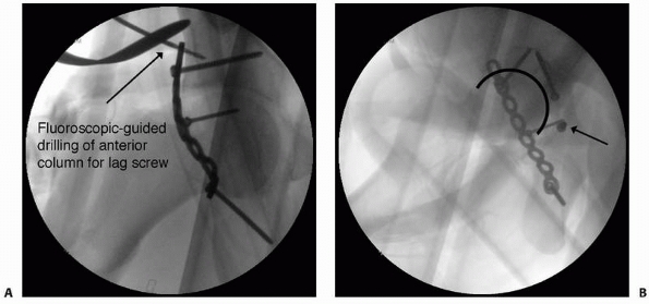
FIGURE 16-1 A.
Intraoperative fluoroscopic anteroposterior view of the pelvis used to evaluate fracture reduction and guide placement of fixation hardware. Here, intraoperative fluoroscopy is used to target drilling of a lag screw across the anterior column component of an associated transverse and posterior wall fracture repaired from a posterior approach. B. Intraoperative imaging is also useful for ensuring that hardware is not within the joint does not extend into the joint space. Multiple views are taken with the C-arm in different positions until the screw of interest is seen “head-on.” With this view, it can then be determined whether the screw penetrates the joint surface. The screw can then be compared with the joint space in profile to evaluate for intra-articular extension. In this case, the screw (arrow) is clearly outside of the joint. |
fluoroscopy are almost universally used during the operative care of
fractures. Imaging techniques are needed during surgery to verify the
reduction of fractures, identify the starting portals for
intramedullary nails, target cannulated or interlocking screws, and
verify implant position (Fig. 16-1).
Fluoroscopic assessment of tibial plateau fracture reduction leads to
results as good as or better than those obtained with
arthroscopy-assisted reduction.111 Norris et al.137
used intraoperative fluoroscopy during the repair of acetabular
fractures and found it as effective as postoperative radiographs to
assess fracture reduction and comparable to postoperative CT to
evaluate for intra-articular extension of hardware. Recent advances in
“minimally invasive” fracture fixation rely even more on the
interpretation of fluoroscopic images99 (Fig. 16-2).
 |
|
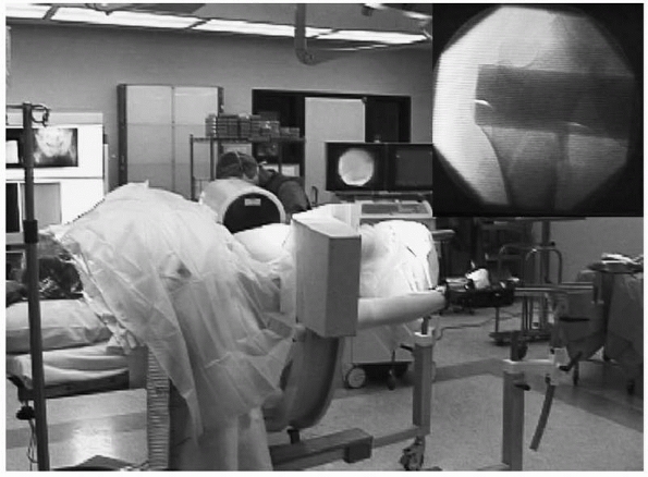
FIGURE 16-2
This intraoperative photograph of a patient in the lateral position for femoral nailing on a fracture table demonstrates the use of fluoroscopy to evaluate fracture reduction and, later, to guide implant positioning. Top right, corresponding fluoroscopic image. |
surgeons insist on obtaining conventional radiographs at the completion
of surgery. Although this practice requires further radiation exposure
and adds time and expense, it is important for both clinical and
medicolegal documentation. Fluoroscopic images have limited
field-of-view and may not demonstrate the full extent of hardware
fixation (as in the case of an intramedullary nail) or overall limb
alignment as well as conventional radiographs. Finally, it may be
difficult to compare intraoperative fluoroscopic images to later
conventional radiographs, so the immediate postoperative radiograph
represents an important baseline reference for future comparisons.
radiation that operating room personnel are exposed to during the care
of fractures when fluoroscopy is used.15,87,170 Fortunately, with modern fluoroscopic systems, measurable radiation exposure is limited to the surgeon’s hands,15,87 although he or she needs to limit excessive use of the fluoroscope during surgical procedures. Recently, Matthews et al.122
showed that during surgery, repetitive fluoroscopic scout imaging is
performed to reproduce a specific desired image. In a simulated
test-rig, an average of seven scout images were required to reproduce a
given C-arm position.122 In
contrast, these investigators showed that the use of
navigation-assisted repositioning using a standard, commercially
available image-guided surgical navigation system did not require a
single additional scout image, with comparable positioning times.122
ability to generate a cross-sectional, computer-reconstructed axial
image in real-time.8,30,90,91,176
C-arms that are adapted for this purpose incorporate a motor that
rotates the x-ray tube and image intensifier around the patient while
taking hundreds of images. Immediate computer processing generates a
reconstructed cross-sectional image that is similar to an axial CT
image. The ability to obtain immediate cross-sectional images during
surgery can help the surgeon assess reduction during the repair of
certain intra-articular fractures when direct visualization of the
articular surface is not possible.30
Cross-sectional intraoperative imaging may also be of benefit in
situations when hardware placement requires precision, such the
insertion of pedicle screws or iliosacral screws. In cadaver models of
calcaneal fracture90 and acetabular fracture,91
three-dimensional (3D) fluoroscopy was superior to standard
two-dimensional (2D) fluoroscopy and comparable to CT for the detection
of intra-articular hardware and intermediate between the other
modalities in demonstrating articular impaction of acetabular fracture91 or the articular reduction or medial screw protrusion in calcaneal fractures.90
In a clinical series of articular fractures, information obtained via
intraoperative 3D fluoroscopy led to a decision to revise the fracture
and/or fixation in 11% of cases.8 In
another series of patients undergoing surgery for foot and ankle
trauma, 39% of cases with adequate conventional C-arm images were
revised intraoperatively after 3D fluoroscopy was performed.156
However, it is important to note that no one has documented that the
use of 3D fluoroscopy improves outcomes, so for now this technology
remains mostly investigational.
navigation techniques may be performed with cross-sectional imaging
data obtained from preoperative CT, fluoroscopy is commonly used for
surgical navigation because of its flexibility, convenience, low
radiation exposure, and low cost. Although the field of surgical
navigation is in its infancy, computer-assisted surgical navigation has
already been applied to cervical and thoracic spine fracture fixation,7 placement of percutaneous iliosacral and anterior column screws in the pelvis,39,73,131 and intramedullary nailing (see Chapter 17).88,94,169
computer-based system, which tracks the position of a hand-held tool in
space. It is necessary to “register” the patient’s bone within the
computer based on preoperative CT data or the use of a generic dataset.
Fluoroscopic views need be taken only once; thereafter, all movements
of the tool are recorded against the registered bone image and may be
displayed in different planes simultaneously, superimposed on the
static images by the computer system. This dramatically reduces the
need for repeated intraoperative imaging, decreasing the time of
surgery and the radiation exposure of the patient and surgical team.
However, intraoperative changes in the patient’s position or in the
dimensions of the registered bone (such as might occur during fracture
reduction) decrease the accuracy of image registration. Surgical
navigation has been used for hip fractures33,109 and placement of iliosacral screws.131
During intramedullary nailing of the femur, surgical navigation
facilitates accurate entry-point location, fracture reduction, and
insertion of interlocking and blocking screws and assists with
determination of nail and screw length.65,94,180 Weil et al.180
used a cadaveric femur model to demonstrate that computerized
navigation may increase the precision of fracture reduction, while at
the same time lessening requirements for intraoperative fluoroscopy. In
another cadaveric model, navigated distal interlocking was found to
lead to less rotational deformity (2 degrees) compared with freehand
distal interlocking (7 degrees).65
the clinical importance and cost-effectiveness of surgical navigation
remain undetermined. Collinge et al.36
compared the safety and efficiency of standard multiplanar fluoroscopy
with those of virtual fluoroscopy for use in the percutaneous insertion
of iliosacral screws in 29 cadaver specimens. Interestingly, both
methods were equally accurate; one screw was incorrectly inserted
in
each group, and both groups contained examples of screws with minor
deviations in trajectory. Although the actual time for screw insertion
was less with virtual fluoroscopy (3.5 minutes versus 7.1 minutes),
this was offset by the increased time needed to set up and calibrate
the image-guided system.36 Liebergall et al.109
showed improved screw parallelism and screw spread when navigation was
used during repair of femoral neck fractures, and this correlated with
fewer reoperations and overall complications in the navigated group.
radiographic imaging modalities; its inventors (Godfrey Houndsfield and
Allan Cormack) received the Nobel Prize for Medicine in 1979. Since its
inception in the early 1970s, advances in technology and computer
science have guided the development of several new generations of CT
scanners, each capable of greater throughput and improved resolution.
Although a more detailed review of the history of CT scanners is beyond
the scope of this section, a brief description of current concepts in
CT scanner technology is presented.
1980s and are so named because of the helical path the x-ray beam takes
through the patient. The development of “slip ring” technology allowed
the gantry (x-ray tube and detectors) to rotate continuously around the
patient, whereas with previous-generation scanners, gantry rotation was
constrained by electrical cables, which needed to be unwound in between
slice acquisitions. With nonhelical scanners, table position was
incrementally advanced in between slice acquisitions; with slip ring
technology, the table position is advanced continuously while the
gantry rotates, resulting in a helical x-ray beam path.
1992, with 4- and 16-slice models appearing in 1998 and 2001. On the
whole, multislice scanners are similar to single-slice helical scanners
in many respects. Instead of a single row of detectors, however,
multiple rows of detectors are present within the gantry and are
designed to allow acquisition of multiple slices at the same time. Now
64-slice CT scanners are clinically available, and 256-slice scanners
are currently under development.
to be modified, which resulted in new terminology and imaging
parameters to adjust. For single-slice helical scanners (and
older-generation scanners as well), slice thickness is determined by
x-ray beam collimation, whereas, for multislice scanners, it is
determined by detector width. For single-slice scanners, pitch is
defined as the ratio of table movement (mm) per 360-degree rotation to
slice thickness (mm). A pitch of 1.0 is comparable to older-generation
scanners where the table movement increment was the same as the slice
thickness. A pitch of less than 1.0 results in overlapping of the x-ray
beam and higher patient radiation dose; a pitch greater than 1.0
results in increased coverage through the patient and decreased
radiation dose. In practice, pitch is generally limited to 1.5 to 2.0,
although protocols vary. For multislice scanners, the definition of
pitch changes to incorporate the detector array width rather than the
single slice width and is referred to as detector pitch.
are both helical in nature, and individual slices must be interpolated
from the data set. Minimum slice thickness is set by the original x-ray
beam collimation (single-slice scanners) or detector width (multislice
scanners). Any number of slices may be reconstructed at any position
along the long axis of the patient, and in any thickness equal to or
greater than the minimal slice thickness. This allows reconstruction of
overcontiguous slices (with typically 50% overlap), which increases the
sensitivity for detecting small lesions that may otherwise be averaged
between adjacent slices. This also results in twice as many images,
although with no increase in scan time or additional radiation dose to
the patient.
reconstructions are also routinely performed with both single-slice and
multislice helical scanners. This, in part, is related to the fact that
today’s CT examinations routinely produce hundreds of images, and MPR
and 3D reformatting assist in interpreting these data. Advances in
detector technology have allowed slice thickness to decrease such that
slice thicknesses of 0.5 mm are routinely achieved clinically and allow
acquisition of isotropic voxels. A voxel is the 3D equivalent of a
pixel and represents the volume of tissue represented by a single
pixel; isotropic voxels have uniform thickness in all directions (e.g.
0.5 mm × 0.5 mm × 0.5 mm). Acquisition of images with isotropic voxels
results in multiplanar (nonaxial) reconstructions that have in-plane
resolutions equal to those of the original axial image. Additionally,
the use of overcontiguous images is useful in 3D reconstructions to
eliminate stair-step artifact.
on standard CT images, which frequently obscures surrounding bone and
soft tissue detail. This streak artifact is propagated on multiplanar
reformatted images as well. Fortunately, volume-rendering of a
multidetector CT axial database can dramatically reduce streak artifact
associated with hardware.60
include faster scan times and patient throughput, reduced motion
artifacts, reduced intravenous contrast requirements, improved lesion
detection, and improved multiplanar and 3D reconstructions.
Disadvantages include the potential for decreased resolution along the
long axis of the patient (related to increased pitch) and a large
number of images, resulting in increased reconstruction time and
storage requirements. Another disadvantage of CT in general is the high
radiation dose associated with this modality. However, radiation doses
can be reduced by using low-dose, rather than standard-dose, scanning
algorithms without differences in subjective image quality evaluation.133
choice for evaluating complex fractures as well as ruling out injury to
the spine. In addition to high-resolution axial images, multiplanar
reconstructions are commonly performed (Fig. 16-3).
Such information provides critical data about the displacement of
fracture fragments, including assessment of intra-articular
displacement, articular surface depression, and bone loss.
Three-dimensional reconstructions using surface rendering techniques
are often less helpful in fracture management compared with multiplanar
reconstructions. With 3D imaging techniques, fracture planes are
frequently obscured by overlying fracture fragments and underestimate
the true degree of comminution;
however,
they may be helpful in evaluating angulation and displacement of
fracture fragments, in addition to depression of articular surfaces.
With previous-generation CT scanners, evaluation of fracture planes
parallel to the scan plane was suboptimal because of volume averaging
of the fracture plane with adjacent intact bone. With newer helical
scanners, image data are obtained as a volume rather than as individual
slices, and multiplanar reconstructions typically have resolution equal
to the axial images. For this reason, detection of transversely
oriented fracture planes is significantly enhanced. Typical indications
for CT include fractures of the proximal humerus, scapula, spine,
pelvis, tibial plateau, tibial plafond, calcaneus, and midfoot.
 |
|
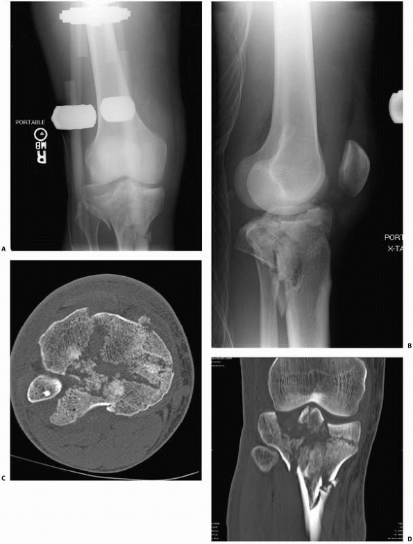
FIGURE 16-3 A, B.
Anteroposterior and lateral views of a complex bicondylar tibial plateau fracture taken after the limb was placed in a spanning external fixator. Axial computed tomography (CT) (C) and two-dimensional reconstructions in the coronal (D) and sagittal (continues) |
 |
|
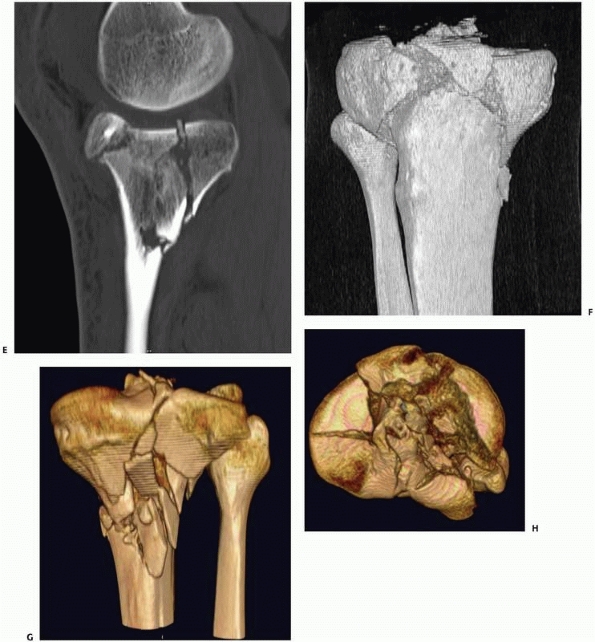
FIGURE 16-3 (continued) (E) planes better demonstrate the extent of comminution. With high-resolution three-dimensional reconstruction (F, G),
a very good appreciation of the fracture pattern is possible. Finally, the tibial plateau can be viewed from “above” by digitally subtracting the femur and patella and rotating the image (H). For complex fractures such as this, advanced CT scanning is unparalleled. |
of choice. A variety of measurements that incorporate CT data have been
described that are useful in the assessment of the cervical spine
following injury, including cervical translation and vertebral body
height loss, canal compromise, spinal cord compression, and facet
fracture and/or subluxation.18 Despite its greater initial expense, CT has been shown to have sensitivity
and specificity of 96%, both greater than for conventional plain radiography.72 Grogan et al.72
present a decision analysis emphasizing cost minimization and conclude
that helical CT is the preferred initial screening test for detecting
cervical spine injury in moderate- to high-risk trauma patients.
Multiplanar reconstructions of complex proximal humeral and scapular
fractures assist in surgical planning. For proximal humeral fractures,
simple axial images provide important information about the
glenohumeral relationship, demonstrate glenoid rim fractures, and
reveal whether the tuberosities of the humerus are fractured. Occult
fractures of the coracoid process and lesser tuberosity are readily
seen.74 Despite the valuable
information that CT provides (with or without multiplanar
reconstructions), several studies have shown that the interobserver
assessment of proximal humeral and scapular neck fractures was not
improved with the addition of CT.124
For distal radial fractures that mandate surgical reconstruction, CT is
more accurate than conventional radiography in demonstrating
involvement of the distal radioulnar joint, the extent of articular
surface depression, and the amount of comminution.35,150
Three-dimensional CT was found to further improve the accuracy of
fracture classification and to influence treatment decisions compared
to standard 2D CT in a series of 30 intra-articular distal radius
fractures.76
For the assessment of acetabular fractures, CT is better than
conventional plain radiography at identifying intra-articular step-offs
and gaps and is considered an essential part of the preoperative
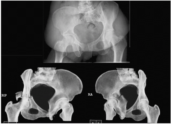
evaluation.19 Reformatted images can be obtained in oblique planes to simulate standard Judet radiographs66 (Fig. 16-4).
Use of CT-reformatting avoids the pain and risk of fracture
displacement or hip redislocation that might occur while repositioning
the patient 45 degrees on each side for Judet views. A potential
disadvantage is the slight loss of information resulting from volume
averaging and computer reconstruction that could affect interpretation
of the images. In an unpublished study, 60 orthopedic trauma surgeons
randomly reviewed sets of pelvic radiographs from 11 patients and were
asked to classify each according to the Judet-Letournal system; each
patient had 2 sets of images (one with traditional Judet radiographs
and one with reformatted CT scans). For 10 of the 11 cases there were
no differences in classification; in the final case of a T-type
fracture, classification was more consistent when the CT-reformatted
images were viewed (personal communication, Rena Stewart, MD).
Postoperative CT after acetabular fracture repair identifies residual
articular defects or incongruities better than plain radiographs.20 CT demonstrates intra-articular debris in a significant number of patients after hip dislocation,82
and CT should be performed in any patient whose conventional plain
radiographs show an incongruent reduction. Because small
intra-articular bodies may not be visible on radiographs, one should
consider obtaining CT images in all patients who sustain a hip
dislocation, even when conventional plain radiographs appear to be
normal.
 |
|
FIGURE 16-4 Computed tomography of the pelvis reformatted in 45-degree right and left oblique planes (bottom)
to simulate the traditional plain film Judet views of the pelvis. The corresponding anteroposterior view is shown above. (Courtesy of Dr. Rena Stewart.) |
conventional radiographs for formulating a treatment plan, the mean
interobserver kappa coefficient was 0.58, which increased to 0.71 after
adding CT. The mean intraobserver kappa coefficient for fracture
classification using radiographs was 0.70, which increased to 0.80 with
addition of CT. The mean intraobserver kappa coefficient for treatment
plan based on radiographs alone was 0.62, which increased to 0.82 after
adding CT. With the addition of CT, the fracture classification was
changed in 12% of cases, whereas the treatment plan was altered 26% of
the time.32 In another study, Wicky et al.183
compared helical CT with 3D reconstructions to conventional radiography
in patients with tibial plateau fractures and found that, for the
purpose of classification, fractures were underestimated in 43% of
cases by radiographs. Among a smaller subset of patients in whom
operative plans were formulated with and without CT, the same
investigators found that the addition of helical CT 3D reconstructions
led to modifications in the surgical plan in more than half the cases.183
evaluated the use of preoperative CT in the management of tibial pilon
fractures. Twenty-two patients were studied with both conventional
radiographs and CT. The fracture pattern, number of fragments, degree
of comminution, presence of articular impaction, and location of the
major fracture line were recorded. CT revealed more fragments in 12
patients, increased impaction in 6 patients, and more severe
comminution in 11 patients. The operative plan was changed in 14 (64%)
patients, and additional information was gained in 18 (82%) patients.174
 |
|
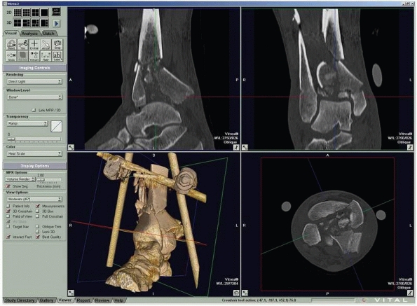
FIGURE 16-5
Computed tomography of a triplane fracture as viewed on a digital workstation. Users can visualize axial and reconstructed coronal and sagittal images simultaneously. |
CT reveals bone debris in the subtalar joint of patients with lateral
process fractures of the talus.53 In
children with Tillaux fractures of the anterolateral distal tibia, CT
is better than conventional radiography in detecting displacement of
more than 2 mm, which is considered an indication for surgery81 (Fig. 16-5). Helical CT is valuable for the preoperative planning of calcaneal fractures.61
Axial images of the calcaneus best show hindfoot deformity, whereas
multiplanar reconstructions (including 3D imaging with dislocation of
the joint) best reveal intra-articular involvement.61
compared the functional outcome of 67 patients with posterior wall
acetabular fractures with the findings on postoperative CT. In this
study, postoperative CT more accurately revealed the degree of residual
fracture displacement compared with conventional radiographs, and the
accuracy of surgical reduction seen on postoperative CT was highly
predictive of the clinical outcome.127 Vasarhelyi et al.175
found side-to-side torsional differences of greater than 10 degrees in
one-quarter of 61 patients undergoing fixation of distal fibula
fractures.175 Kurozumi et al.102
correlated postoperative radiographs and CT with functional outcomes in
67 patients with intra-articular calcaneal fractures and found that
better reduction of the calcaneocuboid joint and posterior facet of the
subtalar joint correlated with improved outcome.
Healing
of Fractures. Conventional radiographs are often limited in
demonstrating persistent fracture lines, and such nonunions are more
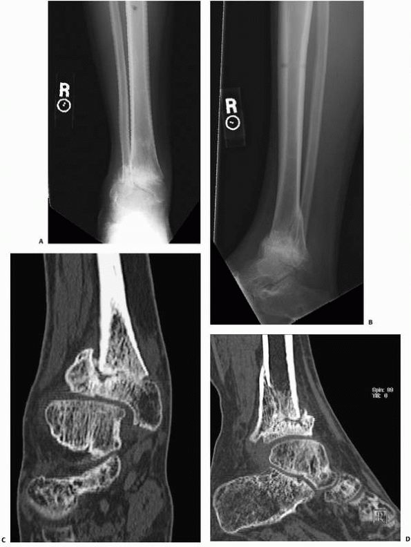
readily demonstrated on CT13 (Fig. 16-6).
CT has replaced conventional tomography in most centers for the
identification of fracture nonunions. Multiplanar CT reconstructions
may be needed if the fracture pattern is complex. Assessing partially
united fractures can also be difficult, even with CT. The accuracy of
CT in detecting tibial nonunion was evaluated. Bhattacharyya et al.13
studied 35 patients with suspected tibial nonunion and equivocal plain
radiograph findings. In this series, the sensitivity of CT for
detecting nonunion was 100%, but its accuracy was limited by a low
specificity of 62%, because three patients who were diagnosed as having
tibial nonunion by CT were found to have a healed fracture at surgery.13
fracture healing. CT reveals external callus formation earlier than
conventional radiography and allows for more complete and detailed
visualization of fracture healing, which may be obscured by overlying
casts and/or fixation hardware on radiographs.71 Lynch et al.116
developed a means of measuring changes in CT density at fracture sites
by quantifying the formation of mineralized tissue within fracture
gaps, while ignoring loss of bone mineral caused by disuse
osteoporosis. In a preliminary study of seven patients with distal
radial fractures, this technique demonstrated increased CT density 2
weeks postfracture that correlated with the visual appearance of
sclerosis and blurring of the fracture line on conventional radiographs.116 It is not yet known whether such information will be predictive of fracture healing complications.
radiofrequency (RF) waves, in the presence of a strong magnetic field,
to interact with the patient’s hydrogen atoms (protons) to create
images of superb soft tissue contrast. Although the physics of MRI is
complex and too detailed to review in this section, the more practical
aspects of MRI relevant to the evaluation of orthopaedic imaging will
be discussed.
field strength. The basic unit of measurement of magnetic field
strength is the Gauss (G); the earth’s magnetic field measures
approximately 0.5 G. Field strengths for MRI are much greater and are
measured in Tesla (T), which is defined as 10,000 G. Low-field-strength
scanners are typically 0.2 to 0.3 T and are commonly used in outpatient
settings as “extremity” or “open” scanners. High-field-strength
scanners are generally those greater than 1.0 T, with 1.5-T scanners
dominating the market and representing more than 90% of installed
scanners worldwide. The 3.0-T scanners have also become clinically
available, although their acceptance has been limited because of the
higher cost of these systems and relatively limited selection of
receiver coils. Advantages to higher-field-strength scanners include
increased capability, increased resolution and image quality, and
decreased scan time.
RF coils are used to transmit RF waves into the patient, as well as
receive RF signals (“echoes”) from the patient during the course of the
examination. A standard “body” coil is incorporated into scanners as a
default coil from which to both send and receive RF signals. The body
coil is located within the housing of the magnet and, as a result, is
located some distance from the patient. This distance factor decreases
the strength of the RF signal received from the patient, although this
is not a problem for imaging larger body parts such as the abdomen and
pelvis. For smaller body parts, such as extremities in orthopaedic
imaging, specialized RF coils are available and are widely used to
increase the quality of MRI studies. These coils are usually “receive
only” coils, meaning the body coil transmits the RF pulse; some
specialty coils, however, incorporate both transmit and receive
functions. These smaller coils are placed around or over the body part
to be scanned, which decreases the distance from the patient’s anatomy
to the coil and results in greater signal return from the underlying
tissue. This increases the signal-tonoise ratio (SNR) of the resulting
images and produces images of greater contrast resolution and higher
image quality, which may be used to improve image quality, increase
spatial resolution, or decrease scan time.
variety of RF coil designs available today. Volume coils encircle the
anatomy of interest and provide increased signal homogeneity. Surface
coils are placed over the anatomy of interest and significantly improve
near-field signal strength returning from the underlying anatomy.
Quadrature and phased-array coil designs incorporate multiple coil
elements with electronic coupling to increase signal strength and SNR.
Specialized coils are available for orthopaedic imaging and include
dedicated phased-array coils, as well as various sizes of flexible
surface coils.
refers to sequence of radiofrequency pulses that are applied in concert
with a series of magnetic gradients. These pulses are applied in a
particular order and with a particular timing scheme, with the RF coils
listening for the resulting “echoes” at specific time intervals. Pulse
sequences determine the type of image contrast produced. During each
pulse sequence, magnetic gradients are applied to the main magnetic
field to achieve spatial localization. A magnetic gradient along the
long axis of the bore of the magnet (and patient) is used for slice
selection, whereas gradients along the transverse plane are responsible
for frequency and phase encoding, which result in localization within
the transverse plane. Most MRI examinations are particularly loud as a
result of rapidly switching the gradients on and off, which
necessitates use of earplugs or headphones during the test study.
Inherent in all pulse sequences are specifications for parameters such
as geometry (imaging plane, field of view, number of slices),
resolution (number of frequency and phase encoding steps, slice
thickness), and image contrast (repetition time [TR], echo delay time
[TE]). A collection of multiple pulse sequences used for a particular
examination is often referred to as a protocol.
spin-echo (SE) and gradient-echo (gradient recalled echo [GRE])
imaging. Spin-echo sequences are most frequently used in conjunction
with a fast imaging technique, termed fast spin-echo (FSE) or turbo
spin-echo (TSE) imaging, depending on the manufacturer. Spin-echo
sequences provide T1-weighted (T1W), proton density (PD), and
T2-weighted (T2W) image contrast based on selection of the parameters
TR and TE. T1W images tend to depict anatomy well and are sensitive,
but not specific, for pathology. T2W images are fluid-sensitive images
and tend to depict pathology well. PD images are neither T1W
nor
T2W, and contrast is derived from differences in proton density within
the tissues. PD images are commonly used in orthopaedic imaging, as
they result in high SNR images and depict anatomy and pathology well.
PD images are often acquired in conjunction with T2W images during the
same pulse sequence; in this case, the PD image is referred to as the first echo, and the T2W image is called the second echo. This combination may also be referred to as a double echo (DE, 2E) sequence.
 |
|
FIGURE 16-6 A, B.
Anteroposterior and lateral radiographs of a patient who had external fixation of a distal tibia fracture with progressive deformity. C, D. Computed tomography of the nonunion with two-dimensional reconstructions in the coronal and sagittal planes provides unambiguous evidence of fracture nonunion. |
fluid, is relatively bright on PD and T2W sequences. Fat suppression
(FS) techniques are necessary to evaluate for edema or fluid with
fat-containing tissues, such as bone marrow. Two techniques are
commonly used: short TI inversion recovery (STIR) and chemical
saturation (“fat-sat,” spectral saturation, frequency-selective
presaturation). STIR is a distinctive spin-echo pulse sequence that
results in suppression of a particular tissue based on the choice of an
additional parameter, TI. A relatively short TI value of 150 ms results
in suppression of fat-containing tissues. This sequence tends to be
relatively low in SNR and, as a consequence, is often performed at
lower resolution. The sequence is less affected by variations in
magnetic field homogeneity, however, and results in fairly uniform fat
suppression throughout the image. Chemical saturation is a
frequency-selective RF pulse, which is applied before the normal RF
pulse, and effectively eliminates the signal from fat-containing
tissues. This may be applied to any of the spin-echo sequences (T1W,
PD, T2W); T1W FS sequences are typically used after contrast
(gadolinium) enhancement, whereas PD FS and T2W FS sequences are used
in evaluating a variety of tissues, including bone marrow and articular
cartilage. Chemical saturation is often used in conjunction with
lower-resolution FSE sequences, as the technique decreases SNR as a
result of eliminating fat signal, resulting in “grainier” images at
higher resolutions. Chemical saturation is also sensitive to
inhomogeneities in the external magnetic field, which may result in
nonuniform fat suppression across the field of view. This is
particularly a problem with extremities positioned off-center with the
bore of the magnet, such as the elbow, where the magnetic field is not
as uniform compared with isocenter. When uniformity of fat suppression
is a problem, STIR images may be substituted. STIR images are not
sensitive to gadolinium and cannot be used to evaluate
gadolinium-contrast enhancement, and hence are less useful for MR
arthrography or intravenous contrast studies.
challenging task that involves balancing tradeoffs in signal (SNR),
spatial resolution, contrast resolution, and image acquisition time.
Low SNR images tend to be “noisy” or “grainy” and unpleasant to view.
Higher-resolution techniques result in both lower SNR and longer
acquisition times and may not be practical for all patients; for this
reason, lower resolution techniques may be required. Many patients are
unable to tolerate long scan times because of pain and limitations on
movement during the examination, and, motion artifact may become a
problem. MR artifacts (wrap around, motion artifact, pulsation
artifact, metallic artifact) represent additional sources of image
degradation and can be difficult at times to eliminate. Newer
modifications of existing pulse sequences are available on high-field
MR scanners to reduce metallic artifacts associated with orthopaedic
implants. When difficulties arise during an MRI examination, pulse
sequences often need to be modified to obtain the information needed
from the examination.
and soft tissue injury after trauma. It is capable of defining
fractures that are radiographically occult, pediatric articular
fractures, and associated soft tissue injuries that may not be
suspected or evaluable after physical examination and plain
radiography. Although MR angiography is a well-established technique
for noninvasive evaluation of the arterial system, it may be
impractical for evaluating the multitrauma patient. Evaluation of
vascular trauma is accomplished much more rapidly with CTA or
conventional angiography, which also allows for interventional
procedures (e.g., embolization of arterial bleeding). A more
controversial application is MR venography (MRV) to detect deep venous
thrombosis (DVT) of the proximal thigh and pelvic veins. In a recent
review of the imaging of deep vein thrombosis, Orbell et al.138
note that MRV has many advantages, including lack of exposure to
ionizing radiation and avoidance of any need for vein cannulation and
injection of contrast (for nonenhanced studies). MRV is as sensitive
and specific for proximal leg DVT as ultrasonography (US) or venography29 and is reported to be more accurate in the detection of isolated pelvic thrombi.129 Unfortunately, the cost and logistical problems of MRI have limited its usefulness in the imaging of DVT.
However, the practicality of using MRI in trauma patients may be
limited by difficulties associated with transporting patients to the
MRI suite, as well as MRI incompatibilities with various life-support
equipment and patient implants. MRI scan times are also much longer
than with CT and other imaging modalities and may not be tolerated by
potentially unstable patients or those in considerable pain. Thus, for
practical reasons, MRI continues to have only a limited role in the
immediate management of the trauma patient.
possible to quantitatively assess bone structure and function, so that
MRI may someday supplant bone densitometry as a tool to assess fracture
risk caused by osteoporosis as well as the response to treatment.179
It is now well known that bone marrow edema (bone bruise, bone marrow
contusion) is frequently identified on MRI after extremity trauma.
Histologically, these imaging findings correlate with cancellous bone
microfractures as well as edema and hemorrhage within the fatty marrow.153 The long-term sequelae of these radiographically occult lesions have not been well defined. Roemer and Bohndorf159
evaluated 176 consecutive patients with acute knee injuries and found
that nearly three fourths had bone marrow abnormalities. The majority
of lesions (69%) involved the lateral compartment of the knee; 29% were
medial, and 2% were patellofemoral. Many of the lesions resembled edema
of the subchondral bone, without other osseous or cartilage injury,
while nearly one fourth represented subchondral impaction fractures and
one third comprised osteochondral or chondral lesions. Forty-nine of
these patients had repeat MR studies conducted at least 2 years after
their injury. In these patients, only 7 of 49 (14%) had persistent
signal changes within the marrow space. The extent of signal
abnormality was less than originally seen, and none of the patients
developed degenerative changes, regardless of the injury type that was
initially present. No cases of posttraumatic osteonecrosis
were
found. Therefore, one must be careful to avoid interpreting marrow
signal abnormalities alone on MRI as evidence of a true fracture, as
this may lead to overtreatment. This distinction is especially
problematic in the assessment of hip pain after a fall, where
trochanteric bone marrow edema might be interpreted as a fracture,
leading to a decision to perform internal fixation.
occult fractures. Fracture lines are distinctly visualized on PD or T2W
images as linear, lower-signal intensity abnormalities silhouetted by
higher-signal intensity marrow fat. Fracture lines can also be seen on
STIR and PD/T2W FS images, which also show the degree of surrounding
reactive marrow edema. Care is needed in interpreting T1W images;
however, images as fracture lines may be obscured by surrounding marrow
edema, both of which are hypointense in signal intensity on T1W images.67
identifying occult fractures for which correct early diagnosis is
essential, such as femoral neck fractures110,115 (Fig. 16-7), scaphoid fractures,46,100,152,160 and pediatric elbow injuries.151
In elderly patients with hip pain after a fall, early MRI when
radiographs are normal can avoid delays in diagnosis and treatment of
hip fractures. In one study, 25 patients with hip pain were evaluated
for occult fracture with conventional radiographs, scintigraphy, CT, or
a combination of studies.148 A final
diagnosis was ultimately determined from repeat radiographs in 10
patients and by scintigraphy in 15 patients. The time to final
diagnosis averaged 9.6 days when the diagnosis was made by serial
radiographs and averaged 5.3 days when the diagnosis was made by
scintigraphy. Given the delay in diagnosis associated with using more
conventional methods of imaging, the authors point out that use of
immediate MRI instead can dramatically decrease the number of imaging
examinations performed and the time to diagnosis, resulting in
decreased costs of care and possibly reduced complications.148 In a more recent study, six elderly patients with hip pain after a fall had both MRI and CT, while seven others had MRI alone.115 In the first group, four of the six CT studies were inaccurate, while all MRI studies correctly defined the pathology.115
In cases of occult hip fracture, the fracture pattern can be delineated
using MRI, which may be of therapeutic importance. Occult fractures of
the femoral neck that frequently are treated with screw fixation may be
distinguished on MRI from occult intertrochanteric fractures, greater
trochanter fractures, or pubic rami fractures that do not require
surgical stabilization. Finally, if the MRI does not demonstrate
fracture, it often does indicate another finding that explains a given
patient’s symptoms.62 Clinicians may
be more apt to rely on MRI alone than on NM studies; in one report,
clinicians always requested additional imaging for cases in which the
bone scan was positive.43 MRI may also identify additional comorbid conditions such as preexisting osteonecrosis or metastatic disease.75
pediatric elbow injuries. In one series, seven of nine pediatric
patients with an elbow effusion after injury were found to have a
radiographically occult fracture.151
In the same series, MRI provided further useful diagnostic information
in 16 other patients despite the presence of a visible fracture and/or
dislocation of the elbow on plain radiographs.151
modality of choice for imaging complex fractures, recent studies
indicate that MRI may be valuable in the assessing such injuries as
well. In one such study, the impact of MRI on the treatment of tibial
plateau fractures was assessed.187
Patients presenting with tibial plateau fracture were assessed with
conventional radiography, CT, and MRI. Three sets of images were
prepared for each injury: radiographs alone, radiographs with CT, and
radiographs with MRI. Three surgeons were asked to determine the
fracture classification and suggest a treatment plan based on each set
of images. The investigators found that the best interobserver
variability for both fracture classification and fracture management
was seen with the combination of conventional radiographs and MRI. The
Schatzker classification of tibial plateau fractures based on
conventional radiographs changed an average of 6% with the addition of
the CT and 21% with the addition of MRI. MRI changed the treatment plan
in 23% of cases. Holt et al.80
studied 21 consecutive patients with tibial plateau fractures who were
evaluated with both conventional radiography and MRI before treatment.
MRI was more accurate in determining fracture classification, in
revealing occult fracture lines, and in measuring the displacement and
depression of fragments. The MRI findings resulted in a change in the
classification of 10 fractures (48%) and a change in the management of
four patients (19%). MRI also allowed diagnosis of associated
intra-articular and periarticular soft tissue injuries preoperatively.
spinal trauma, but MRI is increasingly being used to evaluate for
associated injuries such as herniated discs with cervical spine
injuries and possible spinal cord injury associated with thoracolumbar
spine fracture/dislocations. Green and Saifuddin70
have shown that 77% of patients with spine injury have a secondary
injury level identified by whole spine MRI. Most commonly, these
secondary injuries were bone marrow contusions, but 34% of patients had
noncontiguous compression or burst fractures diagnosed by MRI.
contrast resolution and good spatial resolution, MRI provides an
accurate means to assess soft tissue injury. MRI of the shoulder and
knee is commonly ordered for evaluation of tendons, ligaments, and
cartilage after trauma, frequently related to athletic injuries. Common
indications for shoulder MRI following trauma include evaluation of the
rotator cuff tendons for tearing, the superior glenoid labrum for
superior labral anterior-posterior (SLAP) tears, and the anteroinferior
labral-ligamentous complex after glenohumeral joint dislocation.11,37,172
Standard indications for knee MRI following trauma include evaluation
of the cruciate and posterolateral corner ligaments for sprain or
disruption, the menisci for tears, and the articular cartilage for
osteochondral injury.50,63,182,184 Lonner et al.112
compared MRI findings to examination under anesthesia in 10 patients
with acute knee dislocations who had later surgical intervention, at
which time the pathology was defined. Although the investigators
considered MRI to be useful for defining the presence of ligamentous
injuries in knee dislocations, the clinical examination under
anesthesia was more accurate in this series when correlated with
findings at surgery.112
assessing intra-articular derangement in many joints. Common
indications include distinguishing partial- from full-thickness rotator
cuff tears and evaluating labral-ligamentous pathology
in
the shoulder, evaluating the collateral ligaments in the elbow and the
intercarpal ligaments in the wrist, demonstrating labral tears in the
hip, evaluating postoperative menisci in the knee, assessing stability
of osteochondral lesions, and delineating intra-articular bodies.167
Direct MR arthrography is performed by intra-articular injection of a
dilute gadolinium solution, resulting in distention of the joint
capsule and improved delineation of intra-articular structures.
Indirect MR arthrography is performed using intravenous injection of
gadolinium, with a delay before scanning during which mild exercise may
be performed. The indirect technique is based on recognition that the
intravenous gadolinium diffuses from the highly vascular synovium into
the joint space. The indirect technique does not produce controlled
joint distention, however, and is best applied in smaller joints such
as the elbow, wrist, ankle, and shoulder.12
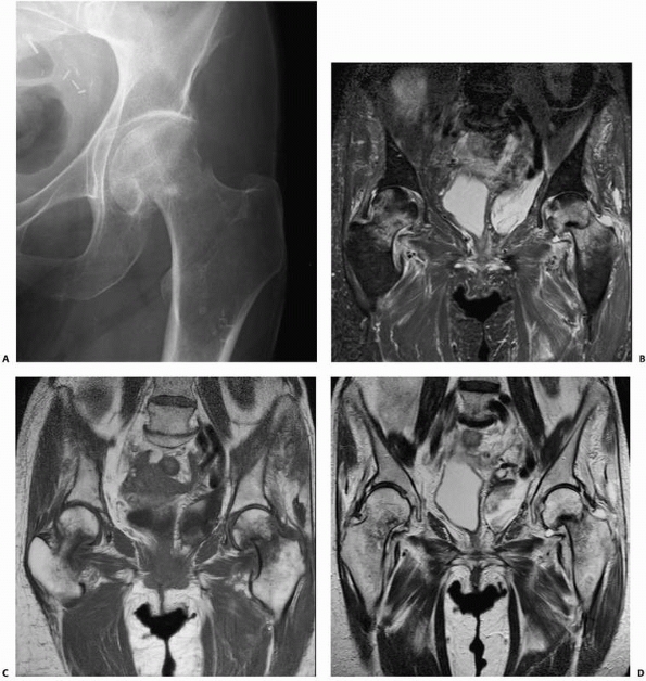 |
|
FIGURE 16-7 A.
Conventional plain anteroposterior radiograph of a patient’s hip demonstrates a femoral neck fracture. Although the fracture can be seen on routine radiographs, the patient was at risk for osteonecrosis because of corticosteroid use related to a kidney transplant. Some apparent changes are seen in the bone density of the femoral head. Magnetic resonance imaging of the pelvis confirms the presence of an acute left hip fracture and demonstrates that there was no osteonecrosis. Incidentally noted is a small developing fracture with surrounding stress reaction in the right femoral neck medially: (B) STIR, (C) T1-weighted, and (D) T2-weighted images. Higher-resolution images of the left hip fracture demonstrating mild impaction at the fracture site without significant angulation. (continues) |
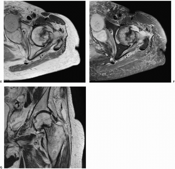 |
|
FIGURE 16-7 (continued) Axial proton density (E), axial fat-suppressed proton density (F), and coronal T2-weighted (G) images. Note inferior pole of kidney transplant in the lower left pelvis with surrounding complex fluid collection.
|
challenge in MRI because metal distorts the magnetic field and results
in large areas of signal void, which frequently obscures adjacent
anatomy. Modifications of traditional MR pulse sequences have been
developed on high-field MR scanners to reduce artifact associated with
orthopaedic implants. FSE (turbo) sequences are used, which inherently
decrease metallic artifact compared with routine SE and GRE sequences.
Modifications to FSE sequences include increasing receiver readout
bandwidths, decreasing interecho spacing and reducing effective echo
times to maintain SNRs.165 These
protocols are now commonly found in the sequence libraries of many
newer MR scanners. Protocols based on modification of receiver
bandwidth have been shown to reduce metallic artifact by an average of
60%, whereas additional experimental protocols (not commercially
available) using a combination of several susceptibility artifact
reduction
techniques further reduce metallic artifact by an average of 79%.98
The degree of artifact is also dependent on the metallic composition of
the orthopaedic hardware, with titanium generally exhibiting the least
amount of artifact. Applications for these sequences include evaluation
of painful joint replacements, particularly knee and hip prostheses,149,164,165 and osteonecrosis of the femoral head after pinning femoral neck fractures (Fig. 16-8).
may experience linear force, torque, and heating. In general, most
contemporary orthopaedic implants are not ferromagnetic and are MRI
compatible in terms of heating and migration. Most fracture implants
are made of 316L stainless steel, titanium, or titanium alloy; none of
these materials contain delta ferrite, so they are not magnetic.44
MRI can be safely performed about plates, screws, and total joint
implants, although artifacts may degrade the image as described
earlier. In contrast, some external fixator components, especially
clamps, contain strongly ferromagnetic materials and can be potentially
unsafe in an MRI scanner.41,101 Davison and colleagues41
studied 10 sets of commercially available tibial external fixators that
they applied to sawbone tibia. The external fixators were tested for
magnetic attraction using a hand-held magnet while positioned 30 cm
outside the entry portal of a 1.5-Tesla scanner, at the level of the
entry portal, and 30 cm inside the MRI tube. The EBI Dynafix with Ankle
Clamp, EBI Dynafix, and EBI Dynafix Hybrid, along with the Hoffman II,
Hoffman II Hybrid, Ilizarov with stainless steel rings, and Synthes
Hybrid, all had more than 1 kg of magnetic attraction at all three
locations, which is a significant enough force to cause potential
movement of implant and pain. These devices were not scanned. Three
devices—the Ilizarov fixator with carbon fiber rings, Richards Hex-Fix,
and Large Synthes External Fixator—had less than 1 kg of magnetic
attraction at all three locations and were scanned for 30 minutes while
temperature measurements were obtained with a digital thermometer and
thermocouple. No component of these three fixators experienced more
than 2°F of temperature elevation during a 30-minute MRI scan. Davison
et al.41 conclude that many
commercially available external fixators have components that have
significant magnetic attraction to the MRI scanner. Fixators that have
less than 1 kg of attraction do not experience significant heating
during MRI.
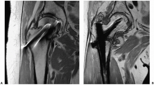 |
|
FIGURE 16-8 Metal artifact reduction sequences. A.
A femoral neck fracture after pinning with four screws demonstrates nonunion. Magnetic resonance imaging using metal artifact reduction sequences shows no evidence of avascular necrosis of the femoral head. B. An additional case of nonunion of an intertrochanteric fracture that demonstrates avascular necrosis of the femoral head without subchondral fracture or collapse. The intramedullary rod and screw are titanium, which results in fewer artifacts than stainless steel or other alloys. |
recently studied new MRI-compatible large external fixator clamps made
by Synthes and found dramatic reductions in forces experienced in a 3-T
field compared with older devices. All orthopedic surgeons should check
with the manufacturer and be aware of the MRI compatibility of their
particular external fixator inventory.
distention of a joint capsule using positive or negative contrast
agents. Water-soluble, iodinated contrast media is typically used to
provide positive contrast, whereas air has been historically used to
produce negative contrast. Double-contrast examinations may also be
performed using both agents simultaneously, although these techniques
are largely of historical interest, as advances in cross-sectional
imaging have supplanted double-contrast arthrography techniques.
a 22-gauge needle is used for larger joints, including the shoulder,
hip, and knee, and a 25-gauge needle is used for smaller joints, such
as the elbow, wrist, ankle, and smaller joints of the hands and feet.
The anatomic approach varies according to each joint; for example, a
lateral approach into the radiocapitellar joint space is frequently
used for the elbow, and anterior approaches are typically used for the
shoulder, hip, and tibiotalar joint. Table 16-2
lists technical considerations for arthrography of selected joints.
After needle placement, small amounts of contrast are injected until
the intra-articular location of the needle tip is confirmed. Contrast
is then injected with subsequent distention of the joint capsule; the
amount also varies by joint.
fluoroscopy, and sequential spot films are obtained before and during
the injection to evaluate the flow of contrast. Pathology is inferred
by abnormal communication of contrast with extracapsular structures.
Passive and active range of motion are often required to demonstrate
pathology, as abnormalities may only be shown after contrast is allowed
to work its way through defects in the capsule and into the surrounding
soft tissues. Contrast extravasation through capsular abnormalities can
be fairly rapid and may occur during passive or active range of motion.
Extravasation may also occur during periods when the fluoroscope is not
energized. In addition, the fluoroscope only provides 2D views of bony
anatomy, and it is extremely limited in its evaluation of surrounding
soft tissues. Consequently, localizing the site of extravasation during
conventional arthrography can be quite challenging. Care is also needed
to avoid overdistention of the joint capsule, as extravasation through
the capsule can occur, leading to subsequent decompression of
intra-articular contrast and possible false-positive interpretations.
include bleeding and infection at the injection site, in addition to
allergic reactions related to iodinated contrast media. A small number
of patients experience postprocedural pain, possibly related to a mild
synovial inflammatory response to the contrast media. Although patients
are generally apprehensive about the procedure, they generally tolerate
the procedure with less discomfort than expected.158
|
TABLE 16-2 Arthrographic Techniques of Selected Joints
|
||||||||||||||||||||||||||||
|---|---|---|---|---|---|---|---|---|---|---|---|---|---|---|---|---|---|---|---|---|---|---|---|---|---|---|---|---|
|
digital imaging, digital subtraction techniques have been developed for
fluoroscopy. Typically, a preliminary scout film serves as a “mask,”
which is subsequently subtracted from images following contrast
injection. This significantly improves contrast resolution of the
fluoroscopic spot films and enables visualization of contrast that
would otherwise be inapparent when adjacent to similar high-density
objects, such as joint prostheses. Digital subtraction arthrography
(DSA) also allows sequential injection and evaluation of adjacent joint
compartments, as a new mask is obtained after injection of the first
compartment, which is subsequently subtracted from images acquired
during injection of the second compartment. DSA techniques are
sensitive to patient motion, however, which produces misregistration
artifact as a result of misalignment of the mask and subsequent images.
DSA also requires specialized equipment, which may not be available
outside of radiology departments.
as CT and MRI, have largely replaced conventional arthrography for
evaluating internal derangement, but these imaging modalities may be
combined with arthrography using appropriate contrast agents for each
modality.58,167
For CT arthrography (CTA), an arthrogram is first obtained using a
contrast solution containing saline and water-soluble, iodinated
contrast media, typically in a 1:1 dilution. Thin-section CT is then
performed through the joint, and images in orthogonal planes are
reconstructed. For MR arthrography, a very dilute gadolinium solution
(typically 1:200 dilution) is injected into the joint, and MRI is
subsequently performed. In addition to routine sequences, fatsuppressed
T1W images are used to visualize the injected contrast. With both
imaging modalities, evaluation is aided not only by silhouetting
intra-articular structures by relatively bright contrast but also by
distention of the joint capsule. This results in separation of
intra-articular ligaments and capsular structures and allows more
precise evaluation of complex anatomy (Fig. 16-9).
Bony and soft tissue abnormalities are directly visualized with these
cross-sectional techniques, compared to conventional arthrography,
whereby pathology is inferred based on the appearance of the contrast
collection in relation to the bony landmarks.
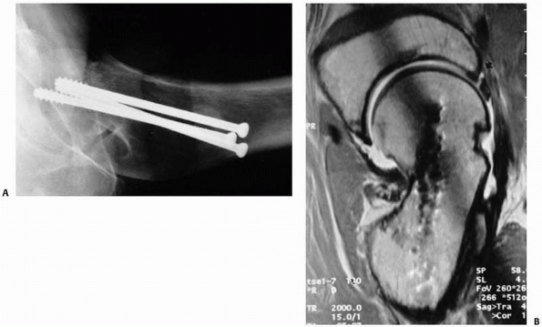 |
|
FIGURE 16-9 A.
Lateral radiograph of the proximal femur after fixation of a femoral neck fracture, showing malunion with retroversion of the femoral neck. B. The patient had persistent hip pain, and magnetic resonance arthrography revealed a tear of the anterior acetabular labrum. Note angular deformity at the site of fracture malunion and residual micrometallic artifact related to insertion of prior screws. (Reprinted with permission from Eijer H, Myers SR, Ganz R. Anterior femoroacetabular impingement after femoral neck fractures. J Orthop Trauma 2001;15:475-481.) |
arthrography was traditionally used for assessing periarticular soft
tissue injuries associated with trauma. Today, there are more limited
indications for arthrography, although it is frequently performed in
combination with CT and MRI to increase the sensitivity and specificity
for internal derangement.
contraindications to MRI, such as pacemakers or intracranial aneurysm
clips. CTA is preferred, however, as advances in CT scanner technology
have led to marked improvements in resolution and scan time, resulting
in high spatial resolution images and multiplanar reconstructions of
intra-articular structures.
arthrography may be performed to evaluate for full-thickness rotator
cuff tears. Extravasation of contrast into the subacromial/subdeltoid
bursa is diagnostic of a full-thickness tear. Even with careful
fluoroscopic observation during the injection process, it is frequently
impossible to delineate the site or extent of the tear, as contrast
medium may accumulate in the bursa without visualization of an obvious
tract through the torn tendon. Occasionally, no extravasation is seen
after completing the injection; however, after passively and/or
actively exercising the shoulder, subsequent fluoroscopy reveals
contrast flooding the bursa as a result of the medium working itself
through a full-thickness tear. Special care is needed in interpreting
arthrography of the postoperative rotator cuff, because intact cuff
repairs may continue to leak contrast into the bursa.
Arthrography has historically been applied to the evaluation of ulnar
collateral ligament injuries of the thumb (“gamekeeper’s thumb”).
Recent literature has shown MR arthrography to be more accurate in
detecting ulnar collateral ligament injuries and in evaluating
displacement of the torn ligament.1
alone is rarely performed for trauma but may be combined with CT or MRI
for evaluating osteochondral abnormalities113 (Fig. 16-9).
A recent study comparing CTA with MR arthrography suggests that CTA may
be more accurate in evaluating cartilage lesions of the ankle joint.161
performed posterior subtalar joint arthrography at a mean of 6 months
postinjury in 22 patients; 15 had undergone surgical repair and 7 had
been treated nonoperatively. The patients were separated into four
groups based on arthrographic findings: normal, narrow, irregular, and
ankylosis. Clinical follow-up performed at a mean of 23 months
postinjury correlated very well with the earlier arthrographic
findings, suggesting that subtalar arthrosis is responsible for much of
the symptoms that develop after calcaneal fracture.
that are not visible on conventional radiographs. It is also used
intraoperatively to assist with the reduction of pediatric radial head
fractures.86 The use of arthrography
to assess pediatric injuries has been largely supplanted by MRI (when
available), although in the pediatric population both procedures may
require sedation.
Klein et al.96
compared MRI with arthrography and CTA for the diagnosis of wrist pain
in 346 patients. Imaging findings were correlated with surgical
findings in 78 of these patients and with the clinical course in the
remainder. Because of its ability to perform functional imaging,
arthrography was the best method for evaluating scapholunate ligament
tears and defects of the ulnolunate and ulnotriquetral ligaments.
of sound waves with frequencies greater than 20 kHz (20,000 Hz), which
are beyond the audible range of the human ear. Typical frequencies used
in medical diagnostic US range from 2.0 to 12 MHz, although frequencies
of 20 MHz and higher are in clinical use for more specialized
applications involving very small regions of anatomy. Lower frequencies
within this range (2 to 5 MHz) allow deeper penetration of the US beam
for evaluation of thicker body parts, although at lower spatial
resolutions. Higher-frequency US beams (10 to 12 MHz) provide greater
spatial resolution and are frequently used in evaluating superficial
anatomy, such as tendons.
piezoelectric materials to convert electrical energy into mechanical
energy (sound waves). Today’s transducer designs are complex and may
incorporate hundreds of individual piezoelectric elements, each of
which is energized in turn or in combination, such that the individual
sound waves combine into an US beam. The US beam propagates into the
underlying tissues and is partially reflected back at tissue boundaries
because of differences in acoustic impedance between tissues. Acoustic
impedance is defined as the product of tissue density and the speed of
sound, both of which vary among tissues. Small differences in acoustic
impedance will produce smaller reflections of sound waves, whereas
large differences in acoustic impedances will result in larger
reflections. The reflected echoes travel back to the transducer, where
the transducer elements convert the sound waves into electrical
signals, which are then used to create the US image.
corresponding to a tissue element at a particular depth and location.
Echoes returning from underlying soft tissue elements are generated
from reflections of the US beam at tissue interfaces of different
acoustic impedance. In addition, smaller cellular elements within
tissues can also act as individual “scatterers.” Each of these
scatterers reflects a small portion of the US beam in all directions. A
portion of these scattered echoes are reflected back toward the
transducer and are displayed in the image as background “echogenicity”
that is characteristic for that tissue. Echoes returning from
superficial soft tissues have shorter round trip distances to travel
back to the transducer and are detected earlier than those for deeper
soft tissues. For this reason, the depth of a tissue element can be
calculated using the return time of its corresponding echo. The
amplitude of the returning echo determines the brightness, or
echogenicity, of a tissue element. As the US beam travels deeper within
the soft tissues, it progressively loses energy and subsequent echoes
from deeper tissue elements are smaller in amplitude. A correction
factor, termed time gain compensation, is
applied to deeper soft tissues to account for this drop off in echo
amplitude. Thus, differences in echogenicity in the resulting US image
will be less dependent on tissue depth and more related to differences
in acoustic impedance and scattering.
burst of US waves (the US pulse) into the underlying tissues, and then
listens for the returning echoes. The time spent sending out the US
pulse is a tiny fraction of the listening time, typically about 0.5% of
the total cycle time. The pulse repetition frequency determines how
many pulses are sent into the underlying tissue over time, and
typically ranges between 2000 and 4000 cycles/s (2 to 4 kHz). During
routine scanning, the transducer is constantly steering and refocusing
the US beam within the underlying tissue to generate echoes that will
correspond to each pixel in the US image. The two-dimensional US image
that is generated is typically referred to as B-mode (“brightness” mode) imaging.
The designs of current transducers are quite complex and rely on
advanced electronics and scanning algorithms, but have resulted in
greater spatial resolution and more advanced feature sets, including
3D, four-dimensional, and Doppler imaging.
to describe the relative brightness of echoes returning from tissues or
tissue interfaces. Tissues may be described as hypoechoic or hyperechoic with regard to a reference tissue, in addition to isoechoic if two distinct soft tissues share the same level of echogenicity. The descriptor anechoic
refers to a tissue or medium that produces no reflected echoes and is
black on the corresponding US image. Water is the best example of an
anechoic medium, because all of the sound waves are transmitted through
the medium without any reflections. In such situations, the energy
within the US beam will be greater as it reaches the tissues on the far
side of the medium and the distal tissues will appear brighter; this is
referred to as increased through transmission.
Conversely, any tissue or medium that blocks transmission of all sound
waves will appear highly echogenic at its proximal interface with the
US beam and will exhibit “distal acoustic shadowing,” whereby the more
distal tissues appear black, resembling a shadow. Cortical bone and air
are examples where the large differences in acoustic impedance result
in marked attenuation of the US beam, producing distal acoustic
shadowing.
quality of the examination can be influenced by the sonographer’s
training, experience performing certain examinations, and understanding
of normal anatomy and disease states. US is a real-time examination,
and although images that represent the underlying anatomy are saved,
these two-dimensional images cannot provide the depth of understanding
that real-time visualization provides. For this reason, it may be
necessary for the interpreting physician to be present or to image the
patient to interpret complex examinations.
tissues, such as blood flow within vessels. Velocity measurements and
directions of flow may be ascertained based on frequency shifts of the
returning echoes. When the US beam is reflected from a tissue moving
toward the transducer, the returning echoes undergo a slight increase
in frequency. Similarly, when interacting with a tissue moving away
from the transducer, the US beam will be reflected such that the
returning echoes will incur a slight decrease in their frequency. These
frequency shifts are used to calculate the speed of the moving tissue,
whereas the
direction of frequency shift (positive versus negative) is used to determine the direction of motion relative to the transducer.
today’s scanners and are frequently used for vascular evaluation.
Duplex Doppler imaging combines 2D B-mode imaging with pulsed Doppler
imaging; the 2D B-mode image provides an anatomical map to identify
vessels for subsequent Doppler interrogation. Color Doppler combines
B-mode grayscale imaging with color flow superimposed over vessels, as
determined by Doppler imaging. Shades of red and blue are assigned to
the vessels based on their velocities and directions and represent flow
toward and away from the transducer, respectively. Power Doppler
imaging is a signal-processing algorithm that uses the total amplitude
of the Doppler signal to generate maps of flow, which are then
superimposed on B-mode grayscale images. The corresponding images
demonstrate greater sensitivity to slow flow, although no directional
information is available.
imaging modality that is now widely available in most hospitals and in
many clinics. Diagnostic US has an established role in the immediate
diagnosis of trauma patients according to the ATLS protocol, where it
is used in the “Focused Abdominal Sonography for Trauma” examination
for intra-abdominal injury. US also has applications in evaluation of
fractures, fracture healing, soft tissue trauma including ligamentous
injury, and venous thromboembolism.
used US to assess the reduction of pediatric forearm fractures in the
emergency department, thereby avoiding multiple trips to the radiology
suite while gaining much more rapid assessment of the quality of
fracture reduction. In some centers, US is used to rule out
intra-articular elbow fractures.92
Assessing pediatric elbow injuries is notoriously difficult because of
the complex joint anatomy and the multiplicity of its ossification
centers, many of which are relatively unossified in childhood. US has
proved to be valuable in evaluating lateral condylar fractures, in that
it is able to assess the extent of the fracture line through the
unossified capitellum and trochlea, to distinguish unstable
intra-articular fractures from their stable extra-articular
counterparts.177
in settings where conventional radiography may not be readily
available, such as in military or aerospace settings.95 Dulchavsky et al.51
prospectively evaluated 158 injured extremities by US. Nonphysician
cast technicians, who had received limited training and were blinded to
the patient’s radiographic diagnoses, performed the US evaluations.
Examinations only required an average of 4 minutes and accurately
diagnosed injury in 94% of patients with no false-positive results.
Injuries that were diagnosed by US included fractures in the upper arm,
forearm, femur, tibia/fibula, hand, and foot.
performed sonographic evaluation of patients 6 and 12 weeks after
unreamed tibial nailing and found that persistent nail visualization
indicated poor callus formation and predicted later healing
complications. Color Doppler sonography has been shown to demonstrate
progressive vascularization of fracture callus and predict delayed
callus formation in another study of patients with tibial fractures.31
diagnosing musculoskeletal soft tissue injuries and is of proven value
in the assessment of many tendon injuries, such as those of the
tendoachilles, rotator cuff, and ankle.16,28,34,157
US has been used to assess muscle injury, depicted as a tear or
hematoma and subsequent complications such as fibrosis, cystic lesions,
or heterotopic ossification.144 US
is valuable in localizing foreign bodies within soft tissues; an
advantage over conventional radiography is that foreign objects do not
need to be radiopaque to visualize them.108
All trauma patients are at risk for developing deep vein thrombosis
(DVT), and venous US has become the most widely used imaging modality
for DVT diagnosis. In fact, the Intersocietal Commission for the
Accreditation of Vascular Laboratories now mandates duplex Doppler US
as the primary instrument for peripheral venous testing.85
Venous scanning performed by skilled operators is the most practical
and cost-effective method for assessing DVT of the proximal and distal
lower extremity veins. Several US modalities are used to evaluate DVT,
including B-mode for real-time visualization of compression of larger
veins.
and color Doppler for depicting patency of veins are particularly
useful in the calf and iliac veins.189
The diagnostic accuracy of US is well documented, and the sensitivity
and specificity of venous US (including all types) for the diagnosis of
symptomatic proximal DVT is 97% and 94%, respectively.189
The high specificity of venous US is sufficient to initiate treatment
of DVT without further confirmation, and the high sensitivity for
proximal DVT makes it possible to withhold treatment if the examination
is negative.189 When US examinations
cannot be performed (e.g., uncooperative patient, presence of bandages,
casts), an alternative diagnostic procedure, such as contrast
venography, may be needed. More advanced imaging modalities, such as CT
or MR venography are also available. US is less accurate in the
diagnosis of proximal DVT involving the pelvis; MR venography has been
suggested as a more accurate modality for detecting intrapelvic DVT.129
radiopharmaceutical with subsequent imaging using a gamma scintillation
camera. The radiopharmaceutical is typically composed of two moieties:
a radionuclide and a pharmaceutical compound. The pharmaceutical is
responsible for localization of the molecule in the body, and the
radionuclide allows imaging of the pharmaceutical distribution.
spontaneous decay, which results in the emission of photons. Photons
that are generated in the nucleus of the atom are gamma rays,
whereas
photons generated by electron transitions within their orbital shells
are x-rays. Either may be used for imaging, although the particular
choice of a radionuclide predetermines the types and energies of
photons that are emitted. In many NM imaging applications, technetium (99mTc)
is commonly used as the radionuclide because of its favorable imaging
properties (140 keV gamma energy), clinically suitable half-life (6
hours), availability (99Mo/99mTc generator) and ease in labeling of pharmaceuticals. Other radionuclides used in orthopaedic imaging include gallium (67Ga) and indium (111In) and are discussed later in this section.
are designed to localize to target tissues once injected intravenously.
There are many different mechanisms of localization, but for
orthopaedic imaging, regional blood flow is important for all
administered radiopharmaceuticals. Specific radiopharmaceuticals for
orthopaedic imaging and their method of localization are discussed
later in this section.
that capture photons within a large flat crystal, commonly made of
sodium iodide activated with thallium. Photons interact with the
scintillation crystal and are converted to visible light, which is then
captured by photomultiplier tubes (PMTs) coupled to the crystal. The
PMT converts the light photon into an electrical signal, which is
subsequently amplified and electronically processed. This process
results in a single “count” in the final NM image corresponding to a
single radioactive decay in the patient.
camera over the anatomy of interest and accumulating counts for a
specific amount of time or for a minimum number of counts, typically on
the order of hundreds of thousands of counts. Imaging is often
performed after a delay to allow localization and/or uptake of the
radiopharmaceutical within the target tissues. Delayed imaging
demonstrates characteristic patterns of distribution throughout the
body for a particular radiopharmaceutical, in addition to abnormal
accumulation or absence of activity corresponding to disease states.
Consequently, nuclear imaging studies are based on visualization of
metabolic function, rather than anatomy. Anatomic features are
frequently visualized on NM images, although spatial resolution is
typically quite poor compared with other imaging modalities (Table 16-1).
scintillation camera is left stationary in a single projection,
resulting in a planar image. Single-photon emission computed tomography
(SPECT) is an extension of planar imaging, whereby the gamma camera
rotates around the patient, stopping at predefined intervals, to
acquire multiple static planar images. Using techniques similar to
those in CT, these planar data sets are then processed by computers.
Images are typically created in orthogonal tomographic planes (axial,
coronal, sagittal), in addition to 3D volumes. Although the main
advantage of SPECT over planar images is the improved image contrast
resolution as a result of eliminating radioactivity from overlapping
anatomy, spatial resolution is similar or slightly decreased compared
to planar imaging (Table 16-1).
by introducing artifacts into the diagnostic image. Hardware can shield
the gamma camera from photons arising behind the hardware, resulting in
a photopenic defect. Knowledge of indwelling hardware and their
characteristic photopenic appearances alleviates misinterpretation of
these defects. Multiple projections are also frequently performed
during a single examination, which allows evaluation of the activity on
multiple sides of the hardware.
diphosphonate, which localizes to bone based on chemiadsorption of the
phosphorus compound to the mineral phase of bone, particularly at sites
of increased osteoblastic activity. Regional blood flow is also
important for tracer distribution, as areas of increased regional blood
flow deliver greater tracer to the adjacent skeleton, and result in
greater uptake. The term bone scan typically refers to images obtained after a 2- to 4-hour delay, to allow localization of the diphosphonate compound. Three-phase bone scans
incorporate additional dynamic and immediate imaging phases. A
radionuclide angiogram (first phase) is obtained during transit of
radiopharmaceutical through the arterial system. Immediate static
images are then obtained for an additional 5 minutes (second phase) and
represent “blood pool” or “tissue phase” images. Both of these earlier
imaging phases are used to evaluate for regional hyperemia, as
evidenced by both increased blood flow and increased surrounding soft
tissue uptake.
of the skeleton, with slightly greater uptake in the axial skeleton
(spine, pelvis) than the extremities. In skeletally immature
individuals, there is normal avid uptake in the growth plates,
resulting in symmetrically increased bands of activity occurring
adjacent to joints and apophyses. Many diseases are characterized by
both increased osteoblastic and osteoclastic activity within the bone,
in addition to regional hyperemia, and result in greater tracer uptake
(“hot” lesions) than normal bone. These abnormalities may be solitary
or multiple, and focal or diffuse in nature. Some pathological
processes, particularly permeative processes (small round cell tumors)
or those that elicit little surrounding bone reaction, result in
regions of decreased tracer uptake, or “cold” lesions. These lesions
may be difficult to detect on routine bone scans. Bone scans are highly
sensitive for disease processes, although specificity is poor. A normal
bone scan may rule out underlying skeletal abnormality, but a positive
bone scan necessitates further workup of the underlying abnormality.
sulfur colloid. The sulfur colloid is composed of particles measuring
between 0.1 and 2.0 µm, which are taken up by the reticuloendothelial
cells within the liver (85%), spleen (10%), and bone marrow (5%).
Uptake is rapid (half-life is 2 to 3 minutes), and imaging is performed
after a 20-minute delay. Current indications for marrow imaging are
limited but include evaluation of osteomyelitis in conjunction with111In-labeled white blood cell imaging.
radiopharmaceutical that was originally developed as a bone-imaging
agent but was later found to be useful in imaging infection and
inflammation. After intravenous injection, gallium binds to transferrin
and
circulates
in the bloodstream. At sites of inflammation or infection, increased
regional blood flow and increased vascular permeability result in
greater accumulation of gallium. In addition, neutrophils release large
amounts of lactoferrin as a part of their inflammatory response;
gallium has a higher binding affinity for lactoferrin than transferrin
and localizes at the site of inflammation. Gallium is a relatively poor
imaging agent, as its photons are not optimum for imaging with
present-day gamma cameras, and total body clearance is slow with
considerable background activity. Imaging is typically performed at 48
hours, which contributes to delays in diagnosis.
evaluation of osteomyelitis. Gallium activity that is greater than, or
in different distribution than, corresponding activity on the bone scan
is diagnostic for osteomyelitis.
for using labeled white blood cells (WBCs) for diagnosing infection
and/or inflammatory processes. Of these,111In oxine- and
99mTc-labeled hexamethylpropyleneamine (HMPAO)-labeled WBCs are discussed briefly.
lipid-soluble complex that readily crosses the cell membranes.
Approximately 50 mL of blood must be withdrawn and the leukocytes need
to be separated from the plasma and red cells. Labeling is accomplished
by incubating the leukocytes with the111In
oxine complex for 30 minutes. The leukocytes are then resuspended in
plasma and reinjected into the patient within a total of 2 to 4 hours.
Imaging is typically performed at 24 hours to allow for leukocyte
localization and clearance from the blood pool.
that also crosses cell membranes and may be used to label WBCs,
preferentially granulocytes. Approximately 50 to 75 mL of blood is
withdrawn and incubated with the radiopharmaceutical; however, the
labeling process is performed in plasma, and cell separation is not
needed. The labeled cells are then reinjected, and imaging is performed
at 4 hours for the peripheral skeleton.
with sulfur colloid marrow studies for evaluation of osteomyelitis and
infected joint replacements. When used alone, labeled white cell
studies may result in false-positive results, because labeled WBCs
normally distribute to the bone marrow, in addition to the liver and
spleen, after reinjection. The sulfur colloid marrow study is used to
map out areas of normal residual marrow activity. Congruent activity is
seen within the bone marrow on both examinations. Osteomyelitis results
in replacement of marrow activity on the sulfur colloid study,
resulting in a photopenic defect, whereas there is significantly
increased activity on the corresponding labeled WBC study.
when conventional radiographs are normal or to evaluate the
significance of abnormalities seen on radiographs. Although typically
highly sensitive for disease processes, its poor specificity makes it
necessary to correlate the findings with additional clinical history,
laboratory evaluation, or imaging examinations. Applications of NM to
orthopaedic trauma include evaluation of fractures, osteomyelitis, and
osteonecrosis.
demonstrated positive scans in 80% of fractures at 24 hours, and in 95%
by 72 hours. Advanced age and debilitation contributed to
nonvisualization of fractures beyond this time frame. The minimum time
to return to normal was 5 months, and 90% of fractures returned to
normal by 2 years. Because of its poor specificity, scintigraphy can
lead to false-positive diagnoses of fracture. Garcia-Morales et al.64
reported five cases of false-positive scans for hip fracture because of
collar osteophytes; subsequent MRI in these patients was negative.
insufficiency fractures are also well delineated on bone scintigraphy
as focal areas of increased radiotracer uptake. Characteristic sites of
stress fractures depend on the activity that produced them, although
there is considerable overlap. Some fracture patterns show
characteristic appearances on scintigraphy. For example, in elderly
patients with chronic low back or hip pain, sacral insufficiency
fractures reveal a classic “H” pattern of uptake, known as the “Honda”
sign.143 Not uncommonly, several
focal areas of increased tracer uptake are seen in the skeleton, which
presumably represent a combination of acute and more chronic findings.
In these cases, three-phase scintigraphy can provide additional
information regarding hyperemia and may help to differentiate acute
from chronic injuries. Typically, hyperemia resolves within 4 to 8
weeks after initial injury, with the blood flow, then the blood pool,
images normalizing.
in 40 patients with tibial shaft fractures that were treated
nonsurgically. Using the normal leg as a control, an activity index
(the ratio of the uptake counts of the injured leg to the normal leg)
was calculated. All fractures in this series healed within 20 weeks and
the activity ratio index progressively decreased at the three
evaluations.10 The investigators
speculate that a persistently increased activity index would indicate
future development of healing complications, such as delayed union or
nonunion, although they did not have any such healing complications in
their series.10
with nonaccidental trauma. In a study from Australia, studies of 30
children who were the victims of suspected child abuse and who had both
skeletal surveys and bone scintigraphy were retrospectively reviewed.118
Excluding rib fractures, there were 64 bony injuries, of which 33% were
seen on both imaging modalities, 44% were seen on skeletal survey only,
and 25% of the injuries were seen on bone scans alone. Metaphyseal
lesions typical of child abuse were found in 20 cases (31%) on skeletal
survey; only 35% of these were identified on bone scan. The
investigators believed that both skeletal survey and bone scintigraphy
should be performed in cases of suspected child abuse.
spread of microorganisms to bone, from direct extension from areas of
adjacent soft tissue infection, or as a result of open fractures and/or
surgery. Persistent pain or delayed healing after surgery can be
difficult to evaluate with regard to infection, as conventional
radiographs may show only more advanced destructive changes and MRI may
be very difficult to interpret in light of recent surgery.
to imaging orthopaedic infections. In addition to three-phase bone
scans, dual gallium/bone scintigraphy and labeled WBC studies,
including combination leukocyte/bone and leukocyte/marrow studies, are
valuable in diagnosing both acute and chronic osteomyelitis as well as
infected joint replacements. No one study is equally applicable to all
clinical situations, however.141
for detecting osteomyelitis in normal underlying bone, the specificity
of this test is markedly reduced in the presence of underlying bone
disease.
scintigraphy has been used to evaluate osteomyelitis. Gallium
scintigraphy demonstrates greater accuracy (86%) in diagnosing spinal
osteomyelitis compared with111In-labeled WBCs (66%).140 A recent evaluation of imaging techniques in spinal osteomyelitis and surrounding soft tissue infections has recommended SPECT67Ga
as the radionuclide study of choice when MRI is unavailable or as an
adjunct in patients with possible spinal infection in whom the
diagnosis remains uncertain.114 Gallium is also better suited for imaging of chronic osteomyelitis compared with 99mTc HMPAO-labeled WBCs, which are better for imaging acute infections.146
high sensitivity (97.7%) and specificity (96.8%) for acute
osteomyelitis, although its sensitivity for chronic osteomyelitis is
slightly decreased.185
99mTc HMPAO-labeled WBC scintigraphy is preferred for
evaluating children because the radiation dose to the spleen is smaller
and less blood is needed for labeling.162 99mTc HMPAO-labeled WBC scintigraphy is superior to 99mTc bone scintigraphy for children younger than 6 months because of the poor sensitivity of bone scintigraphy at this age.146111In-labeled WBC scintigraphy is preferred in evaluating chronic osteomyelitis, as dual111In WBC/99mTc SC studies result in improved accuracy for diagnosis of osteomyelitis in regions containing active bone marrow.146,162 In more complex regions with overlapping bone and soft tissues, such as the skull and hips, simultaneous111In WBC/99mTc bone SPECT imaging has been recommended.162
The sensitivity, specificity, positive and negative predictive values,
and accuracy of this approach were 86%, 84%, 69%, 94%, and 82%,
respectively.
 |
|
FIGURE 16-10
Pinhole bone scintigraphy (anteroposterior views) showing a photon-deficient area centrally in the right femoral head and increased uptake in the femoral neck and subcapital area compared with normal left hip findings. (Reprinted with permission from Yoon TR, Rowe SM, Song EK, et al. Unusual osteonecrosis of the femoral head misdiagnosed as a stress fracture. J Orthop Trauma 2004;18:43-47.) |
antigranulocyte monoclonal antibodies has shown a sensitivity of 81%
and specificity of 77% in the diagnosis of osteomyelitis. The authors
conclude that antigranulocyte scintigraphy can be used as a major
diagnostic method in patients with suspected osteomyelitis but cannot
replace traditional methods such as histological examination and cell
culture.139
demonstrate the vascularity of bone, it is often used to try to assess
the risk of osteonecrosis after an injury. Although largely supplanted
by MRI, bone scanning can be used to identify osteonecrosis of the
femoral head before it is apparent on conventional radiographs17 (Fig. 16-10). Studies by Drane and Rudd47 and Mortensson et al.130
have shown that bone scintigraphy cannot predict the risk of
osteonecrosis after femoral neck fracture., Subsequent work has
suggested that SPECT imaging may be more accurate in assessing
vascularity of the femoral head in fractures of the femoral neck.27
angiography are well established and involve cannulation of a vessel,
commonly a major artery, for subsequent diagnostic and therapeutic
interventions. Typically, the right common femoral artery is accessed,
although less common access sites include the left common femoral
artery, the axillary and brachial arteries, and translumbar aortic
approaches, the selection of which depend on the clinical situation and
goal of angiography. The Seldinger technique, the standard procedure
for cannulating the common femoral artery, involves placing an 18-gauge
needle into the artery at the level of the midfemoral head under
fluoroscopic guidance. A double wall puncture is preferred, whereby the
needle is advanced through both the anterior and posterior arterial
walls until contact is made with the femoral head. The needle tip is
pulled back slowly until it is within the arterial lumen and pulsatile
flow is observed from the needle hub. A guidewire is then passed
through the needle and into the vessel
lumen,
and the needle is then exchanged over the guidewire for a catheter or
sheath. Selective catheterization of individual vessels involves
advancing the guidewire into the arterial tree, with subsequent
advancement of the catheter over the guidewire.
catheter tip proximal within the artery of interest and rapidly
injecting nonionic iodinated contrast medium, the rate and volume of
which are proportional to the size of and flow within the vessel lumen.
Rapid fluoroscopic spot filming is timed to coincide with contrast
opacification of the arterial tree and documents progressive filling
and washout of the vessels. Venous return may also be demonstrated with
appropriate delays in filming. Abnormal findings associated with
vascular trauma include transection, laceration, dissection,
arteriovenous fistula, pseudoaneurysm, mural hematoma, intimal tears,
and vasospasm.
technique, whereby a preliminary fluoroscopic spot film (the “mask”) is
taken before contrast injection and is subsequently subtracted from
dynamic images obtained during contrast injection. The background
tissues (bones, soft tissues) are removed from the dynamic arterial
images, resulting in greater image contrast resolution. The
concentration of iodinated contrast may be reduced using this
technique, resulting in a lower total volume of injected contrast
medium. Disadvantages of this technique include lower spatial
resolution and misregistration artifact, which occurs as a result of
patient motion after the mask image has been performed and results in
misalignment of the mask during subtraction.
angiography and, for trauma patients, most commonly include
embolization of bleeding arterial vessels in association with both
visceral and bony fractures. Superselective catheterization of the
bleeding vessel is first performed, with subsequent occlusion of the
vessel using agents administered through the catheter. Temporary and
permanent embolic agents are available, and their use is directed by
the clinical situation and therapeutic goal. Temporary agents include
autologous blood clots and Gelfoam pledgets, whereas permanent agents
include microcoils and macrocoils, detachable balloons, polyvinyl
alcohol, as well as various tissue adhesives and glues. Preembolization
and postembolization angiograms are performed not only to document
occlusion of the bleeding vessel but also to evaluate for collateral
flow around the occluded vessel.
complications (e.g., groin hematoma, arteriovenous fistula,
pseudoaneurysm), contrast complications (e.g., anaphylactoid reactions,
renal failure), catheter-related complications (e.g., vessel wall
dissection, thromboembolism), and therapy-related complications (e.g.,
tissue necrosis distal to embolization). Complications may be reduced
with experience and careful technique by the angiographer.
a relatively new application of multislice helical CT technology.
Intravenous nonionic iodinated contrast medium is injected, usually
through an antecubital vein, using a volume of 120 to 150 mL at a rate
of approximately 3 to 4 mL/s. Scanning is performed after an
appropriate delay to ensure passage of contrast through the lungs and
heart and into the arterial tree, so that imaging occurs during peak
intravascular enhancement throughout the arterial segment of interest.
Technical factors such as beam collimation and pitch are adjusted to
ensure adequate coverage and acceptable scanning times, while
preserving high resolution of the study. Images are typically
reconstructed from the helical dataset at 1.0-mm slice thicknesses with
a 50% overlap. Because a typical CTA study generates hundreds to
thousands of images, evaluation of the data is performed using 3D
workstations, whereby the images may be viewed using cine modes,
multiplanar reconstructions, and interactive real-time volume-rendering
techniques. In addition to arterial injury, concomitant complex
fractures are well evaluated on the same study.
recently, CTA are important diagnostic and therapeutic modalities in
trauma patients with hemodynamic instability because of severe
abdominal and pelvic trauma or extremity injuries with vascular damage (Fig. 16-11).
Although management of a hemodynamically unstable patient with a pelvic
fracture remains controversial, many experts suggest emergent
angiography in these situations.45
The yield in terms of identifiable arterial injury is low; however,
when vascular injury is present, embolization using interventional
techniques can be life saving. If necessary, pelvic angiography can be
performed concomitantly with external fixation of the pelvis in
patients with severe “openbook” injuries of the pelvic ring (Fig. 16-11).
simple and effective means of assessing possible vascular injury of the
pelvis and extremities. CTA of the pelvis can be easily and
successfully incorporated into standard CT evaluation protocols in
patients with blunt trauma and is capable of differentiating active
arterial and venous bleeding that can be useful information in guiding
further care.5 In a study of 48
trauma patients, contrast-enhanced CT was compared to formal
angiography in detecting pelvic bleeding; CT had 94.1% sensitivity and
97.6% negative predictive value for the detection of active hemorrhage,
and 92.6% sensitivity and 91.2% negative predictive value for
predicting need for surgical or endovascular intervention.123
the assessment of popliteal artery injury in the patient with definite
or suspected knee dislocation. Recently, several studies have clarified
the role of angiography in such patients, showing that urgent
angiography is not needed unless there are deficits in distal pulses,
ideally quantified by determination of the anklebrachial index.97,166
assessment of potential vascular injury in the lower extremity because
of its noninvasiveness and immediate availability. At some trauma
centers, CTA has supplanted arteriography for initial radiographic
evaluation of peripheral vascular injuries.145 Inaba et al.84
used multislice CTA in 59 patients who underwent a total of 63 studies.
In their series, multislice CTA was both 100% sensitive and 100%
specific for detecting clinically significant arterial injury.84 A recent study by LeBus and Collinge103
suggests that routine use of CTA in the evaluation of patients with
high-energy tibial plafond injuries may be beneficial. Twenty-five
consecutive patients were treated with a standard protocol that
included preoperative CT (and CTA). In 13 of the patients (52%),
notable arterial injury was identified, most involving
the
anterior tibial artery. The authors thought that information about
associated vascular injury allowed them to make better decisions about
surgical tactics to be used for a given procedure, including whether to
use traditional open or minimally invasive approaches, as well as in
choices about placement of incisions.103
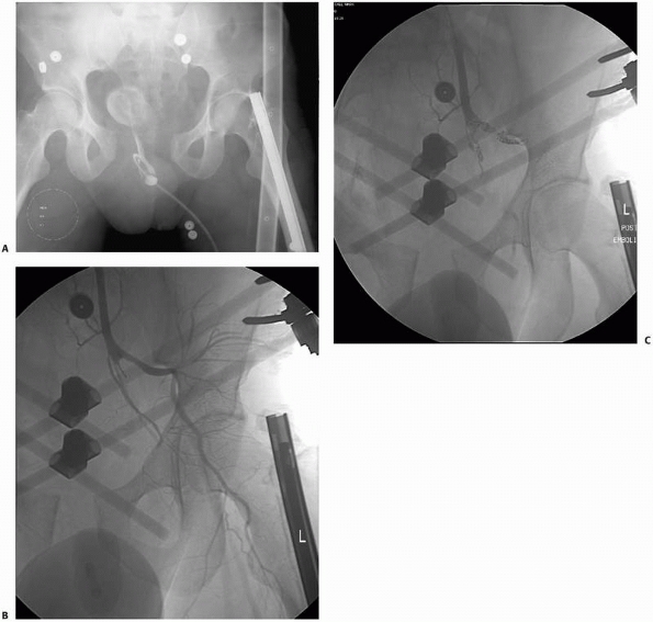 |
|
FIGURE 16-11 Pelvic angiography in a hemodynamically unstable trauma patient with a pelvic ring injury. A.
The anteroposterior pelvic radiograph shows wide diastasis of the pubic symphysis. After emergent application of an anterior pelvic external fixator, the patient underwent selective embolization of both right and left internal iliac arteries. B. Spot film of the left internal iliac artery demonstrates dissection and nonfilling of multiple medial branches. Contrast fills the left internal iliac artery and its branches before embolization. C. Postembolization spot film demonstrates no flow of contrast distal to the embolization coils. |
been paralleled by advances in distributing, viewing, and storing
imaging data. In many instances, the traditional light box has been
replaced by digital workstations, the file room has been upgraded with
digital archives, and the transport of films has been replaced by
digital transmission of images across networks to remote workstations.
Many of these changes have evolved in response to the increasing size
of digital imaging studies, in addition to the need to use and
distribute this information more efficiently within the health care
environment. All of these changes have relied on continued improvements
in computer networks, workstations, storage devices, and display media,
in addition to implementation of standards, to support the evolving
digital imaging infrastructure. Although a thorough discussion of
digital image management is beyond the scope of this section, a brief
review of some of the more common concepts and standards will be
presented.
infrastructure, and clinical needs by interpreting and referring
physicians. Current trends in digital imaging technology have resulted
in greater image resolution and greater numbers of images, both of
which substantially contribute to increasing sizes of imaging studies.
For example, a typical 256 × 256 matrix image, using 2 bytes of storage
for each pixel, requires approximately 125 KB of storage per image,
whereas a 512 × 512 matrix image requires approximately 500 KB, or four
times as much as its lower-resolution counterpart. CT and MRI studies
routinely contain 100 to 200 images, resulting in storage requirements
of 12 MB to 100 MB per study. Newer 64-slice and 256-slice CT scanners
may result in data files of up to 2.5 and 10 GB, respectively, per
study.
Although many imaging departments are transitioning to filmless
environments, sheet films are commonly printed and may be necessary
outside of the imaging department, such as in private clinics and
offices, in addition to the operating room. In particular, hardcopy CT
scans and specific radiographic views must remain available to the
orthopaedic trauma surgeon to use in the operating room when dealing
with complex injuries such as intra-articular fractures and pelvic ring
or acetabular fractures. CD-ROM products are increasing in popularity,
although computer access is necessary to read them and a greater level
of sophistication is needed to use these products. Patients referred
for trauma care from other institutions now often arrive with all of
their imaging studies archived onto a CD-ROM. A frustrating problem for
clinicians is the numerous proprietary software programs that have
evolved for viewing images on a CD-ROM. All too often, the “viewer”
embedded within a CD will not open on a given computer, and even when
it does, the user is often not familiar with the software and can have
problems viewing the images. Images stored on a CD-ROM are highly
compressed and are of poor quality when enlarged to standard viewing
size on a monitor. Institutions with available resources can scan such
images into their picture archive and communications system (PACS) so
that they are available to all, but the inability to do this in a
timely fashion, especially outside normal working hours, can compromise
patient care and require studies to be repeated at the receiving
hospital.
transmitting image data to remote locations for image viewing and
storage, to which the term teleradiology
applies. There is a wide variety of network configurations, with
descriptors such as local or wide area networks (LAN, WAN), intranets,
and the Internet. Speed of transmission across networks depends on the
various types of communication links within the network (modem, ISDN,
DSL, cable modem, T1, T3, fiberoptic cable), as well as the level of
network traffic. Data compression is used to decrease the size of
imaging studies before electronic transmission, and compression schemes
are categorized as “lossless” (no loss of original data, typically 3:1
compression) or “lossy” (some loss of data in original image, typically
15:1 or greater compression). Use of the Internet to transmit imaging
studies is growing, although patient confidentiality and security
issues have received considerable attention.
commonly viewed on workstations, which are able to display images at
full resolution using specific formats (“hanging protocols”) and
provide advanced capabilities for image processing (Fig. 16-5).
Such workstations allow 3D images to be manipulated and reviewed in
real-time; some can save movie files of the 3D image onto a disk. Of
course, such capabilities are of limited value if they are not
available to the orthopaedic trauma surgeon in a timely manner.
Current, high-end workstations are expensive and are usually not
available outside of the radiology department; normally,
less-sophisticated viewing stations provide basic access to images
outside of the imaging department. In certain environments, use of
hardcopy images will remain necessary. Examples of this situation
include the operating room, where multiple images of different imaging
modalities need to be viewed together by a surgeon in sterile operating
garb, and in the clinic, where the viewing of multiple studies in
chronological order is necessary to observe fracture healing or changes
in fracture alignment.
acquire, view, and store digital images and at its most basic level
includes devices used to acquire digital images (e.g., CT and MRI
scanners), workstations whereby images may be viewed and manipulated
for diagnostic interpretations, and archives where digital images are
stored for later retrieval. PACS may also include viewing stations for
departments outside of the radiology department (e.g., emergency
department, intensive care unit), and may be contained within their own
LAN or exist as a part of a larger WAN. PACS may also communicate with
Radiology Information Systems and Hospital Information Systems to share
and/or modify patient information.
access to clinical images, postprocessing of image data (window levels,
multiplanar and 3D reconstructions, measurement and annotations tools),
the ability of more than one user to simultaneously view the same
images, and reduced filming costs and lost films. On the other hand,
significant disadvantages include initial and recurring expenses
related to installing and maintaining PACS, massive storage
requirements for image archival, and the necessity of support personnel
to maintain the network and its components. One study showed that LCD
personal computer monitors and PACS workstations did not differ
significantly in the diagnostic quality of cervical spine fracture
radiographs, suggesting that LCD personal computer monitors are
sufficient for fast, accurate diagnosis in the emergency department for
evaluation of cervical spine injuries at considerably reduced cost.23
National Electrical Manufacturers Association (NEMA) formed a joint
committee to develop a standard by which users could retrieve images
and associated information from digital imaging equipment in a form
that would be compatible across all manufacturers. Two years later, the
first version of the ACR-NEMA standard was published, and in 1988, an
updated second version was published, which corrected errors and
inconsistencies and added new data elements. The first two versions
relied on point-to-point connections between equipment, and by 1988,
the growing implementation of networks and PACS necessitated a complete
rewriting of the standard, which is currently known
as Digital Imaging and Communications in Medicine (DICOM) Version 3.0.
communication of medical images and associated information, which are
complex but practical and adaptable. The standard is flexible enough to
accommodate a variety of images and image information across a broad
range of medical imaging platforms. Conformance with the standard is
voluntary, and manufacturers of medical imaging equipment or software
who support the standard must provide conformance statements describing
their particular implementation of the standard. This does not
guarantee that two DICOM-compliant devices will communicate properly
with one another; rather, the conformance statement serves as a guide
to rule out obvious incompatibilities between equipment.
definite advantages and disadvantages in the management of
musculoskeletal injuries. In a recent review, Wade et al.178
noted the many potential advantages of digital imaging: reduction of
foot traffic between clinics, wards, and the radiology department;
increased availability of investigations; increase in the speed of
availability; the virtual elimination of missing studies; less
radiation exposure; fewer wasted films, and reduction in retrieval
times. However, there are logistical problems associated with the
adoption and use of filmless systems in an emergency department setting
that must be overcome.181 In addition, DR remains inferior to conventional radiography in terms of image spatial resolution (Table 16-1).
Work is progressing in digital detector technology that may eventually
provide spatial resolution equal to or exceeding that of conventional
radiography. Miller et al.126
describe the medical application of total-body DR for screening trauma
patients, using a C-arm-based system initially developed in South
Africa to detect theft by diamond miners. Full implementation of DR and
PACS can be expensive and subject to the nuisances of technological
failure and requires technical support skills that may not be
universally available. Traditional printed images will continue to have
a role in the operating room, in the clinic, and in other venues where
access to the PACS system is not available or appropriate.
management in many ways. Teleradiology allows emergency physicians
and/or house staff to send digital images of radiographs or clinical
photographs to off-site attending orthopaedic staff. There is potential
application for community-based orthopaedists to obtain second opinions
about fracture management from specialists at tertiary care centers.
Traditionally, such consultation required the referring orthopaedic
surgeon to obtain, duplicate, and mail hardcopies of radiographs to the
consulting surgeon, who has then had to communicate his or her opinion
to the referring surgeon by telephone. Using teleradiology, the
transmission of patient information, imaging studies, and the
consultant’s evaluation can all be accomplished with greater
convenience and less cost.
demonstrated that teleradiology improved clinical decision making in
the management of acute fractures. A series of 123 consecutive
fractures was studied; in all cases, a junior orthopaedic resident
performed the initial orthopaedic evaluation. All radiographs were
digitized and electronically sent to the attending orthopaedist.
Treatment plans were formulated and documented at three different
times: after verbal communication of the patient’s history and
injuries, after the digitized radiographs were viewed, and after the
original hardcopy radiographs were viewed. The investigators recognized
two different types of changes that were made to the initial plan of
management: acute treatment changes and changes in the definitive
management of the fracture. Overall, the viewing of digitized
radiographs resulted in a change of management in 21% of the fractures.
No further changes in management were decided on after review of the
original radiographs. The investigators concluded that the routine use
of digitized radiographs improves fracture management.154
JM, Sartoris DJ, Kang HS, et al. Gamekeeper thumb: comparison of MR
arthrography with conventional arthrography and MR imaging in cadavers.
Radiology 1998;206:737-744.
BA, Silberstein MJ, Rende RJ, et al. Arthrography in the diagnosis of
fractures of the distal end of the humerus in infants. J Bone Joint
Surg Am 1986;68A:599-602.
College of Radiology Committee on Drugs and Contrast Media. Manual on
contrast media, Version 5.0. Reston, VA: American College of Radiology,
2004:7-10.
College of Radiology Committee on Drugs and Contrast Media. Manual on
contrast media, Version 5.0. Reston, VA: American College of Radiology,
2004:13.
SW, Soto JA, Lucey BC, et al. Blunt trauma: feasibility and clinical
utility of pelvic CT angiography performed with 64-detector row CT.
Radiology 2008;246:410-419.
M, Hartwig E, Kinzl L, et al. Spinal navigation in cervical fractures:
a preliminary clinical study on Judet-osteosynthesis of the axis.
Comput Aided Surg 2001;6:170-175.
K, Finkelstein J, Khoury A, et al. The use of intraoperative
three-dimensional imaging (ISO-C-3D) in fixation of intraarticular
fractures. Injury 2007;38:1163-1169.
LM, Haberzeth S, Steurer J, et al. The accuracy of the Ottawa Knee Rule
to rule out knee fractures: a systematic review. Ann Intern Med
2004;140:121-124.
JT, Garcia AI, Palmer WE. Magnetic resonance imaging of the shoulder:
rotator cuff. Top Magn Reson Imag 2003;14:51-67.
T, Bouchard KA, Phadke A, et al. The accuracy of computed tomography
for the diagnosis of tibial nonunion. J Bone Joint Surg Am
2006;88A:692-697.
CE, Kling TF Jr, Andrews JC, et al. Arthrography in the posttraumatic
elbow in children. AJR Am J Roentgenol 1984;143:17-21.
TR, Fill UA, Kunz E, et al. Skill dependence of radiation exposure for
the orthopaedic surgeon during interlocking nailing of long-bone shaft
fractures: a clinical study. Arch Orthop Trauma Surg 2004;124:659-664.
RR, Tallon C, Wong JK, et al. Long-term ultrasonographic features of
the Achilles tendon after rupture. Clin J Sport Med 2002;12:273-278.
F, Hernandez A, D’Ambrosia R. Bone scintigraphic changes in
osteonecrosis of the femoral head. Orthop Clin North Am 1985;16:697-703.
CM, Vaccaro AR, Fehlings M, et al. Measurement techniques for lower
cervical spine injuries. Consensus statement of the Spine Trauma Study
Group. Spine 2006;31:603-609.
J Jr, Goldfarb C, Catalano L, et al. Assessment of articular fragment
displacement in acetabular fractures: a comparison of computerized
tomography and plain radiographs. J Orthop Trauma 2002;16:449-456.
J, Ricci WM, Steger-May K, et al. Postoperative radiographic assessment
of acetabular fractures: a comparison of plain radiographs and CT
scans. J Orthop Trauma 2005;19:299-304.
MJ, Brumback RJ, Hash C. Medical cost containment: analysis of dual
orthopedic/radiology interpretation of X-rays in the trauma patient. J
Trauma 1995;38:220-222.
IB, Herman A, Nathaniel R, et al. Digital image enhancement improves
diagnosis of nondisplaced proximal femur fractures. Clin Orthop Rel
Res. 2009;467:246-253.
MH, Böhner C, Brenning A, et al. Evaluation of low-cost computer
monitors for the detection of cervical spine injuries in the emergency
room: an observer confidencebased study. Emerg Med J 2006;23:850-853.
S, Cicuttini FM, Lim S, et al. Cost effectiveness of adding magnetic
resonance imaging to the usual management of suspected scaphoid
fractures. Br J Sports Med 2005;39:75-79.
B, Neto G, Plint A, et al. Validation of the Ottawa Knee Rule in
children: a multicenter study. Ann Emerg Med 2003;42:48-55.
SJ, McCaskie AW, Belton IP, et al. Single-photon-emission computerised
tomography compared with planar bone scan to assess femoral head
vascularity. J Bone Joint Surg Br 1995;77B:637-639.
DG, Menz A, Isaacs J. Dynamic ankle ultrasonography: a new imaging
technique for acute ankle ligament injuries. Am J Sports Med
1994;22:855-858.
CP, Cradock A, Bruzzi J, et al. MR venography with true fast imaging
with steady-state precession for suspected lower-limb deep vein
thrombosis. J Vasc Interv Radiol 2006;17:1763-1769.
B, Haverlag R, Ubbink DTh, et al. Does intraoperative fluoroscopic 3D
imaging provide extra information for fracture surgery? Arch Orthop
Trauma Surg 2008;128:1419-1424.
G, Lagalla R, Derchi L, et al. Monitoring of fracture calluses with
color Doppler sonography. J Clin Ultrasound 2000;28:20-27.
PS, Klimkiewicz JJ, Luchetti WT, et al. Impact of CT scan on treatment
plan and fracture classification of tibial plateau fractures. J Orthop
Trauma 1997;11:484-489.
KW, Wong MK, Rikhraj IS, et al. The use of computer navigation in
performing minimally invasive surgery for intertrochanteric hip
fractures: the experience in Singapore. Injury 2006;37:755-762.
RS, Fehringer EV, Dubinsky TJ, et al. Rotator cuff ultrasonography:
diagnostic capabilities. J Am Acad Orthop Surg 2004;12:6-11.
RJ, Bindra RR, Evanoff BA, et al. Radiographic evaluation of osseous
displacement following intra-articular fractures of the distal radius:
reliability of plain radiography versus computed tomography. J Hand
Surg Am 1997;22:792-800.
CA, Coons D, Tornetta P, et al. Standard multiplanar fluoroscopy versus
a fluoroscopically based navigation system for the percutaneous
insertion of iliosacral screws: a cadaver model. J Orthop Trauma 2005;
19:254-258.
DA, Potter HG. Magnetic resonance evaluation of the labral capsular
ligamentous complex: a pictorial review. Australas Radiol
1999;43:419-426.
AC, Kahler DM. Closed reduction and percutaneous fixation of anterior
column acetabular fractures. Comput Aided Surg 2002;7:169-178.
BJ, Roberts PJ, Moorcroft CI, et al. Reliability of radiographs in
defining union of internally fixed fractures. Injury 2004;35:557-561.
BL, Cantu RV, Van Woerkom S. The magnetic attraction of lower extremity
external fixators in an MRI suite. J Orthop Trauma 2004;18:24-27.
L, Durant H, Kunnen M, et al. Digital subtraction in multicompartment
arthrography of the wrist. J Belg Radiol 1993;76:7-10.
RF, Trotteur G, Ghaye B, et al. Traumatic injuries: radiological
hemostatic intervention at admission. Eur Radiol 2002;12:979-993.
TA, Major NM, Helms CA. Cost-effectiveness of immediate MR imaging
versus traditional follow-up for revealing radiographically occult
scaphoid fractures. AJR Am J Roentgenol 2001;177:1257-1263.
WE, Rudd TG. Femoral head viability following hip fracture. Prognostic
role of radionuclide bone imaging. Clin Nucl Med 1985;10:141-146.
SR, Pfirrmann CW, Schmid MR, et al. Articular cartilage defects
detected with 3D water excitation true FISP: prospective comparison
with sequences commonly used for knee imaging. Radiology 2007;
245:216-223.
SA, Henry SE, Moed BR, et al. Advanced ultrasonic diagnosis of
extremity trauma: the FASTER examination. J Trauma 2002;53:28-32.
NA, Skie MC, Podeszwa DA, et al. Evaluation of process fractures of the
talus using computed tomography. J Orthop Trauma 1994;8:332-337.
H, Radecka E, Liss P. Teleradiology Uppsala-Sydney for nighttime
emergencies: preliminary experience. Acta Radiol 2007;48:851-853.
S, Adams J, Assaf A. Emergency MR imaging of orthopaedic trauma.
Current and future directions. Radiol Clin North Am 1999;37:975-994.
AK, Benneker LM, Jeger V, et al. Total-body digital X-ray in trauma. An
experience report on the first operational full body scanner in Europe
and its possible role in ATLS. Injury 2008;39:525-529.
JM. CT arthrography and postoperative musculoskeletal imaging with
multichannel computed tomography. Semin Musculoskelet Radiol
2004;8:157-166.
KS, Vinci RJ, Cranley WR, et al. The role of serial radiographs in the
management of pediatric torus fractures. Arch Pediatr Adolesc Med
1999;153:923-925.
LM, Bluemke DA, Fishman EK. Musculoskeletal imaging with computed
tomography and magnetic resonance imaging: when is computed tomography
the study of choice? Curr Probl Diagn Radiol 2005;34:220-237.
M, Thomsen M, Hohendorf B, et al. Optimized preoperative planning of
calcaneal fractures using spiral computed tomography. Eur Radiol
1999;9:901-906.
F, Seo GS, et al. Collar osteophytes: a cause of false-positive
findings in bone scans for hip fractures. AJR Am J Roentgenol
2003;181:191-194.
MJ, Citak M, Kendoff D, et al. Femoral fracture malrotation caused by
freehand versus navigated distal interlocking. Injury 2008;39:176-180.
C, Garcia J, Howarth NR, et al. Role of MRI in the diagnosis of
insufficiency fractures of the sacrum and acetabular roof. Skeletal
Radiol 1997;26:517-524.
W, Fellinger M, Seibert FJ, et al. Die arthrography des handgelenks
beim frischen trauma [Arthrography of the wrist joint in acute trauma].
Unfallchirurg 1996;99:260-266.
W, Peicha G, Fellinger M, et al. Wrist arthrography after acute trauma
to the distal radius: diagnostic accuracy, technique, and sources of
diagnostic errors. Invest Radiol 1998;33:273-278.
M, Lynch JA, Fierlinger AL, et al. Quantitative and qualitative
assessment of closed fracture healing using computed tomography and
conventional radiography. Acad Radiol 2003;10:1267-1273.
EL, Morris JA Jr, Dittus RS, et al. Cervical spine evaluation in urban
trauma centers: lowering institutional costs and complications through
helical CT scan. J Am Coll Surg 2005;200:160-165.
PA, Rose E, Vock B, et al. Computer-assistierte perkutane Verschraubung
des hinteren Beckenrings. Erste Erfahrungen mit einem Bildwandler
basierten optoelektronischen Navigationssystem. [Computer-assisted
screw osteosynthesis of the posterior pelvic ring. Initial experiences
with an image reconstruction based optoelectronic navigation system.]
Unfallchirurg 2002;105:254-260.
N, Staron RB, Barax C, et al. Magnetic resonance imaging of occult
fractures of the proximal femur. Skeletal Radiol 1994;23:19-22.
NG, Ring D, Zurakowski D, et al. The influence of three-dimensional
computed tomography reconstructions on the characterization and
treatment of distal radial fractures. J Bone Joint Surg Am
2006:88A:1315-1323.
JH, Coupe KJ, Lee JS, et al. Acetabular fractures revisited: Part 2, A
new CT-based classification. AJR Am J Roentgenol 2004;182:1367.
S, Vince AS, Patel AD. Routine radiography following ankle fracture
fixation: a case for limiting its use. Injury 1999;30:699-701.
AM, Siegmeth A, Bader TR, et al. Scaphoid fractures: evaluation with
highspatial-resolution US initial results. Radiology 2001;220:231-235.
BD, Crisci K, Krug M, et al. Radiologic evaluation of juvenile Tillaux
fractures of the distal tibia. J Pediatr Orthop 2001;21:162-164.
K, Lindequist S, Nielsen LB. Computerised tomography after posterior
dislocation of the hip. J Bone Joint Surg Br 1987;69B:556-557.
TB, Taljanovic MS, Krupinski E, et al. Academic radiologists’ on-call
and lateevening duties. J Am Coll Radiol 2007;4:716-719.
K, Potzman J, Munera F, et al. Multi-slice CT angiography for arterial
evaluation in the injured lower extremity. J Trauma 2006;60:502-506.
Accreditation Commission. ICAVL: Essentials and standards for
accreditation in noninvasive vascular testing. Part II. Vascular
laboratory operations: Peripheral venous testing. 2000:1-8. Retrieved
June 15, 2004, from www.intersocietal.org/intersocietal. htm.
A, Guichet JM. Arthrography for reduction of a fracture of the radial
neck in a child with a nonossified radial epiphysis. J Bone Joint Surg
Br 2001;83B:542-543.
DM. Virtual fluoroscopy: a tool for decreasing radiation exposure
during femoral intramedullary nailing. Stud Health Technol Inform
2001;81:225-228.
PP, Schweitzer ME, Spettell C, et al. The cost-effectiveness of routine
pelvic radiography in the evaluation of blunt trauma patients. Skeletal
Radiol 1999;28:271-273.
D, Citak M, Gardner M, et al. Three-dimensional fluoroscopy for
evaluation of articular reduction and screw placement in calcaneal
fractures. Foot Ankle Int 2007;28:1165-1171.
D, Gardner MJ, Citak M, et al. Value of 3D fluoroscopic imaging of
acetabular fractures. Comparison to 2D fluoroscopy and CT imaging. Arch
Orthop Trauma Surg 2008;128:599-605.
T, Winkler H, Weiss C, et al. Sonographie des Ellenbogengelenks bei der
Radiuskopfchenfraktur [Ultrasound diagnosis of the elbow joint in
fracture of the head of the radius]. Orthopade 2002;31:268-270.
E, Collard X, Vande Berg B, et al. Validation of the Ottawa Knee Rules
in an emergency teaching centre. Eur Radiol 2002;12:1218-1220.
A, Liebergall M, Weil Y, et al. Computerized fluoroscopic-based
navigation-assisted intramedullary nailing. Am J Orthop 2007;36:582-585.
AW, Brown R, Diebel LN, et al. Rapid diagnosis of an ulnar fracture
with portable hand-held ultrasound. Milit Med 2003;168:312-313.
HM, Vrsalovic V, Balas R, et al. Bildgebende Diagnostik des
Handgelenkes: MRT und Arthrographie/Arthro-CT [Imaging diagnostics of
the wrist: MRI and arthrography/arthro-CT]. Rofo Fortschr Geb
Rontgenstr Neuen Bildgeb Verfahr 2002;174:177-182.
EO, Crites BM, Flinn WR, et al. The role of arteriography in assessing
popliteal artery injury in knee dislocations. J Trauma 2004;56:786-790.
SH, MacKay AL, Munk PL, et al. Quantitative evaluation of metal
artifact reduction techniques. J Magn Reson Imaging 2004;20:487-495.
C, Miclau T, Grun O, et al. Intraoperative control of axes, rotation,
and length in femoral and tibial fractures. Technical note. Injury
1998;29(suppl 3):C29-C39.
C, Gaebler C, Breitenseher MJ, et al. Occult fractures of the scaphoid.
The diagnostic usefulness and indirect economic repercussions of
radiography versus magnetic resonance scanning. J Hand Surg Br
1997;22:810-813.
R, Lerski RA, Gandy S, et al. Safety of orthopedic implants in magnetic
resonance imaging: an experimental verification. J Orthop Res
2006;24:1799-1802.
T, Jinno Y, Sato T, et al. Open reduction for intra-articular calcaneal
fractures: evaluation using computed tomography. Foot Ankle Int
2003;24:942-948.
GF, Collinge C. Vascular abnormalities as assessed with CT angiography
in high-energy tibial plafond fractures. J Orthop Trauma 2008; 22:16-22.
JJ, Smolinski RJ, Lawrence J, et al. Prospective evaluation of the
Ottawa Ankle Rules in a university sports medicine center. With a
modification to increase specificity for identifying malleolar
fractures. Am J Sports Med 1998;26:158-165.
JJ, Kesari A, Smolinski RJ. Implementation of the Ottawa Ankle Rule in
a university sports medicine center. Med Sci Sports Exerc 2002;34:57-62.
R, Boesiger P, Disegi JA. Safety evaluation of large external fixation
clamps and frames in a magnetic resonance environment. J Biomed Mater
Res B 2007;82:17-22.
AD, Harcke HT. Handheld ultrasound device for detection of nonopaque
and semi-opaque foreign bodies in soft tissues. J Clin Ultrasound
2003;31:183-188.
M, Ben-David D, Weil Y, et al. Computerized navigation for the internal
fixation of femoral neck fractures. J Bone Joint Surg Am
2006;88A:1748-1754.
KB, Eng AK, Chng SM, et al. Limited magnetic resonance imaging (MRI)
and the occult hip fracture. Ann Acad Med Singapore 2002;31:607-610.
P, Schulze M, Gerich T, et al. Closed reduction/percutaneous fixation
of tibial plateau fractures: arthroscopic versus fluoroscopic control
of reduction. J Orthop Trauma 1999;13:426-431.
JH, Dupuy DE, Siliski JM. Comparison of magnetic resonance imaging with
operative findings in acute traumatic dislocations of the adult knee. J
Orthop Trauma 2000;14:183-186.
C, Patel M, Lonner BS, et al. Diagnosing spinal osteomyelitis: a
comparison of bone and Ga-67 scintigraphy and magnetic resonance
imaging. Clin Nucl Med 2000;25:963-977.
JA, Grigoryan M, Fierlinger A, et al. Measurement of changes in
trabecular bone at fracture sites using X-ray CT and automated image
registration and processing. J Orthop Res 2004;22:362-367.
SA, Cook D, Fitzgerald M, et al. Complementary use of radiological
skeletal survey and bone scintigraphy in detection of bony injuries in
suspected child abuse. Arch Dis Child 2003;88:387-390.
JM, d’Amato C, Strong M, et al. Usefulness and accuracy of arthrography
in management of lateral humeral condyle fractures in children. J
Pediatr Orthop 1990;10:317-321.
P. The appearance of bone scans following fractures, including
immediate and long-term studies. J Nucl Med 1979;20:1227-1231.
Y, Myoui A, Nakahara H, et al. Prognostic significance of posterior
subtalar joint arthrography following fractures of the calcaneus. Arch
Orthop Trauma Surg 1995;114:257-259.
F, Hoigne DJ, Weiser M, et al. Navigating the fluoroscope’s C-arm back
into position: an accurate and practicable solution to cut radiation
and optimize intraoperative workflow. J Orthop Trauma 2007;21:687-692.
KE, Adusumilli S, Blane CE, et al. Contrast-enhanced CT accurately
detects hemorrhage in torso trauma: direct comparison with angiography.
J Trauma 2007;62:740-745.
TR, Blevins FT, Martin TP, et al. The role of plain films and computed
tomography in the evaluation of scapular neck fractures. J Orthop
Trauma 2002;16:7-11.
JD, Ahn U, Magid D. Economic analysis of roentgenogram use in the
closed treatment of stable ankle fractures. J Trauma 1995;39:1119-1122.
LA, Mirvis SE, Harris L, et al. Total-body digital radiography for
trauma screening: initial experience. Appl Radiol 2004;33:8-14.
BR, Carr SE, Gruson KI, et al. Computed tomographic assessment of
fractures of the posterior wall of the acetabulum after operative
treatment. J Bone Joint Surg Am 2003;85A:512-522.
BR, Subramanian S, van Holsbeeck M, et al. Ultrasound for the early
diagnosis of tibial fracture healing after static interlocked nailing
without reaming: clinical results. J Orthop Trauma 1998;12:206-213.
KD, Potter HG, Helfet DL. Magnetic resonance venography to evaluate the
deep venous system of the pelvis in patients who have an acetabular
fracture. J Bone Joint Surg Am 1995;77A:1639-1649.
W, Rosenborg M, Gretzer H. The role of bone scintigraphy in predicting
femoral head collapse following cervical fractures in children. Acta
Radiol 1990;31:291-292.
R, Khoury A, Weil Y, et al. First generation computerized fluoroscopic
navigation in percutaneous pelvic surgery. J Orthop Trauma
2004;18:106-111.
RD, Resnick DK, Abdel MP, et al. Magnetic resonance imaging (MRI) in
the clearance of the cervical spine in blunt trauma: a meta-analysis. J
Trauma 2008;64:179-189.
TH, Marchal P, Daineffe S, et al. Comparison of low-dose with
standard-dose multidetector CT in cervical spine trauma. AJNR Am J
Neuroradiol 2007;28:1444-1450.
ME, Flye CW. Initial experience with Lodox Statscan imaging system for
detecting injuries of the pelvis and appendicular skeleton. Emerg
Radiol 2006;13:129-133.
JV, Seabold JE, Marsh JL, et al. Diagnosis of infection in ununited
fractures. Combined imaging with indium-111-labeled leukocytes and
technetium-99m methylene diphosphonate. J Bone Joint Surg Am
1993;75-A:1816-1822.
BL, Hahn DH, Bosse MJ, et al. Intraoperative fluoroscopy to evaluate
fracture reduction and hardware placement during acetabular surgery. J
Orthop Trauma 1999;13:414-417.
EE, Koumoulis HD, Fotopoulos AD, et al. Osteomyelitis: antigranulocyte
scintigraphy with 99mTc radiolabeled monoclonal antibodies for
diagnosis: meta-analysis. Radiology 2007;245:732-741.
L, Nazarian LN, Carrino JA, et al. Musculoskeletal imaging: Medicare
use, costs, and potential for cost substitution. J Am Coll Radiol
2008;5:182-188.
RD, van As AB, Sanders V, et al. A pilot study evaluating the
“STATSCAN” digital X-ray machine in paediatric polytrauma. Emerg Radiol
2008;15:35-42.
HG, Nestor BJ, Sofka CM, et al. Magnetic resonance imaging after total
hip arthroplasty: evaluation of periprosthetic soft tissue. J Bone
Joint Surg Am 2004;86A:1947-1954.
DL, Gilula LA, Manske PR, et al. Computed tomography scanning with
image reconstruction in evaluation of distal radius fractures. J Hand
Surg Am 1994;19:720-727.
N. Magnetic resonance imaging of suspected scaphoid fractures using a
low field dedicated extremity MR system. Clin Radiol 2001;56:316-320.
C, Kathrein A, Freund MC, et al. Bone bruise of the knee: histology and
cryosections in 5 cases. Acta Orthop Scand 1998;69:291-294.
WM, Borrelli J. Teleradiology in orthopaedic surgery: impact on
clinical decision making for acute fracture management. J Orthop Trauma
2002;16:1-6.
PJ, Summerfield R, George J, et al. Major trauma and cervical clearance
radiation doses and cancer induction. Injury 2008;39:347-356.
M, Geerling J, Zech S, et al. Intraoperative three-dimensional imaging
with a motorized mobile C-arm (SIREMOBIL ISO-C-3D) in foot and ankle
trauma care: a preliminary report. J Orthop Trauma 2005;19:259-266.
CS, Beck DJ, Heinsen J, et al. Review article: diagnostic
ultrasonography: applications in orthopaedic surgery. Clin Orthop
2002;401:248-264.
MI, Anzilotti KF, Katz LD, et al. Patient perception of magnetic
resonance arthrography. Skeletal Radiol 2000;29:265-269.
FW, Bohndorf K. Long-term osseous sequelae after acute trauma of the
knee joint evaluated by MRI. Skeletal Radiol 2002;31:615-623.
P, McDonald R, Gull S, et al. Diagnostic scanning for suspected
scaphoid fractures: an economic evaluation based on cost-minimisation
models. Injury 2003;34:503-511.
MR, Pfirrmann CW, Hodler J, et al. Cartilage lesions in the ankle
joint: comparison of MR arthrography and CT arthrography. Skeletal
Radiol 2003;32:259-265.
R. Giving emergency radiology its due. Decisions in Imaging Economics,
August 2001. Retrieved October 15, 2004, from
http://www.imagingeconomics.com/library/200108-08.asp.
JP, Sheils TM, Lopez-Ben RR, et al. Vascular injuries in knee
dislocations: the role of physical examination in determining the need
for arteriography. J Bone Joint Surg Am 2004;86A:910-915.
I, Wells G, Laupacis A, et al. Multicentre trial to introduce the
Ottawa ankle rules for use of radiography in acute ankle injuries.
Multicentre Ankle Rule Study Group. Br Med J 1995;311:594-597.
N, Jacob AL, Nolte LP, et al. Surgical navigation based on fluoroscopy:
clinical application for computer-assisted distal locking of
intramedullary implants. Comput Aided Surg 2000;5:391-400.
N, Damilakis J, Perisinakis K, et al. Image-guided reconstruction of
femoral fractures: is the staff progeny safe? Clin Orthop
2005;430:182-188.
SH, Orf J, Peterson C, et al. Frequency and costs of laboratory and
radiograph repetition in trauma patients undergoing interfacility
transfer. Am J Emerg Med 2000;18:156-158.
ND, Chew BG, Chang Y-F, et al. MRI is unnecessary to clear the cervical
spine in obtunded/comatose trauma patients: the 4-year experience of a
Level I Trauma Center. J Trauma 2008; 64:1258-1263.
A, Lubitz J, Gierer P, et al. Detection of fibular torsional
deformities after surgery for ankle fractures with a novel CT method.
Foot Ankle Int 2006;27:1115-1121.
JJ, van de Kraats EB, Dhert WJ, et al. The role of 3-D rotational x-ray
imaging in spinal trauma. Injury 2005;36(suppl 2):B98-B103.
AK, Schmid A. Sonographic differentiation of stable and unstable
lateral condyle fractures of the humerus in children. J Pediatr Orthop
B 2001;10:138-141.
FA, Oliver CW, McBride K. Digital imaging in trauma and orthopaedic
surgery. Is it worth it? J Bone Joint Surg Br 2000;82B;791-794.
FW, Song HK, Saha PK, et al. Quantitative MRI for the assessment of
bone structure and function. NMR Biomed 2006;19:731-764.
YA, Gardner MJ, Helfet DL, et al. Computer navigation allows for
accurate reduction of femoral fractures. Clin Orthop 2007 460;185-191.
FA, Zwemer FL, Beach C, et al. Emergency department digital radiology:
moving from photos to pixels. Acad Emerg Med 2004;11:1213-1222.
LM, Miniaci A. Cruciate and posterolateral corner injuries in the
athlete: clinical and magnetic resonance imaging features. Semin
Musculoskelet Radiol 2004;8:111-131.
S, Blaser PF, Blanc CH, et al. Comparison between standard radiography
and spiral CT with 3D reconstruction in the evaluation, classification,
and management of tibial plateau fractures. Eur Radiol
2000;10:1227-1232.
G, Aigner RM, Schwarz T. Diagnosis of bone infection using 99m Tc-HMPAO
labelled leukocytes. Nucl Med Commun 2001;22:1201-1206.
TO. MRI safety and compatibility of implants and medical devices. In:
Stainless Steels for Medical and Surgical Applications, ASTM STP 1438,
G.L. Winters and M.J. Nutt, Eds,. ASTM International, West
Conshohocken, PA 2003.
SV, Nevins RT, Sallis JG, et al. Impact of MRI on treatment plan and
fracture classification of tibial plateau fractures. J Orthop Trauma
2002;16:632-637.
Y, Wilson AJ, Gilula LA. Three-compartment wrist arthrography: direct
comparison of digital subtraction with nonsubtraction images. Radiology
1995;197:287-290.