
trauma. Effective management relies on indepth knowledge of many
factors, including injury detection, injury description and
classification, and an algorithmic approach to treatment decision
making. This chapter discusses all traumatic injuries of the cervical
spine. In the upper cervical region (occiput to C2), these include
occipitocervical dislocations and dissociations, occipital condyle
fractures, C1 fractures (Jefferson-type bursting fractures), C2
fractures (odontoid fractures, hangman’s fractures), atlantoaxial
instability, and C1-C2 rotatatory dislocations. Lower cervical (C3 to
C7) injuries include burst fractures, compression fractures, facet
fractures, facet dislocations, teardrop (flexion-compression)
fractures, and spinous process fractures.
include a revived role for nonoperative treatment of odontoid fractures
in the elderly, unclarity of the optimal treatment of facet fractures
without subluxation, more popularity of anterior fixation for cervical
facet dislocations, and greater acceptance of immediate traction
reduction of cervical dislocations. In addition, the evolution of care
of penetrating cervical trauma has progressed, which demands a
dicussion of management of these difficult and unfortuante injuries.
cervical fractures and dislocations, with injuries most common in
adolescents/young adults (15 to 24 years old) and middle-aged
individuals (over 55 years old).145
The upper cervical vertebrae (C1 and C2) are the most frequent sites of
fracture in the cervical spine. Because of the size of the spinal
canal, however, they are infrequently associated with spinal cord
injury. Concomitant fractures at more than one vertebrae are common in
the upper cervical spine.107 In one study, C2 fractures were associated with a noncontiguous cervical fracture in 14 of 165 (8%) of cases.46
Concomitant Jefferson (C1) and type II odontoid fractures are a
commonly encountered injury combination that is important to recognize
as the presence of a C1 ring fracture precludes sublaminar wiring,
which is often included in the surgical treatment of odontoid fractures.67 A sign of the tremendous force required to produce the injuries, Bucholz45
found that hangman’s fractures were second only to occipitocervical
dissociation in frequency in 170 consecutive multiple trauma
fatalities. Lower cervical spine fractures and dislocations are also
common following trauma. Fractures of C6 and C7 account for nearly 40%
of subaxial cervical spine injuries after blunt trauma.106
Because of differences in spinal canal dimensions and the mechanisms of
injury, spinal cord damage is more frequently associated with lower
rather than upper cervical spine fractures and dislocations.
Notwithstanding improved surgical techniques, advances in prehospital
emergent management, the development of specialized trauma centers, and
advancements in critical care have been made the greatest impact on
outcome and survival from these injuries.
injury begins in the field. Manual immobilization of the head and neck
should be maintained until a hard cervical collar can be applied.
Various types of cervical orthoses are available, all of which contain
an anterior window to accommodate a tracheostomy tube or facilitate an
emergency cricothyrotomy. Although a clinical difference has not been
demonstrated, less motion is allowed by the NecLoc collar compared to
the Miami J, Philadelphia, Aspen, and Stifneck devices.16
One group found in-field application of Gardner-Wells tongs and
traction to be an effective means of immobilizing the cervical spine.180 However, this can potentially distract an unrecognized occipitocervical dissociation.
crucial to the overall survival of the patient. Tracheal intubation and
central line placement are often performed in the emergency setting.
With intubation, manipulation of the neck can potentially displace
unstable cervical fractures or dislocations. Manual in-line
stabilization should be maintained throughout the intubation process.
Alternatively, mask ventilation215 can be continued until fiberoptic177 or nasotracheal26
intubation can be safely performed in a hospital. If an unstable spine
is highly suspected, a cricothyroidotomy might be the safest
alternative for airway control.26
department, initial assessment of the ABCs (airway, breathing, and
circulation) should be performed and lifesaving procedures initiated.
The neck should be immobilized by manual in-line stabilization during
transfers and when the cervical collar has been temporarily removed.
The patient can be moved between the stretcher and bed using a rigid
transfer board. Log-roll technique and spinal precautions should be
observed at all times. Alternatively, a lift-and-slide maneuver can be
used with equivalent motion prevention of a potentially unstable
cervical injury.69
crucial to patient survival. It may also be important in minimizing
further ischemia to a compromised spinal cord.231 It has been recommended to maintain an arterial oxygen partial pressure of at least 100 mm Hg.231
Overly aggressive manipulation of the neck to perform intubation should
be avoided as the resultant displacement of a cervical fracture or
dislocation can obviate the benefits of neural oxygenation.
neurogenic shock. In distinction from hemorrhagic shock, in which
compensatory tachycardia is usually present, neurogenic shock results
in hypotension accompanied by bradycardia. This results from loss of
the normal sympathetic response to low blood pressure. Pressure should
be restored by a combination of postural maneuvers (Trendelenburg
position), judicious fluid infusion, and vasopressor administration. If
neurogenic shock is treated as purely hypovolemic shock, fluid overload
can quickly ensue, leading to pulmonary edema or other systemic medical
complications.
alert patient. The patient should be questioned about previous
injuries, the nature of the current injury, and where he or she is
feeling pain. Concomitant distracting injuries, such as extremity or
pelvic fractures, can decrease a patient’s awareness of pain associated
with a spinal injury. This highlights the importance of performing both
an initial and delayed secondary examination.
collision, can yield clues about the possible mechanism of spinal
injury. In gunshot victims the caliber of the bullet and the direction
of firing should be noted, as they have implications about the energy
of the wound and the sequence of concomitant viscus injuries (i.e.,
transpharyngeal gunshot wounds, which have a higher infection rate).34
In the unconscious, nonalert patient, questions about the injury
mechanism may be directed toward eyewitness or emergency medical
technicians that were present at the scene.
manner. The spinous processes should be palpated individually, noting
tenderness, crepitus, or step-off. Bruising or laceration, as well as
penetrating wounds, should be noted and marked. Swelling and fullness
in the anterior neck can suggest prevertebral hematoma, which may be a
clue to significant trauma to the spine. Rotation of the head and neck
should be noted, as patients with
unilateral
facet dislocations can present with their heads turned toward the
nondislocated side. Areas of ecchymosis on the face or scalp might be
the result of a direct impact and thus suggest the direction of
traumatic force delivery.
|
TABLE 42-1 Myotomes (Motor) and Dermatomes (Sensory) Should Be Serially Tested by a Single Examiner in Uniform Fashion
|
||||||||||||||||||||||||||||
|---|---|---|---|---|---|---|---|---|---|---|---|---|---|---|---|---|---|---|---|---|---|---|---|---|---|---|---|---|
|
awake, alert patient. This should include motor, sensory, and reflex
testing in all myotomal and dermatomal regions (Table 42-1). Muscle strength should be graded from 0 to 5 and accurately documented in the chart (Table 42-2).
True progression of a neurologic deficit can be an indication for
emergent or urgent surgical decompression; however, this is best
detected by serial examinations performed by a single practitioner.
Perianal sensation is a sign of sacral nerve root sparing and can be a
positive prognostic sign for neurological recovery for patients with
what otherwise would be classified as a complete spinal cord injury (no
other motor or sensory function below the level of injury). If the
patient has a spinal cord injury, it should be graded according to the
American Spinal Injury Association (ASIA) scale (Table 42-3).
important component of the neurological examination. Notwithstanding
spinal cord and nerve root injuries, cranial nerve injuries can be
associated with cervical spine fractures and dislocations. This is
particularly evident with upper cervical injuries, in which the
presence of a cranial nerve deficit can herald the presence of occult
injuries. In one such case reported by Devi et al.,70
the presence of an isolated hypoglossal nerve injury alerted the
practitioners to the presence of an occipital condyle fracture.
Conversely, cranial nerve injuries can be initially overlooked or
develop in a delayed fashion. Chugh et al.55
described a patient with medial and inferior occipital condyle
fractures and resultant bilateral hypoglossal nerve palsies that were
not diagnosed until 20 days after injury.
|
TABLE 42-2 Muscle Group Strength Should Be Graded From 0 (Absent) to 5 (Normal)
|
||||||||||||||
|---|---|---|---|---|---|---|---|---|---|---|---|---|---|---|
|
limited. Key components can still be peformed, however. If the patient
has not been pharmacologically paralyzed, rectal tone should be
evaluated and graded. The presence or absence of a bulbocavernosus (BC)
reflex should also be noted and documented. The return of the BC reflex
marks the end of spinal shock, which is usually resolved within 48
hours from injury.
the general trauma series (which also includes a chest and pelvis
film). This view is useful in detecting up to 85% of cervical spine
injuries.28,250
Although plain films are traditionally considered the standard initial
imaging technique for the cervical spine, the availability of computed
tomography (CT) appears to be gaining popularity in recent years.83,253
This has been fueled by reports that only 57% of lateral cervical
radiographs obtained in the emergency department enable visualization
of the C7-T1 junction.14
this results in neurological deterioration.101,175
Plain radiographs are useful in detecting and describing lower cervical
injuries. They clearly demonstrate the majority of injuries. A standard
cervical series includes a lateral, anteroposterior (AP), and
open-mouth views. Between 83% and 99% of injuries can be detected using
these three views.164 Oblique
radiographs are frequently obtained, however, their utility in the
traumatic setting is limited. They may be somewhat helpful in
visualizing fractures of the laminae or articular processes.
|
TABLE 42-3 American Spinal Injury Association Scale: Classification of Spinal Cord Injuries According to the Level of Impairment
|
||||||||||||||||||||||||
|---|---|---|---|---|---|---|---|---|---|---|---|---|---|---|---|---|---|---|---|---|---|---|---|---|
|
||||||||||||||||||||||||
cervical film as an initial screening tool are that it is more
sensitive for detecting fractures and more consistently enables
assessment of the occipitocervical and cervicothoracic junctions.102,253 The speed of obtaining a CT of the cervical spine has exponentially increased with the advent of helical scanners.65
As head and body CT are becoming more routine in high-energy trauma
victims, acquisition of a cervical scan adds little to the overall time
in the scanner.193 A potential
disadvantage of CT as an initial radiographic assessment is that subtle
malalignment, facet joint gapping, or intervertebral distraction are
difficult to assess using axial images alone.254 This has become less of an issue as the quality of reformatted sagittal and coronal reconstructions has improved.
found plain films to be highly insensitive for the detection of
occipital condyle fractures compared with CT scans. In a review of 100
cases of upper cervical spine trauma, Blacksin et al.27
found that 8% of fractures missed on lateral radiographs were detected
by CT. The presence of congential abnormalities of the craniocervical
junction can make diagnosis of acute injuries challenging with plain
films alone.15
 |
|
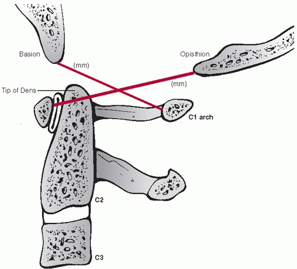
FIGURE 42-1
The Power ratio is calculated by dividing the distance between the basion and the posterior C1 arch by the distance between the opisthion and the anterior C1 arch. A ratio greater than 1 is suggestive of an atlanto-occipital dislocation. |
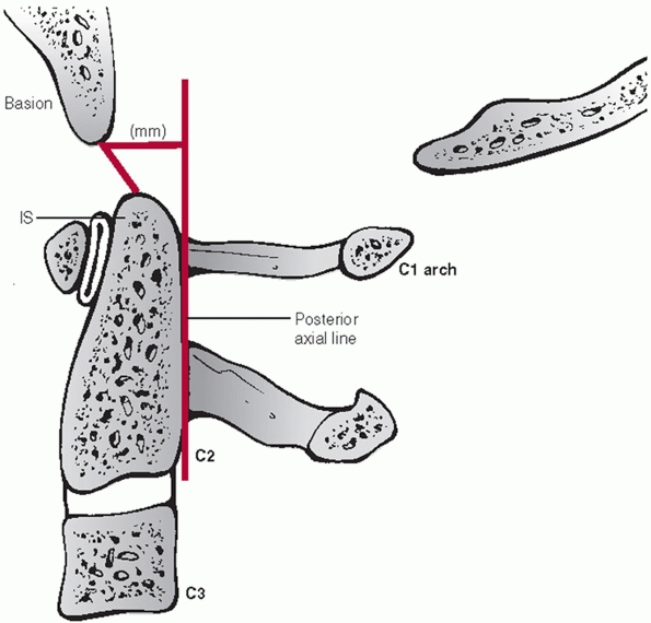
missed injuries, review of initial radiographic images must be
systematically performed. Evaluation begins at the occipitocervical
junction. In a recent consensus statement from the Spine Trauma Study
Group, Bono et al.35 reviewed
commonly used radiographic methods of assessing for occipitocervcial
dissociation. While the authors recognized the utility of the Power
ratio (Fig. 42-1), they recommended the
basion-axis interval (BAI) and basion-dens interval (BDI), also known
as Harris’ rule of twelve, as the method of choice (Fig. 42-2) because of its documented clinical utility. In its original development, plain radiographs were used.160 Recently, the BAI and BDI were reevaluated using sagittal CT images.160
Because CT eliminates magnification, the study authors suggested that a
threshold of 8.5 mm should be used for the BDI, while the BAI could not
be reliably measured.203
are the atlanto-dens interval (ADI) and the posterior atlanto-dens
interval (PADI) (Fig. 42-3). The former should
be less than 2 to 3 mL in adults. Widening of the ADI suggests injury
to the alar and/or transverse ligaments. The latter (PADI) represents
the AP diameter of the spinal canal at the level of C1. A PADI of less
than 13 mL is thought to be critical canal compromise. The cortical
border of the odontoid process should be inspected on plain film or
sagittal CT images to detect any subtle discontinuity. Of note, a
transverse residual scar is sometimes present within the odontoid waist
that should not be mistaken for a fracture. The occipital condyles
should be well located within the superior articular processes of C1.
Gapping or asymmetry can suggest dislocation. Although occipital
condyle fractures can sometimes be seen on plain radiographs, sagittal
and coronal
CT images are most useful for detecting these injuries. Fractures through the C2 pars are readily seen on plain radiographs.
 |
|
FIGURE 42-2
Harris measurements, also known as the “rule of twelve,” include the BAI (basion-axis interval) and the BDI (basion-dens interval). The BAI is the measured distance between the basion and a perpendicular line drawn in relation to the posterior vertebral body tangent line of C2. The BDI is the measured distance between the basion and the tip of dens. Both distances should normally be less than 12 mL. |
 |
|
FIGURE 42-3
The atlanto-dens interval is measured from the posterior surface of the anterior C1 ring to the anterior surface of the odontoid process (dens). The posterior atlanto-dens interval is measured from the posterior surface of the odontoid process to the anterior portion of the posterior C1 ring. |
does not allow visualization of the entire cervicothoracic junction
should be considered inadequate.238
Pulling traction on the patient’s arms can facilitate imaging this
region. However, this may be not feasible with concomitant injuries
such a shoulder dislocation or scapulothoracic dissocation. A swimmer’s
view entails placing one arm in a fully abducted position, while
leaving the other arm at the patient’s side. This somewhat diminishes
the obstructing shadows of the deltoid and shoulder joint to allow
clearer imaging of the lower cervical and upper thoracic vertebrae. On
a practical basis, the increasing availability of CT has obviated the
need for these additional plain radiographic maneuvers.
should be noted. Prevertebral swelling can be detected by assessing the
soft-tissue shadow thickness anterior to the vertebral bodies (Fig. 42-4).
If this measures more than seven mL in front of the C2-C3 disc space or
more than 21 mL at the C6-C7 disc space, there is a high likelihood of
a cervical spinal injury.167,223
Importantly, the absence of prevertebral (retropharyngeal) soft-tissue
swelling does not reliably rule out an occult cervical spine injury, as
its reported sensitivity is only 65%.129
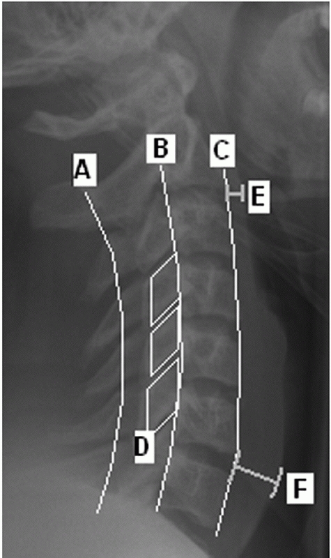 |
|
FIGURE 42-4 Radiographic lines, landmarks, and measurements using a lateral cervical spine film. The spinolaminar line (A), posterior vertebral body line (B), and anterior vertebral body line (C) are normally unbroken. On a perfect lateral view, the facet joints should appear as stacked parallelograms (D). The prevertebral soft-tissue shadow is measured at the C2-C3 (E) and C6-C7 (F) disc spaces. More than 7 mm at the C2-C3 and 21 mm at the C6-C7 disc is strongly suggestive of an underlying spinal injury.
|
negative static plain films and no other distracting injuries, lateral
flexion-extension views of the cervical spine can be obtained. They can
demonstrate instability in up to 8% of patients with negative plain
films;155 however, false-negatives can occur.123
In a patient with neck pain, they are best delayed until spasm has
subsided, which usually takes about 2 weeks. Spasm can mask subtle
instability, yielding a false negative study if performed too early
after injury.128,155
Flexion-extension views may be of limited utility in detecting
instability at the cervicothoracic junction in patients with
high-riding shoulders. Additional advanced imaging techniques may be
warranted. In the authors’ practice, flexion-extension views are
obtained by having the patient actively flexion and extend the neck
while in the seated or standing position. Thirty degrees of excursion
is the minimum acceptable amount to be considered an adequate method of
ruling out ligametous injury.
anatomic relationships and landmarks of the cervical spine. On a
good-quality AP view with the patient looking forward, the spinous
processes should be aligned. Displacement of a spinous process to one
side can suggest a rotational injury such as a unilateral facet
dislocation, facet fracture, or displaced pedicle fracture.13
The distance between each spinous process should also be gauged on the
AP view, as widening can suggest posterior ligamentous injury.
The spinolaminar line is perhaps the most useful, as it is not usually
affected by spondylotic changes such as osteophytes, which may be
present along the posterior vertebral body, and to a greater extent,
the anterior vertebral body. In older patients with substantial
degenerative changes, the morphology of the anterior vertebral body can
be quite abnormal making this landmark/line difficult to assess. The
lateral view is useful in judging the interspinous process distances.
These can be measured at each level and compared. Substantial widening
at one level suggests disruption of the posterior ligamentous complex
(PLC). The facet joints normally appear as stacked parallelograms on
the lateral cervical radiograph. In a perfect lateral view, the joints
on either side should overlie each other, facilitating assessment of
joint apposition.
description of detected injuries. With upper cervical spine injuries,
it is useful to describe some injury parameters. The stability of C1
Jefferson fractures is determined by the integrity of the transverse
ligament, which is inferred by the amount of lateral displacement of
the fracture fragments. Classically, this can be measured on an
open-mouth anteroposterior (AP) radiograph. The combined overhang of
the C1 lateral masses relative to the C2 lateral masses is measured, as
more than seven mL is thought to imply disruption of the transverse
ligament.89,216 As this
threshold was determined by direct anatomical measurements, Heller et al.127 concluded that, considering plain radiographic magnification, a threshold of 8.1 mL is more appropriate.
influenced by some of injury parameters. Odontoid fracture displacement
and angulation is commonly thought to affect the rate of nonunion.
Despite this commonness, consensus regarding a uniform measurement
method has only recently been suggested.35
In this work, displacement is measured along the anterior cortical
border of the odontoid after drawing lines tangent to each fragment (Fig. 42-5).
Similarly, angulation is measured at the intersection between the
tangent lines drawn along the posterior cortical border of the
fragments.
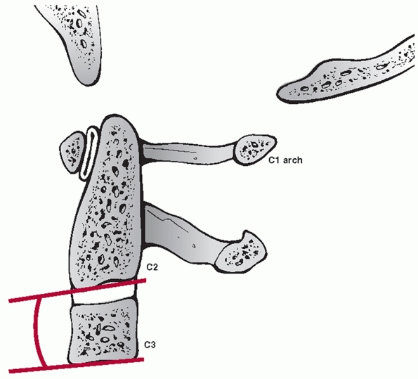
types, angulation following hangman’s fractures is not measured at the
fracture site. Instead, angulation between the C2 and C3 vertebral
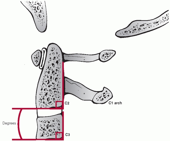
bodies is assessed. Two method have been described.35 In the endplate method, the angle between lines drawn along the inferior endplates of C2 and C3 is measured (Fig. 42-6).
In the posterior tangent method, the angle of intersection between
lines drawn along the posterior vertebral bodies of C2 and C3 is
measured (Fig. 42-7). Translation of C2 on C3 can be measured using posterior vertebral body tangent lines as described below for subaxial levels.
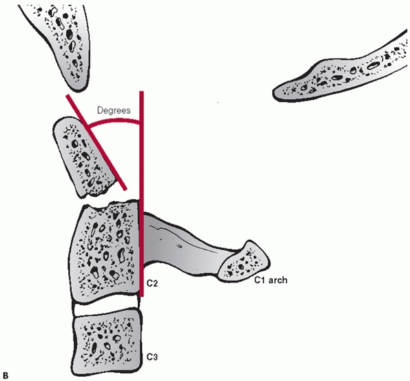
characteristics can be assessed and measured on a lateral cervical
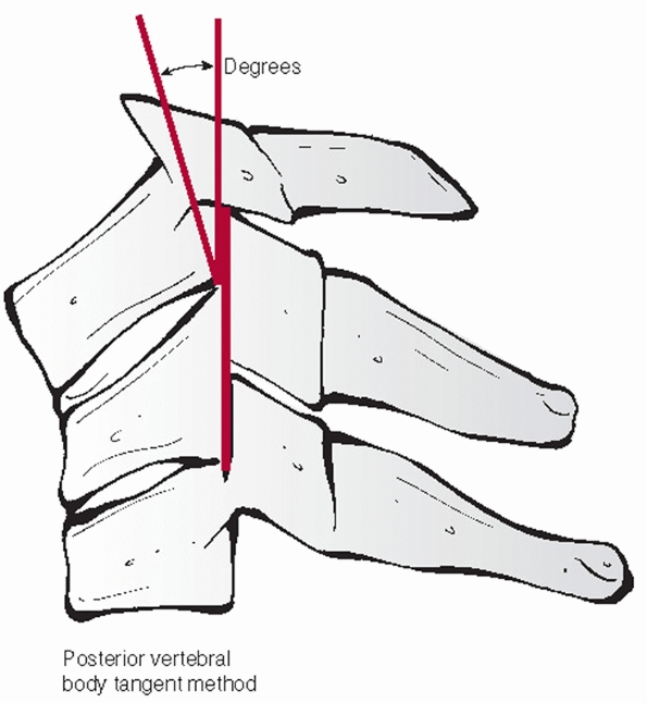
film. Segmental kyphosis can be measured by an endplate (Cobb) method
or posterior vertebral body tangent method (Figs. 42-8 and 42-9).
The latter may have lower interobserver variability. Kyphosis more than
11 degrees as measured by the endplate method is strongly suggestive of
posterior ligamentous injury and potential instability.248
Kyphosis can be the result of posterior widening of the interspinous
processes and facet joints about an injury axis of rotation near the
ALL. Vertebral body fracture with height loss and interspinous gapping
suggests an injury axis of rotation about the facet joints.
 |
|
FIGURE 42-5 A. Recommended measurement technique of odontoid displacement. (continues)
|
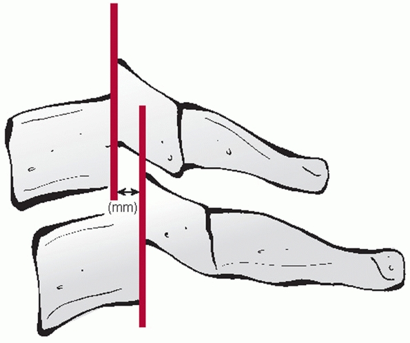
and measured on the lateral view. The distance between the posterior
vertebral body tangent lines at the level of the disc space can be used
to measure the absolute distance in milliliters (Fig. 42-10). According to the work of White and Panjabi,248
3.5 mL of translational deformity is suggestive of mechanical
instability. Lateral translation, although much less common, can be
measured on the AP view by drawing longitudinal (vertical) lines along
the lateral masses.
that can be performed on the lateral view. While it might reflect the
axial stability of the anterior column, there are no specific criteria
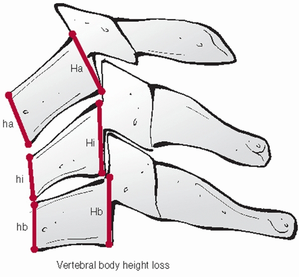
on a critical percentage of vertebral body height loss. The anterior
and posterior vertebral body heights should be measured at the injured
and adjacent uninjured levels. The distances of the uninjured levels
should be averaged and the percentage height loss for the anterior and
posterior vertebral bodies calculated (Fig. 42-11).
The relative amount of comminution should be noted, although this has
been more clearly categorized in the thoracolumbar spine. Primary
fracture lines, as are present with so-called tear-drop fractures,
should be outlined.
which can be obtained exponentially quicker than non-helical CT, have
facilitated acquisition of these highly-detailed studies. Cervical CT
has replaced the standard three-view plain radiograph trauma series as
the initial imaging modality of choice in many centers.65
High-quality sagittal and coronal image reconstructions have made this
transition easier, as alignment is more easily assessed in the
reformatted images. Motion artifact can often feign translational
deformity; evaluation by another imaging modality should be performed
before drawing treatment-influencing conclusions.
 |
|
FIGURE 42-5 (continued) B. Recommended measurement technique of odontoid angulation.
|
 |
|
FIGURE 42-6 Endplate method of measuring C2-C3 angulation.
|
 |
|
FIGURE 42-7 Posterior vertebral body tangent line method for C2-C3 angulation measurement.
|
 |
|
FIGURE 42-8
The Cobb method of measuring cervical kyphosis. A line is drawn along the superior endplate of the superior adjacent uninjured vertebrae; a second line is drawn along the inferior endplate of the inferior adjacent uninjured vertebrae. The angle subtended between the two is then measured. |
case. First, the vertebral bodies and pedicle should be labeled
according to level so that fractures or dislocations can be accurately
located. The vertebral body should be inspected for fracture lines. CT
is particularly useful for detecting sagittal fracture lines that are
usually less obvious on plain films. Fracture fragment
retropulsion
is readily appreciated on axial CT slices, as well as the degree of
comminution of vertebral body fragments. Pedicle fractures are often
undetectable with plain films, but easily detected on axial CT images.
Facet and lamina fractures are also easily detected on CT images.
 |
|
FIGURE 42-9
The posterior vertebral body tangent method of measuring cervical kyphosis. A line is drawn along the posterior aspect of the adjacent vertebral vertebral bodies. The angle subtended between the two is then measured. |
can occur with substantial amounts of translation, as can occur with
bilateral facet dislocations. Less obvious signs can be detected by
carefully examining the facet joints themselves. Unapposed articular
surfaces may result in a so-called empty facet sign. Knowledge of
normal anatomic relationships is crucial to detecting facet
dislocations. Importantly, the inferior articular processes of the
level above are normally posterior to the superior articular processes
of the level below. With completely dislocated, locked facet joints,
this relationship is reversed. Lamina and spinous process fractures are
readily appreciated on axial images.
 |
|
FIGURE 42-10 Sagittal translation is measured at the level of the inferior aspect of the superior vertebral body.
|
 |
|
FIGURE 42-11
Vertebral body height loss can be expressed as a percentage. This is best assessed by measuring both anterior and posterior height of the injured and adjacent uninjured vertebral bodies. |
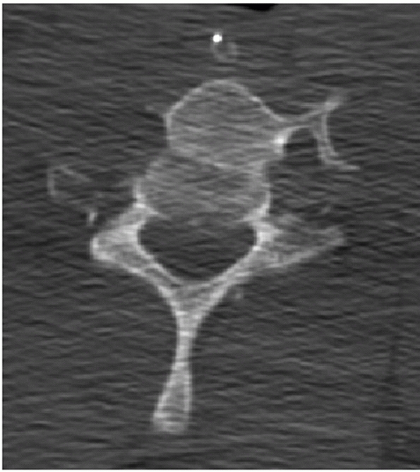
understanding the three-dimensional nature of spinal injuries.
Paramedian slices through the facet joints can help visualize
dislocations, subluxations, or fracture fragment size (Fig. 42-13).
Canal occlusion is best appreciated on mid-sagittal CT reconstructions.
Widening of the occipitoatlantal joints and occipital condyle fractures
are best appreciated on coronal and sagittal images.
The
stability and healing potential of occipital condyle fractures is
influenced by fracture site gap and the size of the fracture fragment.
Fracture gap can be measured on both coronal and sagittal CT
reconstructions, although, to date, there has been no critical
threshold reported for this parameter. The size of the fragment can be
expressed as a ratio of the fractured articular surface to the
unfractured, apposed articular surface.
 |
|
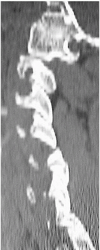
FIGURE 42-12
Frank dislocation is usually obvious on axial CT images, as in this case of a C6-C7 fracture dislocation. More subtle amounts of translation, however, can be easily missed using axial CT images alone. |
 |
|
FIGURE 42-13
Paramedian CT reconstructions are useful for assessing the facet joints. In this case, a C4-C5 unilateral facet perch can be appreciated. |
Its superiority in visualizing the spinal cord, intervertebral disc,
and spinal ligaments gives it some advantages over CT. MRI can detect
subtle bone edema that is associated with vertebral body fractures.
However, image clarity of bony architecture is inferior to CT, making
it unsuitable as a stand-alone modality for fracture description. The
most useful applications of MRI are in detecting traumatic disc
herniations, epidural hematomata, spinal cord edema or compression, and
posterior ligamentous disruption.105,141
following situations: (1) patients with neurological deficits, barring
a contraindication to MRI, and (2) patients with injuries in which the
integrity of the posterior ligamentous complex is unclear and would
directly influence the treatment plan. Of concern is that MRI tends to
be overly sensitize in detecting fluid or increased signal within the
posterior tissues, which can lead to a false-positive reading for
posterior ligamentous injury.
in which the cerebrospinal fluid (CSF) is bright and tissues such as
disc herniations are relatively dark or isointense. T2-weighted images
can also demonstrate increased signals within the disc, facet capsules,
or posterior interspinous process region that may be a sign of edema
and disruption. The anatomical outlines of the ALL, PLL (and tectorial
membrane, as it is renamed at the occipitocervical junction), and
ligamentum flavum can also be detailed on T2-weighted MRI (Fig. 42-14).
Of note, discontinuity of the ALL may not necessarily imply disruption,
as this is a frequent finding on nontraumatized cervical spines.208
STIR (short inversion time inversion-recovery) images are more
sensitive than T2-weighted images in detected soft-tissue or bony
edema. (They are like an exaggerated T2.) This is, however, at the
sacrifice of image detail. On high-quality axial images through C1, the
integrity of the transverse and alar ligaments can often be delineated (Fig. 42-15).
 |
|
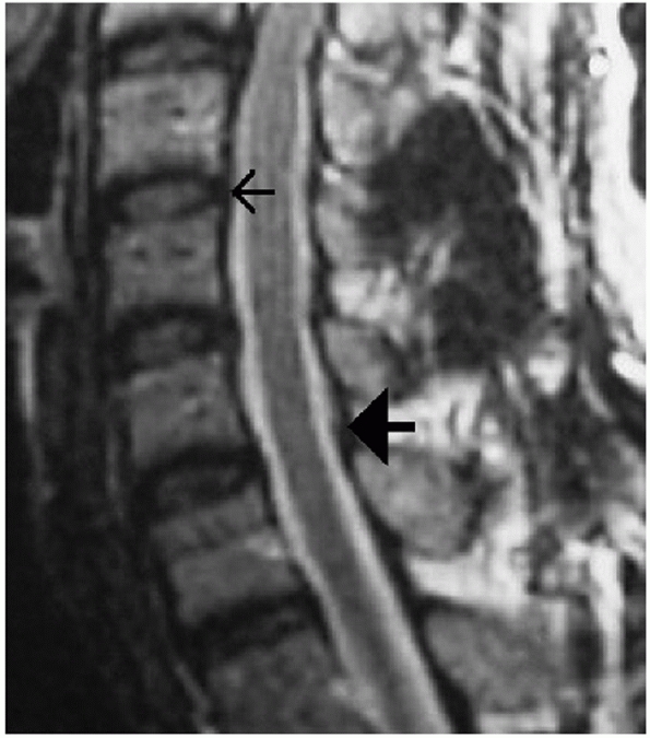
FIGURE 42-14
MRI can be used to assess several important soft-tissue structures. In this sagittal T2-weighted image of an uninjured cervical spine, the small arrow is pointing to the PLL. The large solid arrow is pointing to the ligamentum flavum. |
 |
|
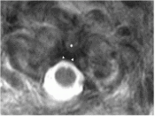
FIGURE 42-15 Axial T2-weighted MRI through the C1 ring, showing an intact transverse process (arrows) spanning from the C1 lateral masses over the posterior surface of the odontoid process (asterisk).
|
visualize vascular structures. MR arteriograms can be used to assess
the patency of the vertebral arteries. This may be indicated in cases
of suspected arterial injury, such as severe dislocations or fractures
that extend into the transverse foramen. The precise indications for
evaluation of the vertebral arteries following cervical trauma are not
clear. Some centers pursue imaging in nearly all cases, while others
are more conservative. Ultimately, the decision to obtain an MR
arteriogram of the vertebral arteries is greatly influenced by the
practitioner’s belief that an occluded vessel should be treated with
anticoagulant therapy. As unilateral occlusions are usually clinically
asymptomatic and recanalization can occur over time, the necessity of
urgent anticoagulant therapy cannot be considered absolute.
(C2), and the base of the skull (C0), which includes the occiput. The
anatomy of each level is unique from each other and the rest of the
spine. The lower cervical spine, also known as the subaxial cervical
spine, includes the C3 to C7 vertebral segments. In contrast upper
cervical segments, the subaxial cervical vertebrae have a relatively
uniform anatomical configuration that is analogous to the thoracic and
lumbar regions.
of the cranium that cradles the cerebellum and brainstem. At its
anterior and inferior aspect, it forms the posterior part of the
foramen magnum, which transmits the spinal cord into the spinal canal.
The occiput has several bony structures that are useful surgical
landmarks. At its topographical center, the external occipital
protuberance (EOP) is a dense uprising that marks the thickest portion
of the bone (Fig. 42-16). The superior nuchal
line is a ridge that extends medial and lateral from the EOP. The
inferior nuchal line is a similar condensation running parallel and
below its superior counterpart. Although not a useful surgical
landmark, the lamboidal suture denotes the borders of the occipital
bone at its fused junctions with the temporal and maxillary bones. The
occiput curves sharply anterior from the superior nuchal line to the
foramen magnum. This feature makes accurate contouring of implant to
match the skeletal geometry challenging. The occiput interacts with the
cervical spine through bilateral articular condyles on either side of
the foramen magnum. Together with the posterior and anterior ligaments,
the occipitoatlantal joints stabilize the head on the neck. Motion at
this junction is minimal, allowing 13 degrees of capital
flexion/extension, 8 degrees of lateral bending, and no rotation.1
 |
|
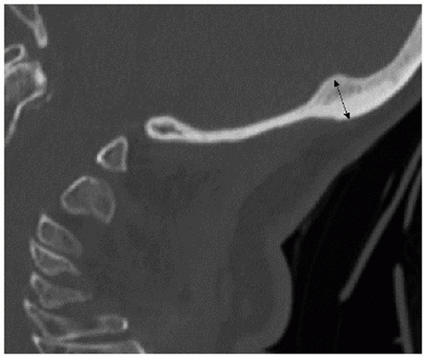
FIGURE 42-16
Sagittal CT reconstruction through the occiput demonstrating that the EOP (external occipital protuberance) lies at the thickest portion of the bone. |
ligaments. A durable capsule stabilizes the the articulation of the
occipital condyles to the atlas. A broad sheet of fibrous tissue
extends from the posterior border of the foramen magnum to the superior
surface of the C1 ring. This is the tectorial membrane, which is
analogous to the posterior longitudinal ligament (PLL) in the lower
cervical spine. A loose and flexible sheet of fibrous tissue spans
between the lower occiput and the posterior C1 ring. This is called the
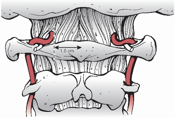
posterior atlantooccipital membrane and is analagous to the ligamentum
flavum at other levels. Entering this membrane approximately 1.5 cm
from the midline is the vertebral artery (Fig. 42-17).
The artery arises lateral and posterior from the transverse foramen of
the atlas. This vessel can be injured with extensive exposure of the
posterior ring. The ligamentum nuchae is a thick condensation of
supraspinous fibrous bands. This structure overlays the spinous
processes of the cervical vertebrae and extends from the EOP to C7.
occiput and the atlas. The superior obliquus capitis muscle spans from
the lateral aspect of the superior nuchal line to the transverse
process of C1. Medially, the rectus capitis posterior minor attaches to
the superior nuchal line and the C1 spinous process. The rectus capitis
posterior major muscle extends from the superior nuchal line to the
spinous process of C2. Spanning from the mastoid process of the skull,
the longissimus capitis blends with the deep muscles of the upper
thoracic paraspinal region.
The atlas has large broad-based articular processes to interface with
the occipital condyles superiorly and the axis inferiorly. An articular
surface on the posterior aspect of the anterior arch faces the odontoid
process of the axis. The posterior ring of C1 is quite thin with no
discrete spinous process. The axis articulates with C1 at three points:
broad bilateral superior articular surfaces and the odontoid process.
By its morphology, it allows approximately 47 degrees of rotation (50%
of axial rotation of the entire cervical spine), while limiting
flexion/extension to 10 degrees. Virtually no lateral bending is
permitted at the atlantoaxial articulation. The axis marks the
transition between the upper and lower cervical spine. In so doing, the
inferior articular processes of C2 are offset posteriorly. Because of
this offset, the pars interarticularis sustains high shear forces with
axial loading, predisposing it to the classic hangman’s fracture
pattern. Again, a foramen in the transverse processes transmits the
ascending vertebral artery. The cervical nerves roots exit through
foramina formed by adjacent superior and inferior pedicle walls. The
ligamentum flavum proper is first discovered at this level, extending
from the inferior ring
of
C1 to the suiperior ring of C2. The flavum attaches more anterior
(deep) on the C1 ring and more posterior on the C2 ring. This is an
important consideration when elevating this membrane to expose the bony
lamina for decompression.
 |
|
FIGURE 42-17
During exposure of the posterior C1 arch, dissection should not extend beyond 1.5 mm as to avoid injury to the vertebral artery. |
spinal regions, small bilateral interspinalis muscles span between
spinous processes. The inferior obliquus capitis extends from the
transverse process of C1 laterally to the spinous process of C2
medially. It is at the inferior border of this muscle that the greater
occipital nerve exits posteriorly, travelling cranial and medial to lie
superficial to the rectus capitis posterior minor and obliquus capitis
superior muscles. Finally, it exits the trapezius near the midline over
the EOP and can be injured with lateral dissection at this level. Nerve
injury can lead to anaesthesia of the posterior scalp, which can be
troublesome to some patients.
 |
|
FIGURE 42-18
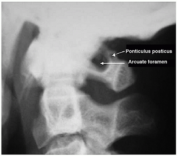
Lateral radiograph of a patient with a ponticulus posticus, an anomalous bony encapsulation of the vertebral artery along the superior portion of the C1 ring. (From Young JP, Young PH, Ackermann MJ, et al. The ponticulus posticus: implications for screw insertion into the first cervical lateral mass. J Bone Joint Surg Am 2005;87A:2495-2498.) |
fact, oblong, as its coronal diameter (left to right) is larger than
its sagittal diameter (anterior to posterior). In distinction from the
normally flat endplates of the thoracic and lumbar vertebrae, cervical
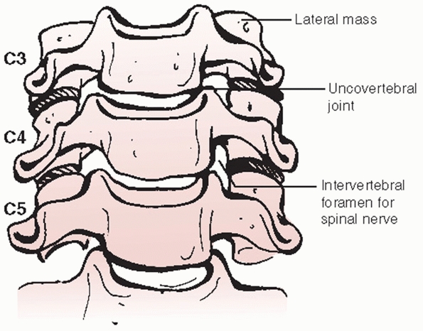
endplates have a cup-in-saucer configuration. Viewed from the front (Fig. 42-19),
bilateral uprisings called uncinate processes are present along the
lateral aspects of the superior endplates. The uncinate processes
articulate with rounded inferolateral borders of the suprajacent
vertebral body. This articulation, called the uncovertebral joint, is a
useful surgical anatomical landmark that signals proximity to the
lateral extent of the vertebral body. Mechanically, it is believed to
limit posterior translation of the upper vertebra.248
endplates of adjacent vertebral bodies. The annulus fibrosis is
intimately related to the anterior and posterior longitudinal
ligaments. The longus colli muscles lie directly over and insert onto
the anterolateral
aspects
of each cervical vertebrae. The sympathetic plexus lies on top of the
lateral muscle belly, placing it at risk with overly aggressive
dissection or retraction, which may lead to a Horner’s syndrome. The
prevertebral (deep) and alar (superficial) fascial layers separate the
spine from the overlying esophagus.
 |
|
FIGURE 42-19
Diagram of the subaxial cervical spine viewed from the front. The bilateral uprisings, known as the uncinate processes, create a cup-in-saucer formation of the intervertebral disc space. |
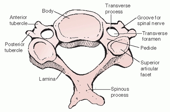
the vertebral body. In contrast to their flat, solid analogues in the
thoracic and lumbar spine, cervical transverse processes have a more
complex anatomic shape. This is the result of distinct developmental
formation. The anterior portion (Fig. 42-20) of
the transverse process is actually the remnant of a rudimentary costal
process. While these form ribs in the thoracic spine, in the cervical
spine it partially fuses with the posterior portion (the true
transverse process analogue) to form a vertebral artery foramen. The
vertebral artery, a longitudinal coalescence of cervical segmental
vessels, ascends to the head through the C6 to C1 transverse foramina.
It enters the C7 transverse foramen in only 5% of the population.140
Fractures that enter or displace the transverse processes suggest
possible traumatic injury or occlusion of the vertebral artery.
vertebral artery, the transverse process guides the cervical spinal
nerves as they egress from the spinal canal. The spinal nerves lie
posterior to the vertebral artery. Viewing the spine from the side, the
spinal nerve appears to be cradled by the half-pipe configuration of
the transverse process (Fig. 42-21) that projects slightly inferior and anterior.
posterolateral to anteromedial orientation. They form the posteromedial
border of the vertebral artery foramina. The internal morphology of
cervical pedicles, including the medial and lateral cortical thickness,
can vary substantially between vertebral levels and between men and
women.77,188 These characteristics make transpedicular screw insertion extremely technically demanding.
articulations, are highly mobile diarthrodial joints formed by the
interaction of superior and inferior articular processes. They emanate
from the posterior aspect of the pedicles and transverse processes (Fig. 42-21).
The articular surfaces are angled approximately 45 degrees in relation
to the transverse axis of each segment. There is minimal, if any
coronal angulation. The pillar of bone between the superior and
inferior articular processes is commonly referred to as the lateral
mass. It is a useful site for posterior screw or wire stabilization of
the cervical spine.
 |
|
FIGURE 42-20
The transverse process is made of two components. The anterior portion is actually the remnant of a costal process (i.e., rudimentary rib). The posterior portion is the true developmental transverse process. Together, they form the transverse foramen, the conduit for the vertebral artery. |
 |
|
FIGURE 42-21 The tranverse process forms a half-pipe configuration that cradles the exiting spinal nerve.
|
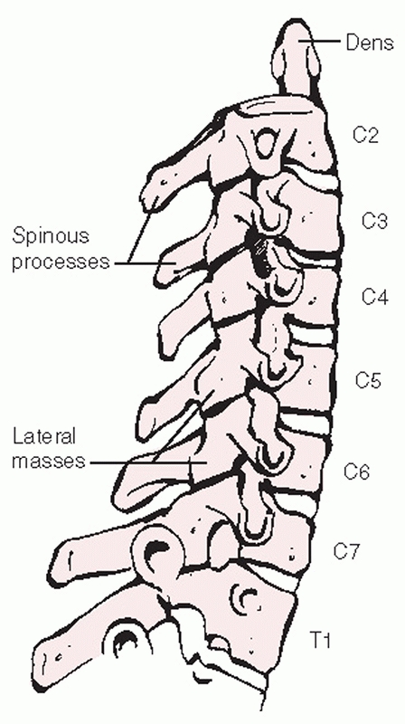
lateral masses. The laminae project posterior and toward the midline to
form bifid spinous processes (C2-C6). An elastic yellow ligament,
called the ligamentum flavum, spans the interlaminar spaces. Strong
interspinous and supraspinous ligaments (ligamentum nuchae), together
form a posterior ligamentous complex (PLC). Disruption of this complex
results in mechanical instability.
-
Anterior: vertebral body, intervertebral disc, posterior longitudinal ligament
-
Posterior: laminae, ligamentum flavum
-
Lateral: pedicles, medial aspect of the facet joints
injury several ways. Bony fragments, most often retropulsed vertebral
body fragments, can intrude upon the canal and spinal cord. Perhaps the
most common reason for canal compromise after cervical trauma is
translational malalignment, as occurs with facet joint dislocations (Fig. 42-22).
In these cases, the bony canal/neural arch itself can be intact;
however, their relative position causes overall canal compromise. This
kind of canal compromise can be underestimated by axial CT images. Disc
herniations and epidural hematoma can also cause canal compromise and spinal cord compression.
 |
|
FIGURE 42-22
Spinal canal compromise in the cervical spine most commonly occurs from translational deformity, as depicted in the sagittal CT reconstruction of a patient with bilateral facet dislocations. This injury was associated with a complete spinal cord injury. |
is the posterior surface of the odontoid process, while the posterior
border is the anterior surface of the posterior C1 ring. It is the only
transverse level in the spine for which the spinal canal border is
composed of elements from two different vertebrae. Accordingly, spinal
canal compromise can result from dislocation of the C1 ring relative to
the odontoid process.
ischemia, compression, distraction, penetration, or various
combinations thereof. Knowledge of spinal cord and nerve root anatomy
is useful in determining the level and type of spinal cord injury.
made up of white matter covered by dura mater. The white appearance is
from myelin that sheaths the axons being transmitted between the brain
and peripheral tissues. There are several afferent and efferent tracts
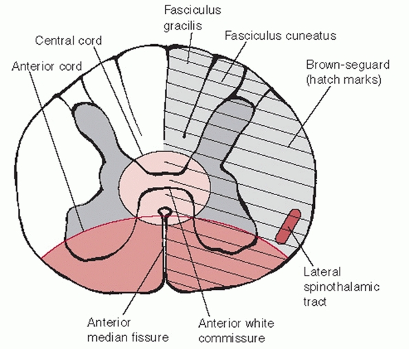
that are embedded within the substance of the white matter (Fig. 42-23).
The lateral spinothalamic tract is an afferent (ascending) tract
located within the anterolateral aspect of the cord that transmits pain
and temperature sensation. It is somatopically arranged; representation
of more cephalad levels is within its anteromedial aspect and that for
more caudal levels within its posterolateral aspect. Pain and
temperature nerve fibers decussate at the level they exit the spinal
cord. Therefore, injury to the lateral spinal thalamic tract results in
pain and temperature loss of the contralateral side of the body.
They transmit nonnoxious (not pain and temperature) sensory input to
the brain. This includes proprioception, vibratory sense, pressure, and
tactile discrimination (touch). The dorsal columns are also arranged
somatopically. However, more cephalad innervation is located within the
lateral regions of the tract. Tract fibers decussate above the foramen
magnum before the spinal cord is formed. Injury therefore causes
ipsilateral deficits.
 |
|
FIGURE 42-23
Cross section through the spinal cord. There are distinct somatotopic patterns of innervation, which help explain the clinical presentation of various types of incomplete spinal cord injury. |
cross section of the spinal cord, it has as a butterfly or H-shaped
appearance and as such has been divided into dorsal and anterior horns
(see Figure 42-23). The dorsal horns contain
sensory nerve cell bodies that transmit pain, temperature, and touch.
The anterior horns contain motor nerve cell bodies. Grey matter is
topographically arranged so that more cephalad innervation is located
within its central aspects. This helps explain why patients with
central cord syndrome have upper extremity greater than lower extremity
involvement.
important goals. Preservation or restoration of neurological function
is the most important. It entails decompression of the neural elements,
which can be effected by realignment or direct removal of bone or disc
material from the spinal canal. Mechanical spinal instability may be
the result of the initial injury or decompressive surgery. Protection
of the neural elements also requires that mechanical stability be
restored to unstable segments. This is usually achieved by open
surgical methods, although closed methods such as halo-fixation can
sometimes be effective.
make the academic distinction between neurological stability and
mechanical stability. In theory, as long as a patient with a
mechanically unstable cervical injury remains flat and strict spinal
precautions maintained, neurological stability can be maintained. In
other words, the stresses that the spine would endure under these
specific circumstances would pose little additional endangerment to the
spinal cord. With more aggressive
movement, neurological stability would depend on restoration of mechanical stability.
nonoperatively. The most common method of nonoperative treatment is
immobilization in a cervical orthosis. In reality, orthoses decrease
motion rather than effect true immobilization. Orthoses work through
padded contact areas strategically located over subcutaneous bony
prominences. Specifically, these are the occiput, spinous processes,
scapular spines, acromion processes, clavicles, sternum, and mandible.
Interestingly, motion at the occipital-cervical junction is slightly
increased by most cervical collars.138
They are most commonly used after cervical strains or sprains,
otherwise known whiplash-type injuries. Soft collars are worn for
comfort.
immobilization depending on the construct material and the overall
design. They are commonly used for emergent in-field cervical spine
immobilization. An important design feature of all cervical orthoses is
inclusion of a window or cut-out over the anterior neck to allow access
to a tracheostomy, if present. The most effective means of in-field
cervical spine immobilization is strapping the chin and forehead to a
rigid spine board.56 With this, addition of a cervical collar offers little additional stability.
collars. A radiographic study demonstrated that the NecLoc restricted
more sagittal (flexion-extension), axial rotation, and lateral bending
motion than the Miami J, Philadelphia, Aspen, or Stiffneck devices.16 The Miami J restricted extension better than the Philadelphia and Apsen collars.16
Despite these detected radiographic differences, the clinical
superiority of one device over another has yet to be demonstrated.
cervical collars. Skin breakdown at bony prominences, in particular the
occiput, mandible, and sternum can occur. Up to 38% of patients with
severe closed head injuries can develop skin complications with
prolonged use.54 This places a
priority on early injury exclusion (“clearing”) of the cervical spine
so that unnecessarily protracted collar wear can be avoided.
extend to the upper thorax. In this way, the braces provide more
effective immobilization than simple cervical collars in all planes.138,139
Types include the sterno-occipito-mandibular immobilizer (SOMI),
Minerva brace, and the Yale device. Mechanical studies have
demonstrated that between 79% to 87% of sagittal motion, 75% to 77% of
axial rotation, and 51% to 61% of lateral bending motion is restricted
in these orthoses.137,213,256
The disadvantages of CTO braces are that they are more difficult to
apply/remove and produce high resting pressures on the chin and occiput.94
Like simple cervical collars, CTOs have demonstrated increased motion
at the occipitocervical junction. CTOs alone are not an effective means
of immobilizing the spine below the C7-T1 junction.
different goals. Traction can be used to help provide temporary
immobilization of unstable cervical spine injuries.180
This may be of particular benefit when transferring patients to and
from institutions or for patients awaiting operative stabilization.
cervical spine fractures or dislocations. This is achieved by
application of gradually increasing amounts of weight in conjunction
with frequent radiographic examination. Traction should not be used in
cases in which occipitocervical instability or dissociation is present
or suspected. Furthermore, traction should not be used to realign a
subaxial spine injury if there is a concomitant type IIA traumatic
spondylolisthesis. As such concomitant injuries may not always be
initially recognized, light traction (5 to 10 pounds) should be applied
first, followed by a lateral radiograph to look specifically for signs
of abnormal distraction between the cervical spinal segments or
occipitocervical junction.214
the cervical spine are Gardner-Wells (G-W) tongs and the halo-ring. In
general, G-W tongs can be applied more quickly and easily than a
halo-ring. However, G-W tongs are temporary devices that are usually
removed after surgical stabilization. Traction is applied using a
halo-ring if the planned definitive treatment includes halo
immobilization.
subaxial spinal injuries. Realignment of an injury can provide some, if
not complete, spinal canal decompression. An example of this is
reduction of bilateral facet dislocations. Fracture fragment
retropulsion, such as that produced with burst-type injuries, is
usually associated with vertebral body height loss and comminution.
With application of cervical traction, ligamentotaxis can partially
reduce these fragments and produce some degree of canal decompression.
This maneuver, however, relies on sufficient continuity of the
posterior longitudinal ligament. Segmental, traumatic kyphotic
angulation can also be improved with application of traction.
The biomechanical strength of the traction device is of particular
significance if such practices are employed. Steel tongs are stronger
than titanium-alloy or carbon-fiber tongs, although the latter two are
MRI-compatible.31 Because pull-out
strength is diminished with repeat usage, it has been suggested that
steel cranial tongs should be recalibrated after frequent usage.152 According to their manufacturers’ recommendations, carbon-fiber tongs should only be used once.
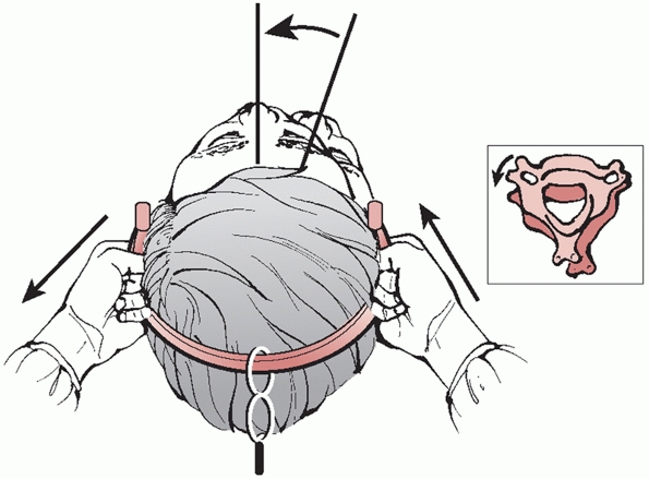
to the skull through two, slightly cranially-angulated, fixation pins.
Prior to application of cranial-based traction, plain radiographs or a
cranial CT should be carefully inspected to rule out skull fractures.
The optimal site of insertion is approximately 1 cm above the helix of
the ear. Neutral pin position is aligned with the external auditory
meatus, which best achieves longitudinal traction. By placing the pins
slightly anterior or posterior to this point, extension or flexion
moments can be delivered to help reduce kyphotic or hyperlordotic
deformities, respectively (Fig. 42-24). The skin over the proposed pin site should be marked and prepped sterile with povidone-iodine or Betadine solution.
It is not necessary to shave the site, as is routinely performed when
inserting halo pins. The area is then anesthetized with a local
infiltration of lidocaine, raising a skin wheal, as well as delivering
the medication to the underlying periosteum.
 |
|
FIGURE 42-24
Application of Gardner-Wells tongs can be useful in reducing fractures and dislocations. Neutral position is just proximal to the external auditory meatus, about 1 cm above the ear. By placing the pin slightly anterior, an extension moment can be applied. Similarly, by placing the pin slightly posterior, a flexion moment can be applied. |
advanced to and through the skin until they engage the outer cortex of
the cranium. Most tongs have an indicator on the pin ends that signal
when appropriate force has been applied. It is important not to
overtighten the pins, as they can penetrate the inner diploe of the
skull, which might lead to intracranial injury. In contrast, pins that
are insufficiently secured can loosen and pull-out from the skull,
leading to substantial bleeding from scalp laceration or, rarely,
temporary artery injury.183 Brain abscess has also been described as a complication of cranial tongs.166
G-W tongs can applied as described earlier. However, application of
halo ring may be more appropriate if halo vest immobilization is the
planned definitive treatment. With most acute fractures, longitudinal,
in-line traction with low weight (5 to 30 pounds) is usually effective
to correct angulation deformity. Translational deformity can be more
difficult to correct. One group used so-called bivector traction to
help reduce posteriorly displaced odontoid fractures in which a second
traction line is used to deliver an anterior force.206
Alternatively, bolsters or towel rolls can be placed behind the head to
help reduce posterior translation. Conversely, the thorax can be
elevated using bolsters or rolls to help reduce anteriorly translated
odontoid fractures. An initial weight of 5 to 10 pounds should be
applied, followed by a lateral radiograph to rule out occult
occipitocervical instability or gross overdistraction through the
fracture, both of which should prompt slow and careful release of
traction.
A towel roll can be placed between the patient’s scapulae to raise the
head slightly off the bed. Because the facet reduction requires some
flexion in addition to distraction, the pins should be placed slightly
(1 cm) posterior. The location of the so-called equator of the skull
should be noted. If pins are located above (cranial) the equator, they
can slide along the slope of the cranium and dislodge. By positioning
the pulley anterior to the patient, the traction vector can be used to
apply a flexion moment to the cervical spine. Rolled towels can also
aid in producing neck flexion, which can help unlock the articular
processes. It is important that the traction set-up will allow
subsequent adjustments, as it should be changed to a neutral or
slightly extended vector once the facets have been reduced. Likewise,
the rolled towels are removed after reduction to allow neck extension,
which will help hold the facet joints reduced.
pounds should be applied followed by a lateral radiograph to rule out
overdistraction through the injured or distant site, both of which
should prompt slow and careful release of traction. Serial neurological
examinations should be performed by the same practitioner throughout
the entire process. Weight can then be added in 10-pound increments
every 10 to 15 minutes, followed by a lateral cervical radiograph,
until reduction is achieved. While some have proposed that no more than
55 or 60 pounds should be used, weights as high as 140 pounds have been
safely used to obtain cervical reductions.61
If such maneuvers are used, it is paramount that the patient be awake,
alert, and examinable. After reduction is radiographically confirmed,
the weight is reduced to 10 to 15 pounds and the traction vector
adjusted to produce slight neck extension. If MRI is to be obtained
following reduction, the patient is placed in a rigid cervical collar
and the cranial tongs temporarily removed.
Unilateral facet dislocations are typically lower-energy injuries than
bilateral dislocations. Because of this, they are often quite stable in
the dislocated position and can require greater amounts
of
weight to reduce. While some authors have treated these injuries
nonoperatively, provided the patient is neurologically intact, most
recommend reduction and stabilization.23,24
dislocations, with a flexion moment to facilitate unlocking of the
dislocated joints. In some cases, a closed reduction maneuver can be
performed to achieve an earlier reduction with possibly lighter
weights. The practitioner should grasp of the cervical tongs like a
steering wheel, with his or her hand placed just above the pins sites
(in the 4 and 8 o’clock positions). Axial compression is applied to the
nondislocated side, while longitudinal distraction is applied to the
dislocated side. The dislocated facet should now be unlocked (Fig. 42-25).
Final reduction entails reversing the rotational deformity by rotating
the head toward to the dislocated side. A subtle click or thump can be
heard or felt. Manual traction should then be slowly released and a
lateral radiograph obtained to confirm the reduction. Once reduced,
traction should be decreased to 10 or 15 pounds and the neck slightly
extended. Neurological status must be serially assessed through the
process.
The role of prereduction MRI for facet dislocations remains
controversial. There exists the potential for neurological decline with
closed reduction, either by open or closed methods.79,161
It is believed that intervertebral disc herniations, pulled back into
the spinal cord during reduction, are a major contributing factor.
Because of this, some have strongly advocated a MRI prior to reduction
to rule out a disc herniation.79
This recommendation is poised, however, on a decision to perform an
anterior cervical discectomy or corpectomy to remove the herniated disc
prior to open or closed reduction.
 |
|
FIGURE 42-25
Reduction maneuver for a unilateral right-sided facet dislocation. With the tongs in place and weight applied, distractive force is applied to the dislocated side, while compressive force is applied to the nondislocated side. The head is then rotated toward the dislocated side. A satisfying “clunk” signifies that the dislocation has been reduced. |
intoxicated) patient with an unknown or unmonitorable neurological
status, a prereduction MRI appears to be prudent. However, in the
awake, alert, and examinable patient, a prereduction MRI may not be
necessary. Two recent clinical reports have demonstrated that closed
reduction of facet dislocation can be performed safely, provided that
serial neurological examination can be adequately performed.112,233 In one study,233
five of nine patients who underwent a successful closed reduction
without neurological compromise had a new herniated disc on
postreduction MRI that was not present on prereduction MRI. In
addition, some patients also had increased signal within the spinal
cord, but again, without associated neurological compromise. Grant et
al.112 retrospectively reviewed
their results with early closed reduction in 121 patients with cervical
spine dislocations. Of the 80 patients who underwent a postreduction
MRI, 22% demonstrated a frank disc herniation, although this did not
affect the degree or progression of neurological deficit. Ultimately,
the relative advantages and disadvantages of early reduction and
anatomical alignment versus the increased complexity of performing
anterior decompression and reduction on a dislocated spine are still
not clearly established and will likely remain controversial in the
near future.
with improved techniques of rigid internal fixation of the cervical
spine, halo immobilization has become a less popular form of treatment
for subaxial cervical spine injuries. As discussed earlier, halo-based
traction can be used, in particular when definitive treatment with a
halo vest is planned. Halo fixation may also be a useful method of
temporary stabilization of highly unstable cervical spine injuries in
multiply injured patients who must undergo diagnostic and nonspine
surgical procedures.125
The use of halo fixation for cervical facet dislocations has
demonstrated a high rate of persistent instability and poor anatomical
alignment.186,210,249 Varying rates of success have been documented for other types of subaxial cervical injuries.58,68,82,159
Despite this, halo vest immobilization remains a viable, minimally
invasive method of stabilization of unstable cervical spine injuries
for patients who might otherwise have contraindications to open
surgical methods. Halo fixators are the best nonoperative method of
resisting rotational and translational forces,170 while they are relatively ineffective at resisting axial compressive loads.
or realigned using the halo ring, the traction can remain in place
until final securing of the construct. The posterior part of the vest
can be placed first by logrolling the patient from side to side,
keeping in line cervical traction at all times. The anterior part of
the vest can be applied and secured using the shoulder straps and side
buckles. An appropriately fitted vest should extent down to the level
of the xiphoid process, keeping the abdomen free, and be secured enough
to maintain its position while still allowing access to the underlying
skin. Proper vest fit has been demonstrated to be the most important
factor in maintaining reduction.170
occiput. The proposed pin sites should then be prepped in sterile
fashion. The hair should be shaved from the posterior pin sites prior
to sterile preparation. The optimal position of the anterior pins is 1
cm above the lateral third of the orbital rim (to avoid injury to the
supraorbital nerve), while the posterior pins should be placed 1 cm
above the helix of the ear.37 The
pins or ring should not contact the ear, as even gentle pressure can
lead to skin necrosis over time. Opposing pins should be tightened at
the same time to avoid displacement of the ring (i.e., the anterior
right pin and the posterior left pin are tightened together). Optimal
pin fixation is achieved if placed perpendicular to the bone.
Tightening should be gradual, switching between the two pairs of
opposing pins until the final torque of 8 inch-pounds is achieved. The
lock nuts are then tightened to prevent pin loosening. Pins should be
retightened 24 to 48 hours later. If a pin becomes loose with time, it
can be retightened once to 8 inch-pounds if resistance is met. If not,
then another pin should be placed in a new site and the loosened one
removed. Even with meticulous pin site care, complications occur in
about 6% of cases.241 Once the ring
has been secured, the longitudinal struts are attached and secured.
Cervical radiographs can then be obtained and careful adjustments made
to the device to optimize reduction and alignment.
Patients can report swallowing difficulty, which may be associated with
the head and neck being overly extended. Returning the neck to a
neutral or slightly flexed position can relieve this in most cases.
Pressure sores can develop in 4% to 11% of patients99
and are usually associated with improper vest fit. Meticulous skin care
and frequent inspection can help avoid this complication.
fracture management has diminished with the development of rigid,
segmental fixation of the cervical spine. Historically, the halo vest
has been used to treat a wide variety of cervical fractures and
dislocations. In a retrospective review of 124 cases of cervical spine
injuries, Bucholz and Cheung44
reported successful management of 85% of patients with a halo vest,
although the investigators recognized its shortcoming in perched or
locked facets, difficult reductions, and older injuries (i.e., delayed
treatment).
treated 33 patients with varying cervical fractures in a halo vest.
Similar to Bucholz and Cheung’s series, success was achieved in 85% of
cases, with less favorable results in those with subluxations and
primarily ligamentous injuries. This group further warned of the perils
of using a halo in patients with spinal cord injuries who have
insensate skin as they are at high-risk for breakdown. In a more
contemporary work, Vieweg and Schultheiss243
analyzed the results of halo vest immobilization in 682 patients with
various upper cervical injuries. While it was effective for isolated
Jefferson fractures, hangman’s fractures, and odontoid fractures, poor
results were achieved in patients with occipitoatlantal and
atlantoaxial dislocations.
patients with neurological deficits, still remains unclear. The two
most commonly proposed benefits of earlier versus later surgery are
improved rates of neurological recovery and improved ability to
mobilize the patient without concern of spinal displacement.
benefit to earlier decompression after acute spinal cord injury. In
perhaps the most clinically representative spinal cord injury model
reported, Dimar et al.71 found a
nearly linear relationship between rate and extent of neurological
recovery and time to decompression in rats with experimentally-induced
incomplete spinal cord injuries with 35% canal compromise. Other animal
studies using less clinically representative models, such as inflatable
intracanal bladder compression, spinal cord cinching with cables, and
cauda equina level injuries, have demonstrated similar time-dependent
recovery rates.
support that early surgical decompression and stabilization improves
neurological recovery rates. This may largely be the result of
disagreement upon what is considered early versus late surgery. In the
only randomized, prospective, controlled trial found in the literature,
surgery performed for cervical spinal cord injuries less than 72 hours
versus more than 5 days from the injury demonstrated no significant
difference in motor scores at final follow-up.232
Notwithstanding the possibility of beta error, it is also possible that
surgery within a critical time period within the first 72 hours to 5
days might have made a difference. Supportively, other nonrandomized
prospective studies have demonstrated that surgery performed within 8
hours or within 24 hours from injury did not result in a better
neurological outcomes.194,237 In one interesting report, performing surgery within 8 hours from the time of injury was feasible in only 10% of cases.181
72 hours had significantly better neurological outcomes than surgery
performed after 10 days from the injury. Many practitioners believe
surgery should be delayed to allow for optimal medical stabilization of
the patient and resolution of initial spinal cord swelling,
hypothesizing that early surgery may be potentially detrimental. A
number of clinical series have demonstrated that, in the least, surgery
performed as soon as 8 hours does not appear to increase the rate of
complications or lead to neurological decline.181,245
rarely needed, direct anterior exposure of the upper cervical spine can
be achieved through a transoral approach. Although successful fusion
and instrumentation procedures have been reported, the transoral
approach is probably best reserved for excisional procedures, such as
excision of a displaced odontoid nonunion, because of feared higher
risks of infection with insertion of bone graft or implants.
Endotracheal intubation is preferred, as the tube is easily positioned
out of the operating field. A specially designed, rectangularshaped
self-retainer retractor is used to access the oropharyngeal mucosa.
Four fascial layers are crossed to access the spine: the pharyngeal
mucosa, the pharyngeal constrictor muscles, the buccopharyngeal fascia,
and the prevertebral fascia. A scalpel is used to incise through the
anterior longitudinal ligament (ALL) down to the bone of the vertebrae.
The entire soft-tissue layer is then subperiosteally stripped using a
periosteal elevator. Electrocautery should be avoided as it chars the
tissue edges and can make reapproximation at closure difficult. After a
transoral approach, extubation must be delayed until laryngeal and
pharyngeal edema has sufficiently resolved. Failure to do so can lead
to acute respiratory failure, necessitating emergent reintubation
through swollen tissues.
The prevascular retropharyngeal approach can be used to access C0 to
C3. While rarely necessary, it can allow anterior access to the C1
ring, odontoid process, and the C2-C3 disc space while avoiding the
inherent contamination issues of transoral exposure. Procedures that
can be performed via this approach include anterior cervical discectomy
and fusion of C2-C3, odontoidectomy, and osteosynthesis of the anterior
C1 ring. It is readily extended caudally into a standard anterior
cervical approach. A submandibular skin incision is used.
the following structures should be identified. The submandibular gland
is visualized at the posterior angle of the jaw, underneath the
mandible, while the parotid gland lies on top of the bone. Lying deep
to the parotid gland is the marginal mandibular branch of the facial
nerve. This is a purely motor branch, which innervates the lower lip
for puckering and lowering. The retromandibular vein crosses the
parotid gland in its approximate midaspect. The common facial vein
crosses the anterior aspect of the masseter muscle along the inferior
angle of the jaw. These two veins should be dissected free and ligated
near their junctions with the internal jugular vein, allowing the
soft-tissue flaps to be retracted proximally and distally. Keeping the
dissection deep to and inferior to these ligated veins helps protect
the facial nerve branch from injury. Next, the medial border of the
sternocleidomastoid is developed and the submandibular gland is
resected careful to protect the facial nerve at all times. The salivary
duct, which is located deep to the gland, must be identified and suture
ligated to prevent cutaneous fistuala formation. The stylohyoid and
digastric muscles are dissected free, transected near their hyoid
insertions, tagged, and reflected superiorly along with the hypoglossal
nerve, which runs deep to them. At this time, the plane of dissection
progresses between the carotid sheath and the esophagus/larynx
medially, just as in the lower cervical approach, except that numerous
anteriorly projecting branch vessels from the carotid and internal
jugular must be ligated. Potential complications include facial nerve
palsy (most common), iatrogenic esophageal perforation, vascular
injury, or damage to the other nerves exposed, such as the superior
laryngeal, recurrent laryngeal, hypoglossal, and glossopharyngeal
nerves.
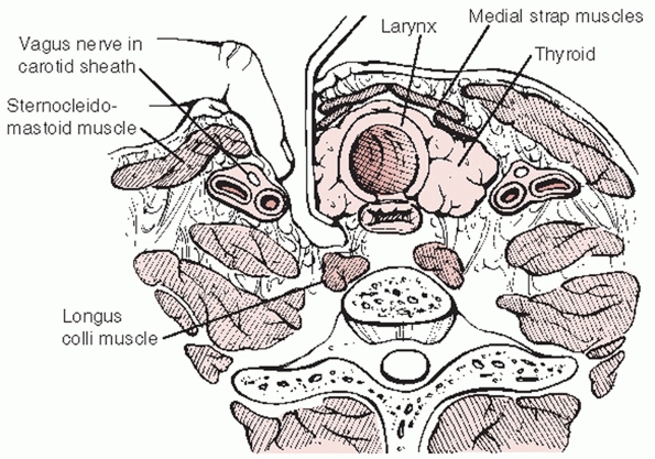
The anterior approach to the subaxial spine utilizes the interval plane
between the sternocleidomastoid (lateral) and anterior strap (medial)
muscles. The location of the incision can be determined by palpable
landmarks: the cricoid cartilage is at the level of the C6 vertebral
body, the thyroid cartilage is at the level of the C4-C5 disc space,
and the hyoid bone is at the level of the C3 vertebral body. Deeper,
the interval of dissection is between the carotid sheath laterally and
the trachea/esophagus medially (Fig. 42-26).
The alar and deeper prevertebral fascia are then swept away to reveal
the anterior surface of the cervical spine. The longitudinal fibers of
the ALL can be visualized spanning across the vertebral bodies and disc
spaces. In the traumatized spine, there is often hematoma and edematous
tissue overlying the injured segment. Disruption of the ALL or anterior
disc space can also be readily visualized during the exposure. A
left-sided approach is the authors’ preference, as the recurrent
laryngeal nerve is more consistently located within the carotid sheath
and therefore at lower risk of injury than with right-sided approaches.
decompression can be effected via discectomy or corpectomy
(vertebrectomy). The decision to perform one or the other procedure is
usually decided prior to surgery and is based on (a) the extent of bony
injury/vertebral body comminution and (b) the location of compressive
pathology based on imaging studies. Vertebral body fractures that
involve a large portion of the endplate or are substantially comminuted
are not optimal docking points for strut grafts or fixation points for
screws.
cervical disc that is compressing the neural elements. In some cases,
however, the herniation can be displaced rostral or caudad behind the
vertebral body. This can necessitate partial or full corpectomy of the
vertebral body to adequately and safely remove the disc fragment.
fragments can be removed piecemeal with a rongeur. The bone can
potentially be reused if a titanium mesh is implanted. Alternatively, a
high-speed burr can be used to remove the injured vertebral body. The
width of the corpectomy should be approximately 15 to 16 mm, however,
this should be determined by preoperative imaging as vertebral
dimensions and anatomy can vary. In cases of high-energy injuries, the
PLL can be disrupted. Thus, with
removal of the bony fragments, the underlying spinal cord is readily visible and should be protected at all times.
 |
|
FIGURE 42-26
Anterior approach to the subaxial cervical spine. The superficial interval is between the sternocleidomastoid muscle (lateral) and strap muscles (medial). Deep dissection is between the carotid sheath (lateral, which contains the carotid artery, internal jugular, and recurrent laryngeal nerve) and the trachea/esophagus. The alar and prevertebral fascia (deepest) are swept away to access the ALL, vertebral bodies, and disc spaces. |
In presence of a herniated cervical disc associated with dislocated
facet joints, one may elect to perform an anterior discectomy and
decompression prior to reduction. This can be performed in several
methods. A lamina spreader can be placed between the endplates to
distract the injured segments and unlock the dislocation (Fig. 42-27).
Care must be taken to avoid overdistraction, which may impart further
damage to the spinal cord. Alternatively, Caspar pins can be placed
into the vertebral bodies and used to lever the upper segment on the
lower segment without additional distraction. A lateral intraoperative
radiograph should be obtained to confirm reduction. Unreducible
dislocations may necessitate additional posterior surgery to achieve
reduction.
completion of the decompression, the superior and inferior endplates of
the defect should be flattened and lightly burred until punctate
bleeding is achieved. The corpectomy or discectomy site is then
measured for strut selection and contouring. Autograft or allograft
bone can be used to reconstruct the anterior column. Structural
autograft can be harvested from the anterior iliac crest. The graft
should be cut to match the length, width, and height of the defect. The
graft is then gently impacted into place between the vertebral bodies.
There should be an intimate fit between the graft and host bone.
Because many injuries are highly unstable and easily overdistracted,
axial compression, produced by pressing on the top of the head, can
help.
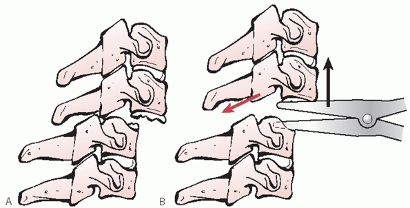 |
|
FIGURE 42-27
Open reduction of dislocated facets using an anterior approach. A laminar spreader can be used to distract and unlock the injured articular processes. |
cage. A potential advantage of a cage is that the corpectomy bone can
be recycled and packed inside, which may decrease the amount of iliac
crest autograft required. An additional, still theoretical, advantage
is possibly better incorporation and fusion because the cage can be
packed with primarily cancellous rather than cortical bone.73
The disadvantage of the cage is that it has minimal endplate contact
area, which may be a risk factor for subsidence into soft bone.
graft insertion, anterior stabilization should be performed. Anterior
cervical plates can be used to span discectomy or corpectomy defects.
Screw positioning and purchase are of critical importance. With the
plate well centered along the anterior vertebral bodies, holes are
drilled
through
the plate. The drill should always be angled approximately 10 to 15
degrees toward the midline to avoid violation of the vertebral artery.
In the sagittal plane, the holes should be parallel to or angled
slightly away from the fused endplate. Screw length should be
determined by preoperative imaging studies and confirmed by direct
measurement of the endplate/ vertebral body intraoperatively prior to
strut insertion. In total, four screws should be inserted, two into the
cranial vertebra and two into the caudal vertebra.
cervical traumatic instability, bicortical screws, which penetrated the
posterior vertebral body, were recommended. However, with more recent
advancements in screw and plate design, this is no longer routinely
performed by most surgeons. Fixed-angle screws, which lock into the
plate, offer equivalent, if not superior, biomechanical stability than
nonfixed bicortical screw-plate systems.116
Locking screws also prevent anterior screw migration. One disadvantage
of the first locking plate designs was that the angle that the screw
could be inserted into the plate was also fixed. Newer plate designs
enable variable angle screw placement with the choice of being rigidly
fixed to the plate or allowing a small degree settling.
For fixation of traumatic injuries, so-called dynamic plates are
usually not preferred. Such designs allow axial or vertical settling
during the postoperative period, either by slotted screw holes or a
piston-type mechanism within the plate itself. While these plates may
offer some advantages in degenerative cases, such as earlier graft
incorporation from increased stress-sharing, reconstruction after
fracture or dislocation is focused on achieving and maintaining maximal
stability. Rigid, nondynamic plates best achieve this goal. So-called
low-profile plates are thin, which is thought to lessen postoperative
swallowing complaints. While such devices are acceptable to augment an
anterior cervical disectomy for a degenerative process (such as a
herniated disc), thicker plates are preferred in the traumatic setting.
 |
|
FIGURE 42-28 Diagram depicting different plate types, including those with dynamic slotted holes (A), nondynamic (B), piston-type dynamic plates (C), and fixed or variable angle screws (D).
|
reviewed their results with one- or two-level fusions stabilized with
an anterior Senagas plate in 22 patients with lower cervical fractures
or dislocations. At 1-year follow-up, solid fusion was documented in
all cases with acceptable alignment. Garvey et al.100
found equally good results in 14 patients treated with anterior Caspar
plate fixation and fusion for subaxial cervical fractures and
dislocations. At an average follow-up of 30 months, no cases of
fixation failure had been observed. Goffin et al.104
reported 5- to 9-year follow-up results in 25 patients treated with
anterior fusion and plating for cervical fractures and dislocations.
Fusion was demonstrated in all cases by 1 year; plate fracture occurred
in one case. Paralleling the nontrauma literature, 15 of 25 (60%)
patients had evidence of adjacent segment degeneration, although this
did not correlate with clinical complaints. Laus et al.149
treated 32 lower cervical fractures or dislocations with anterior
surgery. Fusion was achieved in all patients by an average of 4.5
months. Neurological recovery of one to three Frankel grades was
observed in the 14 patients with an incomplete spinal cord injury and
no change in those with complete spinal cord injury or no neurological
deficit. Randle et al.197 also
documented their results with the Caspar plate with traumatic cervical
injuries; all patients achieved solid fusion by 6-month follow-up.
Brodke et al.42 compared anterior
and posterior surgery for unstable cervical spine fractures with spinal
cord injury. Neurological recovery was comparable in both groups. A 90%
fusion rate was achieved with anterior surgery; 100% with posterior
fusion; no differences in complaints of pain or maintenance of
alignment.
posterior approach to the cervical spine is a midline, extensile
approach that can be used to access as many spinal levels as necessary.
The dissection can be relatively bloodless if maintained between within
the avascular plane of the ligamentum nuchae, which separates the right
and left paraspinal muscles. Intramuscular hemorrhage and posterior
interspinous and supraspinous process ligament damage is often apparent
at the level of injury. It is important to maintain continuity of any
uninjured ligaments until the correct surgical level is identified as
to avoid unnecessary destabilization of other segments. Subperiosteal
dissection is started on either side of the bulbous, bifid spinous
process, continues down to the spinolaminar junction, and extends
laterally over the laminae. Lateral dissection should be taken only at
the levels to be fused. Accordingly, only the facet joints that will be
fused should be exposed, along with their corresponding lateral masses.
dissection along the posterior C1 ring to within 1.5 to 2.0 cm from the midline to avoid injury to vertebral artery (Fig. 42-17).
Importantly, the artery is located along the superior aspect of the C1
ring within a groove so that more lateral exposure of the ring can be
safely performed along the inferior aspect of the C1 ring. Exposure of
this region is often needed to insert lateral mass screws into C1.
Surgeons should note the presence of ponticulus posticus, which was
present in 16% of patients in one study.255
While this bony containment of the vertebral artery can offer some
protection during exposure, it should not be erroneously interpreted as
a starting point for C1 screw insertion (Fig. 42-18).
Exposure of the superior aspect of the C2 ring should be proceed with
caution to avoid inadvertent entry into the spinal canal, which is not
protected by ligamentum flavum. Bipolar cautery can be used to exposure
the C2 pedicle to preemptively cauterize the leash of veins in this
location. The C2 nerve root should be visualized as it lies along the
posterior surface of the C1-C2 joint. It usually needs to be retracted
superiorly or inferiorly to expose the posterior aspect of the C1
lateral mass. Alternatively, it can be ligated, although this will
result in anesthesia in portion of the posterior head.
majority of acute, traumatic, cervical injuries, posterior
decompression via laminectomy is not necessary. Canal compromise is
most frequently caused by dislocation, translation, or retropulsed
vertebral body fragments. In rare cases of anteriorly displaced
posterior arch fragments, a laminectomy would be indicated to directly
remove the offending compressive elements. This is not true, however,
in cases of acute spinal cord injury associated with multilevel
spondylotic stenosis or ossification of the posterior longitudinal
ligament, in which a posterior decompressive procedure might be
considered the procedure of choice if cervical lordosis has been
maintained.
If acceptable alignment is not obtained by closed methods prior to
surgery, direct intraoperative reduction maneuvers can be performed.
Reduction of an anteriorly displaced C1 ring (from C1-C2 ligamentous
instability, odontoid fracture, or hangman’s fracture) can be achieved
by pulling an intact C1 ring posteriorly under fluoroscopic guidance.
While a towel clip can be used, a sublaminar wire or cable inserted
underneath the C1 ring is equally effective (Fig. 42-29).
Posterior displacement can be more difficult to reduce. An anterior
force can be carefully delivered to the C1 ring, if intact. For
bayoneted odontoid fragments, a Penfield elevator can be inserted
posterolaterally around the spinal cord into the fracture site to lever
the proximal fragment over the inferior fragment (Fig. 42-30). As a last recourse, reduction can be performed using screws inserted into the occiput, C1, or C2.
Usually, the primarily goal of posterior surgery for subaxial cervical
injuries is reduction and/or stabilization. Open reduction of
dislocated facet joints can be performed using a posterior approach.
Cervical traction can facilitate intraoperative maneuvers by providing
distraction across the dislocated segments. If the spinous processes
are intact, they can be grasped with towel clips near their base to
flex and distract the injured joint. If the spinous processes are
fractured, then a Penfield 4 elevator or other small flat instrument
can be placed over the top of the superior articular process of the
lower level. Then, angling it caudally, the inferior tip of the
inferior articular process of the upper level can be levered up and
posterior back into position (Fig. 42-31). If
these maneuvers fail, then the tip of the superior articular process of
the lower vertebra can be resected using a burr or small Kerrison
rongeur (Fig. 42-32).
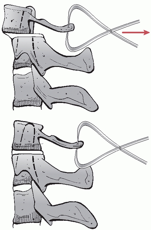 |
|
FIGURE 42-29
After posterior exposure has been performed, anterior displacement of the C1 ring can be reduced by delivering a posterior force via towel clips. Note that the ADI has been reduced in the lower figure. |
few published reports of the results of fixation and fusion for
traumatic injuries of the upper cervical spine. Available data is
discussed in more detail below categorized by injury type. Notably,
most available series detail use of classical techniques using wire
fixation, such as Gallie and Brooks fusion. Although it is widely
believed to be the current standard, the results of modern
instrumentation methods in the setting of upper cervical trauma have
not been well reported.
secured just below the external occipital protuberance with midline
screws. For stabilization of the occipitocervical junction, rods are
used to span from the occipital plate to variable angle screws inserted
into the C2 isthmus. Fixation across the atlantoaxial articulation is
usually performed using C1 lateral mass screws connected to C2 isthmus
screws using a variable angle-rod system. Fusion across these regions
is effected using autogenous bicortical iliac crest secured by braided
cables.
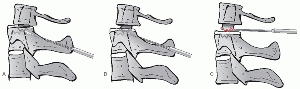 |
|
FIGURE 42-30
In challenging cases that do not reduce by conventional closed or open methods, a Penfield elevator can be carefully inserted posterolaterally into the odontoid fracture site (A). It should be advanced just beyond the anterior aspect of the proximal fragment under lateral fluoroscopy (B). The instrument is then levered superiorly to unlock the fracture fragments and restored alignment (C). |
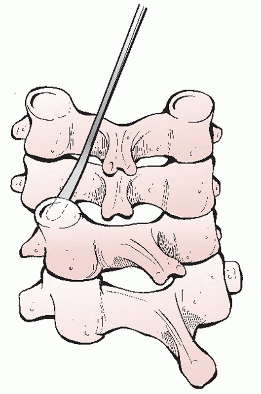 |
|
FIGURE 42-31
Open reduction of dislocated facets using a posterior approach. A Penfield 4 elevator (or other small, smooth, elevator) is inserted over the superior articular process. It is walked inferiorly to hook the inferior (dislocated) articular process. The elevator is then levered caudally to reduce the joint. |
The first forms of posterior cervical stabilization were wire-based
constructs, which are still commonly used today. The simplest form of
wire stabilization is interspinous process wiring. Using a drill bit or
a small (2- or 3-mm burr), a hole is created on either side of the
superior third of the spinolaminar junction of the upper vertebra.
Next, the hole is completed from side-to-side by puncturing the bone
with a towel or sharp bone clamp. One or more wires, or optimally a
braided-cable, is passed through the hole and then passed beneath the
spinous process of the lower vertebra. The wire or cable is then
tensioned. Alternatively, the wire can be passed through a hole in the
inferior third of the spinolaminar junction of the lower level.202
A triplewiring technique has also been described, which incorporates
fixation of corticocancellous struts on either side of the spinous
processes. The advantage of wiring techniques is that they are
a
relatively inexpensive method of posterior stabilization with nearly
equivalent restoration of stability as some lateral mass plating
systems.170
The disadvantages are that it cannot be used if a laminectomy has been
performed or in the presence of posterior element fractures.
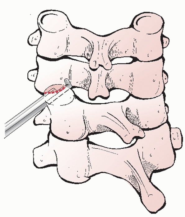 |
|
FIGURE 42-32
A Kerrison rongeur can be used to resect the superior aspect of the articular process if open reduction maneuvers are not successful. |
treated 162 patients with flexion injuries by posterior interspinous
process wiring and fusion. At 12-week follow-up using flexion-extension
views, fusion was achieved in 100% of cases. Of note, residual kyphosis
was present in 54 (34%) of patients, translational deformity in 14
(9%), or hyperlordotic deformity in 7 (4%) of cases. These data suggest
that although a high fusion rate can be achieved, that radiographic
maintenance of alignment is not as reliable.
cervical spine injuries. In this technique, a small hole is drilled
within the lateral mass at 90 degrees to the articular surface. The
wire is then passed through the lateral mass hole and subsequently
through a hole in a piece of corticancellous strut graft. The advantage
of this technique is that it can be performed with laminectomy or
posterior arch fractures. A disadvantage is stability is still
partially reliant on bone graft. In addition, passage of the most
inferior wire is across a joint that is not fused or included in the
construct. Improved stability may be achieved by wiring the facets to a
longitudinal rod or Luque rectangle.63
recent years. Lateral mass screws can be inserted using several
different techniques (Fig. 42-33). With the
Roy-Camille technique, orientation of the screw is more perpendicular
to the long axis of the spine. This can make fixation to a rod or plate
more facile, however with the sacrifice of a shorter screw length and
potentially greater risk of injury to the vertebral artery. The Magerl
technique offers the advantage of greater screw length with potentially
higher pull-out strength. While the vertebral artery may be less in
danger, the nerve might be more at risk as the screw tip is directed
toward the level of the disc space.
newest systems include variable angle titanium screws that are
connected to longitudinal rods (Fig. 42-34).
The advantages of these systems over lateral mass plates are that (a)
they are more forgiving of minor differences in medial-lateral and
proximaldistal variation of screw position and (b) enable optimal screw
placement to be determined by the patient’s anatomy or injury rather
than the location of the holes in the plate.
used posterior lateral mass screws and plates to treat 197 patients
with lower cervical spine injuries. Final radiographic follow-up
demonstrated that initial reduction and alignment was maintained in 85%
of cases. Nazarian and Louis179 used
posterior screws and lateral mass plates in 23 cases of cervical
fractures with excellent maintenance of alignment and fusion rates. In
a prospective, randomized controlled trial, Kwon et al.147
found that anterior plate fixation and posterior lateral mass fixation
resulted in comparable outcomes for unilateral facet fractures or
dislocations.
constructs to stabilize the cervical spine after traumatic injuries.
The ability to place screws in the optimal position followed by
fixation to an appropriately contoured rod is considered a major
advantage. In addition, individual screws and levels can be compressed
and distracted to achieve maximal correction and reduction.
medial to the hillock of the lateral mass in the coronal plane and
mid-way between the surfaces of the superior and inferior articular
process (Fig. 42-35). A 2-mm burr is used to
start the hole. Next, a hand drill is inserted into the starting hole,
angling laterally about 20 degrees and parallel to the facet joint in
the sagittal plane. This can be judged best by placing a thin, flat
instrument into the joint to be fused. Drilling proceeds carefully just
to, but not through, the second cortex, as bicortical fixation has not
been demonstrated to be of biomechanical advantage.190
length. In the authors’ experience, preoperative CT imaging is often
limited use in estimating screw length. In most cases, a 12-or 14-mm
screw can be inserted. Screw holes should be tapped, as the bone of the
lateral mass can be quite dense. The 3.5-mm screw is then inserted and
two-finger tightened. Attempts to overtighten screws can easily strip
the hole, which may necessitate placement of a rescue (4.0-mm) screw.
Too high or too low screw placement can risk breakout into the
articular surfaces. Too far lateral placement can fracture the lateral
mass, which may preclude adequate fixation at that level.
articular surfaces of the facets should be decorticated using a small
micro-curette prior to lateral mass plate or rod placement. A 3-mm burr
is then used to lightly decorticate the lateral masses. If screws have
been placed, it is important to not remove too much bone as this may
weaken the region surrounding the screw and lead to cut-out. If the
laminae and spinous processes are intact, then their posterior surfaces
should also be decorticated down to a bleeding surface. Cancellous bone
harvested from the posterior iliac crest is then packed inside the
facet joints. The lateral mass rods may then be placed. Additional bone
is laid over the posterior elements and lateral masses.
spinal injuries is that the need for postoperative external
immobilization is usually lessened or may be eliminated. However, this
should be evaluated on a case-by-case basis and strongly determined by
the quality of fixation achieved. In the authors’ practice, a rigid
cervical collar is prescribed for awake, alert patients who will be
ambulatory following surgery for 6 weeks. In multiplyinjured,
ventilator-dependent patients, an orthosis is avoided to facilitate
nursing and respiratory care. With rigid internal fixation, the patient
can be seated in a cardiac chair as tolerated to enhance pulmonary
toilet and clearance of secretions. If indicated, postoperative
antiembolic chemoprophylaxis can be started on postoperative day 4 or 5
so as to avoid an epidural hematoma. Prophylactic antibiotics are
continued for 48 hours.
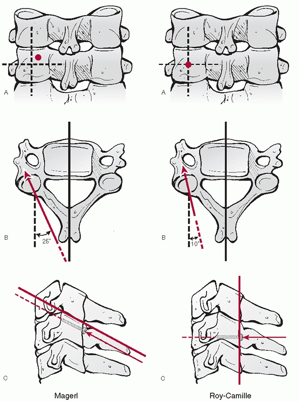 |
|
FIGURE 42-33 Magerl (left) and Roy-Camille (right) techniques of inserting lateral mass screws.
|
surgery is swallowing difficulty or dysphagia, which may occur in up to
50% of cases. Recurrent laryngeal nerve palsy, which presents with
dysphonia, occurs in approximately 4% to 5% of the time. Risk factors
include exposure below C5 and revision surgery. Horner’s syndrome is an
infrequent complication of the anterior cervical approach. It can occur
from damage to the sympathetic plexus that may occur from overzealous
retraction of the longus colli. It presents with ptosis, meiosis, and
anhydrosis. Hypoglossal, facial, and glossopharyngeal nerve injuries
can occur with high anterior approaches. Prior to closure of an
anterior neck wound, the esophagus should be inspected for tears.
Unrecognized tears, whether caused by the initial trauma or iatrogenic,
should be repaired primarily to avoid deep infection. Large traumatic
tears may sometimes require a rotational muscle flaps from the
sternocleidomastoid for coverage.
of a recognized intraoperative event such as a direct spinal cord
injury or posterior strut or graft displacement, a careful and detailed
examination should be performed by the same practitioner who had been
serially examining the patient preoperatively. It should be determined
if the new deficit is above, at, or below the level at which surgery
was performed and whether it represents a root or spinal cord injury.
Plain radiographs of the operated region should be obtained first to
see if catastrophic failure of the construct has occurred. If a second,
missed, noncontiguous spinal lesion is suspected, a full series of
cervical, thoracic, and lumbar spine films should be obtained
immediately. There should be little hesitation to obtain postoperative
CT or MRI. It is for this reason that the authors prefer to use
titanium instrumentation, which is MRI-compatible. Screw, strut, and
graft placement should be assessed to detect any impingement on the
spinal canal, nerve roots, or vertebral arteries. Hardware that appears
to be a likely cause of neural deficit should be removed in the
operating as soon as possible.
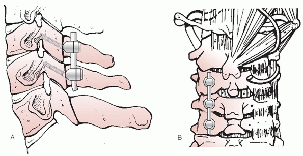 |
|
FIGURE 42-34 Side view (A) and posterior view (B) of a diagram depicting a variable angle posterior screwrod construct for stabilization of lower cervical spine injuries.
|
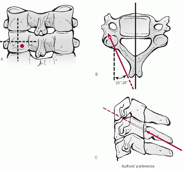 |
|
FIGURE 42-35
The authors’ preferred technique is a modified Magerl method. A starting hole is created with a 2-mm burr bit. Dividing the lateral mass into quadrants, it is located at the superolateral aspect of the inferomedial quadrant (A). The screw is then angled laterally about 20 to 25 degrees (B). In the sagittal plane, the screw path is kept perpendicular to the plane of the adjacent facet joint (C). This method allows placement of the screw within the mid-aspect of the lateral mass. Unicortical purchase is preferred. |
repaired primarily. It is the authors’ preference to use 6-0 Prolene in
a running locking pattern to achieve watertight closure. In cases of
large, irreparable injuries, as is common with burst fractures, a
fascial graft should be sewn into place. A wound drain should not be
placed in presence of a dural tear, and the patient should be covered
with an antibiotic that crosses the blood-brain barrier, such as
ceftriaxone, until all wound drainage stops. If a persistent leak
develops, a subarachnoid lumbar drain can be placed. If the leak does
not stop, the tear should be reexplored and repaired to avoid formation
of a spinalcutaneous fistula.
are wound infections. The rate does not appear to be significantly
higher in patients undergoing anterior cervical surgery who have a
preexisting tracheostomy.184 In general, posterior surgery appears to have a slightly higher rate of infection than anterior cervical surgery.
days after surgery and may be adequately treated with oral antibiotics
and local wound care. Wounds should be closely monitored, however. If
they do not appear to be responding to treatment, as evidenced by
increasing rubor, drainage, and pain, then early intraoperative
irrigation and debridement should be performed. Intraoperative cultures
are important in determining the most appropriate antibiotic regimen.
Well-fixed instrumentation and bone graft should be left in place to
maintain stability and promote eventual fusion. Aggressive, early
surgical debridement of deep infections can help avoid late onset
osteomyelitis, epidural abscess, meningitis, and catastrophic
instrumentation failure.
common late surgical complications. Symptomatic anterior pseudarthrosis
can be treated with repeat anterior surgery, or preferably posterior
instrumentation and fusion. Early hardware failure can be associated
with insufficiently stable constructs. Multilevel (3 or more)
corpectomies stabilized with anterior fixation alone have a high rate
of failure and should be routinely stabilized with posterior
instrumentation and fusion. Anterior graft or plate extrusion can lead
to swallowing difficulty or, more seriously, airway compromise. Late
hardware failure, such as screw breakage is often associated with
nonunion, which may or may not be symptomatic or require treatment.
and dissociations are the result of high-energy distractive injuries.
In essence, the injury can be likened to closed decapitation.
Accordingly, occipitocervical dislocations often results in death.2
Perhaps a result of their relative rarity, delayed diagnosis of these
injuries can result in catastrophic neurological decline. In a review
of 17 consecutive cases over an 8-year period, Bellabarba et al.22
documented that the diagnosis was made on the initial trauma lateral
radiograph in only two patients. Moreover, there was, on average, a
2-day delay in the diagnosis, which resulted in secondary neurological
decline in 5 of 17 (29%) of cases. Likewise, Govender et al.110 found that two of four cases were initially missed. In an early review of seven cases, Przyblski and Welch195
recognized the inadequacy of plain films for detecting occult
occipitoatlantal dislocation, extolling the vital role of CT and MRI.
dislocation have been proposed; however, the BAI and BDI, also known as
Harris’ rule of twelve, appear to be the most useful.35,108
A classification of occipitocervical dislocations has been proposed.
Importantly, some C1 or C2 fractures can functionally behave as an
occipitocervical dissociation, such as the case reported by Jea et al.132
in which an axially unstable type III odontoid fracture with
circumferential ligamentous instability occurred in a patient with
brainstem dysfunction and quadriparesis. Likewise, occipitocervical
dissociation can occur through the atlantoaxial joint.246
Type I injuries exhibit anterior displacement of the occiput in
relation to the C1 arch; type II have axial separation of the
occipitoatlantal junction; type III exhibit posterior displacement. Of
note, a variant of type II (classified as type IIb) involves axial
distraction through the atlantoaxial junction (Fig. 42-36).
 |
|
FIGURE 42-36
Classification of occipitoatlantal dislocations. Type I injuries exhibit anterior displacement of the occiput in relation to the C1 arch; type II have axial separation of the occipitoatlantal junction; type III exhibit posterior displacement. Of note, a variant of type II (classified as type IIb) involves axial distraction through the atlantoaxial junction. |
treatment has little, if any, role in the definitive treatment of
occipitocervical dislocations or dissociations. Halo vest
immobilization is most often used as a temporary means of stabilizing
or reducing injuries until surgery can be safely performed.
Longitudinal traction is contraindicated.
successful treatment of a patient with a distractive atlantoaxial
injury in a halo vest.51 The patient
was reportedly without complication at 5-year follow-up. Others have
reserved nonoperative treatment for select patients who are
neurologically intact.130 However, the authors did not offer a reliable method for selecting appropriate candidates.
improved dramatically in recent years. In the past, the only fixation
method available relied on structural iliac crest autogenous bone graft
that was wired to the occiput, C1 and C2. As it was not rigid fixation,
halo vest immobilization was routinely used. Following this, wiring
contoured rods to the vertebrae represented an improvement in
mechanical stability but still did provide sufficient fixation to
obviate external immobilization. Introduction of plate-screw fixation
was a precursor to modern fixation techniques. The so-called “Y” plate
allowed screws to be placed directly into the occiput, C1, and C2 to
provide truly rigid fixation, although fatigue fracture of the
relatively thin plate was a common complication.
connected to polyaxial screws, which can be inserted into C1 through
C7, have resulted in extremely stable and versatile constructs. Some
systems allow independent insertion of an occipital plate and cervical
screws, which are then connected using a contoured or articulating rod.
While not technically possible with older fixation techniques that
relied on hooks and wires, modern systems can even allow localized
occipital-atlantal fixation via the use of C1 lateral mass screws as
distal anchoring points to preserve atlantoaxial rotation.9
Similarly, another group reported success with isolated atlantoaxial
fixation in a patient with type IIb occipitocervical dislocation,87
presumably to preserve C0-C1 motion. Although good outcomes with these
selective fusion techniques have been reported in select cases, it is
technically demanding and requires careful evaluation of the stability
of the unfused C1-C2 or C0-C1 articulation.
dislocations and dissociations should be considered the conservative
treatment option. These injuries are grossly unstable, are primarily
ligamentous, and have little chance of healing with external
immobilization alone.
clinical studies documenting the superiority of one method of
occipitocervical fixation over another. Biomechanical data demonstrate
that screw-based constructs are stronger than hook or wire based
constructs. In one study, constructs using C2 pedicle screws or C1-C2
transarticular screws were stronger than those in which use sublaminar
wires or hooks were used for distal fixation.187
operative treatment of occipitocervical injuries using modern
instrumentation, Bellabarba et al.22
reported a 100% fusion rate in 17 patients followed for a mean of 26
months. Importantly, one patient declined neurologically immediately
following surgery, which was the results of intraoperative
misalignment. Urgent revision surgery led to dramatic neurological
improvement. Overall, the average ASIA motor score improved from 50 to
79. Furthermore, the number of patients with an ASIA D or E increased
from 7 preoperatively to 13 postoperatively.
occipitocervical dislocation is stabilization with a plate-screw-rod
construct and fusion with iliac crest bone graft. Contemporary cervical
instrumentation systems allow placement of an occipital plate using
midline screws inserted into the thickest portion of the bone for
maximal strength.118,257 Lateral wings facilitate mating an articulated rod from the occipital plate to C1 and/or C2 lateral mass screws.
inspection of preoperative images should be carried out. First, the
direction of occipital dislocation should noted, as this will determine
the direction of reduction forces. A lateral radiograph of the skull,
or ideally a sagittal CT of the head, should be used to measure the
thickness of the occiput and location of the external occipital
protuberance (EOP). The EOP is an important intraoperative landmark. In
addition to having the thickest bone, it also demarcates the
approximate level of the transverse sinus. Bicortical drilling can risk
injury to this intracranial venous sinusoid, which can lead to
intracranial hemorrhage. If MRI is available, the transverse sinus can
be directly visualized and its position relative to the EOP noted. In
general, screws should be kept distal to the EOP.
(i.e., pars) screws as the distal fixation points. Paramedian CT images
should be inspected to ensure that the C2 pars is intact and of
sufficient size to accept a 3.5-mL screw. The location of the vertebral
artery foramen should also be noted, as this can affect the screw
trajectory. With a low-riding vertebral artery foramen, the screw can
be inserted parallel to the sagittal plane (Fig. 42-37).
With a high-riding foramen, the screw must be kept short or angulated
medially to avoid injury to the vertebral artery. This decision should
be made preoperatively, as intraoperative fluoroscopic images are
unlikely to allow adequate visualization of the foramen.
tube should be inserted using a fiberoptic scope to avoid unnecessary
movement of the head and neck. The head should be manually stabilized
at all times. In absence of a complete spinal cord injury, motor and
sensory evoked potentials are used, with baseline signals obtained
prior to the flip. Next, the patient is carefully logrolled into the
prone position. It is the authors’ preference to use a standard
electric operating table with transverse chest and thigh rolls. Moving
the head and torso as a unit is paramount to avoid further displacement
through the injury site. With all pressure points protected, the arms
are tucked at the patient side and the knees flexed about 30 degrees.
About 20 degrees of reverse Trendelenburg (i.e., head above feet) can
decrease
venous congestion, which may lessen intraoperative blood loss. The head
is positioned in a Proneview Helmet. No traction is applied.
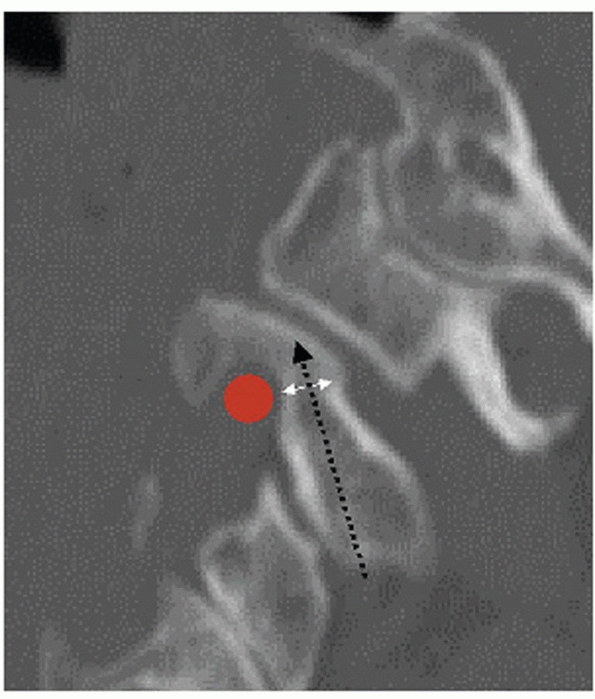 |
|
FIGURE 42-37 Careful inspection of a paramedian image through C2 reveals the bony corridor (double white arrow) through which a screw can be placed (black dashed arrow).
A high-riding vertebral artery foramen (red circle) can substantially narrow this interval and, in some cases, preclude insertion of a C1-C2 transarticular screw. |
as possible following prone positioning. Reduction of the occipital
condyles within the superior articular surfaces of C1 should be
confirmed. Gentle reduction maneuvers can be attempted to improve
alignment, including axial loading the head to reduce occipitocervical
distraction. Last, an AP view is obtained to ensure adequate
visualization of the C1-C2 joint and odontoid process, important
landmarks for C2 screw orientation.
posterior midline approach is performed to expose a large portion of
the occiput, the central 2 cm of the C1 ring, and C2 as described
earlier. Traumatic disruption of the dura is not uncommon between the
occiput and C1 or C1 and C2. These should be repaired with 4-0 Neurilon
suture, if possible, or sealed with a synthetic dural patch. Although
it should not be violated, the C2-C3 facet joint must be visualized as
it is an important landmark for C2 screw insertion.
of a sublaminar cable around C1. This enables better control of C1
during reduction. Following exposure of the posterior aspect of the C1
ring, a small angled curette is used to subperiosteally dissect around
the anterior aspect of the posterior C1 ring. After an ample
soft-tissue sleeve is created, the leader of a threaded double-loop
cable is bent into a curve and passed around the C1 ring. Because the
interval between C1 and C2 is usually larger than the interval between
the occiput and C1, it is the authors’ preference to pass the cable
from proximal to distal. Care must be taken not to inadvertently pass
the leader too far into the spinal canal. Once the leader loop is
visualized in the C1-C2 interspace, it is retrieved using a small nerve
hook. The cables are then pulled through, leaving equal portions above
and below the C1 ring.
using a 2.5-mL high-speed burr. The location of the starting hole is
just lateral and superior to the inferolateral aspect of the C2-C3
joint (Fig. 42-38). An AP odontoid view
confirms that the starting points are aligned with the mid-aspect of
the C1-C2 joint. Next, the C-arm is positioned for a lateral view. The
proximaldistal location of the starting point should be adjusted so
that it is centered within the mid-aspect of the C2 pars. A 2.5-mL
drill bit (for a 3.5-mL screw) is advanced under hand power into the C2
pars. The tip of the drill bit should be directed toward the superior
aspect of the pars to avoid the vertebral artery foramen on the lateral
view. Provided adequate reduction and alignment can be maintained, a
few degrees of capital flexion can help achieve this angle.
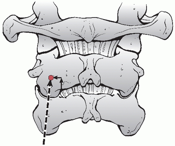 |
|
FIGURE 42-38 The starting point (black dot) and trajectory (dashed arrow) for a C2 isthmus screw. The starting point lies just superior and lateral to the medial aspect of the C2-C3 joint.
|
the drill can be maintained in a perfectly sagittal or slightly
medialized orientation. Lateral deviation risks injury to the vertebral
artery. Overzealous medial angulation risks violation of the spinal
canal. As it is a unicortical screw, tactile feedback is an important
component to avoiding cortical breakout. After the drill bit has been
inserted to a sufficient depth, the hole is probed, measured, and
tapped. The screw is then inserted under lateral fluoroscopic guidance.
With both C2 screws in place, an AP view should confirm that they are
directed toward to the mid-aspect of the C1-C2 joint.
borders of the EOP should be marked. An appropriately sized plate
should be obtained and placed into its prospective location. Ideally,
the plate should be placed so that the most proximal screw hole is as
close but still inferior to the EOP. Using a marking pen, the site of
the proximal screw is delineated. The plate is then removed to allow
easier preparation of the initial hole. The 2.5-mL burr is used to
create a starting hole, followed by drilling with sequentially longer
bits. Most systems provide a method to drill at controlled increments
of 2 mL, starting from 6 mL. While bicortical screw fixation is
strongest, unicortical fixation near the EOP is safer and has
acceptable strength.118 It is the
authors’ preference to predetermine the screw length based on
preoperative CT measurements. The hole is then tapped to the same
depth. With the first occipital screw path
prepared,
the plate is placed into position and the screw inserted. The plate is
held in ideal position, which has a tendency to rotate with screw
tightening. This single screw will hold the plate in a secure position
while the other screws are inserted.
connect the plate to the C2 screws. After it is cut to length, it is
inserted into the tulip screw heads. Lock nuts are loosely inserted
into the tulip heads, while a final reduction is performed. Reduction
relies on manipulation of the proximal and distal segments. A tonsil
clamp can be used to grasp the occipital plate to control the head; a
towel clip can be placed on the C2 spinous process for distal control.
Alternatively, the sublaminar C1 cable can be used to deliver a
posterior force. AP translation can be held in a corrected position
while an assistant tightens the rods to the tulip heads. A lateral view
should confirm acceptable reduction of the condyles on C1. In a final
step, minor adjustments in flexion-extension can be made through the
rod articulations before they are final tightened.
harvested. It is contoured to fit between the occipital base and the
superior aspect of the C2 laminae and spinous process. Ideally, the
bone graft should also contact the C1 ring. After decorticating the
contact areas on the occiput, C1, and C2, the graft is held in place
with the sublaminar cable (Fig. 42-39).
occipitoatlantal fixation is that it obviates the need for
postoperative halo vest immobilization, allowing use of a cervical
collar only. Wound and drain care is as described earlier. AP, lateral,
and open mouth radiographs are obtained postoperatively. The patient is
mobilized as tolerated. Follow-up radiographs are obtained at 2 weeks,
3 months, 6 months, and yearly thereafter to assess the integrity of
the construct and fusion.
Although sometimes challenging, the surgeon should be confident that he
can adequately identify important bony landmarks on the lateral view,
including the basion and odontoid tip. The tip of the odontoid should
be in relative close proximity to the basion. It is less reliable to
judge AP translation by examining the relationship between the C1 ring
and the occiput. However, a change in the relative positions might be
gauged by comparing preoperative and intraoperative images.
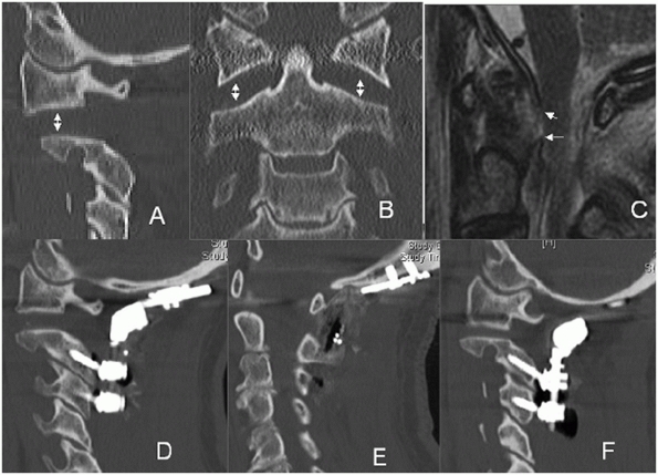 |
|
FIGURE 42-39 CT images of a patient with a type IIb occipitoatlantal dislocation (A,B), showing widened C1-C2 lateral mass joints. A sagittal MRI image demonstrates discontinuity of the tectorial membrance (white arrows, C).
Although anatomic alignment could not be achieved, the patient was adequately reduced and stabilized using an occipital plate and screws placed into C2 and C3 (D-F). |
also impart greater risk for dural penetration. If cerebrospinal fluid
(CSF) is encountered during occipital hole preparation, bone wax can be
used to control fluid escape. Ultimately, insertion of the screw
effectively seals the leak in a watertight fashion.
bone graft. In contrast to older techniques, stability is not
contingent upon the integrity of the bone graft. If this occurs, the
sublaminar cable can be removed and graft repositioned to span C0 to C1
and C1 to C2. An overlay cable can be passed around the rods and
posterior to the graft to hold it in position.
mechanisms. Stable fractures, such as Anderson and Montesano type I and
II and Tuli et al. type 1 and 2A fractures probably occur from axial
impaction of the head onto the cervical spine. Unstable injuries
obligatorily have ligamentous disruption and thus probably result from
distraction of the head from the spine.
reported a case in which a hypoglossal nerve palsy developed 6 weeks
after bilateral occipital condyle fractures. Similarly, Urcolo et al.230
treated a patient that developed glossopharyngeal and vagus nerve
palsies that were not diagnosed until 4 months after sustaining an
occipital condyle fracture.
Fracture fragment size, apposition, and gapping is best assessed on
coronal and sagittal CT reconstructions. Plain films unreliably
demonstrate occipital condyle fractures.
used their experience with six patients in addition to previously
published findings of 20 patients with occipital condyle fractures to
develop a classification scheme for these injuries. By their
description, type I injuries are impaction fractures, type II injuries
are basilar skull fractures that involve the condyle, and type III
injuries are displaced avulsion fractures (Fig. 42-40).
Importantly, the authors highlight the higher potential for instability
with type III compared to type I and II fractures. Accordingly,
nonoperative treatment was recommended for type I and II fractures,
while occipitocervical stabilization and fusion was recommended for
type III fractures.
proposed an additional classification for occipital condyle fractures
based on a review of 93 injuries. Stable, nondisplaced injuries were
classified as type 1, those that were displaced but stable with no
ligamentous injury were type 2A, and those that were displaced and
unstable with ligament injury were type 2B. Importantly, the
investigator highlighted the importance of CT and MRI in distinguishing
stable from unstable injuries. In a recent study of 76 cases, Aulino et
al.17 found it difficult to distinguish between type 1 (stable) and type 2A (unstable) fractures using the Tuli et al.229 system.
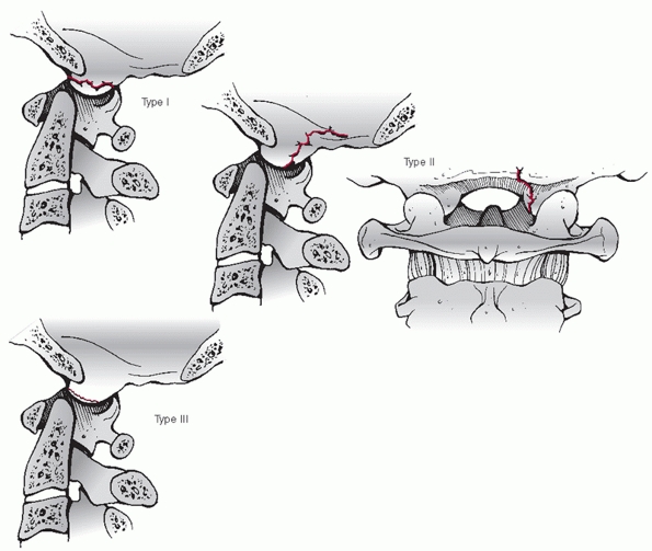 |
|
FIGURE 42-40
Classification of occipital condyle fractures. Type I injuries are impaction fractures, type II injuries are basilar skull fractures that involve the condyle, and type III injuries are displaced avulsion fractures. |
A rigid cervical collar worn for 8 to 12 weeks is usually sufficient
for Anderson and Montesano type I and II injuries. Because of the
potential for instability with type III fractures, halo vest
immobilization or operative treatment is indicated. Beyond the
distinction between injury types in classification systems, the authors
rely more heavily on inspection of the integrity of the tectorial
membrane on MRI to differentiate stable from unstable injuries. In the
authors’ practice, disruption of the tectorial membrane is a relative
contraindication for nonoperative treatment.
reported results of nonoperative treatment of occipital condyle
fractures. There were five type III, three type II, and two type I
fractures. Successful healing was documented in all 10 patients.
unstable injuries. The authors’ criterion for instability is disruption
of the tectorial membrane as assessed on sagittal T2-weighted MRI.
Using available classification systems, Anderson and Montesano type III
and Tuli et al. type 2B fractures are described as unstable, although
they are not always associated with tectorial membrane disruption. In
cases that are functionally craniocervically unstable, occipitocervical
stabilization and fusion is indicated.
unstable occipital condyle fracture are similar to those documented for
craniocervical dislocations and dissociations. Among a series of 95
patients with occipital condyle fractures, Hanson et al.119
reported good results with occipitocervical fusion or halo vest
immobilization in the 12 displaced, unstable injuries. Caroli et al.50 also reported successful healing in five patients surgically treated for unstable occipital condyle fractures.
condyle fractures with a rigid cervical collar. In those cases with MRI
evidence of tectorial membrane disruption, occipitocervical
stabilization and fusion, as detailed earlier, is performed.
with occipitocervical ligamentous injury without substantial
misalignment.30 Thus, a high index
of suspicious for occult ligamentous instability must be maintained,
regardless of the fracture type. Similarly, Caroli et al.50
warned of the potential for occult instability with occipital condyle
fractures based on their experience with five cases and an analysis of
116 cases reported in the literature.
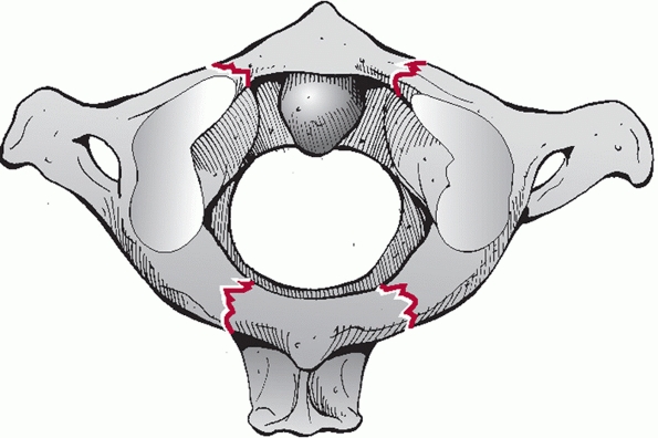 |
|
FIGURE 42-41 Diagram of the classic Jefferson fracture, depicting bilateral fractures in the anterior and posterior C1 ring (white arrows).
|
Simple posterior ring fractures are thought to occur from
hyperextension, as the C1 ring can be impinged between the occiput and
C2. The mechanism of injury with Jefferson (burst) fractures is
generally presumed to be axial load that results in tensile failure of
the C1 ring. Using a finite element analysis, Bozkus et al.40
supported that axial compressive loads can lead to sufficient strain
within the C1 ring to produce characteristic fractures. This, they
concluded, “proves that the Jefferson fracture is a burst” injury.
However, alternative mechanisms have been suggested. In a biomechanical
study on human specimens, Beckner et al.21
found that pure lateral tensile loads can result in two fracture lines
(i.e., three fracture fragments). Although spinal cord injury is
infrequent with isolated injuries, unstable fractures from high-energy
mechanism may be at greater risk.151
First, it is not mechanically possible to fracture the C1 ring in only
one location. In an illustrative example, this would be like trying to
break a pretzel in one spot. Thus, the minimum number of fracture sites
is two; therefore, the minimum number of fragments is two. Posterior
arch fractures are the simplest and most benign pattern; two fractures
in the C1 ring occur posterior to the lateral masses. While these are
of little mechanical significance on spinal stability, their
recognition is important if C1 sublaminar wiring is planned.
However, the mechanical significance of a single burst fracture in the
anterior and posterior ring is the same. As long as the left and right
sides of the ring have been dissociated, the potential for injury to
the C1-C2 facet joint and the transverse ligaments is present. The
exact location of the fractures can vary substantially, with some
injuries occurring through the lateral masses.
burst fractures is the integrity of the transverse ligaments. The
transverse ligament is disrupted in tension with lateral displacement
of the fragment fragments, which can lead to C1-C2 instability.151
Outside of direction inspection on MRI, which can be difficult and
unreliable, the integrity of the transverse ligament is usually deduced
based on the amount of lateral overhang of the C1 lateral masses on C2.
As detailed in the section entitled Radiographic Injury Description,
this measurement is made on the open mouth view. Combined left and
right lateral overhang greater than 7 or 8 mL implies transverse
ligament injury.
fractures) has varied. However, in the absence of superseding injuries,
most advocate nonoperative treatment in the vast majority of cases.
Isolated C1 ring fractures might not require formal immobilization,
provided that adequate flexion-extension views do not demonstrate
instability. Stable Jefferson or burst fractures can be treated
nonoperatively in a rigid cervical collar for 8 to 12 weeks. Unstable
fractures can be reduced in halo traction, followed by placement in a
halo vest. Importantly, flexion-extension views should be obtained
after the fracture is healed to rule out C1-C2 instability.
found that traction could reduce fracture displacement from 12.3 mL to
3.9 mL, which was maintained with fracture healing. Lee et al.152
retrospectively reviewed results of nonoperative treatment with a rigid
cervical collar in 16 patients with stable Jefferson fractures,
reporting adequate healing and no C1-C2 instability at 1-year follow-up.
effective treatment of residual C1-C2 instability following Jefferson
or C1 burst fractures. In the acute setting, methods that rely on C1
sublaminar cables/wires, such as Brooks or Gallie techniques, are not
technically possible because of fractures of the posterior arch. If the
ring fracture has sufficiently healed, these can be performed.
methods have become more popular. Provided that adequate fracture
reduction can be achieved, transarticular C1-C2 screws can be used to
stabilize the instability. If preferred or if adequate reduction cannot
be obtained, C1 lateral mass and C2 isthmus screws can be used.
cases, often after the failure of nonoperative measures. This is most
commonly defined as C1-C2 instability following nonoperative treatment
in a collar or halo vest.
atlantoaxial stabilization and fusion with transarticular screws was
used as a salvage treatment following unsuccessful halo vest
immobilization in five of eight patients with unstable Jefferson
fractures. The other three patients were primarily treated with
surgery. Solid fracture healing was reported in all cases at final
follow-up.
anterior osteosynthesis of C1 ring fractures. The exact indications of
this technique are unclear, as it does not directly address transverse
ligament disruption.
osteosynthesis of the C1 ring to treat Jefferson fractures through a
transoral approach.205 It is unclear, however, how this treatment would address residual C1-C2 instability from transverse ligament disruption.
fractures nonoperatively in patients who are neurologically intact. For
simple posterior arch fractures, a hard collar is worn for
approximately 2 weeks to allow initial pain and spasm to subside.
Flexion-extension views are then obtained to confirm mechanical
stability of the spine. For burst and Jefferson fractures with less
than 7 to 8 mL of lateral overhang on open mouth view, a rigid cervical
collar is worn for 12 weeks. Although a confirmative CT scan is not
routinely obtained, adequate fracture healing is presumed to be present
at this time. Flexion-extension views are then obtained to rule out
occult C1-C2 instability.
Jefferson fractures with more than 7 to 8 mL or lateral overhang are
presumed to be unstable. In the authors’ practice, unstable injuries in
patients without neurological deficit are treated first with
longitudinal traction delivered via a halo ring. An open mouth view is
obtained to confirm adequate reduction. Following a short period of
sustained traction (3 to 5 days), the patient is placed in a halo vest
and mobilized. Importantly, traction is maintained until the vest is
secured. Prior to releasing the traction, the wheel nuts on all four of
the upright struts are maximally lengthened to pretension the unit.
obtained. While some redisplacement from axial settling is expected,
excessive (greater than 5 or 6 mL) is not ideal. If this occurs, the
patient is placed back in traction for an additional few days after
which mobilization in the halo vest is once again attempted.
after Jefferson/burst fractures, and thus should be considered a true
complication. Regardless, its clinical significance must be considered.
Instability occurs from transverse ligament disruption, which, by
itself, has been demonstrated to allow a maximum of 5 mL of widening of
the ADI. The alar ligaments are usually not disrupted with Jefferson
fractures, as the odontoid process is not displaced relative to the
anterior foramen magnum (where the ligaments insert). Once the C1 ring
fractures have healed, and assuming that no concomitant cervical
fractures are present, the injury should be treated as atlantoaxial
instability (see
below).
Greater than 5 mL of widening of the ADI implies a more substantial,
and potentially dangerous, degree of instability that places the spinal
cord at risk. In such cases, a C1-C2 fusion using C1 lateral mass
screws and C2 isthmus screw is performed as previously described.
likely occurs from an abrupt flexion moment that results in shear
forces of C1 on C2. It is a ligamentous injury that involves at minimum
the C1-C2 facet capsules and the transverse ligament with or without
alar ligament disruption. Anatomical studies suggest that transection
of the transverse ligament alone allows widening of the ADI to a
maximum of 5 mL, with the alar ligaments preventing further
displacement.89,216
Sectioning of the latter was necessary to produce ADI’s greater than 5
mL. Distraction injuries through the atlantoaxial joint and instability
following atlas fractures are considered elsewhere in this chapter, as
they have distinctly different mechanisms of injury and treatment.
measuring the ADI. Normally, this interval is no greater than 2 to 3 mL
in adults. In an awake, cooperative patient who is neurologically
intact, flexion-extension films can be obtained to detect occult
instability in a patient with a normal ADI. Flexion-extension films may
not be necessary in a patient with a grossly widened (greater than 5
mL) ADI as disruption of both the alar and transverse ligaments can be
inferred. For those with initial ADI’s that have a somewhat widened (3
to 5 mL) or asymmetry of the ADI (i.e., angulation of the C1 ring on
the odontoid results in a wide ADI superiorly but normal ADI
inferiorly), flexion-extension views can be useful in distinguishing
the magnitude of instability.
initial trauma survey, one should be comfortable assessing the ADI on
sagittal and axial images. An axial view through the C1 ring or a
midsagittal reconstruction can be used to measure the ADI. MRI is not
useful for ADI measurement as bony detail is often not clear. However,
high-quality axial images can be used to directly inspect the
continuity of the transverse ligament, while sagittal and coronal
images can reveal the alar ligaments. Increased signal within the C1-C2
facet joint or between the atlas and odontoid process can also suggest
injury.
magnitude of instability, the neurological status of the patient, and
the age of the patient. Isolated transverse ligament injuries usually
do not result in gross instability. In a patient who is neurologically
intact, nonoperative treatment in a collar or a halo vest can be used,
provided the ADI can be held in a reduced position. The transverse
ligament can heal, particularly if it is attached to a small avulsion
fracture. Younger patients have a greater chance of healing. Although
not hard and fast rules, nonoperative treatment is relatively
contraindicated in patients with ADI’s above 5 mL, spinal cord injury,
or in whom a halo vest is not advised (e.g., pulmonary injury, cranial
fracture).
treatment, traction can be an effective method of reducing sagittal
C1-C2 instability.252 The force
vector should be directly slightly posteriorly; thus, if cranial tongs
are used, pins should be located just anterior to the external auditory
meatus. Importantly, care must be taken to rule out axial instability
after initial placement of weight (5 to 10 pounds). Although its only
initial radiographic abnormality may be a widened ADI, circumferential
ligamentous C1-C2 instability behaves functionally as a craniocervical
dissociation that can exhibit substantial, and potentially dangerous,
axial displacement with traction weight.36
fracture usually consists of posterior atlantoaxial stabilization and
fusion. A variety of method can be effective, including Gallie or
Brooks techniques, transarticular screws, C1 lateral mass-C2 isthmus
screws, or combinations thereof.
injury, surgical treatment should be strongly considered regardless of
the degree of instability. Patients with ADIs greater than 5 mL should
also undergo C1-C2 fusion. Symptoms such as occipital headaches, neck
pain, or C2 neuralgia in conjunction with late instability are also an
indication for surgical stabilization.
instability have included patients with varied injury types. In the
authors’ review, a dedicated study of one or more surgical methods for
the treatment of ligamentous C1-C2 instability without fracture could
not be found. Overall, fusion rates appear to be highest with more
stable methods of fixation, such as C1 lateral mass screw-C2 isthmus
screw or C1-C2 transarticular screw stabilization compared with
wire-based constructs, such as Gallie or Brooks techniques.43,98,134
sagittal atlantoaxial instability surgically with posterior
stabilization with C1 lateral mass-C2 isthmus screws followed by fusion
with tricortical iliac crest bone graft stabilized with a cabled passed
sublaminarly at C1 and underneath the spinous process of C2. This
technique is described in the section entitled posterior surgery.
note the location of the vertebral artery foramen of C2 to determine
screw trajectory and length. The proximity of the internal carotid
artery to the anterior aspect of C1 can be noted an axial MRI images,
as this structure can be endangered with bicortical C1 lateral mass
screws.
motor and sensory-evoked potentials have been obtained, the patient is
positioned prone on a standard electric operating table on transverse
chest and thigh rolls. Reduction of the C1-C2 joint can be achieved and
maintained by neck extension and gentle traction attached to the head
of the table.
the posterior C1 ring along its central 2 cm and the C2 laminae and
spinous processes. Before exposure of the C1-C2 joints and C1 lateral
masses, which can be quite bloody, the C2 isthmic screws are inserted.
Bipolar cautery is used to dissect superiorly along the posterior
cortical surface of the C2 pars/pedicle until the C2 nerve root is
encountered. This is retracted inferiorly, allowing exposure of the C1
lateral mass. At no time does dissection proceed above the C1 ring
along its lateral aspect for fear of injuring the vertebral artery. In
the authors’ preferred technique, the posterior C1 arch is not used as
a landmark for screw insertion.
posterior arch. Pulling on this cable anchor allows excellent control
and complete reduction of the ADI. Next, C2 isthmus screws are inserted
under fluoroscopic guidance as described earlier in the section
entitled Occipitocervical Dislocations and Dissociations. Importantly,
this is performed prior to exposure of the C1 lateral masses for two
reasons. First, the dissection usually involves entry into an
epidural/epineural venous plexus, which can lead to a continuous bloody
ooze. Since insertion of the C2 screw does not require exposure of this
region, it is performed first to minimize total blood loss. Second, a
wellplaced C2 isthmus screw can be used as a medial-lateral landmark
for the C1 screw insertion point. As mentioned previously, a C2 screw
is ideally directed toward the midaspect of the C1-C2 joint.
the C1 posterior arch, within the mid-aspect of the lateral mass.
Provided adequate exposure of the posterior cortical surface has been
achieved, a Penfield elevator can be used to retract the C2 nerve root
inferiorly. The C1-C2 articular surfaces can usually be clearly seen,
as the joint capsule has been disrupted by the trauma. A lateral view
is used to confirm that the Penfield is resting along the posterior
margin of the lateral mass. Next, a 2.5-mL burr is used to create a
starting hole, followed by preparation of the screw path with a 2.5-mL
drill bit under hand power. The bit is angled medially about 10 degrees
to access the thicker bone in this region. It is the authors’
preference not to penetrate the far cortex.
of the screw shaft will lie outside the bone. A depth gauge is
inserted. However, instead of measuring the intraosseous path, the
depth gauge is adjusted to be aligned with the tulip head of the C2
screw. Most systems have long, terminally threaded screws with solid,
smooth proximal shafts to avoid irritation of the C2 nerve root. The
appropriate length screw is inserted and its position checked on AP and
lateral views.
to the screw heads on either side. To ensure complete reduction, the C1
cable can be used to pull the C1 ring posteriorly while an assistant
tightens the locking nuts. A lateral view should confirm reduction with
traction removed. A tricoritcal piece of iliac crest autograft is then
cabled in place over the decorticated posterior surfaces of C1 and C2.
internal fixation, it is the authors’ preference to maintain the
patient in hard cervical collar for 8 to 12 weeks. If the patient has
multiple injuries and will be in the intensive care unit for a
prolonged period, the collar can be removed.
achieving a nearly perfect reduction prior to incision.
Intraoperatively, reduction is aided by the C1 sublaminar cable. The
surgeon must ensure, however, that the C1 ring is intact and
that a nondisplaced odontoid fracture is not present. Aggressive force
on the C1 cable can lead to displacement of an unrecognized fracture.
can range from neurological decline, dural tear, pseudarthrosis, to
wound infection. Complications specific to surgical treatment of this
injury include malreduction and overdistraction of the C1-C2 joint from
overly aggressive intraoperative treatment.
rare in adults, with few dedicated series reporting the incidence or
outcomes of this injury. Lukhele et al.162
reported results of a series of 10 patients with atlantoaxial rotatary
dislocation caused by trauma or infections. Traumatic injuries most
likely occur from a combination of lateral flexion with forced
rotation. Patients who were diagnosed early were effectively treated
with traction and external immobilization; surgical treatment that
included occipitocervical fusion was required in those who presented
late. Rotatory dislocation after displacement of an odontoid fracture
has also been reported97 (Fig. 42-42).
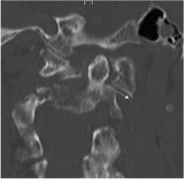 |
|
FIGURE 42-42
Coronal CT reconstruction of a patient with rotator subluxation following a C2 odontoid fracture. Note that one C1-C2 lateral mass joint appears laterally subluxated (white arrow), while the contralateral joint alignment is maintained. |
They postulated that the neck injury occurred during shoulder impact
after a fall. While the clavicle injuries were detected acutely, the
cervical dislocation diagnosis was delayed resulting in fixed
deformity. Neurological injury is uncommonly associated with C1-C2
rotatory instability. Occipital neuralgia, however, is common.90
missed. In one study, the delay in diagnosis ranged from 4 weeks to 2.5
years.162 Asymmetry of the C1-C2
joints on initial trauma CT scans is usually attributed to head posture
during the exam. Barring other sites of injury, axial CT images through
C1-C2 obtained with the head maximally rotated to the left and right
will definitely demonstrate a fixed rotatory subluxataion or
dislocation.
denotes four injury types. Type I is a rotatory deformity without
gapping between the odontoid process and the anterior C1 arch. Type II
denotes gapping of 3 to 5 mL, implying transverse ligament disruption.
Type III denotes gapping measuring more than 5 mL, implying transverse
and alar ligament disruption. They also proposed a type IV as being a
posteriorly translated rotatory dislocation; however, this only
occurred in one patient in whom the odontoid process had been eroded by
rheumatoid arthritis. Interestingly, a recent report documented a case
of posterior rotator dislocation of the C1 ring over the odontoid
process, although this functionally was more akin to a traumatic
occipitocervical dissociation.
be treated nonoperatively. Reduction is achieved via traction and is
usually successful in acute cases.90
Once reduction is achieved, a decision must be made regarding the
method of immobilization, which can vary from cervical orthosis to halo
vest immobilization. Wetzel and La Rocca247
recommended an external orthosis for type I injuries, a cervicothoracic
orthosis (CTO) for type II injuries, and halo vest for type III
injuries.
nonoperative treatment of rotatory instability included primarily
pediatric patients with postinfectious lesions. In these reports,
nonoperative treatment is generally successful, provided a reduction
can be achieved. The duration of immobilization after reduction has
varied from 6 weeks to 3 months.90,247
associated with a spinal cord injury, gross dynamic instability (as
detected on rotational CT), and in those patients who have failed
nonoperative measures.
posterior stabilization and fusion. The relative benefits,
disadvantages, and results of the various method of posterior C1-C2
fusion are detailed elsewhere in this chapter.
rare injuries includes several steps. Regardless of the acuity, closed
reduction with cranial tong traction is attempted. If reduction is
successful, then posterior C1-C2 fusion is performed using C1 lateral
mass-C2 isthmus screws and iliac crest. If reduction cannot be
achieved, open relocation of C1 and C2 is performed through a posterior
approach followed by fixation and fusion.
is not clear. In a biomechanical study in cadaveric specimens, Doherty
et al.72 concluded that type II
odontoid fractures are likely caused by lateral or oblique forces,
while type III fractures are caused by extension forces.
traumatic force that causes odontoid fractures. In the elderly,
forehead lacerations and periocular ecchymosis are commonplace, as the
usual mechanism is a frontal impact that causes neck hyperextension.
which holds that the distinction between type II and III fractures is
the absence or presence, respectively, of fracture extension into the
superior articular surface of C2. The group further divides injuries by
fracture obliquity, displacement, and comminution, which are generally
believed to affect treatment decision-making and outcomes. While they
found reasonable reproducibility among seven spine surgeon who reviewed
52 cases, the system has not been clinically validated in a prospective
study. Vieweg et al.242 found that more than 5 mL of fracture displacement was a risk factor for nonunion with nonoperative treatment.
for most odontoid fractures. Nonoperative treatment of odontoid
fractures can include use of a soft collar, rigid cervical orthosis, or
a halo vest.
a method of symptomatic treatment for low-demand, elderly patients with
odontoid fractures. A rigid cervical collar can be used to treat
nondisplaced type I, II, and III fractures. Some believe that a halo
vest is more appropriate for nondisplaced type II fractures because of
the reported high nonunion rate. A halo vest can be used to maintain
reduction and alignment in displaced type II and III fractures.
fractures. The treatment algorithm included nonoperative treatment in
all cases except those patients in whom fracture alignment could not be
maintained by an external orthosis, odontoid fracture was associated
with a transverse ligament disruption, Type II odontoid fractures with
displacement more than 6 mm, or high-grade hangman’s fractures. Of
note, type II odontoid fractures were identified as particularly
problematic, as they had a 28.4% nonunion rate.
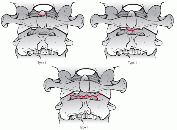 |
|
FIGURE 42-43
Anderson and D’Alonzo classification system for odontoid fractures. Type I fractures are small avulsion fractures from the tip of the dens. Type II fractures occur through the so-called waist of the odontoid process. Type II fractures occur through the cancellous bone of the C2 vertebral body. |
means of realignment a displaced or angulated odontoid fracture. This
method can be used as a prelude to either operative or nonoperative
treatment. Traction reduction can be used in patients with and without
neurological injury. Contraindications to traction include evidence of
occipitocervical dissociation or cranial fractures at the proposed pin
sites of a halo ring or tongs.
closed reduction and realignment of odontoid fractures. In one
retrospective review,206 a technique
of bivector traction was described, presumably to allow correction of
both angular and translational deformity of posteriorly displaced
fractures.
traumatized spine. In cases of unrecognized, occult occipitocervical
dissociations that occur concomitantly with noncontiguous cervical
fractures for which traction might be indicated, inadvertent
overdistraction at the craniocervical junction can result.134
Thus, it is recommended to routinely obtain an initial lateral cervical
radiograph immediately following placement of 5 pounds of traction.
for displaced or nondisplaced type II and type III odontoid fractures.
Traction via a halo ring can be used first to reduce the fracture,
which can be subsequently converted to halo vest immobilization. Halo
vest immobilization may not be ideal in patients with fractures that
cannot be reduced or a reduction cannot be maintained. Although related
to odontoid fractures specifically, there are several other
contraindications for halo vest treatment, as listed earlier, such as
cranial fractures at the proposed pin sites or severe chest trauma.
documented results of operative and nonoperative treatment of odontoid
fractures. In short, nonoperative treatment with a halo vest was
utilized in cases in which reduction could be achieved and maintained,
while operative treatment with posterior C1-C2 fusion was selected for
irreducible fractures. Of the group with fractures initially displaced
less than 5 mL, 11 of 17 (64.7%) were successfully treated by closed
means while 6
of
17 (35.3%) were treated with immediate C1-C2 fusion. Of the group with
fractures displaced more than 5 mL, 13 of 20 (65%) were successfully
reduced with a halo vest, although 2 patients developed a nonunion, and
7 of 20 (35%) underwent surgery.
fractures, with no clear superiority of one technique over another.
Options include osteosynthesis with an anterior odontoid screw,
posterior C1-C2 fusion, and anterior C1-C2 fusion.
of an odontoid fracture in a younger patient include fracture
displacement greater than 5 mL, fracture angulation greater than 10
degrees, neurological deficit, or multisystem trauma in which case
external immobilization with either a collar or a halo device would not
be well tolerated. The indications for operative treatment in elderly
patients (older than 65 to 70 years old) are less clear, as it appears
that nonoperative treatment of substantially displaced fractures can
yield satisfactory outcome in low-demand individuals, provided there is
ample space available for the spinal cord and the patient is
neurologically intact.124 Others use more aggressive indications, recommending surgery for nearly all odontoid fractures in elderly patients.
according to technique. The results of individual operative methods are
discussed below.
general surgical indications outlined earlier, anterior odontoid screw
fixation requires additional consideration of several factors.
Concerning fracture pattern, transverse fractures or oblique fractures
in which the fracture line runs from anterosuperior to posteroinferior
can be stabilized by an odontoid screw. Importantly, odontoid screws
are contraindicated in fractures that pass from anteroinferior to
posterosuperior, as compression will worsen fracture displacement (Fig. 42-44).
Nearly anatomical reduction is required for odontoid screw insertion.
As screw trajectory is a critical factor, screw insertion may not be
technically possible in patients with barrelshaped chests or pronounced
cervical kyphosis. Odontoid screws are most appropriate for type II
fractures. They should not be considered for type I and most type III
fractures. Some type III fractures that pass through the superior
aspect of the C2 vertebral body (closer to the odontoid waist) are
amenable to screw fixation.
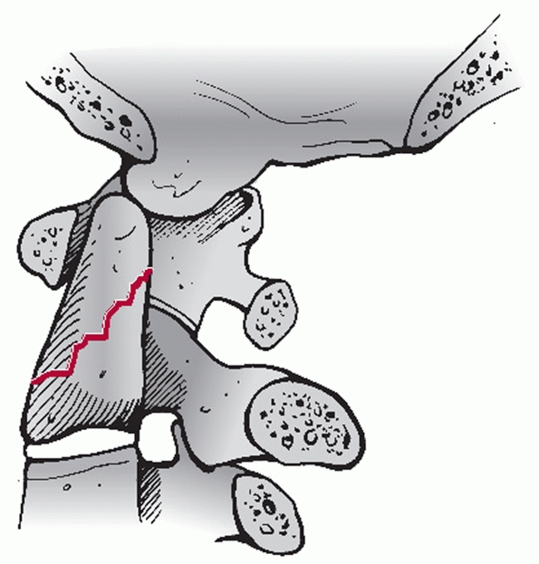 |
|
FIGURE 42-44
Oblique fracture of the odontoid process that runs from anteroinferior to postersuperior is not amenable to odontoid screw fixation. |
claimed successful stabilization in nine cases of Type II odontoid
fractures treated with a single anterior screw construct. Bhanot et al.25
found anterior screw fixation resulted in fracture union with minimal
compliations in 16 of 17 patients. Both single- and double-screw
techniques can be used to stabilize type II odontoid fractures.
ElSaghir and Bohm80 reported a 100%
healing rate in 30 patients who underwent two-screw fixation. In
another retrospective review of 26 cases of acute type II odontoid
fractures treated with single-screw anterior fixation,218 25 patients exhibited a solid fusion.
C2 specimens, one study found that a single anterior odontoid screw
provided only half the strength of the intact bone.72 Grazio et al.114
found single- or double-screw fixation of a simulated odontoid fracture
produced comparable stability as posterior C1-C2 wiring. Aebi et al.3
reported a higher (12%) nonunion and major complication (24%) rates
than previously documented with anterior screw fixation of 17 type I
and II odontoid fractures. However, the investigators thought that
these rates were comparable to those documented for C1-C2 arthrodeis.
While effective for stabilization of the fracture, Verheggen and Jansen239
reported hypomobility in 11 and frank C2-C3 fusion in 2 of 18 patients
who underwent anterior screw fixation, which they attributed to injury
of the C2-C3 disc space during surgery.
purported to increase the accuracy of odontoid screw placement.
However, Battaglia et al.19 found
computer-assisted fluoroscopic navigation produced comparable accuracy
as standard fluoroscopy in 22 cadaveric cervical specimens undergoing
odontoid screw placement. In a radiographic CT study of 92 normal
odontoid processes, Nucci et al.185 concluded that two 3.5-mL screws could be safely contained in 95% of cases.
use of a variable pitch screw was more stiff than a lag (partially
threaded) screw for fixation of simulated type II odontoid fractures.
McBride et al.168 found a single
4.5-mL headless Herbert screw was stronger than two 3.5-mL AO lag
screws for fixation of simulated type II fractures.
stabilization and fusion can be performed in any case in which surgery
is an indicated treatment for an odontoid fracture. There are a variety
of methods by which a surgeon may stabilize and fuse this segment, some
of which require particular consideration. Sublaminar wiring
techniques, such as the Brooks or Gallie methods, can accentuate
posteriorly displaced fractures. Transarticular screw fixation requires
reasonable reduction of the fracture so that there is enough overlap
between the C1-C2 lateral masses through which to pass the screws. C1
lateral mass-C2 isthmus screws is the most versatile fixation method,
as it does not require
anatomical reduction and, in fact, can be used to help reduce fractures.
provide clinical data, in vitro biomechanical studies have compared the
strength of commonly used surgical constructs. In the presence of a
simulated dens fracture, one study showed that anterior or posterior
C1-C2 transarticular screws and C1-C2 lateral mass fixation provided
comparable stability while C1 lateral mass-C2 intralaminar screw was
less stable.148 Of note, the
addition of posterior sublaminar wiring provided additional stability
only for posterior C1-C2 transarticular screw constructs.
widely used, some advocate anterior stabilization and fusion of C1-C2
in select cases. Purported indications include failure of a posterior
fusion, soft-tissue injury over a proposed posterior surgical incision
site, or contraindication to prone positioning.
performed an anterior C1-C2 fusion for concomitant odontoid and C1 ring
fractures in one patient, reporting solid fusion at 4-month follow-up.
Vaccaro et al.235 used this technique as a salvage option following a failed posterior C1-C2 fusion in a patient.
odontoid fractures in elderly patients remains unclear as the results
of varied treatment methods has varied. In a retrospective study of 29
patients aged 66 to 99 years old,12
anterior screw fixation and nonoperative management exhibited a high
failure rate, defined as postoperative complications or nonunion. In
contrast, the authors found that all patients treated by posterior
atlantoaxial fusion achieved bony union. Supportingly, Campanelli et al.48
reported good outcomes with transarticular fixation and posterior C1-C2
fusion in seven geriatric patients with displaced type II odontoid
fractures.
reported no cases of neurologic decline and a significantly higher rate
of complications with halo use in patients older than 60 years.
However, there was not statistical difference in functional outcome
between operative and nonoperative treatment in patients older than 60
years. Some have suggested that posterior displacement is a risk factor
for nonunion with conservative treatment, however, these data were not
controlled for age.143
be challenging. Both anterior and posterior approaches have been
advocated. Based on a series of eight patients with odontoid nonunions,
Blauth et al.29 developed a
classification system to help guide treatment. Type I are so-called
stable nonunions that are not substantially displaced. Type II are
stable but grossly displaced. Type III are unstable nonunions, and type
IV are posttraumatic os odontoideum. The authors recommended posterior
transarticular C1-C2 fixation for unstable fractures that can be safely
reduced.
reported successful results with a transoral injection of
polymethylmethacrylate into the nonunion site of a patient with an
unhealed dens fractures. Importantly, they used image-guidance for this
procedure.
fractures, the authors’ treatment algorithm utilizes a variety of
treatment techniques. Notwisthstanding those cases that represent
occult occipitocervical dissociation, type I fractures are treated in a
hard cervical collar for eight weeks, after which flexion-extension
views are obtained to confirm stability. Of note, isolated type I
fractures are exceedingly rare, with the authors’ having encountered
only one case in their practice. Most nondisplaced type II fractures in
young patients are treated in halo vest, while most nondisplaced type
III fractures are treated a hard cervical collar. Displaced type II and
III fractures in young patients are first reduced using halo traction.
Once acceptable alignment is obtained, a halo vest is fitted in
patients who are neurologically intact and in whom there are no
relative contraindications to vest wear (e.g., substantial pulmonary
trauma). Following reduction, it is the authors’ preference to perform
a posterior C1-C2 stabilization and fusion in those with neurological
deficits. One of the most challenging situations is a nonreducible
odontoid fracture. In such cases, an open reduction is performed
through a posterior approach utilizing C1 lateral mass and C2 isthmus
screws. An elevator inserted into the fracture site can be used to aid
the reduction (see Figure 42-30).
Preoperative planning for C1 and C2 screw placement has been detailed
elsewhere in this chapter. If the fracture cannot be reduced by closed
means, the direction of displacement and fracture morphology should be
noted. For example, posteriorly displaced fractures with bayonet
apposition will require distraction and anterior forces delivered to
the C1 lateral mass screws. The converse would be appropriate for an
anteriorly bayoneted fracture.
monitoring is used for this procedure. After intubation, the patient is
carefully log-rolled into the prone position on a standard electric
operating table fitted with transverse chest and thigh rolls. Traction,
preferably through a halo ring, is maintained via an apparatus attached
to the head of the table. Once the patient is in position, a lateral
fluoroscopic view is obtained to confirm that reduction was maintained.
If not, a gentle closed reduction maneuver can be performed using
weights or manual traction. Angulation can be corrected by extending or
flexing the head. With reduction on the lateral view confirmed, an AP
view is obtained to ensure adequate visualization of the C1-C2 joints
and odontoid process.
for insertion of the C1 and C2 screws and C1 sublaminar cables have
been described earlier. Once these are in place, the reduction of the
fracture should be confirmed on the lateral view.
cervical collar is maintained for 3 months. Radiographs are obtained
immediately after surgery and at 2 weeks, 3 months, 6 months, and 1year
after surgery.
anatomic reduction is easily obtained and maintained in most cases,
intraoperative reduction maneuvers may be necessary in recalcitrant
cases. This can be performed using the screws. Distraction between the
screws can help unlock interdigitated fracture fragments. Anterior
forces can be delivered to C1 or C2 by using the screw inserter device.
Posterior reduction forces are readily applied by using the C1
sublaminar cable. If necessary, a number three or four Penfield
elevator can be inserted into the fracture site help reduction. Under
lateral fluoroscopic guidance, the elevator walked along the medial C2
pedicle wall. Attentively holding the elevator’s handle lateral to
avoid impingement of the spinal cord, the tip of the instrument is
angled into the fracture site (see Figure 42-30).
With posteriorly displaced fractures, the Penfield is angled superiorly
while it is angled inferiorly for anteriorly displaced fractures. Once
it has engaged the fracture site, it may be necessary to gently tap the
instrument until the blade has reached the anterior aspect of the
displaced fragment. Next, the elevator is levered superiorly or
inferiorly for posteriorly or anteriorly displaced fractures,
respectively. This maneuver should apply direct distraction to the
fracture fragments. While maintaining the Penfield elevator in place,
anterior or posterior reduction forces are applied to finalize the
reduction. With the rods already in place, the locks nuts are tightened
to maintain the alignment. Importantly, a final lateral view should be
obtained with the traction weight removed to confirm that the reduction
is being maintained by the instrumentation.
variety of approach and instrumentation-related complications that can
occur with this surgical technique. Although C1 lateral mass-C2 isthmus
screw constructs are among the strongest methods to stabilize the
atlantaxial joint, instrumentation failure can occur. Pseudarthrosis
can results from insufficient stabilization or poor bone graft
technique. Neurological decline can occur during reduction maneuvers,
overzealous dissection around the anterior portion of the posterior C1
ring, or screw misplacement.
In a postmortem examination of 34 corpses following judicial hanging,
James et al.131 found only three
cases in which a characteristic hangman’s fracture was present, while
the remaining 27 had no fracture at all. In an even more semantical
critique, Nijima182 objected to the term because it is the “hanged man” and not the hangman (i.e., executioner) who sustains the fracture.
fracture has been presumed to be a flexion force. However, recent
biomechanical evidence suggests that varying fracture patterns are the
result of different forces imparted to the C2 pars with the neck in
different postures.224
In this system, a type I is a minimally or nondisplaced with no
evidence of translation or angulation and thus no substantial injury to
the C2-C3 disc space. Type II fractures are characterized by both
angulation and translation and presumably occur from an extensions
mechanism. They incur substantial injury to the C2-C3 interspace. In
contrast, type IIa fractures occur via a flexion mechanism and are
characterized by marked angulation with minimal translational
deformity. Type III fractures include any C2 pars fracture associated
with a dislocation of the C2-C3 facet joint (Fig. 42-45).
added to the classification by describing the type Ia fracture, which
refers to those injuries in which a portion of the posterior C2
vertebral body is in continuity with one of the pars fracture
fragments. Noting a higher than incidence of neurological deficit among
their six patients, they attributed this to canal compromise that can
result from posterior displacement of the posterior arch-posterior
vertebral body fragment complex in contrast to the usual
canal-expanding fracture pattern.
examined the epidemiology of hangman’s fractures from a single center
in Singapore. Detecting 33 injuries over a 13-year period, they
reported a male predominance with 63.6% being the result of traffic
accidents. The most frequent types of fractures were type I, followed
by type II and type III. Twenty of 33 had no neurologic deficits, with
no clear predilection for one fracture type.
nonoperatively. Most type I injuries are effectively treated in a
cervical collar. Type Ia fractures have a high healing rate and are
also well treated in a cervical orthosis. Type II fractures, being
inherently less stable, are best treated by traction followed by halo
vest immobilization. Type IIa fractures should not be placed in
traction, as this can accentuate the deformity. Reduction is achieved
by extension and compression delivered via a halo vest. Importantly,
neurological deficit (although rare) is a relative contraindication to
conservative management, while facet dislocation is an absolute
contraindication to nonoperative care.
reported good results using a Philadelphia collar to treat 39 patients
with hangman’s fractures with less than 6-mm displacement. From a
recent systematic review of previously published literature, Li et al.156
concluded that most hangman’s fractures can be adequately treated by
nonoperative methods, with surgical stabilization reserved for cases in
which dislocation or substantial instability is present, such as type
III and some type IIa fractures.
reported the results of traction followed by early halo vest
immobilization in 31 patients with type II and IIa hangman’s fractures.
Acceptable alignment was achieved and maintained in 21 of 27 Type II
and all four type IIa fractures. In the other six cases with type II
injuries, the fracture displaced in the halo vest and required traction
to be reapplied. Attempting to analyze the injury characteristics
of
the latter cases, the authors found that all had initial fracture
angulation of 12 degrees or more. Regardless of the late displacement,
reapplication of traction was successful in these cases.
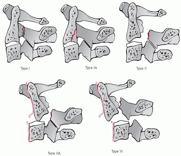 |
|
FIGURE 42-45 Classification of C2 hangman’s fractures (traumatic spondylolisthesis).
|
not clear, as there are proponents of anterior fusion, posterior
fusion, and osteosynthesis without fusion. In an in vitro biomechanical
study, found that posterior C2-C3 lateral mass fixation was stronger
than anterior C2-C3 plating, while the latter was stronger than direct
fixation of the C2 pars with a screw.74 Unanswered by this study is how strong a construct needs to be to be clinically successful.
surgery can be performed for type II, IIa, or III fractures. Reduction,
stabilization, and fusion of the C2-C3 facet joint are required for
type III fractures. Akin to anterior odontoid screw fixation, type II
and IIa fractures that can be adequately realigned can be treated via
osteosynthesis with a C2 pedicle screw, provided the patient has
amenable anatomy.
reported use of lag screws inserted into the C2 pars in a patient who
developed anterior displacement while in a halo vest. In a recent
report, Rajasekaran et al.196 used intraoperative image guidance to insert C2 pedicle screw to treat a hangman’s fracture. Similarly, Taller et al.221
successfully used C2 pedicle screws inserted with CT-guidance to treat
10 patients with hangman’s fractures. In a comparatively larger series,
Verheggen and Jansen240 documented
good radiographic and clinical results in 16 patients with type II,
IIa, and III fractures treated with C2 pedicle screw fixation.
fractures are amenable to anterior surgery if nonoperative treatment is
not possible or unsuccessful. Type III fractures require reduction of
the C2-C3 joint prior to stabilization, which usually requires a
posterior approach. As the C2 articular processes are not in continuity
with the C2 body, anterior reduction maneuvers are difficult.
effective in five patients in whom nonoperative treatment failed. At
follow-up ranging from 3 to 28 months, a 100% fusion rate was reported.
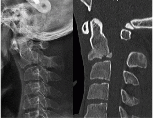 |
|
FIGURE 42-46 Lateral radiograph (left) and sagittal CT image (right)
of a young man treated in a halo fixator for a type II hangman’s fracture. Although there was substantial loss of reduction, he remained neurologically intact and without neck pain at final follow-up. |
with type I and Ia fractures using a hard cervical collar, provided no
neurological deficit. Patients with type II fractures are first reduced
in halo-based traction. After reduction has been adequately achieved,
the halo vest is affixed. Radiographs should be repeated at regular
intervals to ensure the acceptable reduction has been maintained (Fig. 42-46). As described by Levine and Edwards,153
patients with type IIa fractures are immediately placed into a halo
vest to allow reduction via compression and extension of the neck. Type
III fractures are treated with early posterior open reduction and
fixation using lateral mass screw fixation of C2 and C3. Importantly,
the C2-C3 disc space must be carefully assessed following facet
reduction, as persistent deformity in this region can be present that
may require incorporation of C1 in the posterior construct.
Alternatively, staged anterior C2-C3 fusion and stabilization can be
performed to avoid loss of C1-C2 movement.
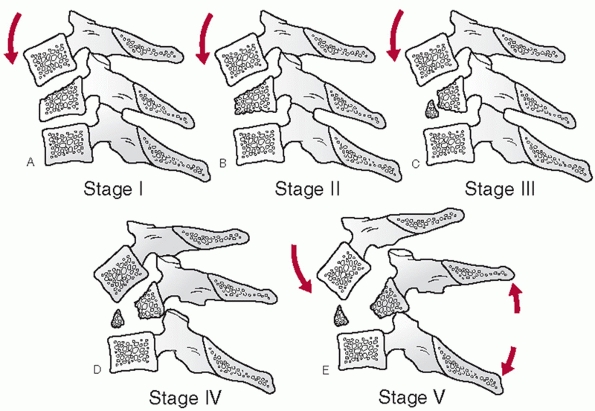 |
|
FIGURE 42-47 The five stages of compression flexion injuries.
|
spinal injury should ideally be based on a system that is
comprehensive, clinically prognostic, aids in treatment
decision-making, and is user-friendly, reliable, and reproducible.
Fulfilling all, or even some of these qualities, is a difficult task
that, at the time of this writing, has yet to be achieved by any
available classification system for any orthopaedic injury. Regardless,
there have been classification systems proposed for description of
subaxial cervical spinal injuries that are worth reviewing. While there
is lack of agreement on which is the most useful, the Allen and Ferguson7 mechanistic classification is among the most well-known, and as such, will be discussed in greatest detail (Fig. 42-47).
and dislocations to develop a classification system based on deducing
the mechanism of injury. Injuries were organized into one of the
following groups: compressive flexion, vertical compression,
distractive flexion, compressive extension, distractive extension, and
lateral flexion. Within each group, injuries were divided into grades
of severity. In this retrospectively developed system, the likelihood
and extent of neurological injury was related to the group and severity
of injury, however, this has not been validated prospectively since its
development.
forces produce injury, (b) the vectors (or direction) of these forces
can be deduced from radiographs, (c) the amount of energy relates to
the severity of injury, (d) injuries can be organized into groups based
on the force vectors and (e) they can be further subdivided based on
the energy of trauma.
The injury is speculated to occur first by flexion of the spine through
the facet joints. The anterior column (vertebral body) becomes
increasingly compressed and shortened. Eventually, the PLC fails, noted
by interspinous gapping and local kyphosis. With further energy, the
facet joints will fail, leading to translational deformity. The
distinguishing radiographic features of each stage should be
understood. It should be noted that the stages build upon one another,
so that, for example, stage 3 lesions also demonstrate the features
described for stages 1 and 2.
-
CF Stage 1: Blunting of the anterosuperior vertebral body margin
-
CF Stage 2: Beak-appearance of the anterosuperior vertebral body margin, a sagittal vertebral body split may also be present
-
CF Stage 3:
Oblique primary fracture line that extends from the anterior vertebral
body to the inferior endplate. (This has been subsequently described by
other authors as a so-called tear-drop fracture.92) -
CF Stage 4: In addition to stage 3 features, posterior translation of the upper vertebra measuring less than 3 mm
-
CF Stage 5:
Posterior translation of the upper vertebral measuring 3 mm or greater,
facet gapping, indicating anterior and posterior ligamentous injury
Vertical compressive (VC) lesions are thought to arise from primarily
axial loads to the cervical spine. While this is the authors’
description, the final stage of the injury may result from flexion or
extension vectors, which ultimately produce posterior or anterior
ligamentous injury, respectively (Fig. 42-48).
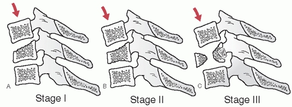 |
|
FIGURE 42-48 The three stages of VC injuries.
|
-
VC Stage 1: Central superior or inferior endplate fracture
-
VC Stage 2:
Superior and inferior endplate fractures, sometimes with vertebral body
fracture lines that give the appearance of a quadrangular fracture
fragment -
VC Stage 3:
Vertebral body comminution, with or without retropulsion of fragments
(This has been by others as a burst-type cervical fracture), with or
without kyphotic (late flexion type) or translational (late extension
type) deformity
Distractive flexion (DF) injuries are thought to occur from primarily
flexion injury vectors that rotate about an axis anterior to the
vertebral body. Thus, distraction and failure of the posterior
ligaments can occur without significant vertebral body fracture. In
this injury group, increasingly higher stages does not always
correspond to increasing amount of instability (Fig. 42-49).
-
DF Stage 1:
Facet subluxation, gapping of the spinous process ligaments, indicating
failure of the PLC, with or without some blunting of anterosuperior
vertebral body (like CF stage 1) -
DF Stage 2: Unilateral facet dislocation, usually PLC is intact, rotational deformity
-
DF Stage 3: Bilateral facet dislocations, 50% translation of upper vertebral body on lower one
-
DF Stage 4: Close to 100% translation of upper vertebral body on lower one, apperance of a so-called floating vertebra
They are postulated to start with compression of the posterior elements
without failure of the anterior ligaments. Further injury leads to
failure of the anterior/posterior ligaments.
-
CE Stage 1:
Posterior arch fracture that may be facet, pedicle, or lamina fracture,
with or without rotation that can result in mild anterior translation.
(These are more commonly referred to as lateral mass fractures.) -
CE Stage 2: Bilateral lamina fractures, can be multiple levels
-
CE Stage 3:
Bilateral lamina, facet, pedicle fractures without vertebral body
displacement. Although admittedly “hypothetical… having not been
encountered” in their review, the injury may be described as a floating
lateral mass fracture -
CE Stage 4: As for CF stage 3, with partial anterior vertebral body displacement
-
CE Stage 5: As for CF stage 3, with 100% anterior vertebral body displacement
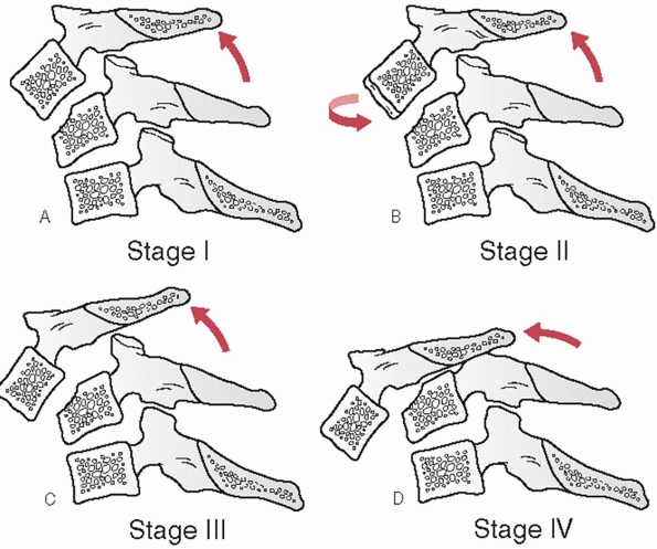 |
|
FIGURE 42-49 The four stages of DF injuries.
|
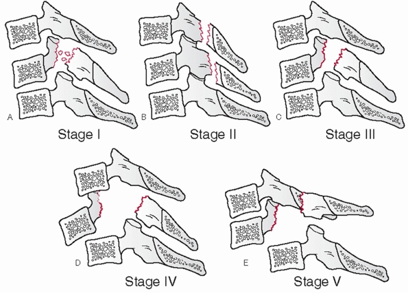 |
|
FIGURE 42-50 The five stages of CE injuries.
|
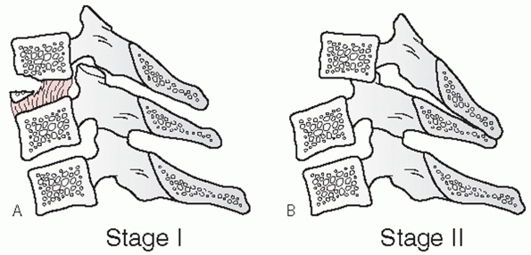 |
|
FIGURE 42-51 The two stages of DE injuries.
|
Distractive extension (DE) injuries, like DF injuries, demonstrate
substantial ligamentous injury in lower stages. Initial failure is
through the anterior ligaments (Fig. 42-51).
-
DE Stage 1:
Abnormal widening of the disc space, may or may not be avulsion
fractures of the anterior vertebral body margin, no posterior
translation -
DE Stage 2: DF stage 1 plus posterior translation
flexion (LF) injuries occur by compression on one side of the spine.
With further energy, the contralateral side can fail under tension.
-
LF Stage 1: Unilateral uncovertebral vertebral fracture or asymmetric vertebral body compression
-
LF Stage 2:
Vertebral body or posterior arch fractures with lateral translation or
unilateral facet gapping, coronal angular deformity is noted on an AP
radiograph
system is the most frequently cited and used classification for
subaxial cervical spine injuries. Despite this, it has not been
validated, retrospectively or prospectively, since its publication in
1982. Intra- and interobserver reliability has not been tested, to the
authors’ knowledge, and the significance of the injury groups on
treatment decision-making is not yet clear.
found facet dislocations, tear-drop vertebral body fractures, and
anterior translational injuries at the C3-C4 segment in football
players injured during a witnessed axial loading mechanism to the head
and cervical spine. According to Allen et al.,7
these would have had to occur from distractive flexion, compressive
flexion, and either compressive extension or vertical compressive
mechanisms, respectively. The disparity between these findings
underscores the very complex three-dimensional biomechanical response
of the cervical spine to even simple, unidirectional force vectors.
Postulating the direction or mechanism of injury, although a common
academic exercise, may not result in accurate or useful information.
Perhaps what is more important is determination of the integrity of the
ligamentous structures. This is a major, if not the primary,
determinant of cervical spine stability.248
al. proposed a numerical scoring system that assigns a value to the
injury severity of each of four columns of the subaxial cervical spine:
anterior, posterior, right lateral, and left lateral.11
In reviewing 34 different cases, 15 examiners exhibited high intra-and
inter-observer agreements. The authors proposed that the system may
also be able to predict the need for surgery and the presence of
neurological deficit. Specifically, 11 of 14 patients with a score of
at least 7 had a neurological deficit, while only 3 of 20 with a score
of less than 7. To date, prospective study of the clinical validity of
this system has not been reported.
developed a system referred to as “SLIC” that classifies and scores the
severity of subaxial cervical spine injuries.76,234
The system assigns values according to each of three categories (injury
morphology, discoligamentous stability, and neurologic injury). Inter-
and intra-observer reproducibility was demonstrated to be good and
excellent, respectively. Furthermore, the authors proposed that the
system can help predict if and how surgery should be performed. In
their analysis, they found that surgeon raters agreed with the
treatment recommendation recommended by the system’s algorithm in 93.3%
of cases. Importantly, the clinical validity of the system has yet to
be tested in a prospective manner.
Injuries. In lieu of postulating the mechanism of injury, cervical
fractures and dislocations can be described based on identifiable
injury characteristics that are thought to influence mechanical
stability and method of treatment. Despite disagreement on a unified
description system, several injury patterns are somewhat consistently
reported in the literature. It must be kept in mind, however, that
these injuries often represent different stages along a continuum, with
many of them sharing characteristics.
Regardless of the mechanism of injury, vertebral body fractures are
readily detected by plain films and CT. Fractures may be simple
wedge-types, also known as compression fractures, in which there is primarily anterior height loss and no posterior vertebral involvement. Teardrop fractures, as described by Allen and Ferguson as CF stage 3 injuries, demonstrate a characteristic primary fracture that extends
obliquely from the anterosuperior vertebral body to the inferior
endplate. These can involve varying percentages of the endplate, which
may influence the decision to perform a discectomy or corpectomy if
surgical treatment is planned. Burst fractures, much like their
thoracic and lumbar counterparts, demonstrate extensive vertebral body
comminution, varying degrees of height loss, but most importantly,
posterior vertebral body involvement with fragment retropulsion. One
area of confusion is the term teardrop burst fractures.
Teardrop fractures often have a mid-sagittal split in addition to
posterior translation, which many describe as a burst fracture.
Quadrangular burst fractures, similar to that described as VC stage 2
injury by Allen and Ferguson, are sometimes distinguished in the
literature from other vertebral body fractures. The clinical
significance of this distinction is unknown, as the treatments are
often similar. With any of these vertebral body fractures, the PLC can
be disrupted, either by translational, flexion, or rotational forces.
injuries are extremely common. While Allen and Ferguson have suggested
that they occur primarily through distractive flexion mechanisms, it is
clear that rotational forces, axial compressive forces, and various
other vectors can be involved. Facet fractures
can be associated with dislocations or other posterior arch fractures.
Reports of facet fractures in the literature generally refer to
isolated, unilateral, minimally displaced fractures of varying sizes.
Often thought to be benign fractures, they can be associated with
ligamentous injury, leading to subluxation and instability. Because of
this potential, there is significant controversy regarding their
initial treatment. Facet subluxations are
the result of facet capsule and posterior ligament disruption. By
definition, some portion of the articular surfaces of the involved
levels is still in apposition. Facet dislocations
can be unilateral or bilateral. These can be described in a number
ways, such as perched or locked. By definition, the articular surfaces
are not longer in opposition. Cadaveric sectioning studies, as well as
intraoperative observations, have indicated that unilateral
dislocations can be present without complete PLC disruption and in many
cases may be mechanically stable injuries. There may be some utility in
distinguishing facet dislocations from facet fracture-dislocations,
in which the facet joint is dislocated, unilaterally or bilaterally,
and fractured. With large facet fracture fragments, reduction can be
difficult to achieve or maintain by closed methods. In addition,
extensive articular process fractures can preclude lateral mass screw
placement.
can suggest rotational instability, which can present late as in the
case of isolated facet fractures. For this reason, pedicle and facet
fractures are often referred to in the literature as lateral mass
fractures. A concomitant lamina fracture
and pedicle fracture effectively negates the contribution of the
adjacent facet joint to overall cervical stability. This can be
described as a floating lateral mass fracture. Such fractures can potentially destabilize two motion segments.
Without speculating about the mechanism of injury, widening of the
intervertebral disc space is a highly suggestive sign that the anterior
tension band has been disrupted and that significant spinal instability
is present. Small avulsion injuries of the
vertebral body can also result in teadrop-shaped fragments, and are
commonly referred to as extension-type teardrop fractures. The
mechanism of injury is most likely extension, with failure of the
anterior ligaments being more likely than PLC disruption. This fracture
is typically more common in elderly patients, and should be considered
more likely in this age group, in particular if there is no kyphotic
deformity at the level of injury.
 |
|
FIGURE 42-52
Disruption of the anterior tension bend is evidenced by widening of the disc space at the injured level, as demonstrated in this lateral radiograph. This should be considered an unstable injury. |
trauma can be considered in terms of two key phenomena: force/load
transmission and injury kinematics (motion). While injuries arise from
interplay and relative proportions of both, understanding each in their
simplest forms is a useful exercise.
to a single cervical vertebra as a fundamentally pure example of load
transmission. Force, or load, is resisted primarily by the vertebral
body. Its trabecular make-up is well-designed for this function. A
smaller percentage is sustained by the facet joints. Force can be
applied in different directions (e.g., shear, torsion, tension), with
subsequent changes in the location and structures that are maximally
loaded. Theoretically, load can be applied without relative movement of
vertebrae.
cervical vertebral motion without consideration of the forces applied.
The cervical spine is a series of three-joint complexes that permit
motion through intervertebral discs and facet joints. Kinematically,
the remaining soft-tissue structures, such as the ALL and PLC, place
limits on and influence the patterns of vertebral motion. Like other
joints, motion between two vertebrae occurs about instantaneous axes of
rotation (IAR). Hinge-type joints, like the elbow, have a relatively
fixed IAR that allow motion in only one plane. In contrast, motion
between two cervical vertebrae
and their associated ligaments (referred to as a functional spinal unit) is multiplanar and occurs about a collection of IARs (Fig. 42-53). For example, sagittal motion occurs about an IAR within the subjacent vertebral body that changes with flexion and extension.248
Motion coupling is a kinematic phenomenon that describes an obligatory
amount of axial rotation with lateral flexion of the cervical spine.
This further complicates exact characterization of cervical IAR.
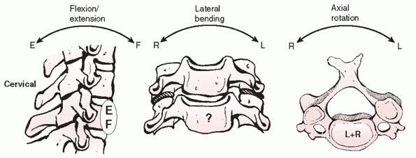 |
|
FIGURE 42-53 The IAR are varied in the cervical spine. With FE (left), the IAR is located somewhere along the anterior aspect of the lower vertebral body. With lateral bending (middle), the IAR is still unknown. With axial rotation (right), the IAR is within a collection of points within the disc space.
|
Knowledge of these figures can be important in assessing spinal
stability after treatment. Flexion-extension motion is greatest at the
C4-C5 and C5-C6 segments, averaging about 20 degrees. Axial rotation
ranges from 2 to 7 degrees at each of the subaxial motion segments; the
majority (45% to 50%) of rotation occurs at the C1-C2 articulation.
Lateral flexion is 10 to 11 degrees per level in the upper segments
(C2-C5). Lateral motion decrements caudally with only 2 degrees
observed at the cervicothoracic junction.
injury to the bony and ligamentous structures alters both load
transmission and the kinematics of the cervical spine. Under
compressive flexion loads, simulated unilateral and bilateral facet
injuries result in anterior displacement of the sagittal IAR and
increased load transmission to the vertebral bodies.64 Anterior translation increases by 33% with sectioning of the intervertebral disc, ALL, and PLL with flexion moments applied.189
The addition of facet resection increases translation to 140%, which
anatomically corresponds to complete occlusion of the spinal canal.189
disruption of bone, ligament, or both. Bone can fail under compression,
tension, or shear loads. In contrast, ligaments can fail only in
tension; this can be likened to a rope that snaps. Perhaps the only
exception to this rule is so-called shear failure of the intervertebral
disc-endplate interaction, although this more accurately reflects
tensile failure of the annular collagen fibers at the bony interface.
upon the vertebral body/disc and tensile loads upon the PLC, which is
comprised of the supraspinous and interspinous ligaments and facet
capsules. Trauma causing hyperflexion can cause compressive failure of
the vertebral body and/or tensile failure of the PLC. Varying
combinations of anterior and posterior failure have been demonstrated
experimentally and clinically.62,200
the ALL and compression across the facet joints. Hyperextension trauma
can lead to tensile failure of the ALL. However, this may not occur
before posterior element compressive fractures, as demonstrated in
cadaveric experiments.109,200 Additional distraction, shear, or rotation appears to be necessary before ALL and intervertebral disc failure.84,109,200
of the anteroinferior vertebral body. Althought to occur most commonly
from a compressive-flexion moment,7 the displacement of the fragment (superior and anterior) supports this proposed injury mechanism (Fig. 42-54).
Teardrop fractures are often associated with wedging or blunting of the
vertebral body. Sometimes there is an associated sagittal split. These
additional fracture features highlight that the exact manner in which
the spinal structures fail is a complex sequence of events that cannot
be reliably deduced from examination of static radiographic studies.
Secondary injury mechanisms from recoil of the head in response to the
primary force vector can lead to circumferential ligamentous and bony
disruption. To further obfuscate matters, the same or similar fracture
patterns have been clinically observed with witnessed axial loading,
flexion, and extension injuries mechanisms.7,66,225
compression fractures of the cervical spine radiographically
demonstrate wedging of the anterior vertebral body without posterior
vertebral body involvement. They can be considered stable if the facet
joints are not subluxed or gapped, there is no vertebral body
translation, and minimal interspinous process gapping (Fig. 42-55). There is often some
degree of kyphosis, which should be carefully measured on a plain
lateral radiograph using the Cobb method. Normally, there is between 2
to 4 degrees of lordosis between adjacent vertebrae. More than 11
degrees of relative kyphosis is strongly suggestive of PLC disruption.
Importantly, absolute kyphosis at the injured segment should be
considered in relation to the measured “normal” lordosis of the
adjacent uninjured segments. If the PLC is disrupted, the injury should
be considered unstable and operative treatment is recommended.
 |
|
FIGURE 42-54 The proposed mechanism of failure of the teardrop fragment is shear. With forced flexion, parallel, but opposite, forces (arrows), are placed on the anterioinferior aspect of the vertebral body.
|
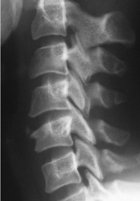 |
|
FIGURE 42-55
Lateral cervical radiograph of a stable compression fracture. There is minimal appreciable kyphosis, no translation, no facet joint gapping, and no evidence of interspinous process widening. |
PLC were based primarily on plain radiographs. In cases in which the
integrity of the PLC is indeterminate using plain radiographs or CT, an
MRI can be obtained. While MRI has been criticized for being overly
sensitive, it can demonstrate discontinuity of the ligamentum flavum,
interspinous and supraspinous ligaments, and reveal soft-tissue edema
between the spinous processes. As patients with simple compression
fractures are usually neurologically intact, determination of the
stability of the injury can have profound consequences.
cervical compression fractures without posterior ligamentous injury can
be treated nonoperatively. For injuries at C3 to C6, a rigid cervical
collar usually suffices. For injuries of C7 or T1, a cervicothoracic
brace may offer better control. Ultimately, if the injury is stable,
the orthosis minimizes motion at the fracture site, which can decrease
pain and facilitate resolution of muscular spasm. Attempts to correct
minor kyphotic deformities are usually fruitless and are in reality
unnecessary. A lateral radiograph should be obtained with patient
sitting up or standing prior to discharge from the hospital, as this
mechanical “litmus” test can sometimes demonstrate instability. The
fracture is usually healed by 3 months, at which time flexion-extension
views under the patient’s own control should be obtained to rule occult
instability, either at the level of the injury or at a distant site,
such as C1-C2, which may have been undetected at the time of initial
presentation.
review of the literature at the time of this writing, there were no
available dedicated series of the results of nonoperative treatment for
simple compression fractures of the subaxial cervical spine.
stabilization via an anterior or posterior approach should be
considered for patients with evidence of posterior ligamentous injury.
Posterior ligamentous injury is suggested by segmental kyphosis greater
than 11 degrees or substantial amounts of vertebral body wedging.
Correlative numbers for the percentage of height loss and PLC injury in
the cervical have not yet been established. MRI evidence for
ligamentous injury should also be considered.
compression fracture with posterior ligamentous injury is essentially a
stage three flexion-compression injury as described by Allen and
Ferguson without the characteristic teardrop-shaped fragment. The
results of surgical treatment of this entity are discussed elsewhere in
this chapter. Reasonably good results have been documented with both
anterior and posterior surgical techniques.
extension vector can be used to realign the fracture. This is best
performed in the awake patient. Although described in more detail for
patients with facet dislocations, a herniated disc may be rule out
based on the MRI as well. If the spinal canal is clear, a
one-
or two-level posterior fusion with instrumentation can be performed. As
compression fractures by definition do not have retropulsed bone
fragments, an anterior corpectomy for canal decompression is usually
not needed. If there is a herniated disc fragment or underlying
degenerative stenosis associated with a neurological deficit, an
anterior corpectomy is elected, followed by cage reconstruction and
stabilization with a plate.
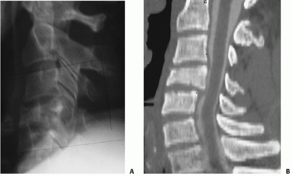 |
|
FIGURE 42-56 Lateral cervical radiograph (A)
of a C4 burst fracture. There is relative kyphosis at the injured segment, in addition to disruption of the posterior vertebral body line. CT (B) confirms the presence of posterior vertebral body fragment retropulsion into the spinal canal. |
fractures are usually high-energy injuries. Radiographic hallmarks are
vertebral body comminution that involves the posterior vertebral body,
usually with retropulsed fragments that result in spinal canal
compromise (Fig. 42-56). Spinal cord injury is
common. Immediate realignment with cranial traction can help clear the
canal to some degree, provided the PLL is intact121
and provide temporary stabilization until surgery. An MRI and CT can be
useful in detecting spinal cord edema and the location of retropulsed
bony fragments.
treatment might be considered in neurologically intact patients with
little vertebral body comminution and only the mildest degree of canal
compromise. There should be minimal kyphotic deformity (neutral or less
than 5 degress of relative kyphosis) and no indication of posterior
ligamentous injury. Because of the potential for vertebral body
collapse, it is the authors’ preference to treat patients in a
halo-vest or rigid CTO. Radiographs should be obtained with the patient
standing or sitting prior to discharge, and rigorous comparisons made
to supine films. High-quality films are crucial. Patients can be
followed weekly for the first month.
contemporary reports of nonoperative treatment of cervical burst
fractures. Classic studies reporting the results of halo vest treatment
of cervical fractures have documented acceptable results with burst
fractures.44,210
neurological deficit, regardless of the integrity of the PLC, should be
surgically stabilized. Retropulsed vertebral body fragments are most
easily accessed through a direct anterior approach. The injured
vertebral body should be corpectomized, and the spinal canal fully
decompressed. Intraoperative traction can help realign the spine if
significant deformity exists (Table 42-4). The
anterior column should be reconstructed with a bone graft/strut. It is
the authors’ preference to insert a rigid titanium mesh cage filled
with salvaged bone in addition to cancellous iliac crest autograft.
Bone should be tightly packed into the cage, which may also enhance the
surface area contact with the endplates. An anterior cervical plate is
then applied to restore anterior stability. If the PLC appears to be
disrupted, it is the authors’ preference to perform a posterior
instrumented fusion, either during the same operation or delayed until
the patient can better tolerate it.
burst fractures. In limited report, Cabanela and Ebersold47
documented good results in eight patients followed for an average of 3
years treated with this approach for so-called bursting teardrop
fractures. In series of mixed injuries, 20 of which were vertical
compression fractures with tetraplegia, Barros Filho et al.18
found that addition of the anterior plate reduced the chance for graft
dislodgement and promoted earlier mobilization of the patients.
|
TABLE 42-4 Pearls and Piftalls: Burst Fractures
|
||||||||
|---|---|---|---|---|---|---|---|---|
|
decompression is not effected, posterior instrumentation and fusion
should be reserved only for patients who are neurologically intact who
have evidence of posterior ligamentous disruption.
unpopularity, there are limited data available of the results of
posterior surgery alone for cervical burst fractures.
lordosis (i.e., normal alignment), no or minimal retropulsion, no
associated neurological deficit, and no posterior ligamentous injury
can be treated nonoperatively. A rigid cervical collar can be used for
fractures of C3 to C6, while a cervicothoracic orthosis (CTO) is
preferred for C7 fractures.
cervical burst fractures are treated surgically. After the spine is
realigned with cervical traction, it is the authors’ preference to
perform an anterior corpectomy of the fractured vertebra. This approach
is used for patients with and without neurological deficit. Anterior
corpectomy enables effective decompression of the spinal canal from
retropulsed bone fragments. With adequate endplate preparation, a
titanium mesh cage filled with salvaged autograft is inserted for
anterior column reconstruction. Traction is then released and an
anterior cervical plate with semiconstrained screws is applied.
dural tears that can lead to chronic CSF leaks or fistulae. In
anticipation of a dural tear, the surgeon may decide to include the
lateral thigh in the operative field for a possible fascia lata graft.
Alternatively, synthetic dural patches can be utilized. Lumbar drains
are usually not necessary, as the cervical dural tube is effectively
decompressed by sitting a patient upright after surgery. Various other
complications related the surgical approach, graft, or instrumentation
can also occur, which are discussed elsewhere in this chapter.
fractures are recognized by their characteristic fracture pattern,
which has been described in detail earlier. They often have a sagittal
split within the posterior vertebral body, leading many authors to
refer to them as burst fractures. Flexion-type tear-drop fractures
typically occur in younger patients with high-energy trauma. Posterior
ligament disruption is suggested by more than 11 degrees of kyphosis or
posterior vertebral body translation (Fig. 42-57). A MRI can be confirmatory. Patients often present with a neurological deficit.
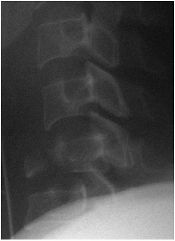 |
|
FIGURE 42-57
Lateral radiograph of a cervical teardrop fracture. This would be considered a stage 5 compressive flexion injury. The classic teardrop fragment can be appreciated, in addition to substantial posterior translation (retrolisthesis) of the upper vertebra on the lower vertebra. The facet joints are also widely gapped. |
definite role for nonoperative treatment of cervical tear-drop
fractures. Minimally displaced fractures with little kyphosis and no
PLC injury are stable. They can be treated in a rigid cervical collar
or CT, depending on the level of injury. Halo treatment can be used to
treat unstable fractures. The apparatus can help realign fractures,
which can effect canal clearance in patients with spinal cord injury.
Importantly, halo treatment for unstable tear-drop fractures results in
inferior radiographic results than anterior surgery, although
neurological and clinical outcome scores appear to be comparable.92
The halo should be kept in place for 3 months, provided acceptable
alignment has been maintained. After the fixator has been removed,
flexion-extension radiograph should be obtained to confirm that
stability has been achieved.
found equivalent neurological and clinical outcomes. Radiographic
outcomes were superior with surgery, as there was a greater average
degree of kyphotic angulation with nonoperative treatment. In an
earlier study, Johnson and Cannon135 reported a low rate of late instability with nonoperative treatment of flexion teardrop fractures.
vertebral body (Table 42-5). This is followed by anterior strut grafting and rigid plating (Fig. 42-58).
In some cases, an unstable tear-drop fracture can occur in a
neurologically intact patient. In these cases, anterior surgery can
include a nondecompressive corpectomy, which entails resection of the
majority of the vertebral body back to, but not through, the posterior
wall. This is best reserved for injuries without retrolisthesis. Some
surgeons prefer to perform a single level discectomy or partial
corpectomy. However, extensive endplate fracture appears to be a risk
factor for failure of anterior alone constructs.136
If the initial injury demonstrated a large amount of translational
deformity (greater than 3 to 3.5 mm) and the facet joints appeared to
be gapped or widened, posterior surgery can be performed to provide
additional stability.
|
TABLE 42-5 Pearls and Pitfalls: Flexion-Type Teardrop Fractures
|
||||||||
|---|---|---|---|---|---|---|---|---|
|
reported superior maintenance of alignment with anterior corpectomy,
fusion, and plate stabilization than halo vest treatment. Others have
also reported good results with anterior surgery for traumatic subaxial
fractures, some of which included flexion teardrop injuries.4,32,204
This should be reserved for patients who are neurologically intact,
have minimal vertebral body height loss, and less than 30% of inferior
endplate involvement. A potential advantage of this approach is that
the fusion can potentially be limited to a single motion segment.
reports of posterior surgery for flexion-type teardrop fractures. Among
series of patients treated for a variety of lower cervical fractures,
posterior stabilization with lateral mass screws has produced
acceptable results.8,86,204
flexion-type teardrop fracture operatively. This opinion is based on a
strict definition of a teardrop fracture, defined as stage III or
greater flexion-compression injuries as described by Allen and Ferguson,7
in which disruption of the posterior ligamentous complex is implied.
Lesser flexion-compression injuries, more appropriately defined as
cervical compression fractures, are discussed earlier.
traction with cranial tongs. Moderate weights (20 to 40 pounds) usually
suffice. Traction can be applied prior to surgery, if a delay is
anticipated, or intraoperatively once the patient is in final position.
Notwithstanding complete spinal cord injuries, close neurological
monitoring is performed by physical exam or intraoperative evoked
potentials. While traction is helpful, translational deformities are
usually not fully reduced with traction alone.
minimally deformity and canal compromise in a patient who is
neurologically intact, anterior corpectomy, fusion, and stabilization
is elected. The fractured vertebral body is removed to effect canal
decompression. A titanium mesh cage filled with salvaged autograft,
supplemented by additional autograft or allograft, is then used to
reconstruct the anterior column. An anterior cervical plate is applied
for stabilization.
authors feel comfortable with this technique if reasonable lordosis has
been restored, excellent screw purchase was achieved, and if the facet
joints are reasonably well-apposed following anterior surgery. Stage
III and IV injuries are usually adequately treated with an anterior
alone construct. With stage V injuries, in which there is marked
translational deformity indicating substantial circumferential
ligamentous injury, additional posterior stabilization and fusion is
elected.
approach, decompression, or stabilization technique, there are few
injury specific complications associated with the operative treatment
of flexion-type teardrop fractures. Perhaps the most vexing is
construct failure following anterior surgery alone. The surgeon must be
confident that the fixation method used will provide adequate stability
until bony fusion occurs. Following posterior-alone surgery, kyphotic
deformity can result from settling of the fractured vertebral body,
particularly with single-level constructs.
wide disagreement concerning the management of facet fractures without
dislocation. The majority of fractures initially present as minimally
displaced fractures (Fig. 42-60). Most can be treated nonoperatively with a rigid cervical collar without substantial late displacement (Table 42-6).
However, in some cases the fracture itself is not the essential lesion.
Occult ligamentous disruption can be present. Thus, MRI has found an
increasingly important role in differentiating so-called stable and
unstable facet fractures and may be an important tool in treatment
decision-making (Fig. 42-61).
fractures are minimally displaced and can be considered mechanically
stable. Such patients can be treated in a rigid cervical collar for a
period of 6 to 12 weeks, monitored by frequent radiographic
examination. It is important
to
recognize, however, that they can be associated with occult unstable
ligamentous injury (demonstrating little if any translational deformity
at initial presentation). Many authors recommend routine MR examination
to rule out significant ligamentous damage. Disruption of the ALL and
intervertebral disc are thought to play in important role in late
displacement, although PLC injury can also occur. Neurological injury
associated with the fracture is rare, and if present is usually limited
to a mild single root radiculopathy that often resolves without formal
decompression. Flexion-extension views should be obtained after the
completion of collar immobilization to ensure stability. While late
displacement is considered to be an indicator of instability by most,
it has been observed that this can auto-stabilize with time. It is
unclear what the long-term consequences of fixed deformity on the
overall clinical outcome.
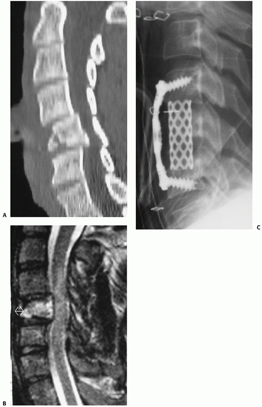 |
|
FIGURE 42-58
Most teardrop fractures are treated with anterior surgery. In this case, an incomplete spinal cord injury was associated with a C5 fracture (A). A sagittal MRI (B) demonstrates enhanced bone edema within the C5 vertebral body, but it is difficult to appreciate the fracture pattern on these images. An anterior C5 corpectomy followed by strut fusion with a cage and anterior plate stabilization was performed (C). |
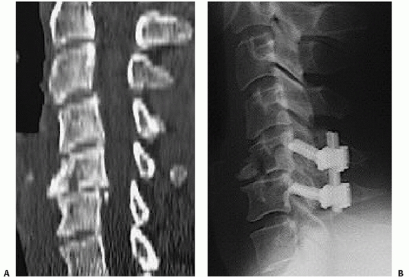 |
|
FIGURE 42-59 Rarely, unstable teardrop fractures in a neurologically intact patient can be treated with posterior surgery alone (A). The theoretical advantage is the ability to fuse only one motion segment (B).
|
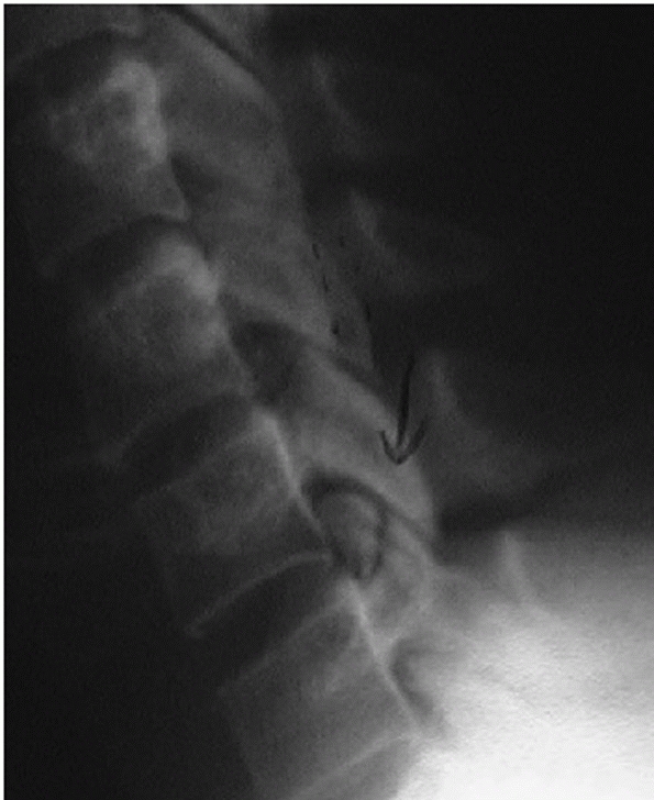 |
|
FIGURE 42-60
Lateral cervical radiograph of a minimally displaced articular process fracture. In the authors’ experience, the majority of these injuries can be treated successfully in a hard cervical collar. Frequent follow-up radiographs should be obtained to detect late instability. |
published retrospective study of unilateral facet injuries, most of
which were facet fractures without dislocation, nonoperative treatment
resulted in longer hospital stays and prolonged return to work than
operative treatment.75 Importantly,
there may have been a study bias in favor of surgery, as nonoperative
treatment could have been more common in patients with more substantial
overall trauma (i.e., polytrauma).
treatment for nearly all facet fractures. Others have focused the
indications by using judicious use of flexion-extension views or MRI. A
validation study of the predictive value of MRI on displacement of
facet fractures has yet to be published.
|
TABLE 42-6 Pearls and Pitfalls: Facet Fractures without Dislocation
|
||||||||
|---|---|---|---|---|---|---|---|---|
|
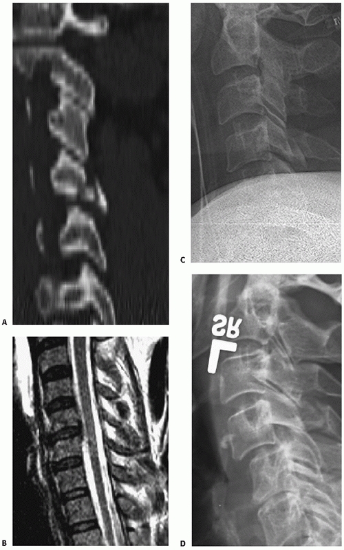 |
|
FIGURE 42-61
Initially nondisplaced, isolated facet fractures can develop subsequent translational instability. This occurrence is probably most influenced by the concomitant soft-tissue injuries. In this case, the initial fracture involved nearly all of the apposed articulating surfaces of the joint (A). MRI demonstrated some minor disruption of the posterior annulus fibrosis (B). While initial radiographs of the patient supine (because of a severe head injury) demonstrated no subluxation (C), radiographs taken at 2 months postinjury demonstrated about 10% to 15% subluxation (D). |
treat facet fractures. Anterior surgery usually consists of a
single-level interbody fusion with a plate (Fig. 42-62).
The advantages of this approach are that the fusion rates are
consistently high, a perceived lower infection rate than posterior
approaches, and the ability to fuse only one motion segment. It is
important to choose the correct level to fuse, which should be based on
the facet joint involved, as opposed to the numerical level of the
articular process fracture.
compared retrospectively analyzed outcomes of nonoperative or posterior
surgery in 32 patients with prospectively gathered outcomes with
anterior disectomy and fusion in 18 patients with so-called
rotationally unstable cervical
injuries,
most of which were unilateral articular process fractures. They found
nonoperative treatment to be unsuccessful in all cases, while patients
with posterior surgery exhibited late kyphosis or residual rotational
deformity in 45% of cases. Although apparently the investigators
preferred treatment method, solid fusion with anatomic reduction was
reported in all patients after anterior surgery.
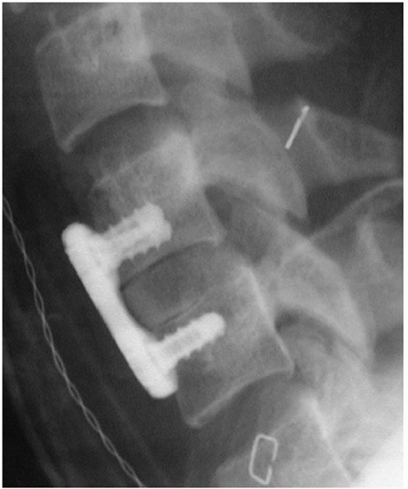 |
|
FIGURE 42-62
If surgery is elected to stabilize a facet fracture, it is the authors’ preference to perform an anterior cervical discectomy and fusion. |
surgery entails stabilization and fusion and can be performed in a
variety of manners. The most mechanically stable constructs are
achieved with the use of bilateral lateral mass screws connected by
rods or plates. However, bilateral screw placement can be precluded
with large articular process fractures, which may necessitate
instrumentation of the next adjacent non-fractured lateral mass. While
these issues are avoided by using interspinous process wiring, the
stability of the construct is inferior and is precluded with lamina
fractures. A combination construct, using an interspinous process wire
and a unilateral lateral mass plate is another option (Fig. 42-63).
found posterior surgery to be inferior to anterior surgery for
rotationally unstable cervical injuries. While it is the current
authors’ preference to perform anterior surgery for these injuries, it
is also their and others’ experience that modern posterior lateral
mass-rod fixation systems can produce comparable radiographical and
clinical results. One potential disadvantage of posterior lateral mass
fixation is the frequent necessity to include an additional motion
segment because of inability to gain adequate screw purchase at the
injured facet level.
fractures with evidence of even mild translational deformities.
Translation of one vertebra on another implies that there is
substantial injury to the intervertebral disc and/or anterior
longitudinal ligament. Because of the risk for late subluxation or
frank facet dislocation, an anterior cervical discectomy, fusion, and
plate stabilization is performed as the preferred treatment. As
deformities are usually mild, reduction is easily achieved
intraoperatively by application of the plate.
translational deformities is more variable. In these cases, MRI is
obtained to determine if the disc or ALL have been disrupted. If there
is strong evidence of disc or ALL injury, operative treatment via
anterior cervical discectomy and fusion is recommended. If injury of
these structures are not detected or the MRI findings are equivocal,
the awake, neurologically intact, and cooperative patient is fitted
with a rigid cervical collar and upright standing films are obtained.
If the alignment is maintained, integrity of the disc and ligaments is
inferred. If upright posture results in subluxation, surgery is
recommended.
are perhaps most common following nonoperative management of isolated
facet fractures. Seemingly benign bony injuries, it is the integrity of
distant ligamentous structures that determines the stability of these
fractures. The authors have personally treated patients with late facet
dislocations that occurred while patients were being immobilized in a
rigid cervical collar. In addition, it is a frequently missed injury
(Levi) that can lead to late neurological deterioration. As outlined
earlier, posterior surgery may lead to greater degrees of postoperative
kyphosis than anterior surgery.157
literature concerning the operative outcomes of unilateral facet
fractures. Because they are considered to be rotational injuries, they
are often reported along with unilateral pedicle fractures and facet
dislocations. In a combined retrospective review of posterior surgery
and prospective analysis of anterior surgery, anterior surgery resulted
in a superior radiographic outcomes.157
facet subluxations and dislocations are not differentiated in the
literature, likely because they represent stages along a continuum from
facet capsule disruption to complete, bilateral locked facets. What is
inconsistent in the continuum, as highlighted by Allen et al.,7
is that unilateral dislocations can occur without catastrophic PLC
disruption, while bilateral facet subluxation (without frank
dislocation) usually occur with PLC disruption.
nonoperative treatment for facet dislocations is minimal. If it is
elected, it should be reserved for unilateral facet dislocations in
patients without any signs of neurological injury or for those who are
too sick to undergo surgery.
cases, cervical orthoses are not usually considered adequate treatment.
The inability of halo-fixation to treat facet dislocations has been
demonstrated by Sears and Fazl,210 with more than 50% of patients exhibiting persistent instability after treatment.
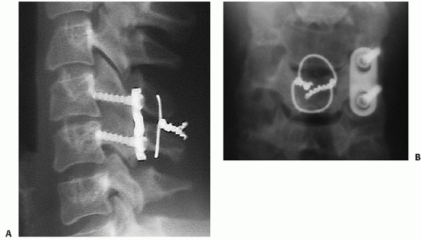 |
|
FIGURE 42-63 A,B.
If posterior surgery is elected, placement of lateral mass screws may not be technically possible on the injured side. In such cases, unilateral plate fixation combined with interspinous wiring can be performed. (Courtesy of John Sledge, MD.) |
of autofusion of the dislocated facet joint or, less frequently the
disc space, is a sign of healing. After a course of about 3 months of
halo immobilization, the device should be removed and the
flexion-extension views should be obtained to confirm stability.
Surgical fusion should be considered if instability is present. In
cases in which stability has been achieved and no spinal cord function
decline has occurred, there is some risk of persistent or late-onset
radiculopathy with unreduced unilateral facet dislocations.
The optimal treatment of unilateral or bilateral facet dislocations
remains unclear. Several different methods can be successful. It is
important to recognize the limitations, advantages, and disadvantages
of each. In several circumstances, one treatment method may be
preferred over another.
MRI has been discussed in previous sections. In summary, closed
reduction appears to be a safe practice in the awake, cooperative
patient that can be serially examined. If the patient does not fulfill
these criteria, particularly in the incomplete spinal cord injured
patient, than prereduction MRI is highly advised to detect a herniated
disc (Table 42-7).
prior to operation, anterior or posterior surgery can be performed.
There is no clear evidence of the superiority of one approach over
another. Conceptually, posterior stabilization more directly addressed
the instability caused by PLC disruption. A postreduction MRI is
usually performed prior to surgery (Fig. 42-64).
Most surgeons believe uncomfortable performing posterior surgery alone
in the presence of a herniated disc after reduction in a neurologically
intact patient. Anterior surgery can be performed to carefully remove
the herniated disc. In the authors’ view, if there the spinal cord is
being indented by a disc herniation following reduction, than anterior
surgery is strongly preferred.
surgery can be an effective means of surgical stabilization of any
facet dislocation. Proponents of this method highlight that posterior
fixation most closely addresses the primary injury site, which is
posterior tension band disruption. Care must be taken, however, if
herniated disc fragments are present. Some consider this to be a
contraindication to posterior surgery, particularly if associated with
a spinal cord injury. Disc herniations can be exaggerated with
posterior compression applied through screws or wires. Posterior
surgery is the most effective approach for open reduction of facet
dislocations. The posterior approach is usually preferred in cases of
late or chronic dislocations.
facet dislocations can be treated with either anterior or posterior
methods, most would consider a large herniated disc following a closed
reduction in the presence of a neurological deficit to be an indication
for anterior decompression. In addition, advocates of prereduction MRI
feel strongly that anterior surgery should be performed first if a
herniated disc fragment is present. Open reduction of a facet
dislocation can be achieved through an anterior approach, although this
is more difficult than with a posterior approach.
with more severe or missed injuries with fixed deformities. It is the
authors’ preference to perform anterior surgery followed by posterior
stabilization for patients with highly unstable bilateral facet
dislocations. If the facets are gapped or kyphosis remains after
anterior surgery, posterior instrumentation is performed to avoid
catastrophic construct failure. Anterior/posterior surgery is rarely
necessary for unilateral dislocations.
|
TABLE 42-7 Pearls and Pitfalls: Facet Dislocations
|
||||||||
|---|---|---|---|---|---|---|---|---|
|
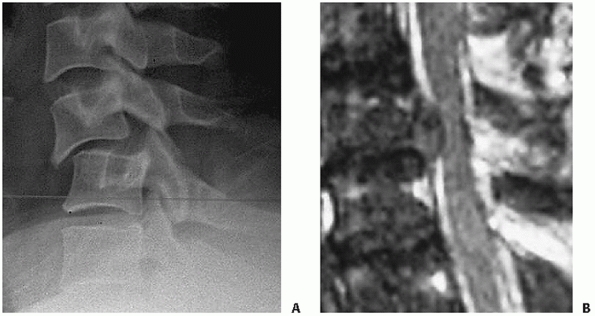 |
|
FIGURE 42-64 Lateral cervical radiograph of a patient with bilateral facet subluxations (A). A postreduction MRI should be performed prior to surgery to detect the presence of a postreduction herniated disc (B). If a herniated disc is present, most surgeons would elect to perform an anterior disectomy and fusion.
|
found anterior fusion to result in better pain relief than posterior
wiring without fusion for facet dislocations. The authors attributed
this to persistent residual motion in the unfused cases. Razack et al.198
performed single level anterior fusion with a titanium locking plate
plate in 22 patients with bilateral facet fracture-dislocations. At an
average follow-up of 32 months, only one case of instrumentation
failure was reported, although all patients eventually had solid fusion
and achieved stability. Vital et al.244
found that 91 bilateral facet dislocations could be successfully
reduced using traction in 43%, manipulation under general anesthesia in
30%, and anterior surgical maneuvers in 27% of cases. Anterior
discectomy and plate fixation was performed in all patients as
definitive treatment. Importantly, there were several patients who had
new-onset neurological deficits after reduction.
results of a series of 24 patients with unilateral facet dislocations.
Although halo treatment was attempted in two patients who had undergone
successful closed reduction, they had recurrent dislocations and
eventually underwent surgery. Thus, all 24 patients underwent posterior
interspinous process wiring. Fusion was successful in 23 (96%) of
cases. In a later study by the same group,212
comparable clinical results were reported with interspinous wiring with
lateral mass plate versus facet wiring with iliac crest for unilateral
facet dislocations. Greater maintenance of kyphotic correction was
observed in the plate group compared to the facet wire/iliac crest
graft group. In a review of their cases, Beyer and Cabenela23 and Beyer et al.24
found that unilateral facet dislocations or fracture-dislocations were
better treated with operative intervention, as nonoperative management
led to an unacceptably high rate of late pain and instability. In a
series of 36 patients, 36% of patients treated with a halo-fixator
demonstrated anatomical alignment compared to 60% in the operative
group.
pitfalls to both approaches. Anterior discectomy and fusion involves
resection of one of the major remaining stabilizing structures—the ALL.
In doing so, one can easily overdistract the disc space while sizing
and placing grafts. This can leave the facet joints gapped posteriorly,
which can obviate posterior column load sharing. Improper fit of the
interbody device can place greater demands on the anterior plate and
screws, which can lead to early hardware failure.
screw placement, injury to the adjacent intact facet joints should be
avoided. While posterior compression can aid in articular apposition,
overcompression can increase intradiscal pressure. This can cause
intraoperative disc herniations that have the potential to cause
additional neurological injury. Intraoperative spinal cord monitoring
is useful in such situations.
reduction using cranial tong or halo traction as early as possible in
patients who are awake, conscious, and able to be serially examined.
This is executed on an emergent or urgent basis as it largely effects
canal decompression. This maneuver is performed regardless of
neurological status or presence of a herniated disc fragment. As there
are no compelling data to suggest that closed reduction in an awake,
examinable patient can lead to a neurological decline, it is the
authors’ experience that performing surgery, either via an anterior or
posterior approach, is more facile if reduction can be achieved prior
to surgery.
surgery for facet dislocations, a postreduction MRI is obtained if
possible. Most would agree that the information yielded from a
post-reduction MRI can influence how and
if
posterior surgery will be executed if a herniated disc fragment is
noted. Although the disc is routinely removed during anterior surgery,
the postreduction MRI can be helpful in identifying the location of the
herniated fragments, which can migrate behind the vertebral body. In
these cases, corpectomy might be elected in lieu of a single level
discectomy to ensure full canal decompression.
earlier. It is the authors’ preference to use a titanium mesh cage
filled with autograft or allograft. A cage that is 7 or 8 mL in height
is usually adequate. After placement of the cage, the head is axial
compressed to maximize endplate engagement with the ends of the cage.
This maneuver also helps to avoid facet gapping.
fixedangle plating, the authors utilize a semirigid plate that allows a
small amount of angular toggle of the screw heads in the plate hole.
Plates with slotted screw holes and axially dynamic plates should be
avoided in the setting traumatic instability.
fluoroscopic images are obtained to assess the integrity of the facet
joint. If the joint surfaces appear to be overly distracted,
particularly common with bilateral facet dislocations and exceedingly
uncommon with unilateral injuries, single level posterior lateral mass
fixation and fusion is then performed as a second stage during the same
anesthetic period.
However, a rigid cervical collar is maintained for 3 months
postoperatively. Regular radiographs are obtained to assess alignment
and bone healing.
Unilateral pedicle fractures are usually considered rotational
injuries. For this reason, their evaluation and treatment is similar to
that for unilateral facet fractures. Bilateral pedicle fractures may be
a sign of higher-energy injury. A high index of suspicion for unstable
ligamentous discontinuity should be maintained.
They are frequently associated with other more significant fractures or
dislocations. Multilevel lamina fractures can suggest a hyperextension
mechanism of injury. Careful inspection of the uniformity of the disc
spaces and the integrity of the ALL on a MRI help detect occult
anterior tension band disruption.
Disruption of the ALL can be associated with vertebral body fracture
that are not extensive, usually avulsion fractures near the anterior
endplate.78 Abnormal widening the disc space is the clue to diagnosis (Fig. 42-52).
They can be associated with posterior fractures or gross PLC
disruption, in which case sagittal and coronal malalignment is present.
Anterior tension band injuries should be considered unstable.
nonoperative treatment is rarely considered a definitive treatment. In
cases in which the patient is too sick to undergo surgery, a halo
device can be applied. Provided the PLC, including facet capsule, are
intact, a flexion moment can reapproximate the vertebral bodies. If
reduction can be maintained, bony ankylosis of the disc space can
occur. Flexion-extension views must be obtained to confirm adequate
stability.
discontinuity of the ALL, intervertebral disc, and possibly the PLL, is
an ideal indication for anterior surgery. An anterior discectomy and
plating with fusion can restore the tension band in its mechanical
sense, just as posterior fixation address PLC disruption with bilateral
facet dislocations. To the authors’ knowledge, there are no dedicated
series of surgical fixation of anterior tension band injuries. As the
proposed mechanism is similar, extension-type cervical teardrop
fractures can be successfully treated with anterior or posterior
surgery.
Patients who present with neck pain and/or neurological deficit after
major or minor trauma should be considered to have a cervical spine
injury until proven otherwise. Degenerative spondylotic changes, such
as vertebral body osteophytes, fixed subluxations, and facet
hypertrophy can make plain films difficult to interpret. Unless a frank
dislocation, translational, or intervertebral widening deformity is
present, plain radiographs may not be helpful in detecting a level of
injury. In these situations, CT and MRI are invaluable in demonstrating
areas of preexisting stenosis, with MRI having obvious advantages in
demonstrating areas of spinal cord contusion, edema, and constriction.
discussion. Two of the more problematic are (a) fractures in patients
with ankylosing spondylitis (AS) and diffisue idiopathic skeletal
hyperostosis (DISH) (b) spinal cord injuries in patients with cervical
spondylosis without ligamentous or bony instability.
The ankylosed spine should be considered as a long bone rather than the
normal spinal column of articulating vertebrae. Bridging osteophytes,
whether marginal as in AS (Fig. 42-65A) or
nonmarginal and flowing as in DISH are the radiographic hallmarks of
these diseases. They effectively fuse the spine into a solid,
continuous piece of bone. As is true for an adult long bone (e.g.,
femur) fracture, if there is a break in one region, it is likely to
have propagated through both the anterior and posterior elements (Fig. 42-65B,C). Thus, fractures in patients with DISH or AS are almost universally unstable and should be treated as such.
fractures is early recognition to avoid catastrophic neurologic
decline. Diagnosis is often missed, resulting in a very high rate of
neurological deficits in previously intact patients.91 Among all cervical fractures, AS has been demonstrated to be a significant risk factor for neurological worsening.57,85
A sudden increase in kyphosis and decrease in horizontal forward gaze
is a common feature with acute fractures in patients with AS. Patients
should be immobilized as soon as the diagnosis is made, admitted to the
hopsital, and placed on strict log-roll precautions until definitive
management has been decided. Patients with AS, with or without
fracture, are predisposed to developing neurological decline from
epidural hematomata.
optimal treatment. There are advocates of nonoperative treatment.
Halo-fixation has been used to successfully maintain alignment and
prevent displacement in patients with and without neurological
deficit111;
however, skin breakdown remains a concern, particular in patients who
will remain recumbent for an extended period of time. Both anterior and
posterior surgery have been advocated as well.32,220 Key principles in management should be kept in mind, regardless of the approach taken.
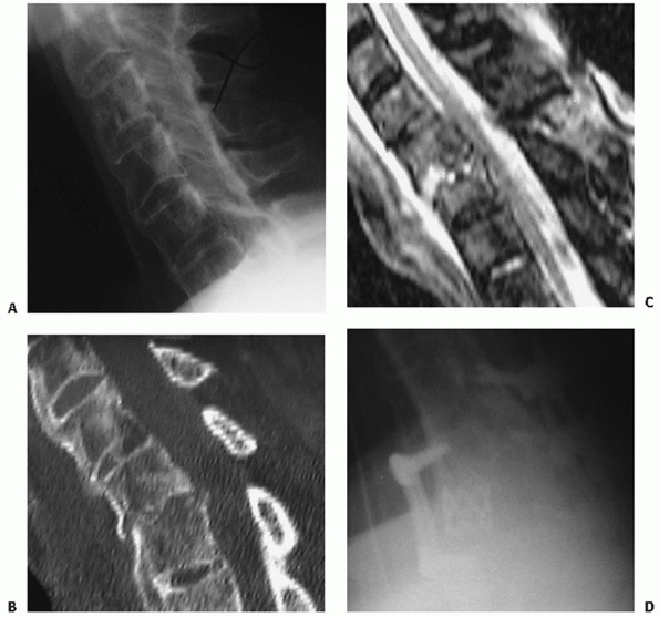 |
|
FIGURE 42-65
Lateral cervical radiograph of a patient with ankylosing spondylitis who was complaining of neck pain after a fall 2 days prior to presentation (A). Note the radiographic hallmarks of marginal bridging osteophytes. Also, note that this single lateral radiograph is inadequate as it does not allow visualization of the cervicothoracic junction. This is best seen on CT (B), which demonstrates an fracture through the ossified disc space. An MRI (C) confirms the presence of posterior soft-tissue injury. Staged posterior and anterior surgery was performed. Note the reverse contouring of the anterior plate (D). |
kyphotic deformity that is often present must be considered. Thus,
inline traction, as is effectively used for most other cases, can lead
to gross displacement and neural impingement. The awake patient should
help guide the position of comfort when applying traction vectors. In
cases of AS, kyphotic deformities usually necessitate a flexion vector.
operative fixation. Both anterior and posterior implants should be
contoured to fix the patients specific anatomy. Unless a concomitant
osteotomy is being planned at the same time, internal fixation of the
fracture should maintain or approximate the preinjury posture of the
neck. This can often necessitate unusual implant contouring (Fig. 42-65D).
Patients often present with complete or incomplete spinal cord injury
without radiographic signs of a frank injury, fracture, or ligamentous
instability. Underlying cervical stenosis is often present, which can
arise from degenerative changes or congenitally narrow canal (Fig. 42-66).
This apparently increases the risk for neural injury with abrupt
movements of the neck that otherwise are not severe enough to cause a
mechanically destabilizing fracture or ligament injury.
Nonoperative treatment can include a period of observation, in
particular for patients with central cord lesions, in which a high
percentage will have nearly complete resolution of their neural
deficits. Long-term treatment is influenced by the presence of
persistent signs or symptoms or myelopathy. Immobilization in a rigid
cervical collar can be useful to avoid the extremes of motion, although
patients usually will not voluntarily move their necks beyond these
limits.
retrospective study, early surgery for patients with incomplete spinal
cord injuries resulted in earlier neurological recovery, with better
motor scores at 1 month and 6 months.53 However, at 2 years, there was no statistically significant difference between the operative and nonoperative groups.53
of neurological recovery over a period of 2 to 3 days. If there are no
signs of neurological return, surgical decompression is performed with
the hopes of improving the rate of recovery. Provided that neurological
examination demonstrates improvements in motor strength, surgery is
postponed. Many patients will have complete motor and sensory recovery
but demonstrate residual signs and symptoms of myelopathy (such as
walking imbalance, diminished finger dextermity). In such cases, a
decompressive procedure is performed electively weeks following the
injury.
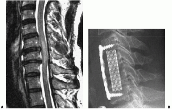 |
|
FIGURE 42-66 MRI of a patient who presented with central cord syndrome (A).
Note the high signal intensity within the spinal cord at the level of the injury. His acute spinal cord injury quickly resolved over a few days following the injury. An anterior decompression was performed on an elective basis 6 weeks after injury for persistent imbalance, diminished upper extremity dexterity, and other myelopathic signs (B). |
reviewed the records of 28 patients. Laminectomy was performed in four
patients and anterior corpectomy in one patient, with no neurological
improvement compared to nondecompressed cases. Neck exploration was
undertaken for vascular damage in four cases, expanding hematoma in two
cases, and airway difficulty in three cases. Long-term complications
were primarily thromboembolisms, pulmonary congestion and urinary tract
infection. Posttraumatic syrinx developed in two patients. Fistulae
occurred in two operatively and two nonoperatively treated patients.
Despite a lack of description of the antibiotic regimen, only one case
of spinal infection (meningitis) was reported. From these limited data,
it seems that care of cervical gunshot wounds should be guided by
similar general principles of other regions.
level is probably not useful in improving static neural deficit, while
it may be beneficial in cases of neurological progression. Laminectomy
can be useful, but should be accompanied by appropriate instrumentation
and fusion.34 Extended antibiotic
prophylaxis is prudent after pharyngeal, hypopharyngeal, or airway
violations. The decision to surgically explore neck wounds should be
dictated by the severity of extraspinal pathology.
upper airway perforation is less clear. Pooled secretions in the
hypopharynx are thought to increase the propensity for infection with
gunshots involving this structure. The decision to explore such wounds
is usually based on the size of the lesion, as small rents can
effectively be treated nonoperatively. To the authors’ knowledge, there
are no controlled studies of the effects of antibiotic prophylaxis
duration after upper airway injuries associated with gunshot wounds to
the spine. Notwithstanding evidence of frank infection or meningitis,
it is prudent to extend prophylaxis for at least 48 to 72 hours.
Delayed exploration for developing neck infections is recommended,
although the role of cervical gunshot wound debridement remains to be
defined.
The vertebral artery within the subaxial spine can be injured after
cervical trauma. The mechanism of injury can be occlusion, laceration,
or distractive avulsion. Vertebral artery injury can occur with
fractures of the transverse processes, through which the vertebral
artery passes. Magnetic resonance arteriograms are an effective means
of noninvasive diagnosis of vertebral artery occlusion or narrowing
following cervical trauma. Formal dyeinjection arteriography is another
option.
In most cases, no specific treatment is necessary. However, the
detection of the injury can have important influences on overall
treatment decision-making. The surgeon must consider the consequences
of
surgical techniques that can incur some risk to the vertebral artery,
such as lateral mass screw placement or C1-C2 transarticular screw
insertion. It may be prudent to avoid such procedures on the unaffected
side, which can potentially lead to bilateral vertebral artery
occlusion.
leading to cerebellar infarction. This has been reported in patients
with severe dislocations of the subaxial cervical spine.172 This may prompt recanalizing pharmacological or angiographic therapies.
By themselves, lower spinous process fractures are usually benign
injuries. The so-called clayshoveler’s fracture is thought to occur
from powerful contraction of the muscles that insert onto the spinous
process. However, spinous process fractures can be present with lamina
fractures, facet dislocations, and various other more significant
injuries. An early report described spinous process fractures that are
associated with bilateral lamina fractures as a sentinel sign to
possible neurological deterioration.169 It is thought that the floating posterior arch can be pushed forward into the spinal canal.
Vascular injuries are frequently associated with cervical spine
fractures. The close proximity of the internal carotid and vertebral
arteries places these structures at particular risk. In one report,
Chen et al.52 documented two cases
of internal carotid artery dissection after isolated type III occipital
condylar fracture. Based on their findings, the authors recommended
cerebral angiography in patients with traumatic occipital condylar
fractures. Muratsu et al.178 reported a case of cerebellar infarction following vertebral artery occlusion following a Jefferson fracture.
various aspects of treatment of lower cervical spine injuries. The
benefits of early decompression of spinal cord injuries have also been,
and will continue to be, a focus of heated discussion. Debate will no
doubt continue concerning the safety of awake, immediate reductions for
patients with facet dislocations and the role of a prereduction MRI.
Likewise, controversy about the optimal surgical treatment of these
injuries will continue, as many still believe that anterior surgery
alone is doomed to fail.
treatment of facet fractures is likely to remain controversial. While
some feel strongly that nearly all can be treated by nonoperative
means, regardless of the development of small amounts of displacement,
others remain firm that the injury should not be underestimated and
requires surgical stabilization in most cases. This controversy
represents, in the authors’ opinion, a glaring example of the lack of
understanding of the natural history of such a seemingly benign injury.
It underscores the need to look further into the injury patterns, and
perhaps rely more heavily on MRI to stratify concomitant ligamentous
injuries.
they be minimally invasive or motion-sparing, are on the horizon, their
utility and role will depend on a better understanding of spinal
injuries. In anticipation of these times, future efforts should be
focused on developing a usable, reproducible, and reliable injury
description system, on which a prognostic and treatment-influencing
classification system can be built.
S, Dacher JN, Lechevallier J. Posterior arch bifocal fracture of the
atlas vertebra: a variant of Jefferson fracture. J Pediatr Orthop B
2001;10:201-204.
VI. Neck injuries: I. Occipitoatlantal dislocation: a pathologic study
of twelve traffic fatalities. J Forensic Sci 1992;37:556-564.
M, Zuber K, Marchesi D. Treatment of cervical spine injuries with
anterior plating. Indications, techniques, and results. Spine
1991;16:S38-S45.
I, Manik KS, Sian PS, et al. Occipital condylar fractures. Review of
the literature and case report. J Bone Joint Surg Br 2006;88:665-669.
B, Ferguson R, Lehmann T, et al. A mechanistic classification of
closed, indirect fractures and dislocations of the lower cervical
spine. Spine 1982;7:1982.
HS, Coppes MS. Posterior cervical fixation for fracture and
degenerative disc disease. Clin Orthop Relat Res 1997;335:101-111.
AJ, Towns GM, Chiverton N. Traumatic occipitocervical disruption: a new
technique for stabilisation. Case report and literature review. J Bone
Joint Surg Br 2006; 88:1464-1468.
PA, Moore TA, Davis KW, et al. Cervical spine injury severity score.
Assessment of reliability. J Bone Joint Surg Am 2007;89:1057-1065.
S, Rodrigues M, Olerud C. Odontoid fractures: high complication rate
associated with anterior screw fixation in the elderly. Eur Spine J
2000;9:56-59.
JL, Dekutoski MB. Management of unilateral facet dislocations: a review
of the literature. Orthopedics 1997;20:917-926.
JA, Finlay DB, Allen MJ, et al. A review of cervical-spine radiographs
in casualty patients. Br J Radiol 1987;60:1059-1061.
T, Takatsu A, Shigeta A. Unusual mechanism of lethal cervical spinal
cord injury in a case of atlanto-axial diastasis. Int J Legal Med
1993;106:41-43.
V, Eismont FJ. Efficacy of five cervical orthoses in restricting
cervical motion: a comparison study. Spine 1997;22:1193-1198.
JM, Tutt LK, Kaye JJ, et al. Occipital condyle fractures: clinical
presentation and imaging findings in 76 patients. Emerg Radiol
2005;11:342-347.
Filho TE, Oliveira RP, Grave JM, et al. Corpectomy and anterior plating
in cervical spine fractures with tetraplegia. Rev Paul Med
1993;111:375-377.
TC, Tannoury T, Crowl AC, et al. A cadaveric study comparing standard
fluoroscopy with fluoroscopy-based computer navigation for screw
fixation of the odontoid. J Surg Orthop Adv 2005;14:175-180.
DP, Stanfield M, Martin HD, et al. Transoral vertebral augmentation
with polymethylmethacrylate in the treatment of a patient with a dens
fracture nonunion and subarticular vertebral body fracture of C2.
Skeletal Radiol 2007;36:453-458.
C, Mirza SK, West GA, et al. Diagnosis and treatment of craniocervical
dislocation in a series of 17 consecutive survivors during an 8-year
period. J Neurosurg Spine 2006;4:429-440.
CA, Cabanela ME. Unilateral facet dislocations and
fracture-dislocations of the cervical spine: a review. Orthopedics
1992;15:311-315.
CA, Cabanela ME, Berquist TH. Unilateral facet dislocations and
fracture-dislocations of the cervical spine. J Bone Joint Surg Br
1991;73:977-981.
A, Sawhney G, Kaushal R, et al. Management of odontoid fractures with
anterior screw fixation. J Surg Orthop Adv 2006;15:38-42.
HG, Ford S, Bezmalinovic Z, et al. The effect of axial traction during
orotracheal intubation of the trauma victim with an unstable cervical
spine. Ann Emerg Med 1989; 17:25-29.
MF, Lee HJ. Frequency and significance of fractures of the upper
cervical spine detected by CT in patients with severe neck trauma. AJR
Am J Roentgenol 1995; 165:1201-1204.
WH, Iserson KV, Bjelland JC. Efficacy of the posttraumatic cross table
lateral view of the cervical spine. J Emerg Med 1985;2:243-249.
M, Richter M, Kiesewetter B, et al. [Operative versus non operative
treatment of odontoid non unions. How dangerous is it not to stabilize
a non union of the dens?]. Chirurg 1999;70:1225-1238.
AI, Neeman Z, Slasky BS, et al. Fracture of the occipital condyles and
associated craniocervical ligament injury: incidence, CT imaging and
implications. Clin Radiol 1997;52:198-202.
KD, Catalano JB, Cotler JM, et al. The pullout strength of titanium
alloy MRI-compatible and stainless steel MRI-incompatible Gardner-Wells
tongs. Spine 1993;18: 1895-1896.
J, Gaudernak T. Anterior plate stabilization for fracture-dislocations
of the lower cervical spine. J Trauma 1980;20:203-205.
CM, Vaccaro AR, Fehlings M, et al. Measurement techniques for upper
cervical spine injuries: consensus statement of the Spine Trauma Study
Group. Spine 2007; 32:593-600.
RV, de Souza Palma AM, Abgussen CM, et al. Traumatic vertical
atlantoaxial instability: the risk associated with skull traction. Case
report and literature review. Eur Spine J 2000;9:430-433.
MJ, Byrne TP, Abrams RA, et al. Halo Skeletal Fixation: techniques of
Application and Prevention of Complications. J Am Acad Orthop Surg
1996;4:44-53.
JL, Colli BO, Carlotti CG, Jr., et al. Surgical management of axis’
traumatic spondylolisthesis (hangman’s fracture). Arq Neuropsiquiatr
2004;62:821-826.
H, Karakas A, Hanci M, et al. Finite element model of the Jefferson
fracture: comparison with a cadaver model. Eur Spine J 2001;10:257-263.
R, Henn JS, Dickman CA. Pars screw fixation of a hangman’s fracture:
technical case report. Neurosurgery 2005;56:E204; discussion E.
DS, Anderson PA, Newell DW, et al. Comparison of anterior and posterior
approches in cervical spinal cord injuries. J Spinal Disord Tech
2003;16:229-235.
RD, Cheung KC. Halo vest versus spinal fusion for cervical injury:
evidence from an outcome study. J Neurosurg 1989;70:884-892.
ME, Ebersold MJ. Anterior plate stabilization for bursting teardrop
fractures of the cervical spine. Spine 1988;13:888-891.
M, Kattner KA, Stroink A, et al. Posterior C1-C2 transarticular screw
fixation in the treatment of displaced type II odontoid fractures in
the geriatric population: review of seven cases. Surg Neurol
1999;51:596-600; discussion 601.
C, Costagliola C, Shamsaldin M, et al. Occipital condyle fractures: a
hidden nosologic entity. An experience with 10 cases. Acta Neurochir
(Wien) 2004;146: 779-784.
E, Rocchi G, Orlando ER, et al. Occipital condyle fractures: report of
five cases and literature review. Eur Spine J 2005;14:487-492.
JY, Soares G, Lambiase R, et al. A previously unrecognized connection
between occipital condyle fractures and internal carotid artery
injuries (carotid and condyles). Emerg Radiol 2006;12:192-195.
TY, Dickman CA, Eleraky M, et al. The role of decompression for acute
incomplete cervical spinal cord injury in cervical spondylosis. Spine
1998;23:2398-2403.
A, Moorman DW, Timberlake GA. An evaluation of the effects of semirigid
cervical collars in patients with severe closed head injury. Am Surg
1998;64: 604-606.
S, Kamian K, Depreitere B, et al. Occipital condyle fracture with
associated hypoglossal nerve injury. Can J Neurol Sci 2006;33:322-324.
JR, Scheidel E, Bigsby EF. A comparison of methods of cervical
immobilization used in patient extrication and transport. J Trauma
1985;25:649-653.
NR, Bednar DA. Identifiable risk factors for secondary neurologic
deterioration in the cervical spine-injured patient. Spine
1995;20:2293-2297.
PR, Maravilla KR, Sklar FH, et al. Halo immobilization of cervical
spine fractures. Indications and results. J Neurosurg 1979;50:603-610.
D, Wilson JA, Kelly DL Jr. Treatment of traumatic spondylolisthesis of
the axis with nonrigid immobilization: a review of 64 cases. J
Neurosurg 1996;85:550-554.
JM, Herbison GJ, Nasuti JF, et al. Closed reduction of traumatic
cervical spine dislocation using traction weights up to 140 punds.
Spine 1993;18:386-390.
JF, Yoganandan N, Pintar FA, et al. Biomechanics of cervical spine
facetectomy and fixation techniques. Spine 1988;13:808-812.
RH, Brown RR, Goldberg AL. A new classification for cervical vertebral
injuries: influence of CT. Skeletal Radiol 2000;29:125-132.
HG, Tolchin S. Combination Jefferson fracture of C1 and type II
odontoid fracture requiring surgery: report of two cases. Neurosurgery
1989;25:293-297.
G, Horodyski M, Heffernan TP, et al. Spine-board transfer techniques
and the unstable cervical spine. Spine 2004;29:E134-E144.
JR, Glassman SD, Raque GH, et al. The influence of spinal canal
narrowing and timing of decompression on neurologic recovery after
spinal cord contusion in a rat model. Spine 1999;24:1623-1633.
N, Chamberlain RH, Perez-Garza LE, et al. Hangman’s fracture: a
biomechanical comparison of stabilization techniques. Spine
2007;32:182-187.
MF, Fisher CG, Aarabi B, et al. Clinical outcomes of 90 isolated
unilateral facet fractures, subluxations, and dislocations treated
surgically and nonoperatively. Spine 2007;32:3007-3013.
MF, Fisher CG, Fehlings MG, et al. The surgical approach to subaxial
cervical spine injuries: an evidence-based algorithm based on the SLIC
classification system. Spine 2007;32:2620-2629.
FJ, Arena MJ, Green BA. Extrusion of an intervertebral disc associated
with traumatic subluxation or dislocation of cervical facets. Case
report. J Bone Joint Surg Am 1991;73:1555-1560.
H, Bohm H. Anderson type II fracture of the odontoid process: results
of anterior screw fixation. J Spinal Disord 2000;13:527-530; discussion
531.
E, Saillant G, Ismail M, et al. Fracture of the occipital condyle: case
report and review of the literature. Eur Spine J 1995;4:191-193.
H, Kalen R. A consecutive series of 64 halo-vest-treated cervical spine
injuries. Arch Orthop Trauma Surg 1986;105:243-246.
HF, Cosette JW, Robertson HG, et al. The effects of torsion in the
production of disc regeneration. J Bone Joint Surg Am 1970;52A:468.
J, Vaccaro A, Balderston R, et al. The changing nature of admission to
a spinal cord injury center: violence on the rise. J Spinal Disord
1998;11:400-403.
MF, Cooper PR, Errico TJ. Posterior plates in the management of
cervical instability: long-term results in 44 patients. J Neurosurg
1994;81:341-349.
I, Gonzalez LF, Dickman CA. Atlantooccipital transarticular screw
fixation for the treatment of traumatic occipitoatlantal dislocation.
Technical note. J Neurosurg Spine 2005;2:381-385.
Nielsen C, Annertz M, Persson L, et al. Fusion or stabilization alone
for acute distractive flexion injuries in the mid to lower cervical
spine. Eur Spine J 1997;6: 197-202.
CG, Dvorak MF, Leith J, et al. Comparison of outcomes for usntable
lower cervical flexion teardrop fractures managed with halo thoracic
vest versus anterior corpectomy and plating. Spine 2002;27:160-166.
CG, Sun JC, Dvorak M. Recognition and management of atlanto-occipital
dislocation: improving survival from an often fatal condition. Can J
Surg 2001;44:412-420.
SV, Bower JF, Awad EA, et al. Cervical orthoses effect on cervical
motion: roetngeniographic and goniometric method of study. Arch Phys
Med Rehabilit 1977; 58:109-115.
BJ, Behensky H. Bilateral occipital condyle fractures leading to
retropharyngeal haematoma and acute respiratory distress. Injury
2005;36:207-212.
D, Flanders A, Thomas C, et al. Vertebral artery injury after acute
cervical spine trauma: rate of occurence as dected by MR angiography
and assessment of clinical consequences. AJR Am J Roentgenol
1995;164:443-447.
S, Bouillot P, Palombi O, et al. Traumatic atlantoaxial rotatory
dislocation with odontoid fracture: case report and review. Spine
2001;26:830-834.
SR, Botte MJ, Waters RL, et al. Complications in the use of the halo
fixation device. J Bone Joint Surg Am 1986;68:320-325.
TA, Eismont FJ, Roberti LJ. Anterior decompression, structural bone
grafting, and Caspar plate stabilization for unstable cervical spine
fractures and/or dislocations. Spine 1992;17:S431-S435.
VL, Hollermann JJ, Ney AL, et al. Incidence and diagnosis of C7-T1
fractures and subluxations in multiple-trauma patients: evaluation of
the advanced trauma life support guidelines. Surgery 1989;106:708-709.
J, van Loon J, Van Calenbergh F, et al. Long-term results after
anterior cervical fusion and osteosynthetic stabilization for fractures
and/or dislocations of the cervical spine. J Spinal Disord
1995;8:499-498.
AL, Rothfus WE, Deeb ZL, et al. The impact of magnetic resonance on the
diagnostic evaluation of acute cervicothoracic spinal trauma. Skeletal
Radiol 1988;17: 89-95.
W, Mueller C, Panacek E, et al. Distribution and patterns of blunt
traumatic cervical spine injury. Ann Emerg Med 2001;38:17-21.
SJ, Woodring JH, Young AB. Occipital condyle fracture associated with
cervical spine injury. Surg Neurol 1982;17:350-352.
J, Nanda A. Occipito-atlantal dislocation: an uncommon case of cervical
spine injury. J La State Med Soc 2006;158:297-298, 300-201.
S, Vlok GJ, Fisher-Jeffes N, et al. Traumatic dislocation of the
atlanto-occipital joint. J Bone Joint Surg Br 2003;85:875-878.
B, Van Peteghem PK. Fractures of the spine in ankylosing spondylitis.
Diagnosis, treatment, and complications. Spine 1989;14:803-807.
GA, Mirza SK, Chapman JR, et al. Risk of early closed reduction in
cervical spine subluxation injuries. J Neurosurg 1999;90:13-18.
JN, Shafi B, Hilibrand AS, et al. Proposal of a modified,
treatment-oriented classification of odontoid fractures. Spine J
2005;5:123-129.
G, Jaggers C, Lee M, et al. A comparative study of fixation techniques
for type II fractures of the odontoid process. Spine 1993;18:2383-2387.
KA, Dickman CA, Marciano FF, et al. Acute axis fractures. Analysis of
management and outcome in 340 consecutive cases. Spine
1997;22:1843-1852.
R, Boto GR, Perez-Zamarron A, et al. Retropharyngeal pseudomeningocele
formation as a traumatic atlanto-occipital dislocation complication:
case report and review. Eur Spine J 2007.
TR, Yeung AW, Caruso SA, et al. Occipital screw pullout strength. A
biomechanical investigation of occipital morphology. 1999;24:5-9.
JA, Deliganis AV, Baxter AB, et al. Radiologic and clinical spectrum of
occipital condyle fractures: retrospective review of 107 consecutive
fractures in 95 patients. AJR Am J Roentgenol 2002;178:1261-1268.
J, MacIntosh PK, Sherbon KJ. Fracture of the occipital condyle. A case
report and review of the literature. J Bone Joint Surg Am
1981;63:1170-1171.
RM, Budorick T, Hoyt J, et al. Biomechanics of indirect reduction of
bone retropulsed into the spinal canal in vertebral fracture. Spine
1993;18:692-699.
R, Saterbak A, Rapp T, et al. Nonoperative management of dens fracture
nonunion in elderly patients without myelopathy. Spine
2000;25:1339-1343.
RF, Hunt CD, Krieger AJ, et al. Acute stabilization of the cervical
spine by halo/vest application facilitates evaluation and treatment of
multiple trauma patients. J Trauma 1992;33:445-451.
C, Richter HP, Rath SA. Atlantoaxial screw fixation for the treatment
of isolated and combined unstable Jefferson fractures – experiences
with 8 patients. Acta Neurochir (Wien) 2002;144:1187-1192.
JG, Viroslav S, Hudson T. Jefferson fractures: the role of
magnification artifact in assessing transverse ligament integrity. J
Spinal Disord 1993;6:392-396.
CH, Ball PA, Sargent SK, et al. Sensitivity of prevertebral soft tissue
measurement of C3 for detection of cervical spine fractures and
dislocations. Am J Emerg Med 1998; 16:346-349.
VK, Mittal P, Banerji D, et al. Posterior occipitoaxial fusion for
atlantoaxial dislocation associated with occipitalized atlas. J
Neurosurg 1996;84:559-564.
A, Tatsui C, Farhat H, et al. Vertically unstable type III odontoid
fractures: case report. Neurosurgery 2006;58:E797; discussion.
B, Magerl F. Primary posterior fusion C1/2 in odontoid fractures:
indications, technique, and results of transarticular screw fixation. J
Spinal Disord 1992;5:464-475.
B, Magerl F, Ward JC. Overdistraction: a hazard of skull traction in
the management of acute injuries of the cervical spine. Arch Orthop
Trauma Surg 1991; 110:242-245.
JL, Cannon D. Nonoperative treatment of the acute tear-drop fracture of
the cervical spine. Clin Orthop 1982;168:108-112.
M, Dvorak MF, Fisher C. The radiographic failure of single-segment
anterior cervical plate fixation in traumatic cervical
flexion/distraction injuries. Spine J 2002; 5S:57S.
RM, Hart DL, Owen JR, et al. The Yale cervical orthosis: an evaluation
of its effectiveness in restricting cervical motion in normal subjects
and a comparison with other cervical orthoses. Phys Ther
1978;58:865-871.
RM, Hart DL, Simmons EF, et al. Cervical orthoses: a study comparing
their effectiveness in restricting cervical motion in normal subjects.
J Bone Joint Surg Am 1977;59A:332-339.
MS. A comparative study of the foramen transversarium of the sixth and
seventh vertebra. Surg Radiol Anat 1990;12:167-172.
RW, Benedetti PF, Drake CM, et al. Acute cervical spine injuries:
prospective MR imaging assessment at a level 1 trauma center. Radiology
1999;213:205-212.
V, Kelly G, Richards SD, et al. Isolated unilateral hypoglossal nerve
palsy after minor head trauma. Clin Neurol Neurosurg 2002;105:42-47.
MP, Kiuru MJ, Koskinen SK, et al. Factors associated with nonunion in
conservatively-treated type-II fractures of the odontoid process. J
Bone Joint Surg Br 2004;86(8):1146-1151.
E, Ambrozaitis KV, Spakauskas B, et al. The treatment of odontoid
fractures with a significant displacement. Medicina (Kaunas)
2005;41:23-29.
BK, Fisher CG, Boyd MC, et al. A prospective randomized controlled
trial of anterior compared with posterior stabilization for unilateral
facet injuries of the cervical spine. J Neurosurg Spine 2007;7:1-12.
SB, Anderson PA, Oza A, et al. Biomechanical comparison of four C1 to
C2 rigid fixative techniques: anterior transarticular, posterior
transarticular, C1 to C2 pedicle, and C1 to C2 intralaminar screws.
Neurosurgery 2006;58:516-521; discussion 521.
C, Woodring JH. Unstable Jefferson variant atlas fractures: an
unrecognized cervical injury. AJNR Am J Neuroradiol 1991;12:1105-1110.
TT, Green BA, Petrin DR. Treatment of stable burst fracture of the
atlas (Jefferson fracture) with rigid cervical collar. Spine
1998;23:1963-1967.
JA, Haynes RJ, Koeneman EJ, et al. A biomechanical comparison of
Gardner-Wells tongs and halo device used for cervical spine traction.
Spine 1994;19: 2403-2406.
LM, Docherty M, Ruoff BE, et al. Flexion-extension views in the
evaluation of cervical-spine injuries. Ann Emerg Med 1991;20:117-121.
B, al Refai M, Sharma S, et al. Fuctional recovery after near complete
traumatic deficit of the cervical cord lasting more than 24h. Br J
Neurosurg 1992;6: 375-380.
SC, Vaccaro AR, Balderston RA, et al. Immediate quadriparesis after
manipulation for bilateral cervical facet subluxation. A case report. J
Bone Joint Surg Am 1997; 79A:587-590.
RL, Schwartz ML, Mirich D, et al. Diagnosis of cervical spine injury in
motor vehicle crash victims: how many x-rays are enough? J Trauma
1990;30:392-397.
P, Monk J, Wilson-MacDonald J, et al. Instability due to unrecognised
fracture-subluxations after apparently isolated injuries of the
cervical spine. J Bone Joint Surg Br 2001;83:486-490.
JF, Perez-Espejo MA, Masegosa J, et al. Bilateral brain abscesses
complicating the use of Crutchfield tongs. Childs Nerv Syst
1986;2:208-210.
AD, Mukherjee DP, Kruse RN, et al. Anterior screw fixation of type II
odontoid fractures. A biomechanical study. Spine 1995;20:1855-1859;
discussion 1859-1860.
S, Okamura K, Wantanabe M, et al. Cerebellar stroke due to vertebral
artery occlusion after cervical spine trauma. Two case reports. Spine
1994;19:83-88.
C, Katsume M, Yamazaki T, et al. Unusual occipital condyle fracture
with multiple nerve palsies and Wallenberg syndrome. Clin Neurol
Neurosurg 2000;102: 255-258.
J, Harth A, Van Trimpont I, et al. Treatment of unstable fractures,
dislocations and fracture-dislocations of the cervical spine with
Senegas plate fixation. Acta Orthop Belg 1994;60:30-35.
JL, Montgomery ML. Radiographic evaluation of cervical spine trauma.
Procedures to avoid catastrophe. Postgrad Med 1994;95:173-174, 177-179,
182184.
DS, Wallace DH, Woolhouse FM. The use of fiberoptic bronchoscope to
facilitate endotracheal intubation following head and neck trauma. J
Trauma 1975;15: 638-640.
H, Doita M, Yanagi T, et al. Cerebellar infarction resulting from
vertebral artery occlusion associated with a Jefferson fracture. J
Spinal Disord Tech 2005;18: 293-296.
SM, Louis RP. Posterior internal fixation with screw plates in
traumatic lesions of the cervical spine. Spine 1991;16:S64-S71.
S, Watts C, Loos L, et al. Use of traction in cervical spine fractures
during interhospital tranfer by aircraft. J Spinal Disord 1990;3:67-76.
WP, Fehlings MG, Cuddy Bx, et al. Surgical treatment of acute spinal
cord injury pilot study#2: evaluation of protocol for decompressive
surgery within 8 hours after injury. Neurosurg Focus 1999;6:3.
P, Bose WJ, Hurely DP, et al. Superficial temporal artery laceration. A
complication of skull tong traction. Orthop Rev 1992;21:761, 764-765.
BE, Vaccaro AR, Rosen JE, et al. Occurrence of infection in anterior
cervical fusion for spinal cord injury after tracheostomy. Spine
1995;20:2449-2453.
RC, Seigal S, Merola AA, et al. Computed tomographic evaluation of the
normal adult odontoid. Implications for internal fixation. Spine
1995;20:264-270.
I, Abumi K, Sell LC, et al. Biomechanical evaluation of five different
occipitoatlanto-axial fixation techniques. Spine 1999;24:2377-2382.
PJ, Currier BL, Neale PG, et al. Biomechanical evaluation of posterior
screw fixation in cadaveric cervical spines. Clin Orthop 2003;411:13-24.
M, Delavelle J. Bilateral occipital condylar fracture. Case report
about successful treatment with SOMI brace. J Clin Neurosci
2004;11:211-214.
S, Bonetti MG, Ghirlanda S, et al. Technical note: CT scout views of
the cervical spine in severely head-injured patients. Skeletal Radiol
1996;25:247-249.
V, Petitjean ME, Wiart L, et al. Pharmacological therapy of spinal cord
injury model in the rat. Surg Neurol 2000;10:71-76.
GJ, Welch WC. Longitudinal atlantoaxial dislocation with type III
odontoid fracture. Case report and review of the literature. J
Neurosurg 1996;84:666-670.
S, Vidyadhara S, Shetty AP. Intra-operative Iso-C3D navigation for
pedicle screw instrumentation of hangman’s fracture: a case report. J
Orthop Surg (Hong Kong) 2007;15:73-77.
MJ, Wolf A, Levi L, et al. The use of anterior Caspar plate fixation in
acute cervical spine injury. Surg Neurol 1991;36:181-189.
N, Green B, Levi AD. The management of traumatic cervical bilateral
facet fracture-dislocations with unicortical anterior plates. J Spinal
Disord 2000;13:374-381.
M, Tyberghien A, Matge G. Asymptomatic vertebral artery injury after
acute cervical spine trauma. Acta Neurochir 2001;143:939-945.
CA, Bertozzi JC, Martinez CR, et al. Reassessment of the craniocervical
junction: normal values on CT. AJNR Am J Neuroradiol 2007;28:1819-1823.
M, Melcher R, Harms J. Transoral reduction and osteosynthesis C1 as a
functionpreserving option in the treatment of unstable Jefferson
fractures. Spine 2004;29: 823-827.
SA, Vaccaro AR, Levine MJ, et al. Bivector traction for unstable
cervical spine fractures: a description of its application and
preliminary results. J Spinal Disord 1997; 10:436-440.
A, Green R, White J. Magnetic resonance imaging of the cervical
ligaments in the absence of trauma. Spine 2003;28:1686-1691.
W, Fazl M. Prediction of stability of cervical spine fracture managed
in the halo vest and indications for surgical intervention. J Neurosurg
1990;72:426-432.
EA, Bayley JC. Functional outcome of surgically and conservatively
managed dens fractures. Spine 1998;23:1837-1845; discussion 1845-1846.
CE, Fallon WF. Sevoflurane mask anesthesia for urgent tracheostomy in
an uncooperative trauma patient with a difficult airway. Can J Anaesth
2000;47:242-245.
KF, Decker S, Sell KW. Bursting atlantal fracture associated with
rupture of the transverse ligament. J Bone Joint Surg Am
1970;52:543-549.
BR, Morone MA, Haid RW, Jr., et al. Management of acute odontoid
fractures with single-screw anterior fixation. Neurosurgery
1999;45:812-819; discussion 819-820.
TM, Lauerman WC, Blanc RO, et al. Cervical alignment in the immobilized
football player: radiographic analysis before and after helmet removal.
Am J Sports Med 1997;25:226-230.
DA, Traynelis VC. Management of cervical spinal fractures in ankylosing
spondylitis with posterior fixation. Spine 2000;25:2035-2039.
PA, Young JW, Mirvis S, et al. The value of retropharyngeal soft tissue
measurements in trauma of the adult cervical spine. Cervical spin soft
tissue measurements. Skeletal Radiol 1987;16:98-104.
EC, Paul JP, Evans JH, et al. Experimental investigation of failure
load and fracture patterns of C2 (axis). J Biomech 2001;34:1005-1010.
JS, Pavlov H, O’Neill MJ, et al. The axial load teardrop fracture. A
biomechanical, clinical and roentgenographic analysis. Am J Sports Med
1991;19:355-364.
JS, Sennett B, Vegso JJ, et al. Axial loading injuries to the middle
cervical spine segment. An analysis and classification of twenty-five
cases. Am J Sports Med 1991; 19:6-20.
GF, Papadopoulos SM, Sonntag VK. Caspar plate fixation for the
treatment of complex hangman’s fractures. Neurosurgery 1992;30:761-764;
discussion 764-765.
E, Arrazola M, Arrazola M, Jr., et al. Delayed glossopharyngeal and
vagus nerve paralysis following occipital condyle fracture. Case
report. J Neurosurg 1996;84: 522-525.
AR, An HS, Betz RR, et al. The management of acute spinal trauma:
prehospital and in-hospital emergency care. Instru Course Lect
1997;46:113-125.
AR, Daugherty RJ, Sheehan TP, et al. Neurologic outcome of early versus
late surgery for cervical spinal cord injury. Spine 1997;22:2609-2613.
AR, Falatyn SP, Flanders AE, et al. Magnetic resonance evaluation of
the intervertebral disc, spinal ligaments, and spinal cord before and
after closed traction reduction of cervical spine dislocations. Spine
1999;24:1210-1217.
AR, Hulbert RJ, Patel AA, et al. The subaxial cervical spine injury
classification system: a novel approach to recognize the importance of
morphology, neurology, and integrity of the disco-ligamentous complex.
Spine 2007;32:2365-2374.
AR, Lehman AP, Ahlgren BD, et al. Anterior C1-C2 screw fixation and
bony fusion through an anterior retropharyngeal approach. Orthopedics
1999;22:1165-1170.
AR, Madigan L, Bauerle WB, et al. Early halo immobilization of
displaced traumatic spondylolisthesis of the axis. Spine
2002;27:2229-2233.
FL, Burns J, Jackson AB, et al. Combined medical and surgical treatment
after acute spinal cord injury: results of a prospective pilot study to
assess the merits of aggressive medical resuscitation and blood
pressure management. J Neurosurg 1997; 87:239-246.
R, Jansen J. Fractures of the odontoid process: analysis of the
functional results after surgery. Eur Spine J 1994;3:146-150.
R, Jansen J. Hangman’s fracture: arguments in favor of surgical therapy
for type II and III according to Edwards and Levine. Surg Neurol
1998;49:253-261; discussion 261-262.
CJ, Duke PF, Askin GN. Pin-site complications of the halo thoraic brace
with routine tightening. Spine 1997;22:2514-2516.
U, Meyer B, Schramm J. Differential treatment in acute upper cervical
spine injuries: a critical review of a single-institution series. Surg
Neurol 2000;54:203-210; discussion 210-211.
U, Schultheiss R. A review of halo vest treatment of upper cervical
spine injuries. Arch Orthop Trauma Surg 2001;121:50-55.
JM, Gille O, Senegas J, et al. Reduction technique for uni- and
biarticular dislocations of the lower cervical spine. Spine
1998;23:949-954.
R, Adkins R, Yakura J, et al. Effect of surgery on motor recovery
following traumatic spinal cord injury. Spinal Cord 1996;34:188-192.
BK, Brower RS. Traumatic vertical atlantoaxial instability in a case of
atlantooccipital coalition. Spine 1997;22:1033-1035.
R, Richman JA, Glaser JA. Failure of immobilization of the cervical
spine by the halo vest. A report of five cases. J Bone Joint Surg Am
1986;68A:326-432.
BK, Greiner F, Orrison WW, et al. The incidence of vertebral artery
injury after midcervical spine fracture or subluxation. Neurosurgery
1994;34:441-442.
JH, Lee C. The role and limitations of computed tomographic scanning in
the evaluation of cervical trauma. J Trauma 1992;33:698-708.
Z, Osborn AG, Giles DS, et al. Uncovertebral and facet joint
dislocations in cevical articular pillar fractures: CT evaluation. AJNR
Am J Neuroradiol 1985;6: 633-637.
JP, Young PH, Ackermann MJ, et al. The ponticulus posticus:
implications for screw insertion into the first cervical lateral mass.
J Bone Joint Surg Am 2005;87: 2495-2498.