Surface Coil Imaging


2 – Surface Coil Imaging

Chapter 2
Surface Coil Imaging
Tom Schubert
Certain nuclei in the human body have a property called magnetic “spin.” This magnetic spin occurs at a specific radiofrequency called the Larmor frequency. Several of these nuclei are found in the body in enough abundance to generate an image.1 The element of interest in most MR applications is hydrogen. Hydrogen is bound in water and in fat (in hydrocarbon chains), and there is an abundance of fat and water, and therefore hydrogen, in the human body. In fact, the human body is made up of 63% hydrogen, making hydrogen an ideal element for imaging. The biological abundance of hydrogen is 0.63.1 Other elements with the magnetic spin property are much less abundant in the body and are thus much more difficult to detect and image. The biological abundance of sodium, for example, is 0.00041.1
The Larmor frequency of hydrogen is about 42.58 MHz per Tesla. Therefore, when hydrogen is immersed in a magnetic field of 1 Tesla (1T), it resonates and precesses at a frequency of about 42.58 MHz. At 1.5 Tesla (1.5T), the precession frequency is approximately 64 MHz; naturally, at 3.0 Tesla (3T), the precession frequency is approximately 128 MHz.
Design and Definition of Radiofrequency Coils
MR systems work by depositing radiofrequency (RF) en ergy into the patient, usually using the MR system body coil. When a tiny portion of that RF energy is released from magnetic spins of nuclei, it can be detected by special radiofrequency antennas called coils. Coils are often referred to as RF coils, surface coils, RF antennas, receiver coils, or array coils. The term “RF coils” is used in this chapter.
An RF coil is an electrical circuit. To make the coil very sensitive, it is designed to resonate at the frequency of in terest, much like a tuning fork is very sensitive to sounds or vibrations at a certain frequency. In electrical terms, a resonant circuit is an RLC circuit —that is, the resonant frequency of the coil is determined primarily by the resistance (R), the inductance (L), and the capacitance (C) of the circuit elements. By adjusting these three variables, RF coils can be “tuned” and “matched” to 64 MHz. The tune and match are electrical measures of how well an RF coil is

P.30


designed to pick up signals at the frequency of interest and deliver them to a receiver.

When an RF antenna is brought near a patient, the antenna becomes “loaded” by the patient. Larger patients load the antenna more heavily and smaller patients load the antenna less heavily. For optimal signal-to-noise (SNR) performance, the RF antenna must be impedance-matched to the patient load. In addition, the patient load slightly affects the resonant frequency of the antenna. A coil must be properly tuned and impedance-matched to a specific patient load to achieve the best possible performance. Although early MR systems called for tuning and impedance-matching the coil on a per-patient basis, this resulted in a great deal of complexity in both the RF coil and the MR system, with a loss of reliability. Today, therefore, most coils are “fixed tuned”—in other words, the resonant frequency of each antenna and the impedance-matching to the patient load is set by the electronic circuit elements and does not change. The result is a slight loss in performance when imaging a patient whose body habitus differs from the patient load for which the coil was optimized.
MR system manufacturers are seeking solutions to the complexities of coil array design outlined in the following discussion. Advances in the next few years are likely to include conversion of RF signals at the coil antennas to light signals transmitted to the MR system via optical fibers. It is also possible that the RF signals will be digitized prior to transmission. This will obviate many of the cable issues and decrease the importance of many of the coupling issues. Another alternative under investigation is wireless transmission of the RF signals.
Design of RF Coils
To better understand the technical challenges of coil design, a brief review of the components of RF coils is presented. The basic components for an RF coil are:
  • Resistance
  • Inductance
  • Capacitance
Therefore, a simple RF coil could conceivably consist of a coat hanger with a single capacitor between the ends. The wire in the coat hanger has resistance, the loop of the coat hanger has inductance, and by adding a capacitor an MR image could be made with it. However, RF coils today are much more sophisticated.
Decoupling
The MR system body coil deposits a large amount of RF energy into the patient. Since the coil receiving the signal from tissues must be a resonant circuit, it also detects the RF energy from the MR system body coil. This energy is many thousands of times stronger than the RF energy emitted by the tissue. If the RF coil is not “turned off” during the body coil transmit cycle, it will absorb a large amount of energy from the MR system body coil, which can destroy the electrical components of the RF coil; generate tremendous heat, leading to smoke or fire; or generate high electric fields, which can cause an electric field burn in the patient.
Turning the RF coil off is referred to as decoupling.2 The coil is, in effect, decoupled from the transmit field generated by the MR system body coil. This is done using active electronic components known as diodes. The MR system provides a control signal (a voltage or a current) to each RF coil through the coil cable. This control signal is used to drive the diodes into a conducting or nonconducting state. This engages, or disengages, small circuits on the RF coil, which shift the resonant frequency of the RF coil away from the operating frequency of the MR system. This has the effect of minimizing the RF currents on the coil, thereby effectively turning the RF coil off. This is known as active decoupling.3
It is so important to turn the RF coil off during the transmit cycle of the MR body coil that at least two, sometimes three, redundant methods are employed. Of course, if the MR system operator fails to plug the RF coil cable in, or the coil plug becomes loose, the electrical signals provided by the MR system will not reach the RF coil. In that case the coil will not be actively decoupled. There are often diode networks in the RF coil that turn on passively, without the need for voltage supplied by the MR system. These networks extract a small amount of energy from the transmit field generated by the MR system body coil to engage the diodes to turn the coil off. This is known as passive decoupling.
Diode Technology
Diode technology is a somewhat proprietary art in the RF coil industry. Most diodes used in RF coils today were developed for other electronic applications, although some RF coils have diodes customized for RF coil applications. In the future, diodes or other electronic switches may become available that are more suitable and robust for RF coil applications.
One of the major weaknesses of diodes is that they can fail. If a diode fails in the shorted condition, the RF coil is permanently decoupled. The RF coil will not “see” the MR system body coil, nor will it see the RF signals emitted from the patient. However, if the MR system body coil continues to operate, enough energy may continue to go into the RF coil to melt the diode. In that case, the diode becomes open, and the RF coil becomes resonant again. For this reason, at least one MR manufacturer requires each antenna element in an RF coil to have a fuse. If the diodes fail, the fuse melts, permanently turning the RF coil off. This is the ultimate fail-safe feature to prevent patient burns. However, fuses by definition tend to have a measurable electrical resistance, and this resistance results in a slight reduction of the performance of the RF coil.
Some MR systems periodically test to see if there is a voltage drop across the diodes, thus checking to see if the diodes are intact. This diode check may occur before a scan starts, or even during a scan. This check also serves to determine whether an RF coil is plugged in to the MR system.
It is important to understand that coils cannot be turned off completely. The degree of “offness” is usually measured in dB. If an RF coil is not turned off very well, certain image artifacts can result. In particular, not decoupling a coil well can lead to a distortion in the B1 transmit field of the body coil. This can result in a failure of “Fat Sat,” the chemical saturation technique inherent in certain pulse sequences.

P.31


Coil Cables
A cable connects the RF coil to the MR system. Part of this cable also lies within the MR system body coil and is subject to absorption of RF energy from the MR system body coil. This can lead to high RF currents or standing waves occurring along the coil cable, potentially resulting in fire or patient burns. Various techniques are used to suppress standing waves on the coil cable; these are referred to in the coil industry as cable traps or baluns.4 These devices are most prevalent on 3T RF coils. They usually can be seen as plastic barrels in the RF coil cable.
Other Aspects of RF Coil Design
Ferrous Metals
RF coils cannot contain ferrous materials (such as iron, nickel, and cobalt) since these materials will distort the B0 magnetic field of the MR magnet and result in a hole in the MR image near the coil, commonly known as a metal artifact. Occasionally, however, electronic components containing ferrous materials have been unintentionally used in the manufacture of RF coils. Nickel, for example, is a common plating used for electronic components, and nickel plating has sometimes been found to have been applied as a diffusion barrier under the gold or silver plating specified. This ferrous content can be very difficult to detect, except of course in an MR system.
Antennas and Coil Housing
The RF antennas in a coil are generally encased in a coil housing made of plastic. Since plastic is made of hydrocarbons and contains hydrogen, the plastic chosen for the coil housing must have very little “proton signal”—that is, the number of free hydrogen molecules in the plastic must be so small that the coil housing is not visible in the MR image. Each MR system manufacturer has its own test for proton signal in coil housings. As pulse sequences with short TEs, which can make the proton signal coming from plastic more apparent, become more popular, this issue is becoming increasingly important.
In addition to having as little proton signal as possible, the plastic coil housing must be very robust so it does not crack during use or even if dropped on the floor. In addition, the plastic must be highly flame-retardant and must be rated by one of the materials rating laboratories. To achieve the desired flammability rating, the plastic must be of a certain minimum thickness when molded into a complex shape.
The plastic material must also be an excellent insulator. A high electrical potential test must be passed, and the coil housing must hold off 5,000 volts DC. The seams in the coil housing must also be designed to achieve a minimum “creepage distance.” This distance must be long enough so that the air path through the seam from the patient to the electronics in the coil provides a minimum amount of dielectric insulation.
The seams in the coil housing must also be designed so that the coil will pass a fluid ingress test. During this test, the housing is sprinkled with water while several thousand volts are applied to the circuitry inside the coil housing. If water leaks into the RF coil housing, there will be a discharge of electricity from inside the coil to the outside. The purpose of this test is to ensure that the coil housing design prevents electric shock to the patient in the event the patient bleeds, urinates, or regurgitates during the scan.
It is important that no part of the coil that comes in contact with the patient rises by more than a few degrees in temperature during extended use. This means that components that dissipate significant energy, especially decoupling circuits, must be carefully designed and placed in locations that will not significantly raise the temperature of the coil housing in patient contact areas.
Image artifacts may arise from rapid switching of MR system gradient coils. This typically happens during sequences known as echo planar imaging (EPI). The rapid switching induces current flow in the copper of the antenna circuit in the RF coil. Any conductor in which a current is flowing has its own magnetic field. This magnetic field distorts the B0 magnetic field of the MR system magnet, resulting in what is known as an eddy current artifact. To reduce or eliminate eddy current artifacts, the RF antenna loop has frequent electrical breaks bridged by capacitors, and the number of copper conductors used to shield components such as preamplifiers is minimized to the extent practical.
Patient Safety
As mentioned above, decoupling is essential for patient safety. In addition, it is very important that the RF coil cable is not coiled into a loop. Since a loop of wire has inductance, a loop in the coil cable can easily cause the cable to become a resonant circuit at or near the system operating frequency (see RLC circuits discussed earlier). Again, this could result in the loop absorbing a great deal of RF energy from the MR system body coil, and a fire or electric field burns to the patient could easily result. This phenomenon may occur whether the coil cable is attached to the MR system or not. It may also occur with other electrically conductive cables, such as ECG leads, or even a bracelet or necklace or underwire brassiere the patient is wearing.
RF coil cables often have a thick layer of insulation to help prevent an inductive loop from forming and to ensure a minimum distance from the patient to the cable. In addition, baluns or cable traps may be built into the RF coil cable at certain locations to suppress surface waves on the cable. Finally, RF coil cables are kept as short as possible, thus making it difficult for the MR system operator to inadvertently loop the cable.
Coil Designs for 3T MR Systems
Converting a successful RF array coil design from 1.5T to 3T is not simply a matter of retuning the antennas and preamplifiers from 64 MHz to the 128-MHz operating frequency of a 3T MR system (although the opposite may be true). In general, overlapping of adjacent antennas can create significant capacitance, causing coupling between the antennas. This effect is much more problematic at 128 MHz, and the higher operating frequency gives rise to greater coupling between antennas in the coil array. Since preamplifier decoupling methods limit only inductive coupling of antennas, great care must be exercised in reducing stray capacitance in antenna arrays operating at 128 MHz.

P.32


Cabling for 3T array coils is another important aspect of design, and cables create a serious technical hurdle at 3T. Each antenna loop must be connected to a receiver in the MR system in some way. This is usually accomplished using a coaxial cable. There are often interactions among the coaxial cables connecting the many antenna elements to the MR system, and random coupling between coils and cables invariably degrades SNR. Normally, MR systems with many channels require that all coaxial cable shields be connected to a common RF ground point. However, as illustrated in Figure 2.1, connecting all of the antennas to a common ground point can create many more “loops” of wire. These loops can potentially become antennas resonating near 128 MHz, which might then pick up energy from the MR system body coil. When these current loops interact with the antenna loops in the receive state, they may cause unwanted coupling, resulting in losses of SNR and uniform reception. In addition, the currents induced on coaxial cable shields can become very high during the transmit cycle of the MR system body coil, creating the potential for patient burns and arcing.
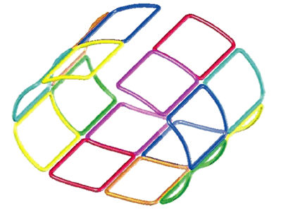
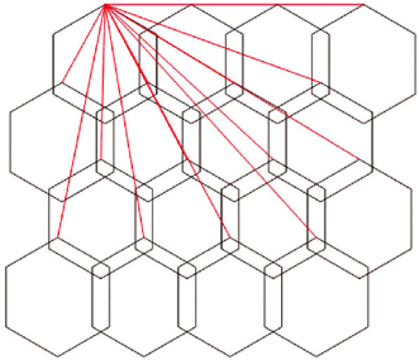
FIGURE 2.1 ● A 2D coil array, four antennas wide by four antennas long. The red lines represent the shields of the coaxial cables that must be attached to a common ground point.
As mentioned, cable traps may be used to control currents on the cable shields.5 Although these traps block current, they also may have large voltages induced on them during the transmit period. The amplitude of this voltage is much higher at 3T than at 1.5T, and the patient must be protected from this voltage (and the associated electric field), and the electrical components of the cable traps must be capable of routinely surviving these voltages. As with coil housings for 1.5T systems, only a small rise in temperature is acceptable.
Important design features for cables for a 3T versus a 1.5 system are:
  • Cables should be significantly shorter if possible.
  • More cable traps should be employed.
  • More insulation should be used to protect patients.
  • More care should be taken with the cable locations with respect to patients.
As previously discussed, a basic requirement for coils is that during the MR system body coil transmit period, the antennas must be “turned off.” Because the frequency of the B1 field is twice as high at 3T as at 1.5T, similarly sized coils have twice as much voltage induced in them during the MR system body coil transmit period. As a result, the decoupling trap voltages are twice as high and the power dissipated in the decoupling trap is four times as high unless the impedance of the trap is increased. Because decoupling traps are the locations for high voltages and currents, additional care must be taken at 3T to ensure that components do not fail, that arcing through the housing cannot occur, and that local electric fields associated with the trap cannot induce excessive power in the patient—s tissue.
Although 3T coil design requires precision and care, many of the technical challenges are being overcome, and coil arrays for 3T clinical scanners are rapidly becoming available.
Dedicated Coils
Many of the design requirements imposed upon RF coils arise from the design of the electrical interface of the MR system, requirements imposed by MR system manufacturers, flammability requirements, insulation requirements, laboratory standards, and requirements of local and international bodies such as the FDA, Canadian Standards Association, and the European requirements of IEC 601-1 and EN 60601-1. All of these design requirements are necessary, but not sufficient, to deliver a good image. Ultimately, the goal in designing new RF coils is to deliver imaging performance superior to that of existing coils or to address new imaging applications.
Only a few years ago, the lack of dedicated coils resulted in the use of head or knee coils to image the wrist, head coils to image the feet, or general-purpose coils to image the shoulder. Demand for superior imaging capability, however, has spawned an entire RF coil industry, resulting in the availability of many more RF coils dedicated to a particular application. As these new RF coils found their way into clinical practice, they set a new standard for imaging performance.
The most important factor determining the SNR performance of a coil is the volume of the RF coil. Since the SNR of an RF coil is almost directly proportional to its volume, imaging the wrist, for example, in a dedicated RF coil with a 10-cm diameter results in an image that is vastly superior to a wrist image acquired in a 16-cm-diameter knee coil.
Intuitively, it makes sense to place the receiving antenna (the RF coil) as close as possible to the source of the radio signals (the patient—s tissue). Figure 2.2, for example, illustrates how the knee coil housing is contoured to the shape of the knee. This results in SNR performance superior to that of a cylindrical RF coil. Of course, maximizing the number of patients for whom an RF coil will be suitable is also important: as the RF coil gets smaller, so does the patient population for whom it is suitable.
Transmit/Receive Versus Receive-Only Coils
Typically, the MR system body coil is used to transmit RF energy into the patient. Because the MR system body coil is

P.33


cylindrical, large, and far away from the patient, the resultant B1 RF transmit field is relatively uniform—that is, if the pulse sequence calls for a 90° proton tip angle, most of the hydrogen protons inside the patient that are within the MR system body coil are “tipped” about 90°. If the protons are not tipped approximately the same amount, the signal amplitudes received are different. As a result, similar tissues would exhibit different signal intensities depending upon where they are located. Contrast between tissues and even within the same tissue would be affected and could be misleading. For this reason, it is convenient to use the MR system body coil to excite the tissue of interest.

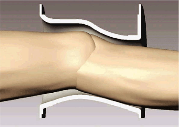
FIGURE 2.2 ● Cutaway view of a knee array coil housing showing a contoured fit for optimal SNR.
However, sometimes it is advantageous to use a local transmit coil. Such a coil transmits “locally,” into the knee for example, and also receives the signal back from the tissue. These types of coils are called local transmit coils or transmit/receive coils. For many years, the knee coils provided by several MR system manufacturers were transmit/receive. At first these coils were linear saddle coils. Later, quadrature birdcage or quadrature saddle pair coils were introduced. These coils (because they were cylindrical and could produce a relatively uniform B1 excitation field and because they were single-channel coils) lent themselves to transmitting RF energy into the knee through the coil and receiving the RF signal back from the knee through the same coil.
There are several benefits provided by a transmit/receive coil. First, only the tissue of interest, in this case the knee, is excited. This means that there is no unwanted signal returned to the coil from the rest of the body. This is particularly advantageous in the knee, where foldover (“wrap”) artifacts can emanate from the contralateral knee, or from tissue superior or inferior to the knee of interest. Second, RF power is deposited only into the patient—s knee, rather than into whatever part of the body is within the MR system body coil. Since the amount of RF energy required to “tip” the protons in just the knee is much less than the amount of RF energy required to tip the protons in the knee as well as all other tissues inside the MR system body coil, a transmit/receive knee coil deposits much less power (measured in Watts) into the patient. The FDA allows much higher power deposition (measured in Watts per kilogram of tissue) on a local basis than a whole-body basis. In addition, the patient is much better able to compensate for power that is deposited locally, through respiration, perspiration, and circulation.
Pulse sequences are now being developed to allow ultra-high-resolution imaging of cartilage at 1.5T. These pulse sequences are likely to exceed the allowable power deposition into the patient, known as the specific absorption rate (SAR), however, if the MR system body coil is used to transmit RF energy to the patient. Therefore, transmit/receive coils developed to address the SAR limitations will be needed for such high-resolution imaging.
At the 128-MHz operating frequency of 3T systems, the problem is magnified. To achieve the same tip angle in a 3T system, the RF power must increase by a factor of 4.
Transmit/Receive Knee Array Coil
A novel eight-channel transmit/receive knee array coil (Fig. 2.3) is available for most MR systems, at both 1.5T and 3T field strengths. The array comprises a cylindrical birdcage transmit antenna, with eight individual receive antennas inside of it that are contoured to the shape of the knee to minimize the volume. Keeping the birdcage transmit coil cylindrical produces a more uniform B1 transmit RF field. The “twist” in the birdcage has been shown to make the B1 field flatter in the superior/inferior direction, and to cause the B1 field to fall off more sharply at the ends of the coil. Since less tissue outside of the coil is being excited, there is less wraparound artifact and less unwanted signal entering the eight receive antennas.
Multichannel Coils
Most MR systems manufactured today have at least eight receivers or “channels.” Soon, however, 32-channel MR systems will be the norm. These multichannel systems were developed to take advantage of the principle of the phased array coil.6 The term “phased array,” borrowed from old RADAR terminology, is a misnomer because in MR imaging the array of coils receives multiple independent signals simultaneously as opposed to a single signal created from multiple sources in a “phased” manner.
The ability of the MR system to receive RF signals on many channels simultaneously provides a variety of benefits, including:
  • Higher SNR
  • Extended field of view
  • Ability to use parallel imaging techniques (see discussion below).
A typical modern RF coil consists of eight antenna elements mapped to eight receivers of the MR system. Such an array of antennas inside a single coil housing is known as an array coil. In an array coil, each antenna acts as a separate RF coil. As can be seen in Figure 2.4, the eight antenna elements are arrayed around a cylindrical phantom. Each antenna acts as an independent receiver of RF energy. The MR system combines all eight signals into a composite image. Signal intensity at the periphery of the phantom, close to the antennas, is

P.34


P.35


markedly increased. This is sometimes called the surface coil effect.

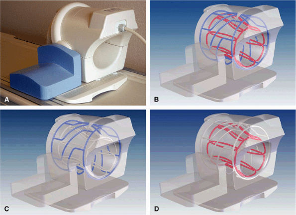
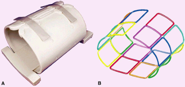
FIGURE 2.3 ● Eight-channel transmit/receive knee array coil. (A) Coil housing with base plate. (B) Antenna configuration inside coil housing. (C) Cylindrical twisted birdcage transmit antenna, for uniform B1 transmit field. (D) Eight individual receive antennas close to the knee, for optimal reception of signal.
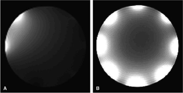
FIGURE 2.4 ● Typical eight-channel array coil. (A) One antenna turned on, with seven antennas decoupled. Note that they are not completely “off.” (B) A composite image with all eight antennas turned on.
SNR
SNR is affected by the size and number of antennas. If 16 antenna elements were arrayed around the cylinder shown in Figure 2.4, for example, they would not deliver higher SNR in the center of the phantom. However, because each of the 16 antennas would be about half as large as the 8 antennas illustrated, the SNR close to each antenna would be much higher. In other words, more channels result in higher “bulk” SNR. Often the region of interest is not precisely at the center of the coil. In the knee, for example, the patella, and substantial portions of the humeral head, and even the meniscus may not lie precisely in the center of the RF array coil. In this situation, more receiving antennas, which result in higher SNR, would produce more clinically relevant information.
It is important to remember that many small receiving antennas result in poor image uniformity, and the more antennas that are used, the smaller they must be. This results in high signal intensities near the antennas, regardless of the tissue being imaged. It imaging joints, a high degree of image homogeneity is important, and MR system manufacturers are adding image uniformity correction algorithms to their software to address this problem. These algorithms use the image intensity profile of the RF coil to remove intensity variations in the image. This can be accomplished during a calibration scan that compares an image acquired with the MR system body coil to the image acquired using the RF coil array.
As mentioned, to fit eight antennas around the knee, each antenna needs to be relatively small. The smaller the antenna, the higher the SNR under the antenna. This is because a small antenna receives both signal and noise from a small amount of tissue. Since noise is not encoded by the MRI process, the noise associated with a given image pixel is actually a coil sensitivity-weighted superposition of noise originating from everywhere around the coil. RF noise is produced by the random motion of charged particles within any resistive sample. Since resistive material (e.g., blood, muscle) is found inside the patient—s tissue and noise is amplified by the coil sensitivity in a particular region, the noise in an MR image comes from the area of the patient—s body near the coil where sensitivity is highest.
Isolating Adjacent Antennas
If two antennas, each resonating at 64 MHz (1.5T operating frequency), are brought toward each other, they start to have two combined resonance modes (a common mode and a counterrotating mode), and neither antenna will be an efficient receiver of RF signals at 64 MHz. As the antennas are brought even closer, the problem gets worse. However, as the antennas overlap one another, the problem is reduced. At some precise degree of overlap, the antennas cease to affect one another, and each resonates at 64 MHz once again. These antennas are said to be “isolated” from each other. The degree of isolation is measured in decibels. Antennas that are poorly isolated are “coupled” or have “mutual coupling.”
In a flat antenna array, antenna elements can easily be overlapped with their nearest neighboring antenna elements to achieve isolation. However, isolation between one antenna and its next nearest neighbor cannot generally be achieved in this way in dedicated extremity coils. If antenna elements are poorly isolated, or coupled to one another, the antennas tend to “talk” with one another (i.e., share signal and noise). As a result, the array advantage of having many independent coil elements is lost and the antenna array acts like one large antenna with lower SNR.
In a linear array of eight elements, for example, each element is overlapped with its nearest neighbors and is well isolated. If the array is bent into a cylinder, however, some antenna elements face one another, and the degree of coupling between antenna elements that are not overlapped increases dramatically. Isolation is complicated even in a four-element antenna array: antenna 1 must be isolated from antennas 2, 3, and 4; antenna 2 must be additionally isolated from antennas 3 and 4; and so on. In total, 3 + 2 + 1 = 6 individual isolations must be achieved. In an ideal 32-channel antenna array, 31 + 30 + … 1 = 496 isolations are necessary for optimal coil performance.
Although designing and manufacturing many-channel coil arrays is a huge task compared to the last generation of four-channel coil arrays, there are a variety of techniques and trade secrets for improving isolation of the antenna elements of an array coil. One commonly employed method is to use a low-impedance preamplifier on each antenna element. This approach allows each coil impedance to be high enough to minimize coil currents and thus reduce coil coupling effects. Most MR systems being manufactured today allow for the use of such preamplifiers.
Parallel Imaging Techniques
Parallel imaging techniques are innovative methods now available on nearly all new MR systems. These methods generally use the RF coil sensitivity profile to reduce the number of phase encode steps required to generate an image7 and work only with array coils. Reducing the number of phase encode steps allows an image to be acquired much more quickly (called acceleration) and has been shown to be very useful when imaging flow or organs subject to motion, such as the heart or lungs. The reduced acquisition times result in higher-quality images of these moving tissues, even though SNR is significantly reduced when acceleration factors are employed.
Modern RF coils are being designed to take advantage of these methods. Antenna array elements must be laid out in a specific direction to permit an acceleration in that direction. For example, if an antenna array has two elements in the coronal plane, the acquisition of a coronal image can be accelerated by a factor of 2. Imaging time can be cut in half. The caveat is that the resulting SNR is reduced by at least 1/√2, or 0.707, of the original SNR. Since this has the same result as reducing the number of averages in half, parallel imaging was thought to be of little use unless the number of averages was not already equal to 1.

P.36


Orthopaedic images are generally acquired with two or four averages, since one average rarely provides the necessary SNR to produce a good high-resolution, small-field of view image. Since acceleration results in a significant reduction in SNR, parallel imaging was initially though to have no application in joint imaging (other than dynamic joint imaging). Although some MR systems today are capable of using parallel imaging accelerations while acquiring multiple averages, the application of parallel imaging techniques in orthopaedic imaging is still in its infancy. Some users are very enthusiastic, stating that acquisition of images in less time, and then averaging them together to regain SNR, results in images with significantly reduced motion artifact. Although this remains to be clearly demonstrated, there is an important use of parallel imaging in evaluation of joints. Using a parallel imaging technique with an acceleration factor of 1 (i.e., no acceleration), the array coil sensitivity profile can be applied to correct any nonuniformities in the image. This is an excellent technique for the correction of image nonuniformities caused by many small antennas producing high signal intensities, and MR system manufacturers have begun making it available.
Because parallel imaging reduces the number of phase encode steps needed to create an image, using parallel imaging can reduce the SAR associated with a particular acquisition.7 This may prove useful for 3T sequences where body coil excitation is used (e.g., shoulder and hip imaging).
RF Coils for Orthopaedic Imaging
Dedicated eight-channel RF array coils for orthopaedic imaging are becoming available for 1.5T MR systems. Clinical prototypes have demonstrated that these coils can deliver SNR increases that result in increased diagnostic confidence and, in some cases, increased diagnostic capability. As array coil designs become available for 3T MR systems, faster, higher-resolution joint imaging will become possible. Orthopaedic imaging at 3T has proved to be less challenging than body imaging at 3T, since the dielectric resonance effect at 3T is not as severe in joints.
Knee coils were discussed earlier in the section on the Transmit/Receive Knee Array Coil.
Shoulder Array
Designing a shoulder array is particularly challenging because shoulders vary so much in size and the coil needs to be able to accommodate both left and right extremities. In addition, the chest size and shape vary (barrel-chested to flat-chested), and the pectoral muscles may be prominent (as in body builders). Imaging female patients with breast implants can also be problematic, since the implant may hinder proper placement of the coil. Deep penetration is required to image the anterior labrum, whereas the rotator cuff and the acromion are very shallow. Too much penetration induces motion artifact from the lung. Another complication stems from the fact that patients tend to unknowingly shrug their shoulders while breathing. Fixing the coil to a base plate is helpful in reducing patient motion because the patient can feel resistance to movement of the shoulder and is more aware of moving.
Because of cost considerations, it is not feasible to have multiple coils of varying size for each shoulder, and the solution was to create an adjustable hinged coil that can be used for both the right and left shoulders (Fig. 2.5). The hinges allow the “wings” of the coil to move in the anterior/posterior (A/P) direction, allowing the spread of the wings to be adjusted to the patient—s body habitus. The coil can open wide to image large shoulders or can be closed down to a 14-cm aperture for small shoulders. The hinges lock to provide resistance to patient motion. The coil is mechanically fixed to a base plate in the A/P direction to minimize motion-induced artifacts. The coil must be flipped over to image the contralateral shoulder; therefore, fixing the coil to the base plate must be simple and intuitive yet robust.
Although the coil housing has hinges, the housing is rigid. This allows control of overlap of the antenna elements to maintain isolation. Preamplifier decoupling assists in maintaining isolation between those antenna elements that face each other and change orientation as the wings are repositioned. The preamplifiers are located in the box attached to the coil, since the limited space between the patient and the

P.37


body coil precludes placing the preamplifiers directly on the antenna elements.

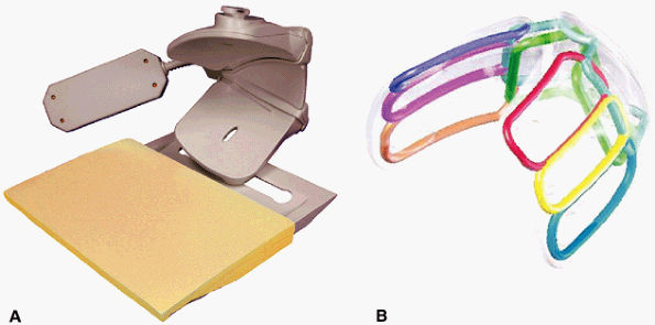
FIGURE 2.5 ● A dedicated eight-channel shoulder array. (A) Shoulder array shown fixed to the base plate. (B) Antenna geometry for the eight-channel shoulder array.
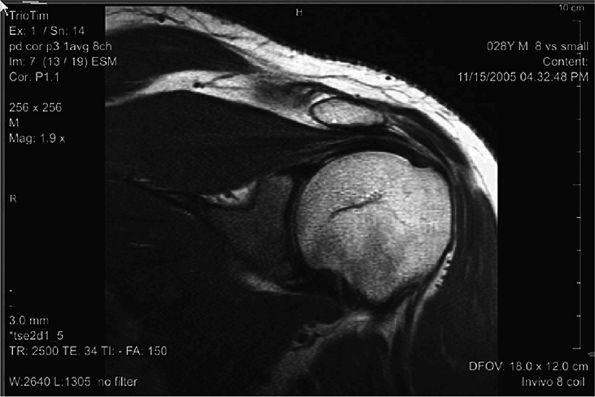
FIGURE 2.6 ● Image of the shoulder acquired at 3T using an eight-channel shoulder array. Slice thickness is 3 mm with 0.47 × 0.47 mm in-plane resolution.
The coil supports a parallel image acceleration factor of three in each direction (A/P, left/right, superior/inferior [S/I]) (Fig. 2.6), considerably improving imaging time; Figure 2.6 was acquired in less than 90 seconds.
Hip Array
The coil for the dedicated hip array (Fig. 2.7) is flexible, since there is such a wide variation in body habitus. In some patients, posterior fat causes the buttocks to protrude laterally in the supine position. The hip array is designed so that it wraps around the patient. For small patients it may close completely, with a controlled overlap of antenna elements where they meet at the patient—s midline. For large patients, there is a controlled separation of antenna elements at the patient—s midline to ensure that the antenna elements do not detune each other.
As with similar shoulder imaging, hip imaging requires small fields of view with high resolution. The individual antenna elements need to be large enough to exhibit good depth of penetration to the acetabulum, but not so large that they cover unwanted tissue superior or inferior to the area of interest. Bilateral imaging is desirable, but unilateral imaging is required to achieve the small field of view and high resolution necessary.
To meet these requirements, the antenna elements are positioned to image the hip joint from the anterior, lateral, and posterior approaches. Sixteen antennas are used, eight targeted at each hip. The coil supports three modes of operation: left hip with eight channels, right hip with eight channels, or bilateral imaging with all channels. The coil antennas that are active may be chosen from the MR console. MR systems equipped with 16 or more receivers can use all 16 channels. For MR systems with eight channels, the 16 antenna elements are combined into eight channels for bilateral imaging.
The coil supports a parallel imaging acceleration factor of at least 2 in the coronal and sagittal planes and 4 in the axial plane. Bilateral acquisitions can theoretically be acquired with an acceleration factor of 8, but the need for SNR will dictate what acceleration factors are practical.
FIGURE 2.7 ● Dedicated hip array. (A) 16-channel hip array. There are 8 channels for each hip. (B) Antenna configuration for the 16 antennas.

P.38


Wrist Array
The wrist array coil (Fig. 2.8) is an eight-channel receive-only design. This coil is contoured to the wrist and hand to minimize the volume of the coil. The S/I coverage is 11 cm, with coverage extending distally to the metacarpals.
The mechanical design of the coil incorporates a hinged cover that allows accurate visual centering of the wrist inside the coil. Once the wrist is properly positioned, pads can be added inside the coil, and the cover can be closed and locked. One of the pads applies pressure on the palm, which presses the back of the hand into a single plane. The objective is to align the carpal ligaments so they are visible in the same imaging plane.
The coil can be used in several positions. The most comfortable is at the patient—s side (see Fig. 2.8C). Because magnet homogeneity can sometimes degrade off isocenter near the body coil, resulting in poor fat saturation, it is desirable to position the coil as far medially as possible. The coil can also be used over the patient—s head in the “Superman” position (see Fig. 2.8D). This allows positioning the coil at the most homogeneous location in the magnet. This wrist array coil allows images to be acquired with very small fields of view and at very high resolutions (Fig. 2.9).
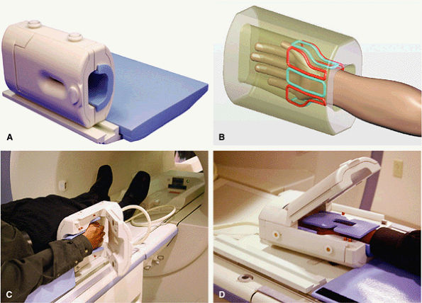
FIGURE 2.8 ● An eight-channel receive-only wrist array coil. (A) Wrist array coil with a window and a hinged cover. (B) Eight elements surround the wrist. (C) The wrist array positioned at the patient—s side. At such a distance from the isocenter, magnet homogeneity can sometimes be problematic, resulting in poor fat saturation. (D) The “Superman” position locates the coil near the magnet isocenter, where B0 field homogeneity is better. This leads to significant improvements in fat saturation.
Foot and Ankle Array Coil
The foot and ankle array coil is an eight-channel coil designed for high-resolution imaging (Fig. 2.10). The patient—s foot is strapped into the foot support and pads are applied under the heel. Although the preferred imaging position is dorsal flexion, many patients cannot tolerate that position after injury. The coil may be tilted 15° from the dorsal flex position for patient comfort.
The coil has three modes of operation: ankle, forefoot, and entire foot and ankle (Fig. 2.11). The mode of operation is chosen from the MR system console. Different modes are necessary because of variations in the length of the foot. The small fields of view sometimes prescribed for the ankle may exhibit wraparound artifact if the forefoot antenna elements were left active, and vice versa. The entire foot and ankle mode is useful for MR angiography studies and whole-foot studies.
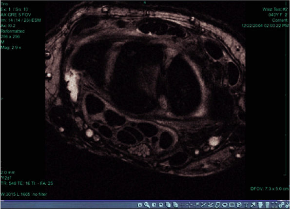
FIGURE 2.9 ● High-resolution image acquired with a 3T version of the wrist array coil. Note the nerve bundle.
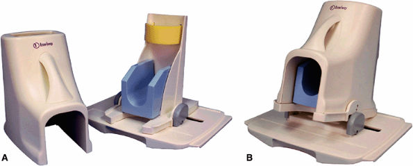
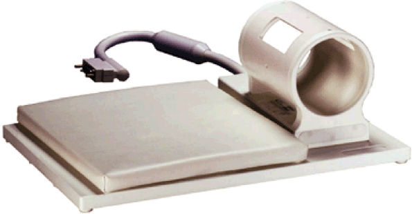
FIGURE 2.10 ● Foot and ankle array coil. (A) RF coil with base plate positioner. (B) The base plate provides up to 15° of dorsal flex for patient comfort.
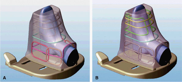
FIGURE 2.11 ● Modes of operation of the foot and ankle array coil. (A) In the ankle mode of operation, six of the eight antennas are active. The forefoot solenoid and saddle pair are not active. (B) In the forefoot mode of operation, three antennas are active: a single-turn solenoid, a 2-turn solenoid, and a saddle pair.

P.39


P.40


An array of eight antennas surrounds the foot and ankle (Fig. 2.12). The forefoot is surrounded by three coils. The yellow coil is a two-turn solenoid, the blue coil is a single-turn solenoid, and the green coil is a saddle pair. Solenoids have been shown to be remarkably efficient coils. In fact, the ultimate coil is a solenoid that has the tissue of interest in the middle of the loop. Solenoid coils must be positioned so that the plane of the solenoid is parallel to the B0 field of the magnet. If the solenoid is positioned with the B0 perpendicular to the plane of the loop, the coil receives very little signal.
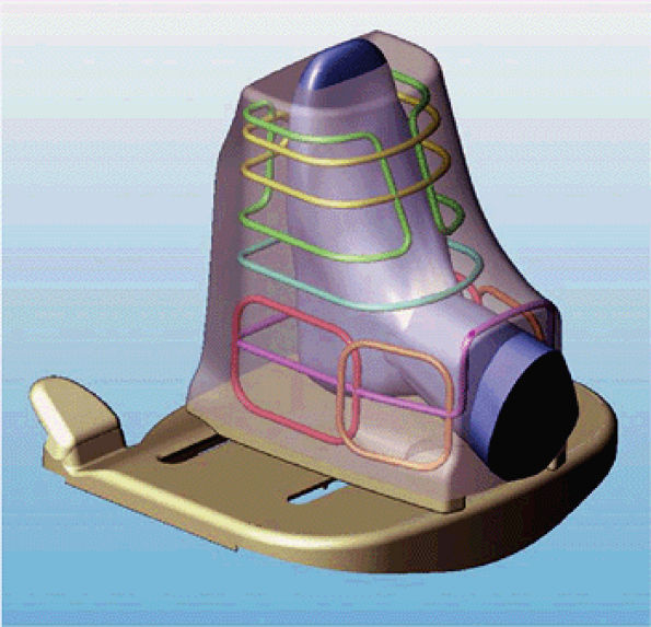
FIGURE 2.12 ● Antenna configuration for foot and ankle array.
Elbow Coil
An eight-channel upper extremity coil (Fig. 2.13) is typically used for imaging the elbow, although it can be used for other small structures for which a dedicated coil is not available. Wrist images acquired with this coil, while of reasonable quality, do not rival those acquired with a dedicated wrist array.
FIGURE 2.13 ● Eight-channel upper extremity coil.
Since the coil is quite easily slid up the arm, it does not split in the center, avoiding the expense and reliability issues associated with the many RF feedthroughs that would be needed to connect the antennas if the coil did split. Windows in the coil allow for visual centering of the elbow within the coil.
References
1. Foster MA. Magnetic resonance in medicine and biology. New York: Pergamon Press, 1984.
2. Roemer PB, Edelstein WA, Hayes CE, et al. The NMR phased array. Magn Reson Med 1990;16:192-225.
3. Buchli R, Saner M, Meier D, et al. Increased RF power absorption in MR imaging due to RF coupling between body coil and surface coil. Magn Reson Med 1989;9(1):105-112.
4. Chen CN, Hoult DI. Signal and noise. In: Biomedical magnetic resonance technology. New York: Adam Hilger, 1989:118.
5. Peterson D, Beck BL, Duensing GR. Proceedings of the International Society of Magnetic Resonance in Medicine, 2002:850.
6. Pruessmann KP. Parallel imaging at high field strength: synergies and joint potential. Topics MRI 2004;15:237-244.


This website uses cookies to improve your experience. We'll assume you're ok with this, but you can opt-out if you wish. Accept Read More