Surface Coil Imaging
designed to pick up signals at the frequency of interest and deliver them to a receiver.
-
Resistance
-
Inductance
-
Capacitance
 |
|
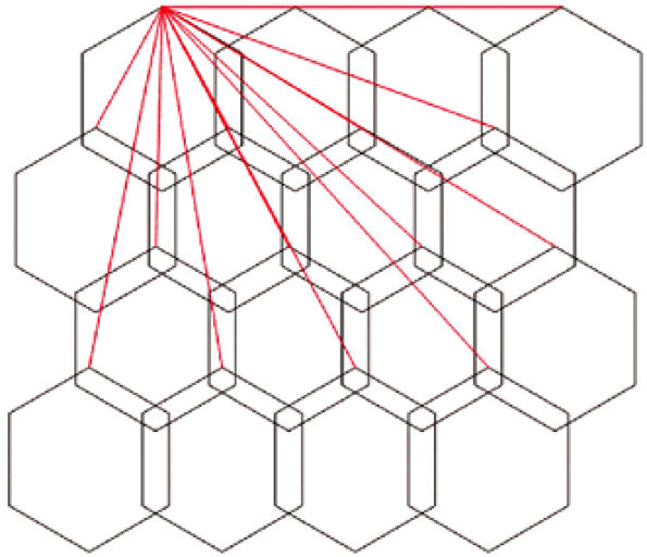
FIGURE 2.1 ● A 2D coil array, four antennas wide by four antennas long. The red lines represent the shields of the coaxial cables that must be attached to a common ground point.
|
-
Cables should be significantly shorter if possible.
-
More cable traps should be employed.
-
More insulation should be used to protect patients.
-
More care should be taken with the cable locations with respect to patients.
cylindrical, large, and far away from the patient, the resultant B1 RF transmit field is relatively uniform—that is, if the pulse sequence calls for a 90° proton tip angle, most of the hydrogen protons inside the patient that are within the MR system body coil are “tipped” about 90°. If the protons are not tipped approximately the same amount, the signal amplitudes received are different. As a result, similar tissues would exhibit different signal intensities depending upon where they are located. Contrast between tissues and even within the same tissue would be affected and could be misleading. For this reason, it is convenient to use the MR system body coil to excite the tissue of interest.
 |
|
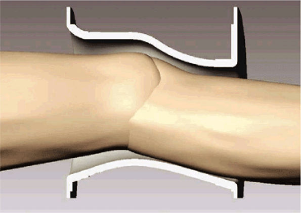
FIGURE 2.2 ● Cutaway view of a knee array coil housing showing a contoured fit for optimal SNR.
|
-
Higher SNR
-
Extended field of view
-
Ability to use parallel imaging techniques (see discussion below).
markedly increased. This is sometimes called the surface coil effect.
 |
|
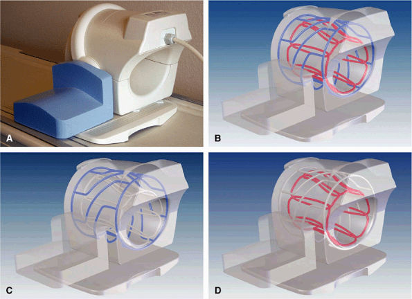
FIGURE 2.3 ● Eight-channel transmit/receive knee array coil. (A) Coil housing with base plate. (B) Antenna configuration inside coil housing. (C) Cylindrical twisted birdcage transmit antenna, for uniform B1 transmit field. (D) Eight individual receive antennas close to the knee, for optimal reception of signal.
|
 |
|
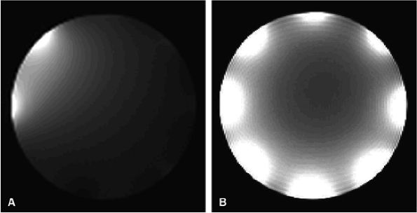
FIGURE 2.4 ● Typical eight-channel array coil. (A) One antenna turned on, with seven antennas decoupled. Note that they are not completely “off.” (B) A composite image with all eight antennas turned on.
|
body coil precludes placing the preamplifiers directly on the antenna elements.
 |
|
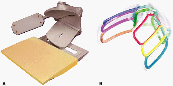
FIGURE 2.5 ● A dedicated eight-channel shoulder array. (A) Shoulder array shown fixed to the base plate. (B) Antenna geometry for the eight-channel shoulder array.
|
 |
|
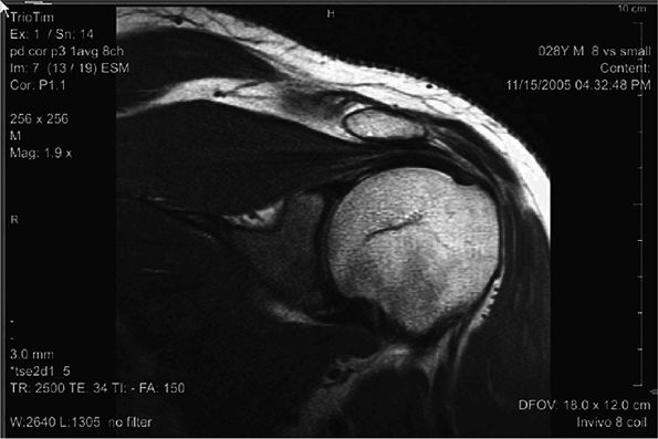
FIGURE 2.6 ● Image of the shoulder acquired at 3T using an eight-channel shoulder array. Slice thickness is 3 mm with 0.47 × 0.47 mm in-plane resolution.
|
 |
|
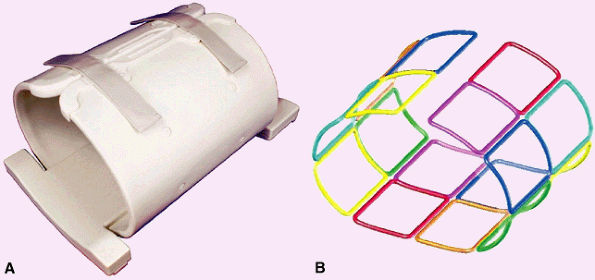
FIGURE 2.7 ● Dedicated hip array. (A) 16-channel hip array. There are 8 channels for each hip. (B) Antenna configuration for the 16 antennas.
|
 |
|
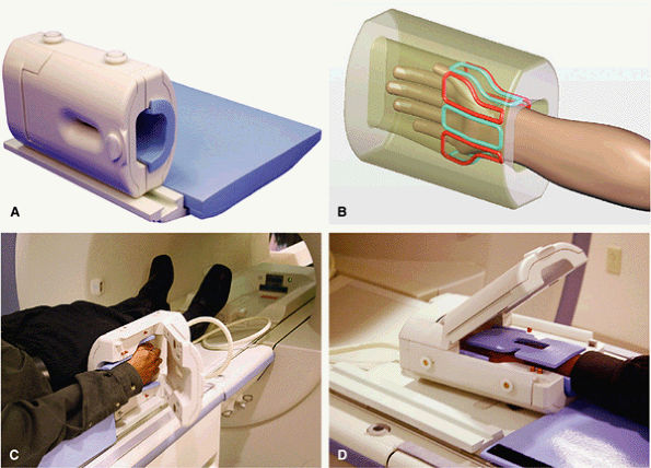
FIGURE 2.8 ● An eight-channel receive-only wrist array coil. (A) Wrist array coil with a window and a hinged cover. (B) Eight elements surround the wrist. (C) The wrist array positioned at the patient—s side. At such a distance from the isocenter, magnet homogeneity can sometimes be problematic, resulting in poor fat saturation. (D) The “Superman” position locates the coil near the magnet isocenter, where B0 field homogeneity is better. This leads to significant improvements in fat saturation.
|
 |
|
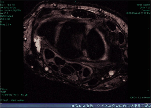
FIGURE 2.9 ● High-resolution image acquired with a 3T version of the wrist array coil. Note the nerve bundle.
|
 |
|
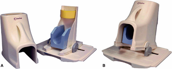
FIGURE 2.10 ● Foot and ankle array coil. (A) RF coil with base plate positioner. (B) The base plate provides up to 15° of dorsal flex for patient comfort.
|
 |
|
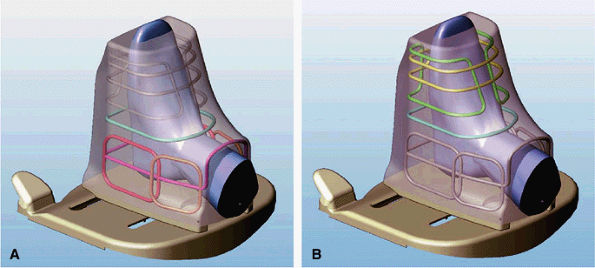
FIGURE 2.11 ● Modes of operation of the foot and ankle array coil. (A) In the ankle mode of operation, six of the eight antennas are active. The forefoot solenoid and saddle pair are not active. (B) In the forefoot mode of operation, three antennas are active: a single-turn solenoid, a 2-turn solenoid, and a saddle pair.
|
 |
|
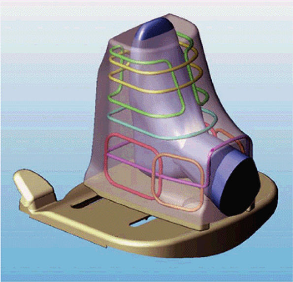
FIGURE 2.12 ● Antenna configuration for foot and ankle array.
|
 |
|
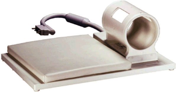
FIGURE 2.13 ● Eight-channel upper extremity coil.
|

