
Editors: Berry, Daniel J.; Steinmann, Scott P.
Title: Adult Reconstruction, 1st Edition
Copyright ©2007 Lippincott Williams & Wilkins
> Table of Contents > Section 1 – HIP > Part A – Evaluation > 2 – Imaging of the Hip
2
Imaging of the Hip
Bryan D. Springer
Over the past several decades there have been
significant technologic advances in the field of radiology including
computed tomography, magnetic resonance imaging, and nuclear medicine.
Plain radiography, however, remains the initial diagnostic imagining
study of choice and should serve as the first step in the radiographic
evaluation of the hip.
The goal of any imaging study is to confirm or provide a
diagnosis of a disorder. For any imaging modality to be useful, it must
be performed and interpreted accurately. This chapter outlines the
screening radiography of the hip along with special views and
additional modalities that may be useful in evaluating a patient with
suspected hip pathology.
diagnosis of a disorder. For any imaging modality to be useful, it must
be performed and interpreted accurately. This chapter outlines the
screening radiography of the hip along with special views and
additional modalities that may be useful in evaluating a patient with
suspected hip pathology.
Plain Radiography (X-Ray View)
Every patient with suspected hip pathology should
undergo a screening radiographic examination. For evaluation of the
pelvis and hips, this should include anterior-posterior pelvis (AP
pelvis) and cross-table or frog-leg lateral views. The findings on
screening radiography allow for identification of initial pathology and
enable the physician to make a more directed radiographic evaluation
with special views or other imaging modalities.
AP Pelvis
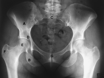
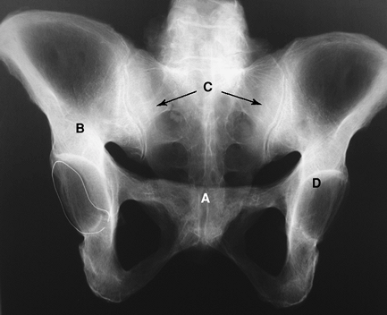
The AP pelvis radiograph (Fig. 2-1)
is performed with the patient supine on the x-ray table. The legs are
internally rotated 15 degrees to compensate for normal femoral
anteversion. The beam should be directed centrally to view the entire
pelvis. This view allows for imaging of the iliac bones, sacrum, pubis,
ischium, femoral heads, and acetabulum and the proximal aspect of the
femur including the greater and lesser trochanter.
Cross-Table Lateral
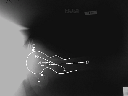
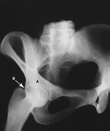
The cross-table lateral or groin lateral view (Fig. 2-2)
is obtained with the patient supine on the examination table and the
opposite hip flexed and abducted. The x-ray cassette is placed on the
outside of the affected hip, and the beam is angled from the opposite
side toward the patient’s groin. This view provides a lateral image of
the femoral head allowing for assessment of anteversion angle of the
femoral neck, which can range from 25 to 30 degrees. It also allows for
visualization of the ischial tuberosity and the anterior and posterior
margins of the acetabulum.
Frog-Leg Lateral
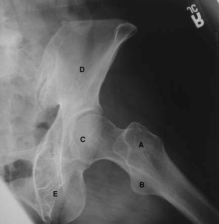
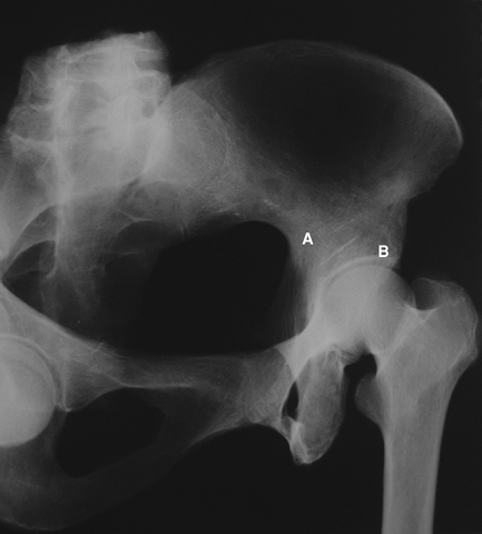
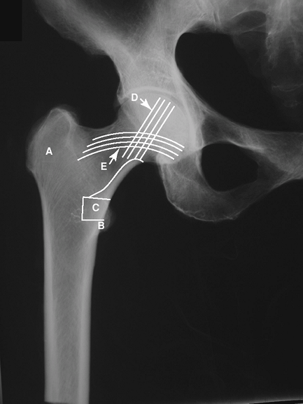
The frog-leg lateral view (Fig. 2-3)
is performed with the patient supine on the x-ray table with the knees
flexed and the thigh maximally abducted. The beam is directed either
vertically or with 10 to 15 degrees of cephalad tilt. This projection
demonstrates the lateral aspect of the femoral head and both
trochanters.
is performed with the patient supine on the x-ray table with the knees
flexed and the thigh maximally abducted. The beam is directed either
vertically or with 10 to 15 degrees of cephalad tilt. This projection
demonstrates the lateral aspect of the femoral head and both
trochanters.
Special Views
Ancillary views for the pelvis and hips can often provide essential additional information to screening radiography.
Pelvis
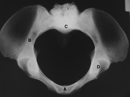
The inlet and outlet views of the pelvis are used in
addition to the AP pelvis for evaluation of the bony pelvis. The inlet
view (Fig. 2-4) projects the rings of the pelvis and allows for evaluation of rotational alignment of the pelvis. The outlet view (Fig. 2-5)
projects parallel to the pelvic rim and perpendicular to the sacrum and
allows for evaluation of vertical translation or malalignment.
Acetabulum
Judet oblique views of the pelvis and acetabulum are
obtained by rotating the patient 45 degrees from the supine position
with the beam directed anteroposteriorly. They allow for visualization
of the columns and walls of the acetabulum and are used in evaluation
and classification of acetabular fractures as well as in the evaluation
of bone loss and osteolysis in patients with a failed acetabular
component. The two views are as follows:
Anterior oblique.
The anterior oblique or “obturator oblique” view (Fig. 2-6) demonstrates the anterior column and the posterior wall of the acetabulum.
P.9
Posterior oblique.
The posterior oblique or “iliac oblique” view (Fig. 2-7) demonstrates the posterior column and the anterior wall of the acetabulum.
 |
|
Figure 2-1 Anterior-posterior (AP) view of the pelvis. A, ilium; B, ischium; C, sacrum; D, acetabulum; E, femoral head; F, greater trochanter; G, pubic symphysis.
|
Radiographic Landmarks of the Pelvis and Femur
Pelvis
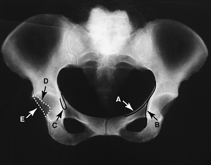
Radiographic landmarks of the pelvis (Fig. 2-8) are as follows:
-
Iliopectineal line: denotes anterior column
-
Ilioischial line: denotes posterior column
-
Teardrop: inferior margin of the medial acetabular border.
-
Anterior acetabular rim
-
Posterior acetabular rim
 |
|
Figure 2-2 Cross-table lateral view of the pelvis and femur. A, greater trochanter; B, femoral head; C, femoral shaft; D, ischium; E, anterior margin of acetabulum; F, posterior margin of acetabulum; G, angle of femoral anteversion.
|
 |
|
Figure 2-3 Frog-leg lateral view of the pelvis and femur. A, greater trochanter; B, lesser trochanter; C, femoral head; D, ilium; E, ischium.
|
Femur
Radiographic landmarks of the femur (Fig. 2-9) are as follows:
-
Greater trochanter
-
Lesser trochanter
-
Calcar femoris: intramedullary lamellar (compact) bone along medial femoral neck through the lesser trochanter
-
Primary compressive trabecular bands
-
Primary tensile trabecular bands
 |
|
Figure 2-4 The inlet view of the pelvis. A, pubic symphysis; B, ilium; C, sacral promontory; D, acetabulum.
|
P.10
 |
|
Figure 2-5 The outlet view of the pelvis. A, pubic symphysis; B, ilium; C, sacrum/sacroiliac (SI) joints; D, acetabulum.
|
Radiographic Measurement of the Hip
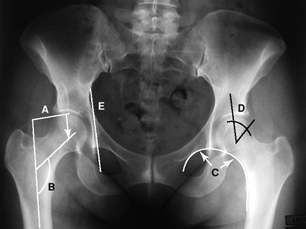
Radiographic measurement of the hip (Fig. 2-10) involves examination of the following:
Femoral offset: Horizontal distance from the center of the femoral head to the center of the femoral shaft.
Femoral neck shaft angle: Angle measured between the
central line of the femoral neck and shaft. Normal 125 degrees with a
range of 120 to 140 degrees.
central line of the femoral neck and shaft. Normal 125 degrees with a
range of 120 to 140 degrees.
 |
|
Figure 2-6 The anterior oblique or obturator oblique Judet view of the pelvis. A, anterior column of pelvis; B, posterior wall of acetabulum.
|
 |
|
Figure 2-7 The posterior oblique or iliac oblique Judet view of the pelvis. A, posterior column of pelvis; B, anterior wall of acetabulum.
|
Shenton line: Observed as a confluent arch between the
inferior border of the superior pubic ramus and the medial border of
the femoral neck. Helpful in evaluating the relationship of the femoral
head to the acetabulum. A break in the Shenton line indicates migration
of the femoral head.
inferior border of the superior pubic ramus and the medial border of
the femoral neck. Helpful in evaluating the relationship of the femoral
head to the acetabulum. A break in the Shenton line indicates migration
of the femoral head.
 |
|
Figure 2-8 Radiographic landmarks of the pelvis. A, iliopectineal line; B, ilioischial line; C, acetabular teardrop; D, anterior acetabular rim; E, posterior acetabular rim.
|
P.11
Center edge angle of Wiberg: A line is drawn from the
center of the femoral head to the edge of the acetabulum. A second line
is drawn vertically to the center of the femoral head to form the
incident angle.
center of the femoral head to the edge of the acetabulum. A second line
is drawn vertically to the center of the femoral head to form the
incident angle.
 |
|
Figure 2-9 Radiographic landmarks of the femur. A, greater trochanter; B, lesser trochanter; C, calcar femoris; D, primary compressive trabecular bands; E, primary tensile trabecular bands.
|
Kohler Line: A line is drawn from the medial border of
ischium to the medial border of ilium. Penetration medial to this line
indicates protrusion.
ischium to the medial border of ilium. Penetration medial to this line
indicates protrusion.
Radiographic Characteristics of Osteoarthritis of the Hip
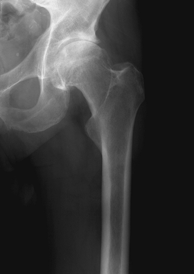
The hip and knee are the most common sites of osteoarthritis (Fig. 2-11).
Symptoms may vary from stiffness to pain to difficulty walking. The
severity of symptoms may not always correlate with radiographic
severity. The classic radiographic features of osteoarthritis include
the following:
Symptoms may vary from stiffness to pain to difficulty walking. The
severity of symptoms may not always correlate with radiographic
severity. The classic radiographic features of osteoarthritis include
the following:
-
Joint space narrowing as a result of articular cartilage loss
-
Subchondral sclerosis or eburnation of bone
-
Osteophyte (bone spur) formation as a
result of an attempted reparative process in areas subject to stress.
Osteophytes often develop at the periphery or margin of the joint. -
Formation of bone cyst from intrusion of synovial fluid into the bone.
-
Migration of the femoral head relative to the acetabulum.
 |
|
Figure 2-10 Radiographic landmarks of the femur. A, femoral offset; B, femoral neck shaft angle; C, Shenton line; D, center edge angle of Wiberg; E, Köhler line.
|
Imaging of the Prosthetic Hip
Evaluation of a patient with a prosthetic hip requires a
thorough and complete radiographic assessment. Adequate radiographs
should show the entire prosthesis and any surrounding cement. In most
cases, plain radiographs will provide adequate information for the
diagnosis, and ancillary
thorough and complete radiographic assessment. Adequate radiographs
should show the entire prosthesis and any surrounding cement. In most
cases, plain radiographs will provide adequate information for the
diagnosis, and ancillary
P.12
imaging (CT scan, bone scan) is needed only in selected circumstances.
 |
|
Figure 2-11 Radiographic characteristics of osteoarthritis of the hip.
|
 |
|
Figure 2-12 Anteroposterior pelvis radiograph demonstrating a dislocated total hip arthroplasty.
|
 |
|
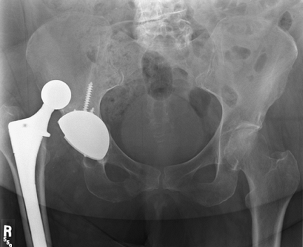
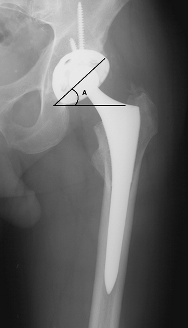
Figure 2-13 Anteroposterior pelvis radiograph demonstrating appropriate acetabular abduction. A, abduction angle of acetabular component.
|
Some common complications of arthroplasty often identified on plain radiographs include the following:
-
Component malposition or dislocation
-
Aseptic loosening of cemented or uncemented prostheses
-
Osteolysis or bone reabsorption secondary to wear debris of prosthetic materials
-
Infection
-
Periprosthetic fracture
Component dislocation may occur at any time after surgery (Fig. 2-12).
A common cause of early dislocation is component malposition. AP
radiograph should demonstrate approximately 45 degrees of abduction (Fig. 2-13).
Assessment of acetabular anteversion can be obtained from a true
lateral radiograph. Appropriate acetabular component anteversion is 10
to 30 degrees. Occasionally CT scan to directly demonstrate femoral and
acetabular component position may be required.
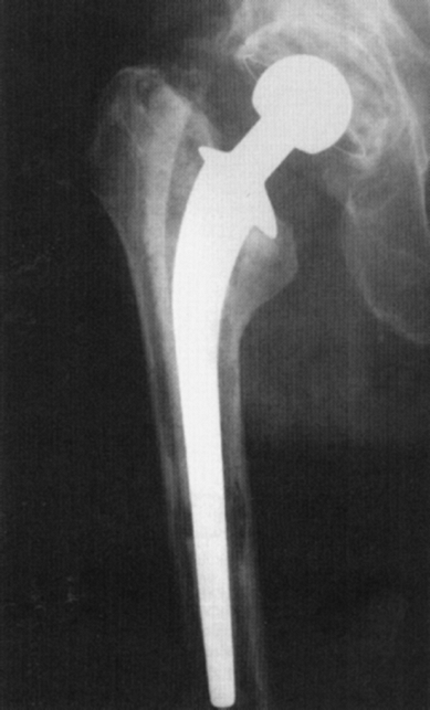
Aseptic loosening (Fig. 2-14) of
either the femoral or acetabular components is a common cause of
failure of the prosthetic hip. Radiographic changes can be subtle and
either the femoral or acetabular components is a common cause of
failure of the prosthetic hip. Radiographic changes can be subtle and
P.13
often
require the evaluation of serial radiographs taken over a period of
time. Different mechanisms and patterns of failure exist for loosening
of cemented and uncemented prosthesis. Table 2-1 lists the common radiographic findings of aseptic loosening of a total hip arthroplasty.
 |
|
Figure 2-14 Anteroposterior radiograph of the femur demonstrates aseptic loosening of the femoral component.
|
|
TABLE 2-1 Radiographic Criteria of Aseptic Loosening
|
||||||||||||
|---|---|---|---|---|---|---|---|---|---|---|---|---|
|
 |
|
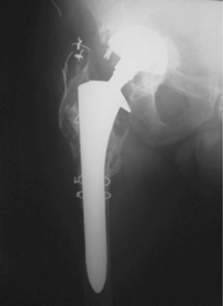
Figure 2-15 Anteroposterior radiograph of the femur demonstrates periprosthetic bone resorption secondary to infection.
|
Infection (Fig. 2-15) continues
to be one of the most devastating complications for the patient and
surgeon following prosthetic hip replacement. Infection may be seen as
an acute process or may be chronic. Radiographic findings in the acute
setting are often absent and in the chronic setting may be subtle. The
chronically infected prosthetic joint may present with periprosthetic
bone resorption, frank bony destruction, and mechanical failure of the
prosthesis.
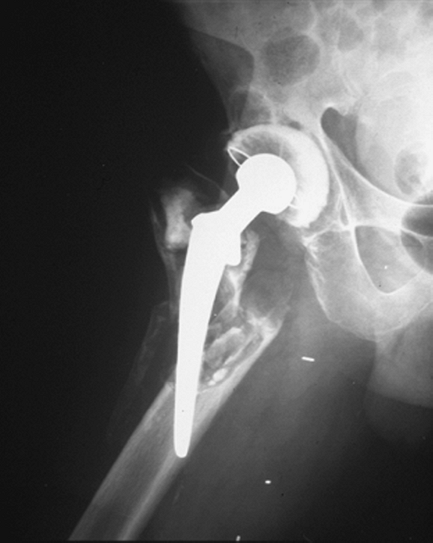
Periprosthetic fractures (Fig. 2-16)
are often the result of a fall or trauma resulting in a fracture of the
bone around the prosthesis. The pattern is often described as being
around the implant, at the tip of the implant, or distal to the
implant. The prosthesis may continue to be well fixed despite the
fracture or be loose as a result of the fracture of the surrounding
supportive bone.
Ancillary Imaging
The cause of hip pain can be occult. Additional
information not available on plain radiographs oftentimes is required
to properly diagnose and treat certain disorders. In these situations,
ancillary imaging techniques may be helpful. The most commonly used
techniques include computed tomography, magnetic resonance imaging, and
bone scintigraphy.
information not available on plain radiographs oftentimes is required
to properly diagnose and treat certain disorders. In these situations,
ancillary imaging techniques may be helpful. The most commonly used
techniques include computed tomography, magnetic resonance imaging, and
bone scintigraphy.
P.14
 |
|
Figure 2-16 Periprosthetic fracture around the stem of a total hip arthroplasty.
|
 |
|
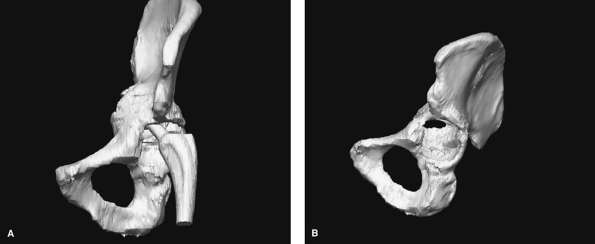
Figure 2-17 Computer tomography 3D reconstruction of the pelvis with components in place (A) and with prosthesis subtracted (B) demonstrating severe protrusion defect of acetabular bone but intact anterior and posterior columns.
|
Computed Tomography
Computed tomography is most commonly used to evaluate
primary disorders of the hip, assess pelvic bone quality, and aid in
the postoperative evaluation of prosthetic component positioning. The
latest generation of CT scanners use multiple detectors that allow for
improved resolution. Reconstruction algorithms allow the generation of
reformatted and three-dimensional images (Fig. 2-17A, B). These techniques are particularly useful in regions with complex anatomy such as the pelvis.
 |
|
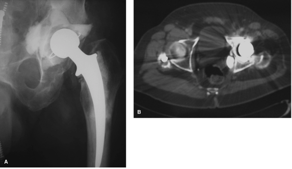
Figure 2-18 Preoperative radiograph of a 68-year-old man with an infected left total hip arthroplasty (A) with retained intrapelvic cement confirmed on CT scan (B) that required removal during surgery.
|
For patients who present for complex revision of a
failed acetabular component, CT scans can aid in determining the
adequacy of remaining bone stock in patients with protrusio defects or
pelvic discontinuity. In addition, CT allows for localization of
intrapelvic cement and retained hardware in relationship to intrapelvic
vasculature (Fig. 2-18A, B). A CT scan may also be useful for assessing component position in the clinical setting of recurrent prosthetic instability.
P.15
The evaluation of acetabular or femoral component ante- version in
relationship to fixed bony landmarks may provide useful information
prior to revision surgery.
 |
|
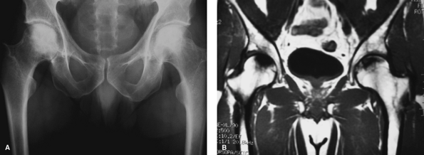
Figure 2-19 Radiographs (A) and T1-weighted magnetic resonance imaging (B) of a 50-year-old man with bilateral avascular necrosis of the hips.
|
Magnetic Resonance Imaging
Magnetic resonance imaging (MRI) has gained wide
acceptance in the evaluation of the painful total hip. Pathologic
conditions in which MRI may be useful include: avascular necrosis,
labral pathology, occult fractures, infection, and tumors. Multiplanar
capability combined with superior soft tissue resolution allows for
accurate visualization of bone and soft tissue structures surrounding
the hip joint.
MRI is the diagnostic modality of choice for early
detection and evaluation of osteonecrosis (ON). MRI has proven to be
the most sensitive and specific test for the diagnosis of ON. It is
useful in the detection of early disease, asymptomatic disease, and
bilateral disease present in approximately 80% of patients. The
characteristic MRI appearance is a focal, segmental signal abnormality
in the subchondral bone of the femoral head (Fig. 2-19A, B).
In contrast, transient osteoporosis of the femur, a clinical and
diagnostic entity often confused with avascular necrosis, has signal
abnormality involving the head and neck diffusely without discrete
signal abnormality.
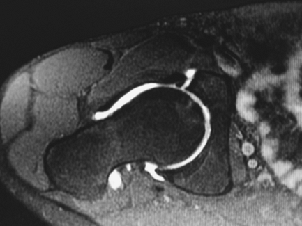
The addition of paramagnetic intravenous contrast agents
such as gadolinium to MRI increases the signal in vascular structures
around the hip. In the setting of avascular necrosis, this may help to
distinguish between areas of reparative and necrotic tissue.
Intravenous (IV) contrast may also help in identifying focal fluid
collections. After contrast administration, rim enhancement of a
nonvascularized abscess can be differentiated from diffusely enhancing
inflammatory tissue. MRI arthrography, consisting of the direct
installation of gadolinium into the hip joint, has proven valuable in
the diagnosis of labral and chondral pathology of the hip (Fig. 2-20).
Magnetic Resonance Imaging and Prosthetic Evaluation
Previously, large artifacts and noise prevented useful
magnetic resonance imaging of the total hip prosthesis. Recently, new
imaging protocols have allowed for less artifact and more accurate
depiction of soft tissue and bone around the prosthesis. One area where
this technology may prove particularly useful is in the early detection
and assessment of periprosthetic osteolysis. Preliminary data suggests
that metal suppression MRI techniques may be more sensitive and
specific than plain radiographs in determining the presence and volume
of periprosthetic osteolysis.
Nuclear Imaging
Nuclear imaging studies (bone scintigraphy) remain useful tools for detecting areas for abnormal metabolic activity
P.16
in bone. The bone scan is typically performed in three phases after administration of technetium 99:
 |
|
Figure 2-20 MRI arthrography of the hip demonstrating anterior labral tear.
|
 |
|
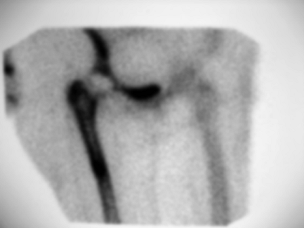
Figure 2-21
Tech 99 bone scan demonstrating symmetric uptake of tracer around the femoral component of a right total hip arthroplasty consistent with loosening of the prosthesis. |
-
Vascular phase: images performed at 2 to 5 seconds indicate areas of increased or decreased blood flow
-
Blood pool phase: images to determine areas of hyperemia (osteomyelitis)
-
Delayed phase: images to determine areas of increased or decreased tracer uptake
Bone scintigraphy may be useful in evaluating the
suspected loose or infected total hip prosthesis when other clinical
modalities (laboratory values, x-ray views) are equivocal. Although
this technique has high sensitivity, it also has poor specificity.
Increased tracer uptake can be seen surrounding a normal hip prosthesis
fo ≤24 months after surgery. A loose hip prosthesis will commonly show
abnormal tracer uptake at the trochanters, tip of the prosthesis, and
acetabulum (Fig. 2-21).
Although infection at the site of prosthesis will
generally show diffuse uptake, bone scintigraphy is not specific enough
to differentiate infection from loosening. The addition of
indium-111—labeled leukocyte scan that accumulates in regions of
infection by chemotaxis has been shown to improve both the sensitivity
and specificity of identifying periprosthetic infection, especially
when combined with technetium-99 bone scan. Because indium-111 may also
accumulate at the site of bone marrow distribution, the addition of a
sulphur colloid bone marrow scan may also aid in improving the
sensitivity and specificity. If abnormal uptake of white blood cells on
an indium scan is not matched by congruent uptake on a bone marrow
scan, the findings more likely correlate with infection.
Suggested Readings
Garvin KL, McKillip TM. History and physical examination. In Callaghan JJ, Rosenberg AG, Rubash HE. The Adult Hip. Philadelphia: Lippincott-Raven Publishers; 1998:315–332.
Greenspan A. Orthopaedic Imaging: A Practical Approach. Philadelphia: Lippincott Williams and Wilkins; 2004.