
performed annually in the United States for patients with disabling
knee pain or impairment of knee function and in whom conservative
treatment was not successful. A variety of implant designs are
available for total knee arthroplasty. Classification considers the
amount of constraint on the implant and the surgical approach taken to
the posterior cruciate ligament (i.e., sacrificed, retained, or
substituted). Implant selection for more or less constrained implants
is based on the patient’s needs, taking into consideration the function
of the knee ligaments, deformity, host bone quality, and any bone loss.
fix the implant to the host bone using cement and resurface the
femoral, tibial, and patellar components. Whenever possible, the least
constrained implants should be applied, because they are considered to
have the best longevity due to decreased loosening forces. Fully
constrained implants have been reported to have increased rates of
infection, tibial loosening, and wear.
the articulation between the patella and femoral intercondylar groove.
Between the medial and lateral tibial plateaus is the nonarticular
intercondylar region, which provides attachment sites for the anterior
and posterior cruciate ligaments, and the medial and lateral menisci.
The anterior and posterior cruciate ligaments are considered to be
extraarticular because they are enclosed by synovium. Within the
intercondylar region are two intercondylar eminences, or spines, medial
(anterior) and lateral (posterior); neither serve as attachment sites
for the cruciate ligaments.
posterior to the knee joint, and as a result, the posterior approach is
reserved for procedures involving those structures. The patella is the
largest sesamoid bone and functions to protect the knee joint, to
facilitate knee joint lubrication, and to increase the lever arm of the
knee extensor mechanism. Deep to the patella tendon is the fat pad. The
knee also contains the medial and lateral menisci; each is attached to
the tibia by the coronary ligament. The menisci increase joint
stability by increasing the joint concavity, act as shock absorbers to
more evenly distribute forces across the knee, contribute to joint
lubrication, and aid in knee rotation. The menisci structure is divided
into an avascular red zone (i.e., peripheral one third) and a vascular
white zone (i.e., inner third).
The ligaments on the medial side of the knee often merge with each
other, making identification of each layer difficult. The medial side
of the knee consists of three layers: outer, middle, and deep. The
outer, or most superficial, layer is the deep fascia of the thigh,
whose fibers enclose the muscles and tendons of the pes anserinus
before they insert into the tibia. The middle layer of the medial knee
is the superficial medial collateral ligament that extends from just
distal to the adductor tubercle to insert as a quadrangular ligament
approximately 6 cm below the joint line into the subcutaneous border of
the tibia. The superficial medial collateral ligament lies slightly
posterior to the knee axis of rotation. Proximal and anterior to the
insertion of the superficial medial ligament, a fibrous tissue band
extends from the middle layer to the medial side of the patella as the
medial patellofemoral ligament. The semimembranosus tendon continues
posteriorly across the popliteal fossa and inserts into the posterior
portion of the tibial medial condyle. The deep layer of the medial knee
consists of the joint capsule; the deep medial collateral ligament,
which extends from the medial epicondyle of the femur to the medial
meniscus; and the coronary ligament, which anchors the medial meniscus
to the tibia. Each of the three muscles that insert into the pes
anserinus on the anteromedial tibia—the sartorius (i.e., femoral
nerve), the semitendinosus (i.e., sciatic nerve), and the gracilis
(i.e., obturator nerve)—has a different nerve supply. Because all three
muscles originate from widely separated positions on the pelvis (i.e.,
the sartorius from the anterior superior iliac spine, the
semitendinosus from the ischial tuberosity, and the gracilis from the
inferior pubic ramus), they function in a powerful manner to stabilize
the pelvis on the leg, to flex the knee, and internally to rotate the
tibia.
the outer, middle, and deep. The outer layer consists of the deep
fascia of the thigh, the iliotibial band (which inserts into the area
of the lateral tibial condyle known as Gerdy’s tubercle), the biceps
femoris, and the lateral patellar retinaculum. The middle layer
consists of the superficial lateral collateral ligament and the lateral
inferior genicular vessels. The deep layer consists of the knee joint
capsule, the popliteus muscle and tendon, and the deep lateral
collateral ligament (which extends from the lateral femoral condyle to
the fibular head).
 |
|
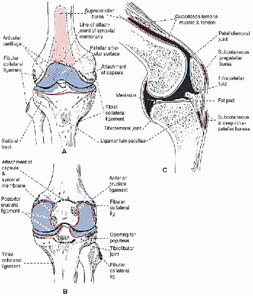
FIGURE 28-1.
The anatomy of the knee joint, showing the attachments of the capsule, synovial membrane, ligaments, and menisci: anterior view (A), posterior view (B), and sagittal section cut to one side of the midline (C). The attachment of the capsule is indicated with a dashed black line and that of the synovial membrane with a red line. Cavities filled with synovial fluid are shown in black in C. |
formed inferiorly by the gap between the two heads of the
gastrocnemius, by the semimembranosus and semitendinosus medially, and
by the biceps femoris laterally. Its inferior boundaries are the two
heads of the gastrocnemius.
nerve) runs lateral to the popliteal artery as it enters the popliteal
fossa, crosses the artery at the midpoint to run medial to it, and then
exits the fossa between the two heads of the gastrocnemius. The tibial
nerve supplies motor branches to the plantaris, gastrocnemius, soleus,
and popliteus muscles, and it has a single sensory branch, the sural
nerve. The common peroneal nerve diverges laterally to the medial side
of the biceps tendon and enters the peroneus longus muscle before
winding around the fibula. The common peroneal nerve divides into deep
and superficial peroneal nerves within peroneus longus muscle. The
popliteal artery divides into its terminal branches, the posterior
tibial, anterior tibial, and peroneal arteries, behind the
gastrocnemius.
its insertion. The popliteus functions to unlock the knee from its
fully extended screw-home position. This is accomplished
by
shifting the lateral femoral condyle behind the tibia and drawing the
lateral meniscus posteriorly, preventing it from being trapped between
the tibia and femur.
experience disabling knee pain, for those whose radiographs exhibit
significant joint degeneration, and those for whom nonoperative
treatment (e.g., oral medications, weight reduction and exercise
programs, assistive ambulatory devices) has failed. Candidates
considered for total knee arthroplasty must not be patients who would
be more appropriately treated by another surgical procedure such as
realignment osteotomy. Absolute
contraindications include a lack of a functioning extensor mechanism,
absence of neuromuscular control, active sepsis, a well-functioning
knee arthrodesis, or a neuropathic joint (controversial). Relative
contraindications include a history of knee sepsis or ipsilateral
osteomyelitis, significant peripheral vascular disease, or an extended
period of nonambulatory status. A patient with previous
tuberculosis arthritis can be successfully implanted with total knee
implants if she or he is given preoperative and postoperative
chemotherapy and the infection is not active.
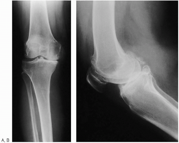 |
|
FIGURE 28-2. Anteroposterior standing (weight bearing) (A) and lateral (B) preoperative radiographs of the knee.
|
and a sunrise view of the affected knee are obtained. A long, standing,
anteroposterior radiograph showing the center of the femoral head, the
knee, and as much of the tibia as possible (preferably including the
ankle) can also be obtained. This type of radiograph is especially
useful in patients with suspected abnormal femoral or tibial geometry,
in which the mechanical axis may be difficult to determine. If long
x-ray films are not available, an anteroposterior radiograph (14
 17 inch x-ray film) of the entire femur permits similar calculations. To
determine the angle between the mechanical and anatomic axes, the
surgeon draws two lines to the center of the distal femur at the knee:
one from the center of the femoral head and the second from the center
of the femoral shaft, simulating the position of the intramedullary
alignment rod that will be used during surgery. The resultant
angle is usually 5 to 7 degrees. It may be less than 5 degrees in
patients who have a more valgus femoral neck (e.g., in patients with
previous total hip arthroplasty with a femoral component in valgus or
in patients with coxa valga). Less commonly, the angle between the
mechanical and anatomic axis is greater than 7 degrees (e.g., in
patients with significant coxa vara or a broad pelvis with long femoral
necks).
alignment guide to help reestablish the anatomic axis. Typically, the
surgeon dials in the desired distal femoral resection based on the
intramedullary alignment rod placed into the center of the femur. As a
general rule, the implant should be positioned such that, when the
patient is standing, the joint is parallel to the ground, precluding
shear forces across the joint. The distal
femoral cut should be planned for the predetermined angle (usually 5 to
7 degrees) to be perpendicular to the anatomic axis that will then be
perpendicular to the mechanical axis, thereby reestablishing normal
alignment. A special case is the patient
with large thigh muscle or soft tissue; in this case, less valgus
(e.g., 5 degrees) should be used to prevent the thighs from rubbing
together during gait. In patients with marked valgus or varus
deformities, it is often easier to balance the total knee if less
correction is planned (i.e., 7-degree cut for patients with valgus knee
or a 5-degree cut for patients with marked varus knees).
of the ankle are readily visualized during surgery, no preoperative
calculations for the tibia are necessary. If an extramedullary
tibia-cutting guide is used, it is applied directly to these key
locations, and the proximal tibia is cut perpendicular to this line or
with a slight (3- to 5-degree) posterior slope.
 |
|
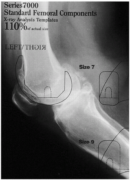
FIGURE 28-3. A preoperative template in the lateral projection is used to estimate the implant’s size.
|
 |
|
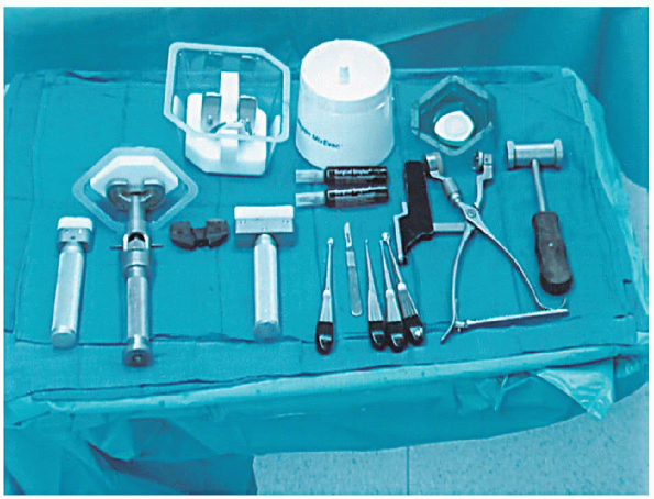
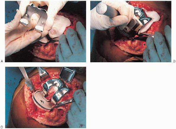
FIGURE 28-4. General instruments. Top: Femoral component, polymethylmethacrylate and mixing bowl, and the patella component. Bottom:
Tibial component impactor, tibial component on a handle, femoral impactor, curettes and no. 10 blade scalpel, patella clamp, and mallet. |
Preoperative examination should note the knee range of motion and
ligamentous stability. If these are altered, the surgeon may need to
use special implants or anticipate alterations in surgical technique to
accommodate these problems. Hip range of motion
is also important, because if the hip does not adequately flex, there
may be problems in achieving the desired knee flexion.
choosing a specific make and model, the surgeon should become familiar
with its brand-specific surgical techniques. General instruments are
shown in Figure 28-4. The following generic remarks are intended to review surgical techniques common to many total knee systems.
after anesthesia has been administered. A tourniquet is applied to the
thigh. The patient’s foot is moved to the end of the operating table to
give the surgeon easy access from the side and the end of the table. The
operative limb needs to be fixed in the flexed position during the
operation; this is facilitated by using a leg-holding device or sandbag
secured on the table at the level of the knee crease in the popliteal
fossae. Bulky drapes should avoided on the distal tibia, ankle, and
foot, because they can interfere with locating the center of the ankle
and can displace the extramedullary tibial cutting guide and result in
inaccurate cuts.
is placed over the foot and a stockinet placed from the foot to the
middle of the thigh. The anterior aspect of the knee is exposed and
draped with a clear, sterile, adhesive dressing. A small section (2
inches wide) of sterile, clear, adhesive dressing is wrapped around the
ankle at the level of the malleoli.
arthroplasty patients is higher among those who have previously
undergone knee surgery. In these patients, the blood supply to the
anterior knee skin is tenuous because of the lack of an underlying
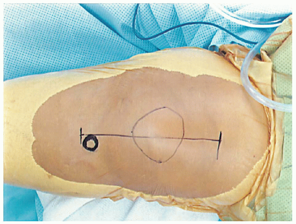
muscular pedicle. The knee replacement surgical
incision should incorporate previous incisions; if possible, the new
incision should intersect the prior incision by an angle of at least a
60 degrees. When a parallel incision is required, the skin bridge
should be at least 7 cm. Key anatomic landmarks are the patella and the
tibial tubercle, both of which are easily palpated (Fig. 28-5).
patients with no previous knee surgery, an anterior midline skin
incision is followed by an anteromedial capsulotomy and a longitudinal
incision in the quadriceps tendon.

Alternative approaches include the subvastus or midvastus approach;
they generally are used in patients who are not obese and exhibit
minimal deformity, good preoperative range of motion (>90 degrees),
and lack a significant flexion contracture (<15 degrees). The
subvastus approach (i.e., Southern approach) and midvastus approach (in
which the vastus medialis is reflected laterally or split in its
midportion, with the superior portion reflected laterally) preserve the
extensor mechanism, theoretically resulting in faster rehabilitation
and preservation of the blood supply to the patella. In cases with
marked valgus deformity, an anterolateral capsulotomy is another
alternative, although difficulties in everting the patella may be
encountered.
 |
|
FIGURE 28-5. Key anatomic landmarks for the incision are the tibial tubercle and patella
|
 |
|
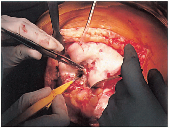
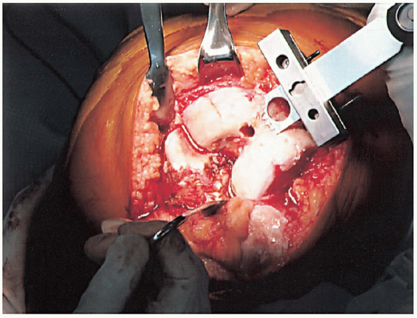
FIGURE 28-6. Removal of the anterior cruciate ligaments and the soft tissue on the anterior distal femur to expose the distal femur.
|
extending approximately 2 to 4 cm above the superior pole of the
patella to just medial of the tibial tubercle, a standard medial
parapatellar arthrotomy is performed. Lateral retinacular release can
be performed—because it has been planned or because marked difficulty
everting the patella is encountered. The patella is everted, the foot
externally rotated, and the knee flexed to more than 90 degrees. The
anterior cruciate ligaments (Fig. 28-6) and the soft tissue on the anterior distal femur are removed to expose the bone for later referencing for the femoral cut. If
significant preoperative soft tissue contracture exists, a preliminary
soft tissue release should be performed to aid exposure. If the knee
has severe fixed varus or valgus deformity, releases will be required.
preparation of the femur and tibia, they are typically prepared
independently. Either the tibia or femur can be prepared first; most
surgeons prepare the femur first, because resection of the posterior
femoral condyles permits greater exposure of the upper tibia and
facilitates its preparation. Fine tuning of minor varus or valgus
imbalances should be performed after all bone cuts with provisional
(trial) components are in place.
broken down into three major steps: femoral, tibial, and patella
preparation. Alignment of components in the coronal, sagittal, and
transverse planes is critical for a long-term successful clinical
outcome, because it has been demonstrated
that malalignment is associated with an increased incidence of component loosening.
 |
|
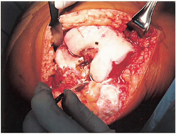
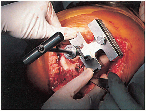
FIGURE 28-7.
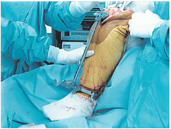
With the knee flexed, a site 1 cm anterior to the origin of the posterior cruciate ligament is identified as the insertion point for the femoral intramedullary alignment rod. |
of six steps: (1) drilling a hole in the distal femur and inserting the
intramedullary femoral alignment guide; (2) cutting the distal femur;
(3) measuring the anteroposterior dimension of the distal femur; (4)
measuring to ensure no anterior femoral notching; (5) making the final
anterior, posterior, and chamfer femoral cuts; and (6) preparing the
trochlear groove or intercondylar notch, or both, for posteriorly
stabilized substituting of femoral components.
of the posterior cruciate ligament is identified as the insertion point
for the femoral intramedullary alignment rod (Fig. 28-7).
This places the drill hole just anterior to the distal femur
intercondylar notch. This line must be parallel to the femoral shaft in
both the anteroposterior and lateral projections. The
surgeon should be certain that only the cancellous bone of the distal
femur is drilled to avoid potential femoral perforation. For this
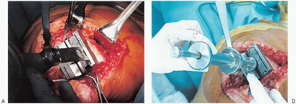
purpose, a blunt-tipped, canal-finding tool (Fig. 28-8A) or reamer (Fig. 28-8B) is used, because the hollow diaphysis provides little resistance. After the canal is thoroughly suctioned (Fig. 28-9A), a slotted or hollow intramedullary rod is inserted that prevents intramedullary fat pressurization (Fig. 28-9B).
 |
|
FIGURE 28-8. The intramedullary canal of the distal femur is opened using a blunt-tipped canal-finding tool (A) or a reamer (B).
|
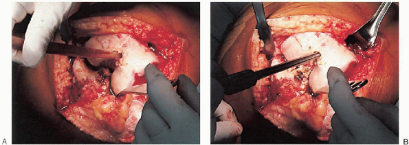 |
|
FIGURE 28-9. After suctioning of the canal (A), a slotted or hollow intramedullary rod is inserted to prevent intramedullary fat pressurization (B).
|
multiple lengths. The standard rod typically extends to the proximal
femur and provides the most accurate reproduction of the anatomic axis.
If the femoral anatomy is altered (by previous
fracture malunion or in the case of a femur with a long-stem total hip
femoral component), a shorter rod should be used. In the rare
case in which there is no access to the medullary canal (e.g., a
retained femoral nail), an extramedullary alignment system should be
used. Whenever possible, the longest intramedullary rod should be used
to most accurately replicate the anatomic axis.
into the femur, it may be necessary to control rotation of the distal
cutting block. In many systems, anatomic external rotation is built
into the sizing block; in others, it is built into the implant.
Rotational alignment must be correct for subsequent cuts, proper
component orientation, and proper patella tracking. Proper
orientation is along a transverse line drawn between the medial and
lateral epicondyles; this line is often parallel to the posterior
femoral condyles if no bone loss has occurred.
femoral intramedullary alignment rod and set to the desired angular cut
to the anatomic femoral axis (Fig. 28-10).
Typically, this block is pinned into place, and the distal femoral
resection is performed with an oscillating saw through a slotted
cutting block (Fig. 28-11). The amount of bone removed in routine cases is identical to the amount that will be replaced by the femoral component. Correct bone resection thickness is accomplished only if the distal femoral block is flush against the distal femoral condyles.
In cases of marked flexion contracture, the surgeon may wish to resect
more femoral bone at the outset. After distal femoral resection, the
pinholes are marked with methylene blue to facilitate repeat pin
placement if further distal femoral resection is desired after trial
components have been introduced and range-of-motion testing performed.
the distal femur is crucial for ensuring that the correct size of
component is used; this can be accomplished using anterior or posterior
referencing instruments. In anterior referencing, a preliminary
anterior femoral cut is made flush with the anterior cortex of the
femur. This should reduce the possibility of notching the anterior
surface of the femoral cortex. In posterior referencing, the distance
from the posterior condyles to the anterior cortex is determined. There
is no consensus about which referencing technique is better. Proponents
of anterior referencing cite the lack of femoral notching as an
advantage and accept the possibility of a flexion-extension mismatch
(i.e., more looseness in flexion) if between sizes. Proponents of
posterior referencing also site the lack of femoral notching, but
acknowledge it is at greater risk of occurrence than anterior
referencing. They also site as an advantage a balanced
flexion-extension gap and accept the possibility of overstuffing the
patellofemoral joint if a mismatch occurs between sizes. The femoral
anteroposterior measuring guide should be placed flat against the cut
distal femur; hyperflexion of the knee often assists in positioning the
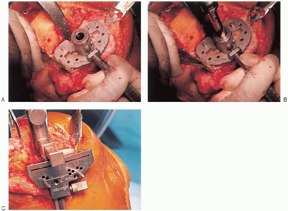
feet of the guide against the posterior condyles (Fig. 28-12).
Uncommonly, the proximal tibia may have to be resected first to
facilitate proper positioning of the sizing guide. With the feet of the
guide on the cartilage of the posterior
condyles,
a mobile gauge is moved until it rests on the anterior femoral surface.
The guide displays the proper size of the femoral implant to be used. When
using anterior referencing, if femur size falls between two standard
implant sizes, the surgeon should use the smaller implant to avoid
overstuffing the flexion gap; when using posterior referencing, it is
better to use the larger implant to avoid notching the anterior surface
of the femoral cortex.
 |
|
FIGURE 28-10.
The distal femoral cutting block is attached to the femoral intramedullary alignment rod. The block is set to the planned angular cut relative to the anatomic femoral axis. |
 |
|
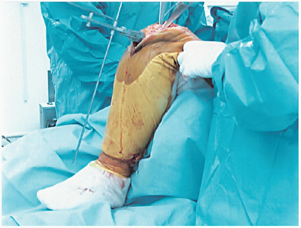
FIGURE 28-11.
With the block pinned into position, the distal femoral resection is performed with an oscillating saw through the slotted cutting block. |
 |
|
FIGURE 28-12. A and B:
The femoral anteroposterior measuring guide is positioned flat against the cut distal femur with the feet of the guide against the posterior condyles. Holes for the anterior, posterior, and chamfer cuts are drilled. |
or posterior condyles first, followed by the chamfers; performing cuts
in this sequence ensures that the guide will maintain optimal stability
during bone resection. Preparation of the distal femur concludes with
placement of the appropriate trochlear groove or intercondylar notch
resection guide and cutting tools (set the guide in the desired final
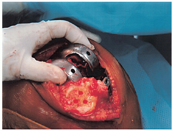
mediolateral position of the femoral component) (Fig. 28-16). The femoral component should be placed as far laterally as possible to facilitate patella tracking (Fig. 28-17).
 |
|
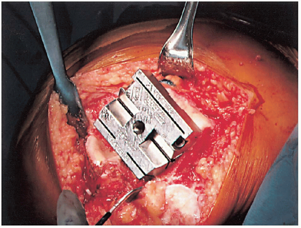
FIGURE 28-13. The femoral cutting block is positioned on the distal femur and secured.
|
alignment instrumentation. To optimize exposure of the proximal tibia,
it can be subluxated anteriorly using an appropriate posterior
retractor. The posterior cruciate ligament can be removed or recessed,
if desired at this time.
and the distal aspect of the guide centered over the middle third of
the ankle. For use of an intramedullary alignment guide, a pilot
hole is drilled (centered on the proximal tibia) to gain access to the medullary canal (Fig. 28-20). It
is important to center the guide over the proximal tibia in the
mediolateral direction so that the guide is parallel to the mechanical
axis of the tibia. A similar cutting block, used with
extramedullary alignment guides, is typically used to set the desired
proximal tibial resection. The guide should be aligned to allow for 0
to 5 degrees of posterior slope and neutral varus-valgus alignment, and
it should be set to remove the necessary amount of proximal tibia to be
resurfaced (Fig. 28-21). Most systems include a
tibial depth resection gauge to help determine the amount of bone to be
resected. The cutting block is secured with pins and the proximal tibia
resected with an oscillating saw (Fig. 28-22).
In many cases, the tibial bone resection is below a tibial bone defect.
If bone defects are excessive, alternative implants or augmentation
wedges may be needed.
 |
|
FIGURE 28-14. Guides should be used to avoid notching the anterior femoral cortex by the anterior femoral cut.
|
 |
|
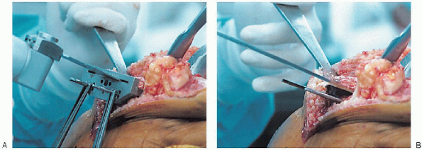
FIGURE 28-15. A:
Cutting the anterior condyles is followed by cutting the posterior condyles and then the chamfers; the sequence supports optimal stability during bone resection. B: After the cuts are completed, the cutting block is removed with its extractor. |
 |
|
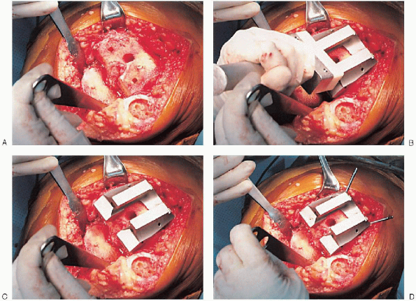
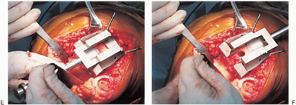
FIGURE 28-16. A to F:
Preparation of the distal femur. Placement of the appropriate trochlear groove and intercondylar notch resection guide. Removal of bone is accomplished with the appropriate guides and cutting tools. Notice the final mediolateral position of the femoral component. |
 |
|
FIGURE 28-16. A to F: Continued.
|
 |
|
FIGURE 28-17. Placement of the femoral component as far lateral as possible to facilitate patella tracking.
|
 |
|
FIGURE 28-18. Tibial cut using extramedullary alignment instrumentation.
|
 |
|
FIGURE 28-19.
Placement of slotted cutting guide on the bone in the center of the proximal tibia. The distal aspect of the guide is centered over the middle third of the ankle. |
tibial-articulating surface by using trial components with plastic
inserts in a range of sizes. After appropriate
implant size is determined, the keel guide is placed and rotated so
that it is centered over the middle third of the tibial tubercle, and
the keel is punched using appropriate instrumentation (Fig. 28-23).
 |
|
FIGURE 28-20. A to C:
When using an intramedullary alignment guide, a pilot hole is drilled (centered on the proximal tibia) to gain access to the medullary canal. |
next. The goal to obtain a balance of soft tissues so that stresses are
evenly distributed throughout the components and to ensure
a
full and smooth arc of motion. With all trial components in place, the
range of motion and ligament stability are assessed. The distal femur
and proximal tibia should have been prepared so that a good fit of
components exists along with a correct mechanical axis. The thickest
tibial articulating surface should be used that still allows full
flexion and full extension. Soft tissue tension in flexion and
extension should be examined. Appropriate soft tissue releases are
necessary if the medial or lateral side of the knee is
disproportionately tight or if the flexion or extension gaps are not
balanced. The surgeon should remove any osteophytes that can
artificially tent or tighten a ligament and interfere with soft tissue
balancing.
 |
|
FIGURE 28-21. Alignment of the tibia cutting block should be checked with an extramedullary rod placed off of the tibial cutting block.
|
 |
|
FIGURE 28-22. A and B:
A tibial depth resection gauge is used to help determine the amount of bone to be resected. The cutting block is secured with pins and the proximal tibia resected with an oscillating saw. |
 |
|
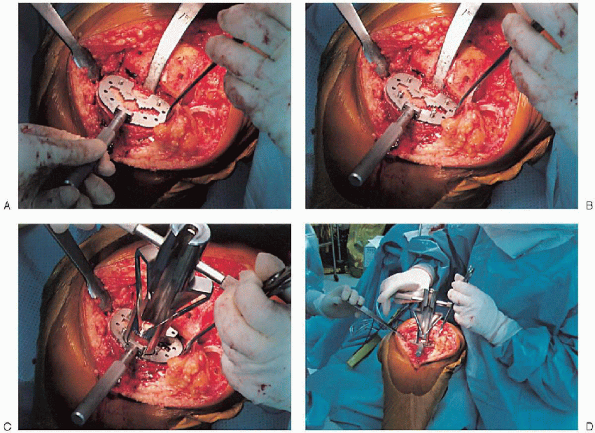
FIGURE 28-23. A to D:
The keel guide is placed when the appropriate implant size is determined and rotated so that it is centered over the middle third of the tibial tubercle. The keel is punched using appropriate instrumentation. |
varus and valgus stresses are applied with the knee in full extension
and in slight flexion, because an intact posterior capsule can give a
false impression of collateral stability in complete extension.
If one side is tighter than the other, a soft tissue release is
performed. These releases should be conducted in small stages (i.e.,
with partial release of one specific contracted element at a time),
with reassessment of ligament balance after each release. Possible
attendant deformities and their corresponding releases are summarized
in the following sections.
soft tissue releases are necessary with the trial components in place,
the surgeon should first elevate the superficial medial collateral
ligament subperiosteally from the tibia, followed by the posteromedial
corner of the capsule subperiosteally, the pes anserinus tendons
subperiosteally, and the posterior cruciate ligament, if necessary, to
achieve ligament balance.
tissue contracture on the lateral side of the knee. Frequently, these
patients require a lateral patellar retinacular release. Although
no consensus exists regarding proper sequence of releases, a sound
approach is to sequentially release the popliteus tendon, posterior
cruciate ligament, posterolateral capsule, iliotibial band (by
Z-lengthening, cut on a diagonal or perforated with multiple small stab
incisions through the superior portion of the medial parapatellar skin
incision or through a separate incision on the lateral side of the
distal femur), and lateral collateral ligament off of the distal
femoral condyle. In cases with marked deformity, it may also be
necessary to release the biceps femoris tendon by Z-lengthening through
a separate incision because the tendon transverses with the peroneal
nerve at the knee.
 |
|
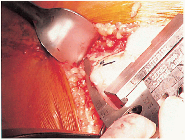
FIGURE 28-24. A to G: Preparation of the patella using an inset design. A caliper is used to measure the patella thickness.
|
can usually be corrected by removing posterior osteophytes or resecting
more of the distal femur. If these steps fail to achieve full
extension, a subperiosteal release of the posterior cruciate ligament
and posterior capsule from the femur should be performed. If full
extension is still not achieved, the origin of the gastrocnemius
tendons should be elevated from the posterior part of the femur.
When resecting more distal femur, the surgeon should beware not to
remove so much bone as to cause damage to the femoral attachments of
the collateral ligament.
or resurfacing design. A caliper is used to measure the patella
thickness. Typically, the exact amount of bone to be resurfaced is
removed. As a general rule, the patella should be made no thinner than 12 mm to avoid the risk of later patella fracture. The patella should be sized, and for inset designed patellar components, the surgeon should ream to
remove the precise amount of bone to be resurfaced. When resurfacing
the patella, it can be secured with sharp towel clips or
manufacturer-supplied holding tools and cut flat with a saw. After
cutting peg holes are drilled for the component, a trial component is
placed and the thickness checked.
 |
|
FIGURE 28-24. Continued.
|
knee flexion is corrected by lateral retinacular release performed from
inside the knee joint. If lateral retinacular release is performed,
care must be taken to avoid the superolateral geniculate artery. A
standard technique is to perform the release distal to the superior
lateral geniculate artery and test tracking again; if the patella still
does not track correctly, the release should be carried more
proximally. If a tourniquet is used, it should be
released before closure to ensure that the vessel, if it is transected,
is ligated; otherwise, a large postoperative hemarthrosis can occur.
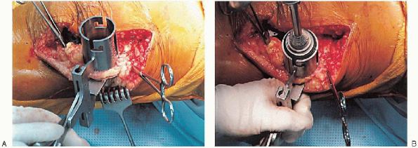
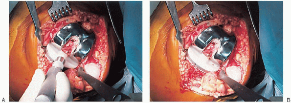
cement mixing or be done in stages. If one-step mixing is used, the
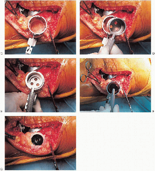
order of implantation is the tibia (Fig. 28-25), followed by the femoral component (Fig. 28-26), followed by the patella (Fig. 28-27). A trial plastic tibial insert (Fig. 28-28)
is typically used during curing of the cement to permit later stability
testing and to facilitate removal of any cement from the posterior
aspect of the knee. Excess cement is removed during curing. After the
cement hardens, the wound is checked for extruded cement, which should
be removed. The final high-molecular-weight polyethylene tibial insert
is locked into position on a clean and dry tibial base plate (Fig. 28-29).
 |
|
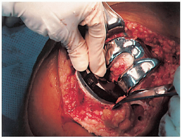
FIGURE 28-25. A to D: Tibial implantation.
|
whether the tourniquet should be deflated to establish hemostasis. If a
lateral retinacular release is performed, the tourniquet should be
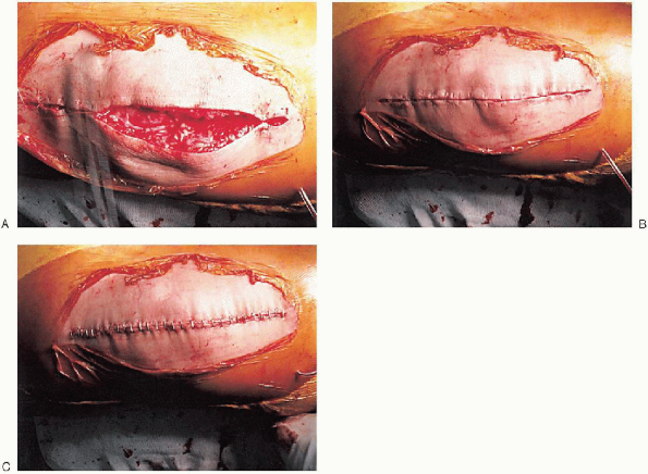
deflated. A single drain is usually placed and the capsular repair performed (Fig. 28-30);
range of motion and patella tracking should be checked again to ensure
proper alignment and tracking. After skin closure, the incision is
covered with a sterile dressing and wrapped with an elastic bandage
from the toes to the groin. The patient is transferred from
the
operating room to the postanesthesia recovery room. In the recovery
room, some surgeons elect to begin postoperative rehabilitation by
placing the leg in a continuous passive motion (CPM) machine; others
immobilize the knee to facilitate comfort and wound healing.
 |
|
FIGURE 28-26. A to C: Femoral implantation.
|
 |
|
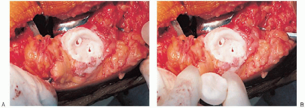
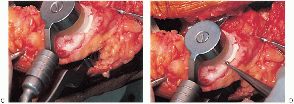
FIGURE 28-27. A to D: Patellar implantation.
|
 |
|
FIGURE 28-27. Continued.
|
 |
|
FIGURE 28-28.
A trial plastic tibial insert is used during curing of the cement to permit later stability testing and to facilitate removal of any cement from the posterior aspect of the knee. |
 |
|
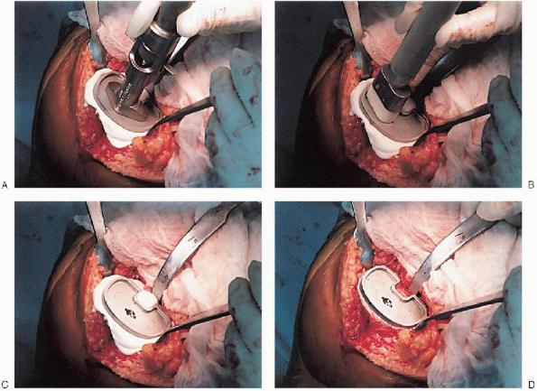
FIGURE 28-29. A and B:
After the cement has hardened and any extruded cement has been removed, the final high-molecular-weight polyethylene tibial insert is locked into position on a clean and dry tibial base plate. |
 |
|
FIGURE 28-30. A to C: Closure. A single drain is placed before the capsular repair.
|
to 5 days and then sent home or transported to a rehabilitation
facility. All patients receive deep venous thrombosis prophylaxis
(e.g., mechanical, pharmacologic) and begin physical therapy on the day
after surgery. Prophylactic antibiotics are used until the drains are
removed, usually 24 to 36 hours after surgery. Drains left in place for
more than 48 hours have been associated with increased risk of
infection.
gait training are emphasized. Patients may use a knee immobilizer for
comfort; some use CPM as part of their rehabilitation protocol. The
effect of CPM on outcomes after total knee arthroplasty remains
equivocal. Potential advantages of CPM include improved early range of
motion, decreased incidence of deep vein thrombosis and pulmonary
embolus, faster pain relief, and shorter duration of hospitalization.
Potential disadvantages of CPM are increased wound complications and a
lack of long-term benefits. To avoid wound problems with CPM, it is
recommended to use a rate of one cycle per minute with 40 degrees of
maximum flexion for the first 3 days. Surgical staples are removed on
about postoperative day 14.
Many factors influence the final range of knee motion after total knee
arthroplasty. Most patients achieve a knee range of motion of
approximately 110 degrees of flexion. Poor knee flexion (<90
degrees) may be improved by closed manipulation under spinal
anesthesia. This procedure should not be
performed after 12 weeks from surgery because it holds an increased
risk of periprosthetic fracture. Most patients are in a
structured physical therapy program for up to 3 months after surgery.
After the patient has achieved the desired range of motion
and ambulates without aid, she or he is typically followed on a yearly basis.
 |
|
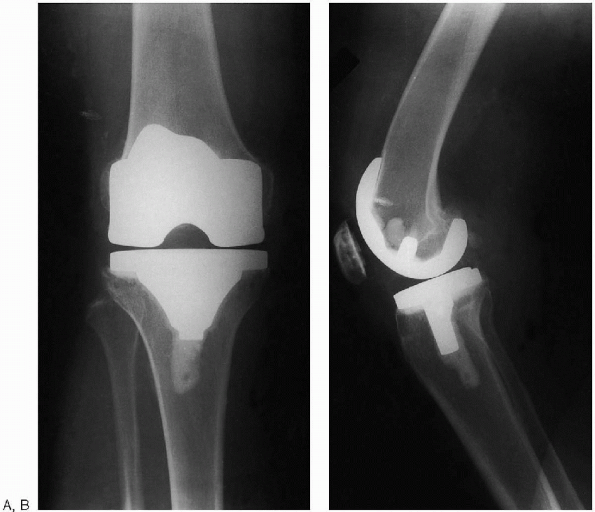
FIGURE 28-31. Postoperative anteroposterior (A) and lateral (B) radiographs of total knee arthroplasty.
|
Knee replacement surgery for osteoarthritis: effectiveness, practice
variations, indications and possible determinants of utilization. Rheumatology (Oxford) 1999;38:73-83.