
They commonly result from contact and noncontact types of sporting
activities. These injuries often result in instability of the knee and
may prevent individuals from participating in cutting- and
pivoting-type sporting activities. ACL injuries may make the individual
susceptible to additional injuries of the knee, such as meniscal tears
and osteochondral defects, and to premature arthrosis of the knee.
Reconstruction of the ACL is recommended for individuals who have
symptomatic instability during sports or activities of daily living.
The success rate has been reported to be more than 95% in terms of
patient satisfaction, with most individuals returning to their
preinjury level of activity.
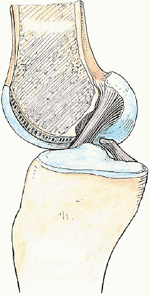
aspect of the lateral femoral condyle, crosses anteriorly and medially
to the posterior cruciate ligament (PCL), and inserts widely on the
anteromedial tibial plateau between the tibial eminences. The average
length is 31 to 38 mm, and the average width is 11 mm. It is an
intraarticular and intrasynovial ligament, which consists of an
anteromedial bundle (i.e., taut in flexion and lax in extension) and a
posterolateral bundle (i.e., taut in extension and lax in flexion). The
ACL acts as the primary restraint to anterior translation of the knee (Fig. 26-1).
injury and most commonly results in instability of the knee. For an
active, healthy person who wishes to return to some level of athletic
activity, reconstruction of the ACL is recommended. A minimum range of
motion (ROM) of 5 to 90 degrees (with minimal residual inflammation) is
usually desired and should be achieved before surgical intervention.
which should always be compared with the contralateral knee, are
usually diagnostic of an ACL injury. Possible concomitant injuries,
such as those of the meniscus, medial collateral ligament,
posterolateral corner, and PCL, should also be ascertained during the
examination.
merchant views of the knee, are necessary to rule out any fractures,
degenerative changes, and malalignment. Magnetic resonance imaging may
be helpful to rule out other possible associated injuries, especially
meniscal tears, and to confirm an ACL injury.
 |
|
FIGURE 26-1. Anterior cruciate ligament, medial view.
|
 |
|
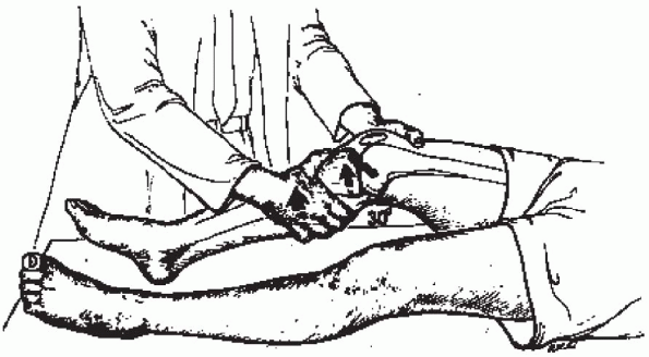
FIGURE 26-2.
The Lachman test is an anterior drawer test with the knee in 30 degrees of flexion. It tests anterior cruciate ligament integrity, with an emphasis on the posterolateral bundle. Reprinted from Tria AJ, Jr, Hosea TM. Diagnosis of knee ligament injuries. In: WN Scott (ed.), Ligament and extensor mechanism injuries of the knee: diagnosis and treatment. St. Louis: Mosby Year-Book, p. 94. © 1991, Mosby Year-Book, with permission from Elsevier. |
 |
|
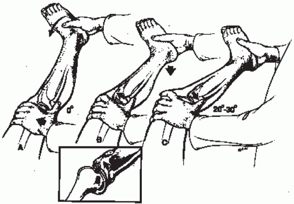
FIGURE 26-3.
The pivot shift of Galway and MacIntosh begins with knee in full extension, with internal rotation of tibia and valgus stress. The thumb subluxates the tibia forward, and a “clunk” of reduction is felt in the first 20 to 30 degrees of flexion, which correlates with anterior cruciate ligament disruption. Reprinted from Tria AJ, Jr, Hosea TM. Diagnosis of knee ligament injuries. In: WN Scott (ed.), Ligament and extensor mechanism injuries of the knee: diagnosis and treatment. St. Louis: Mosby Year-Book, p. 95. © 1991, Mosby Year-Book, with permission from Elsevier. |
 |
|
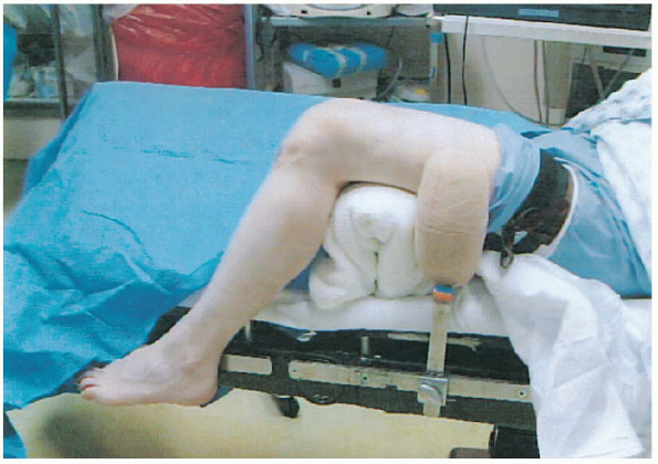
FIGURE 26-4. Position of the patient.
|
scope, camera, and hand and motorized instruments. ArthroWands
(ArthroCare, Sunnyvale, CA) may also be helpful. The Arthrex (Naples,
FL) transtibial ACL reconstruction system is used for instrumentation
throughout the illustrated procedure in this chapter. The following is
a list of necessary equipment, most of which is included in the system:
-
Oscillating saw
-
Adapteur drill guide C-ring with the target PCL-oriented marking hook
-
2.4-mm drill tip guide pins
-
Cannulated headed reamers (usually 10 mm)
-
Transtibial femoral ACL drill guide (usually 7-mm-offset tip)
-
Extra-long 2.4-mm guide pin with suture eye (Beathtype guide pin)
-
Sizing block
-
Workstation for the bone-patella tendon-bone graft
-
Cannulated, titanium interference screws
-
Tunnel notcher
-
2-mm pin lock guide pin
-
Pin lock cannulated screwdriver set
 |
|
FIGURE 26-5. Placement of the incision.
|
The procedure can be done under general or regional anesthesia. The
appropriate extremity is then examined under anesthesia, and the
findings recorded in the operative report. A tourniquet is applied high
on the upper thigh. If necessary, the knee is shaved. As is done for
routine knee arthroscopy, a removable post is placed adjacent to the
thigh, or the extremity is placed in a leg holder (Fig. 26-4).
The entire extremity is prepared up to the tourniquet and then
sterilely draped. A preoperative antibiotic (usually a first-generation
cephalosporin such as intravenous piggyback administration of 1 g of
cefazolin) is given before any incision is made.
reconstruction a with bone-patella tendon-bone autograft is
illustrated. In clear instances of an ACL rupture, the graft is
harvested first. If there is any doubt about the diagnosis, diagnostic
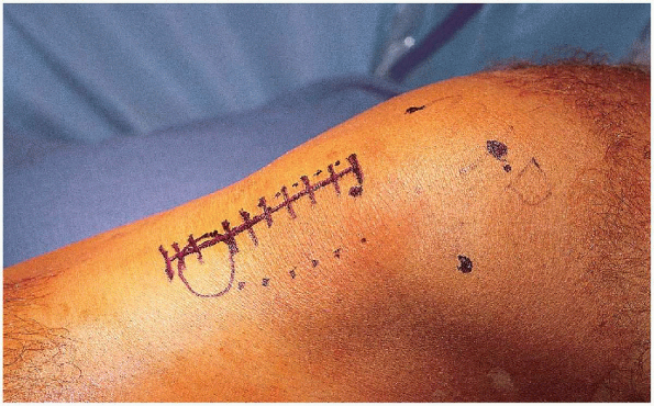
arthroscopy may be performed initially. Landmarks are drawn out with an
indelible surgical marker: the four borders of the patella, the tibial
tubercle, and the patella tendon. The incision is straight and just
medial to the tubercle, extending from the inferior border of the
patella to 2 cm distal to the tubercle (Fig. 26-5). Before the
incision is made, an Esmarch bandage is used as a tourniquet to
exsanguinate the extremity. With the knee flexed, the tourniquet is
inflated to approximately 300 mm Hg (approximately 150 mm Hg above the
systolic blood pressure).
 |
|
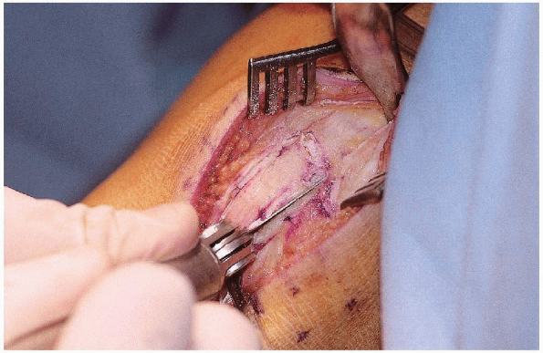
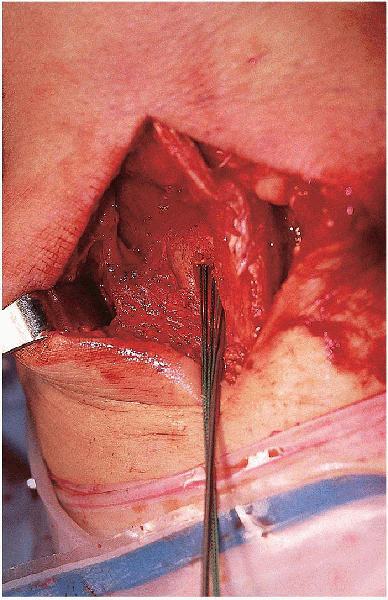
FIGURE 26-6. The patella tendon is cut in the middle 10 cm.
|
the knee at 30 to 45 degrees of flexion, the incision is carried though
skin and subcutaneous tissue down to the level of the paratenon.
Hemostasis is achieved with Bovie cautery. The paratenon is sharply
incised on the patella tendon and then completely incised as far
proximally (up to the middle patella) and distally (2 to 3 cm distal to
the tubercle) with Metzenbaum scissors. The edges of the tendon are
identified, and the width of the tendon is measured. The middle 10 cm
of the tendon is marked along the tendon (Fig. 26-6).
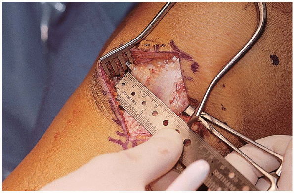
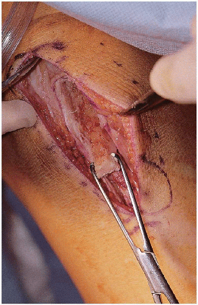
With a 10-mm-wide, parallel, double-blade scalpel, the tendon is
completely incised parallel along its fibers in the middle portion of
the tendon, extending from the distal pole of the patella to the tibial
tubercle (Fig. 26-7). A ruler is used to mark a
length of 25 mm distal to the insertion of the tendon on the tubercle.
Keeping the same 10 mm width of the incised tendon, an outline of the
osteotomy cut (10
 25 mm)
is made with a scalpel. An oscillating saw with a 7-mm-deep stop blade
(Arthrex) is used to cut the bone plug from the tibia in a rectangular
fashion (Fig. 26-8). A 0.25-inch, curved osteotome is used to carefully lift the bone plug out on each side (Fig. 26-9). Care should be taken not to lift it from the distal end because the bone plug may fracture from levering. The tibial plug is put back in its place as attention is directed toward the patella bone plug. A graft-harvesting patella retractor makes exposure of the entire patella easier.
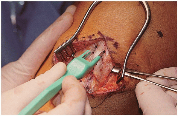
A ruler is used to mark a length of 20 cm proximal to the origin of the
patella tendon in the middle patella. Keeping the same 10 mm width of
the incised tendon, an outline of the osteotomy cut (10
20 mm) is made with a scalpel. Theoscillating saw is again used, and the bone plug from the patella is
cut in a triangular fashion—which is done to minimize the potential
stress riser left in the patella after harvesting—by angling the saw
blade 45 degrees to the cortex on each side and on the proximal
cross-cut end. (Fig. 26-10). A
0.25-inch, curved osteotome is used to carefully lift the bone plug on
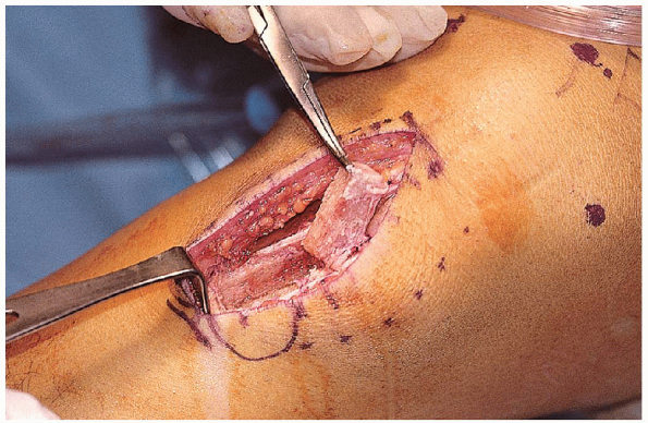
each side in a similar fashion to the tibial bone plug. The graft is
then clamped at each end and carefully dissected free from its
remaining soft tissue attachments (Fig. 26-11).
The graft is then carefully taken to a separate table for preparation.
The tourniquet may be let down at this point after harvesting, unless
intraarticular bleeding impedes optimal arthroscopic visualization.
 |
|
FIGURE 26-7. The patella tendon is cut using a 10-mm, doubleblade scalpel.
|
excess soft tissue and fat pad are carefully removed from the graft
with Metzenbaum scissors. The length of the tendinous portion of the
graft is measured and recorded (in this case, 45 mm long), because this
determines the angle at which the Adapteur drill guide C-ring is set
and minimizes graft-tunnel mismatch. The length of each bone plug is
also measured, verified, and recorded. We usually use the patella bone
plug (10
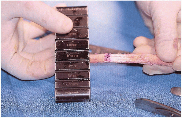
20 mm) in the femoral tunnel and the tibial bone plug (10 25 mm) in the tibial tunnel. The bone plugs are then shaped and contoured with a bone cutter, a small rongeur, and a 10 10 mm crimper. The bone fragments that are removed are saved for later bone grafting of the patella. Thebone plugs should be trimmed until the plug can be fit easily into the
10-mm sizing block (Arthrex) but not into the 9-mm sizing block (Fig. 26-12).
If this step is not done adequately, the graft will not fit into the
tunnels created. The cancellous side of the tendon is labeled with an
indelible marker at the tendo-osseus junction at the patella bone plug
end (i.e., the bone plug to be inserted into the femoral tunnel). The
graft is then placed on the graft
workstation (Arthrex) (Fig. 26-13).
Two holes spaced 5 mm apart are drilled with a 1.5-mm drill bit in the
patella bone plug in an anterior-to-posterior, cancellous-to-cortical
direction. Two holes spaced 5 mm apart are also drilled with a 1.5-mm
drill bit in the tibial bone plug perpendicular to each other: one in a
side-side direction proximally and one in an anterior-to-posterior,
cancellous-to-cortical direction distally. The no. 5 Ethibond (Ethicon,
Inc., Somerville, NJ) sutures are then passed with a free, straight
needle into each of the holes drilled. The sutures are clamped at each
end and then set aside in a moist lap pad (Fig. 26-14).
 |
|
FIGURE 26-8. A to C: An oscillating saw is used to cut a tibial bone plug.
|
 |
|
FIGURE 26-9. Procurement of the tibial bone plug.
|
 |
|
FIGURE 26-10. An oscillating saw is used to cut a patella bone plug.
|
 |
|
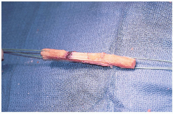
FIGURE 26-11. Free bone-patella tendon-bone autograft.
|
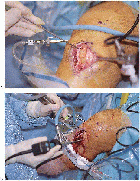
inferolateral portal is established through the operative incision just
adjacent to the patella tendon. The arthroscope is inserted through
this portal, and inflow is set at a level above the systolic blood
pressure. A superomedial portal is made for outflow, which is placed to
gravity. Diagnostic arthroscopy is then performed, evaluating the
suprapatellar pouch, patellofemoral joint, medial compartment,
intercondylar notch, and lateral compartment.
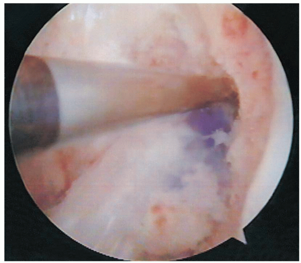
 Any chondral injuries or chondromalacia should be documented (Fig. 26-15).
An inferomedial portal is established through the operative incision as
a working portal. Both menisci should be carefully examined and probed
for any tears. Unstable meniscal tears should be repaired or resected,
depending on the type and location of the tear.
 |
|
FIGURE 26-12. Bone plug sizing using a sizing block.
|
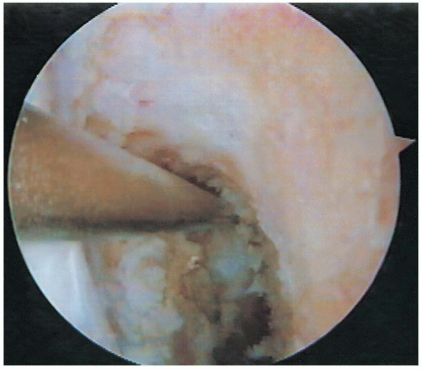
Ligamentum mucosum and some patellar fat pad, both of which may impede visualization, usually require débridement. Softtissues remaining on the notch laterally and posteriorly are also
débrided until the over-the-top position (i.e., the junction of the
roof of the intercondylar notch and the back wall of posterior cortex
of the lateral femoral condyle) can be recognized.
ArthroWands, such as the LoPro 90° or TurboVac 90 (ArthroCare, Sunnyvale, CA), can be used for hemostasis and further débridement of soft tissues. Throughout the procedure, special care is taken not to damage the native PCL.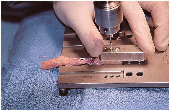 |
|
FIGURE 26-13. Bone plug graft preparation on a graft workstation.
|
5.5-mm, round burr is used to complete the notchplasty after an
adequate soft tissue débridement has been done. The minimum amount of
bone is removed from the medial aspect of the lateral femoral condyle
from an anterior-to-posterior direction and from an apex-to-inferior
direction to visualize the over-the-top position and to prevent
impingement of the graft.
Specialattention should be given not to misinterpret a vertical ridge (i.e.,
resident’s ridge), usually located two thirds of the way posteriorly,
as the over-the-top position; this ridge should be removed smoothly
until the true back wall is clearly identified. An arthroscopic probe
is used to verify that this position has been clearly reached. This
part of the procedure is crucial, because it determines the correct
isometric position of the femoral tunnel.
 |
|
FIGURE 26-14. Prepared bone-patella tendon-bone autograft.
|
 |
|
FIGURE 26-15. A and B: Arthroscopy of knee after the graft is harvested.
|
this point, the tentative position of the femoral tunnel can be
manually marked with an ArthroCare wand. The mark should be placed 7 mm
anterior to the back wall (to leave a 2-mm wall of posterior cortex
when reaming a 10-mm [5-mm-radius] tunnel) — and at the 1-o’clock
position in the left knee and the 11-o’clock position in the right knee.
Because it is the left knee in the illustrated case, the 1-o’clock position is used (Fig. 26-16).The proper position of the femoral tunnel is later confirmed with the
7-mm-offset transtibial femoral guide after the tibial tunnel has been
made.
portion of the graft. In
our case, 7 is added to 45 for a total of 52; therefore, the guide is
set at 52. Using this method minimizes the possibility of graft-tunnel
mismatch.
 |
|
FIGURE 26-16. Over-the-top position at 1 o’clock in the left knee.
|
proper placement of the guide pin, several parameters are used: the
posterior one half of the ACL stump footprint, the posterior edge of
the anterior horn of the lateral meniscus, the anterolateral aspect of
the medial tibial eminence, and 7 mm anterior to the PCL (Fig. 26-17).
After the proper position for the guide pin has been established, the
cannulated, calibrated guide pin sleeve is advanced through the C-ring
up to the anteromedial aspect of the tibia by retracting the incision
inferiorly. The sleeve should be placed on the tibial cortex halfway
between the tibial tubercle and the posteromedial border of the tibia.
With the arm of the target marking hook kept parallel to the slope of
the tibial plateau, the sleeve is advanced and secured against the
tibia (usually positioning it approximately 1 cm above the pes
anserinus and 1.5 cm medial to the tibial tubercle). The guide pin sleeve should not be overtightened, nor should excessive torque be placed on the C-ring.
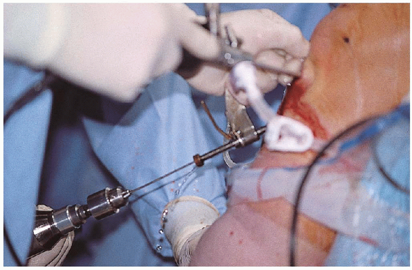
The 2.4-mm drill-tip guide pin is placed in the sleeve and drilled
through the tibia under direct arthroscopic visualization until the tip
of the pin is seen just penetrating intraarticularly (Fig. 26-18).
The sleeve is released, and the C-ring is removed.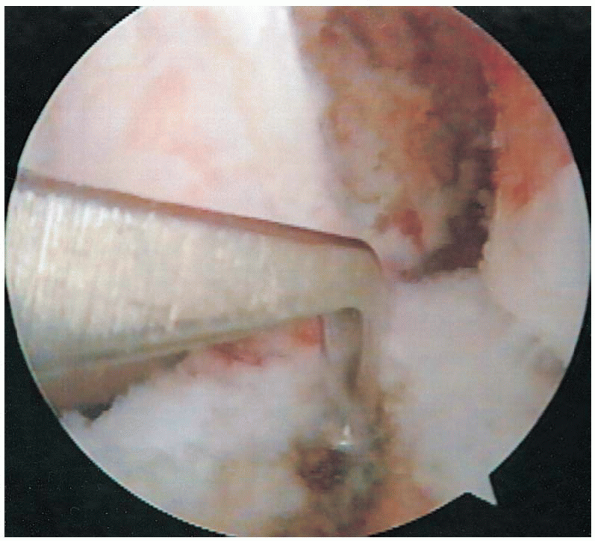 |
|
FIGURE 26-17. Intraarticular placement of the tibial guide.
|
 |
|
FIGURE 26-18. Tibial tunnel guide wire drilling with the use of a tibial drill guide.
|
the proper placement of the guide pin is verified, a curved curette is
placed intraarticularly over the guide pin to prevent it from further
advancement during drilling, and a 10-mm, cannulated-headed reamer is
used to precisely drill the tibial tunnel over the guide pin (Fig. 26-19).
The reamer and guide wire are removed. With a notchplasty-tunnel rasp
(Arthrex) placed through the tibial tunnel, the posterior edge of
intraarticular end of the tunnel is smoothed down. With an aggressive
shaver, the excess soft tissue, cartilage, and bone are removed from
the intraarticular end of the tunnel. The excess soft tissue, which can impede graft passage, is also removed from the tunnel entrance with sharp dissection.
A tibial tunnel cannula (Arthrex) is placed in the tibial tunnel to prevent fluid extravasation.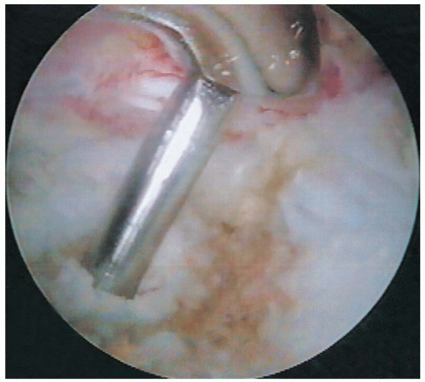 |
|
FIGURE 26-19. Tibial tunnel reaming over a guide pin.
|
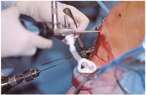
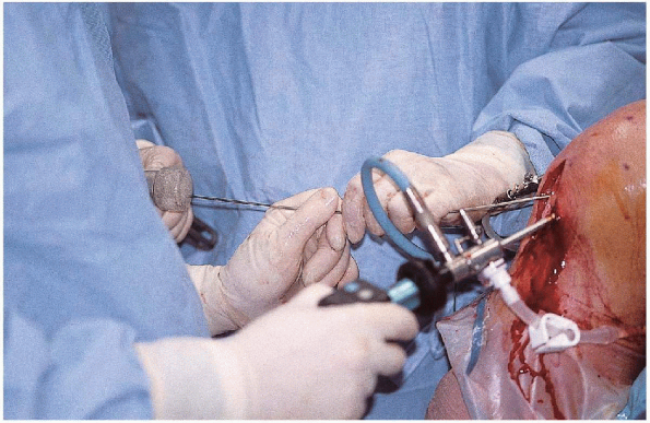
7-mm-offset transtibial femoral guide (Arthrex) is advanced through the
tibial tunnel and placed over the posterior edge of the back wall at
the 1-o’clock position (11 o’clock for the right knee). With the knee
flexed at 70 to 90 degrees, an extra-long guide pin with suture eye
(Arthrex) is placed through the femoral offset guide (Fig. 26-20).
If the tip of the guide pin is not close to the mark previously made to
approximate the femoral tunnel, the proper position of the femoral
tunnel should be reassessed. After the proper position of the femoral
tunnel is confirmed, the guide pin is drilled into the femur through
the cortex and out the anterolateral thigh. A 10-mm, cannulated-headed
reamer is carefully advanced through the tibial tunnel and past the PCL
over the guide wire. The femoral tunnel is then
carefully drilled under arthroscopic visualization in line with the
guide wire and with the knee flexed at the same angle the guide wire
was inserted.
The integrity of the posterior wall is periodically checked during the initial drilling.The femoral tunnel is drilled for a length of 25 mm (5 mm longer than
the 20 mm patella bone plug that is to be used in the femoral tunnel)
by using the calibrated laser lines on the reamer. The reamer is then
carefully removed past the PCL and out through the tibial tunnel. The
integrity of the posterior wall is again checked by arthroscopic
visualization, and 2 mm of posterior cortex should be remaining.
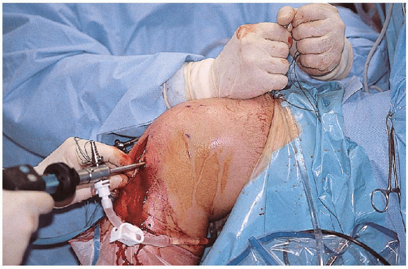
control of the graft must be maintained at all times. All the free ends
of the sutures from the patella bone plug are fed through the suture
eye of the guide pin. A vise-grip or pin puller is placed on the
proximal end of the guide pin, and the guide pin is carefully malleted
out. The cancellous portion of the graft should be oriented
anteriorly and should be passed through the tunnels in this
orientation. The sutures retrieved proximally at the anterolateral thigh are clamped, and the graft is passed with these sutures (Fig. 26-21).
Gentle traction is applied to the sutures from the tibial bone plug to
keep a minimal amount of tension needed for graft passage. After the
patella bone plug reaches the femoral tunnel entrance, a probe may be
needed to tease the graft through the femoral tunnel.
Theprevious mark made with an indelible marker on the cancellous side on
the tendo-osseus junction is helpful in keeping the correct orientation
while the graft is intraarticular. The
graft should pass with relative ease; otherwise, the bone plugs may not
have been sized correctly or soft tissue at the tunnel site (especially
at the entrance of the tibial tunnel) may be impeding smooth passage.
 |
|
FIGURE 26-20. Femoral tunnel guide wire drilling with the use of a femoral offset guide.
|
 |
|
FIGURE 26-21. Passage of the graft using sutures.
|
tunnel notcher (Arthrex) is placed in the anteromedial portal, and a
keyhole notch is placed at the entrance of the femoral tunnel. With
the knee hyperflexed at 100 to 110 degrees (this amount flexion limits
screw divergence), a 2-mm Nitinol guide pin (Arthrex) is placed through
a separate, more inferior, anteromedial portal into the femoral tunnel
through the notch between the anterior aspect of the femoral tunnel and
cancellous portion of the bone plug until the guide pin is seeded about
20 mm (Fig. 26-22).
With the knee in the same position and the bone plug flush with the femoral tunnel entrance, a 7 20 mm metal interference screw (Arthrex) is screwed over the guide pin
with a 3.5-mm, hex-head, cannulated screwdriver (Arthrex) through the
soft tissues into the femoral tunnel (Fig. 26-23).
As the screw is advanced in the femoral tunnel, increasing resistance
should be felt, and grinding should be heard as interference fixation
is achieved. The head of the screw should be advanced until the head of
the screw is flush with the femoral tunnel entrance.
The screwdriver and guide pin are removed.Isometry of the graft can also be checked at this time as well. With
constant tension on the tibial bone plug, the graft is cycled by
flexing and extending the knee 15 to 20 times.
 |
|
FIGURE 26-22. Placement of a guide wire for a femoral screw.
|
direct visualization of the entrance of the tibial tunnel, the
cancellous side of the tibial bone plug should be oriented anteriorly (Fig. 26-24).
A tunnel notcher (Arthrex) is used to place a keyhole notch in the
anterior aspect of the entrance of the tibial tunnel. With the knee as
close to full extension as possible, a 2-mm Nitinol guide pin (Arthrex)
is placed in the notch between the anterior aspect of the tibial tunnel
and cancellous portion of the bone plug until the guide pin is seeded
about 20 mm. With constant tension on the sutures from the tibial bone
plug, a 9
25 mm metal interference screw (Arthrex) is screwed over the guide pin
with the cannulated screwdriver. As the screw is advanced through the
tibial tunnel, increasing resistance should be felt, and grinding
should be heard as interference fixation is
achieved.
The head of the screw should be advanced until the head of the screw is
flush with the tibial tunnel entrance. The screwdriver and guide pin
are removed. If
less than 5 to 10 mm of tibial bone plug is protruding out the tibial
tunnel, the excess bone can be carefully burred to the level of the
tibial tunnel. If more than 10 mm of bone is protruding, alternative
means of fixation should be considered.
 |
|
FIGURE 26-23. Placement of a screw in the femoral tunnel.
|
 |
|
FIGURE 26-24. A bone-patella tendon-bone graft in the tibial tunnel.
|
shift are repeated to assess stability of the reconstruction. If
satisfactory, the sutures from each end of the bone plugs are removed.
Otherwise, the sutures may be used for additional fixation.
graft is used to bone graft the patella. If additional bone graft is
needed, this can be obtained from the tibial bone plug donor site. The
paratenon is closed over the patella with 0 Vicryl sutures. The patella
tendon is not reapproximated, but the overlying paratenon is closed
with 0 Vicryl sutures in a running fashion. The subcutaneous tissue is
closed with undyed 2-0 Vicryl sutures in an interrupted fashion. The
skin is closed with a 3-0 Monocryl suture in a running subcuticular
fashion. The 0.5-inch Steri-strips are placed transversely over the
incision for reinforcement. An injection of a mixture of 10 mL of 0.25%
Marcaine with epinephrine and 5 mg of Duramorph is injected
intraarticularly. The incision is covered with sterile dressings,
Webril, and an Ace bandage. A drain in not routinely used. The
extremity is placed in a hinged brace locked in full extension.
|
TABLE
26-1. HOSPITAL FOR JOINT DISEASES GUIDELINES FOR REHABILITATION AFTER ANTERIOR CRUCIATE LIGAMENT RECONSTRUCTION WITH A PATELLA TENDON GRAFT |
||||||||||||||||||||||
|---|---|---|---|---|---|---|---|---|---|---|---|---|---|---|---|---|---|---|---|---|---|---|
|
patient is allowed to bear weight as tolerated with the brace in full
extension and with crutches. Ice or a cold therapy unit is used
continuously for 3 to 5 days. The knee brace is worn for approximately
4 to 6 weeks during ambulation and sleep, and crutches are used until
adequate control of quadriceps is regained, which is usually for 2
weeks. The patient is allowed to shower in 7 to 10 days after surgery.
The patient is initially seen 5 to 7 days after surgery for a wound
check and for immediate initiation of an accelerated rehabilitation
program (Table 26-1) and then at 2 weeks, 6, weeks, 12 weeks, and 24 weeks.
Single-incision endoscopic anterior cruciate ligament reconstruction
using patella tendon autograft: minimum two-year follow-up evaluation. Am J Sports Med 1998;26:30-40.