
One – General Principles: Basics > Principles of Treatment > 7 –
Principles of Internal Fixation
a fractured limb not only reduces pain but also supports the healing
process. However, the first reports on modern techniques of internal
fixation are only about 100 years old. The brothers Elie and Albin
Lambotte from Belgium described in detail the essentials of what they
called “osteosynthesis” of fractures with plates and screws, wire
loops, and external fixators. Albin Lambotte (1866-1955) highlighted
the importance of anatomic reduction and stable fixation of articular
fractures as the only way to regain good joint function.44
While he planned and drew every fracture in detail, he also emphasized
the importance of careful soft tissue handling to preserve vascularity
and prevent infection. His pupil Robert Danis (1880-1962) introduced
the term “soudure autogéné”, or primary bone healing without visible
callus, which he observed when the fracture was anatomically reduced
and fixed with his compression plate. In 1950, the 32-year-old Swiss
orthopaedic surgeon Maurice Müller spent one day in the clinic of Danis
and was deeply impressed by the patients he saw and the results of
compression plating. Back in Fribourg, he got permission to treat a
patient with the new technique and compression plates, which he soon
modified and technically improved. Together with 13 other young Swiss
surgeons, he founded in 1958 the Arbeitsgemeinschaft für
Osteosynthesefragen (AO). The main representatives were Martin Allgöwer, Walter Bandi, Robert Schneider, and Hans Willenegger.54
They agreed on and adhered to strict rules and principles of surgery
and, thanks to a meticulous follow-up of every single fracture, they
were able to document their results and learn from the mistakes and
complications. Parallel to the Swiss AO, Gerhard Küntscher (1900-1972)
in Germany had developed the technique of intramedullary nailing, which
soon revolutionized the treatment of diaphyseal fractures especially of
the femur and tibia.43 In contrast
to the rigid fixation by interfragmentary compression, intramedullary
nailing was a splinting technique, which allowed for some motion at the
fracture site and therefore healing by callus formation. Rigid fixation
on one hand and the more elastic internal splinting on the other have
often been considered as competing techniques, while they are actually
complementary, each having its pros and cons and specific indications.
 |
|
FIGURE 7-1
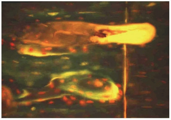
Direct or primary fracture healing as observed with absolute stability. A new Havers osteon transversing the osteotomy, thereby interdigitating across the osteotomy line. |
(i) to obtain full restoration of function of the injured limb and (ii)
for the patient to return to his preinjury status of activities, as
well as to minimize the risk and incidence of complications. The
purpose of the use of implants is to provide a temporary support, to
maintain alignment during the fracture healing, and to allow for a
functional rehabilitation.
 |
|
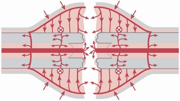
FIGURE 7-2
Secondary healing by callus as observed with relative stability. Schematic drawing of vessel ingrowth from the periphery to the fracture gap. |
treatment will be considered in this chapter. Any procedure will alter
the biological and biomechanical environment for fracture healing, and
every surgeon treating fractures should be familiar with those
alterations. From a mechanical and biological point of view, a
fractured bone needs a certain degree of immobilization, an optimally
preserved blood supply, and biological or hormonal stimuli in order to
unite. All three factors are important; the mechanical part is however
the easiest to quantify. We may distinguish two types of mechanical
stability: absolute and relative. Absolute stability is defined as
rigid fixation that does not allow any micromotion between the
fractured fragments under physiologic loading. It is best obtained by
interfragmentary compression and is based on preload and friction. More
elastic fixation as provided by internal or external splinting of the
bone is defined as relative stability which allows limited motion at
the fracture site under functional loading. The degree of stability
determines the type of fracture healing, which is either by primary or
direct bone remodelling (Fig. 7-1), or by
secondary or indirect healing with callus formation. Indirect fracture
healing by callus can take place in a much wider spectrum of mechanical
environments than primary or direct bone remodelling (Fig. 7-2). Callus will not form if there is no motion; however, if there is excessive movement, healing will equally be delayed.
describes, in a simplified manner, what occurs at a cellular level in a
fracture gap. Strain is the deformation of a material (e.g.,
granulation tissue within a gap) when a given force is applied relative
to its original form, thus it has no dimension. The amount of
deformation a tissue can tolerate before it breaks varies greatly. The
strain of normal intact bone until it breaks is “low,” about 2%, while
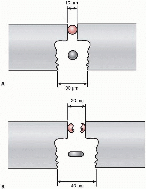
granulation tissue has a high strain tolerance of 100%.63 In a narrow fracture gap, a defined distracting force will disrupt the few cells within it (Fig. 7-3).
The same force applied to a wider gap filled with granulation tissue
will, however, only deform this tissue and not cause any rupture. In a
simple transverse or short oblique fracture, any deforming force is
acting very locally on the single fracture gap corresponding to a
concentration of stress, while in complex, multifragmentary fractures
the same force will be distributed
over
a wide range of different fracture fragments or gaps (stress
distribution). By applying the strain theory, a simple type A
diaphyseal fracture has a situation of “high strain.” Therefore, such a
fracture is best reduced anatomically and fixed by interfragmentary
compression (lag screw and plate), a method that produces a high degree
or absolute stability (Fig. 7-4).
 |
|
FIGURE 7-3 Strain theory by Perren: Panel (A) shows two cells (red and blue circles) in two different sized fracture gaps (10 pm and 30 pm). Panel (B)
is after 10 pm of distraction. The single red cell in a narrow gap will rupture upon minimal distraction (high strain), while the blue cell in a wide gap with the same distraction will just deform or extend (low strain). |
 |
|
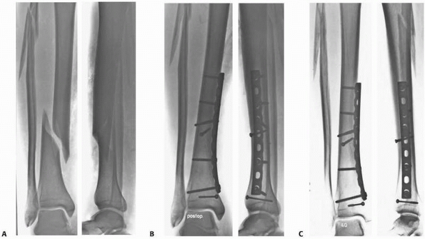
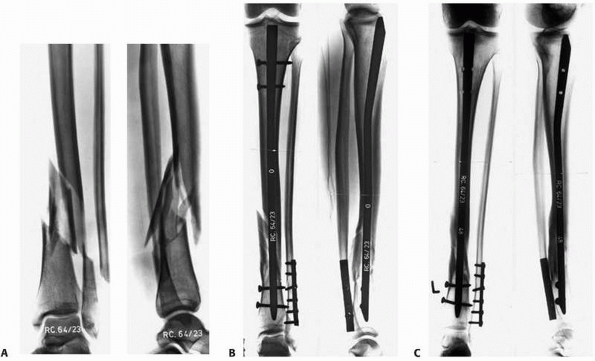
FIGURE 7-4 A simple tibia and fibula spiral fracture by indirect trauma (A)
is reduced anatomically and fixed with interfragmentary compression (lag screw and protection plate) providing absolute stability (B). C. Healing occurs without callus formation at 1-year follow-up. |
diaphyseal fracture corresponds to a “low strain” situation, which
profits from correct axial and rotational alignment and less rigid
fixation (locked intramedullary nail, bridge plate, or external
fixator) providing relative stability (Fig. 7-5).
It appears most important in simple fracture types treated with rigid
fixation that persistent gaps at the fracture site are avoided, while
in complex fractures treated with less rigid fixation such small gaps
may be tolerated (Table 7-1). Larger gaps are less well tolerated. Bhandari6 and Audigé1
have independently shown in large clinical series of surgically
stabilized tibia shaft fractures that persistent fracture gaps of over
2 mm were closely related or predictive for the development of a
healing delay or nonunion.
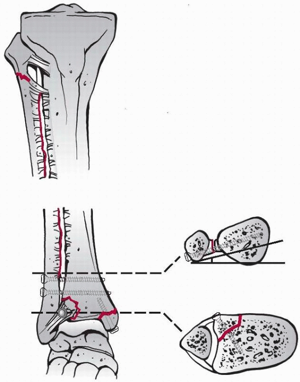
joint surface must be restored and the fragments should be fixed
rigidly by interfragmentary compression, while associated metaphyseal
comminution or a diaphyseal extension of the fracture can be correctly
aligned in all planes and bridged by an appropriate device (see Fig. 7-28).
concentration of forces inducing the fracture will determine the fracture type and the associated soft tissue lesions.56
As a result of the displacement of the fragments, periosteal and
endosteal blood vessels maybe disrupted and the periosteum will be
stripped.71 The statement that
“every fracture is a soft tissue injury where the bone happens to be
broken,” should emphasize the great importance of the soft parts, which
unfortunately are still often not considered and respected enough.
 |
|
FIGURE 7-5 A. Complex, distal tibia and fibula fractures by direct trauma B. Fixed after axial and rotational alignment with a locked intramedullary nail providing relative stability. C.
Healing occurred after proximal dynamization with callus formation. The fibula fracture was fixed because of the vicinity to the ankle joint. |
formation of granulation tissue within the fracture hematoma and is
dependent on a preserved or restored blood supply to the area. The more
extensive the zone of injury and the tissue destruction, the higher is
the risk for a delay of the healing process or for other complications.
Depending on the mechanism and the magnitude or energy of the insult
that caused the bone to break, direct and indirect fracture mechanisms
are distinguished which can usually be deducted from the radiographic
appearance of the fracture pattern. An indirect fracture mechanism,
like a rotation or bend, will cause a spiral or butterfly fracture,
respectively, with relatively little soft tissue injury. These
fractures generally heal rather uneventfully when adequately reduced
and immobilized by nonoperative or operative means (see Fig. 7-4).
In contrast, a direct blow will induce a local contusion of the skin at
a minimum, or more often will result in an open transverse or wedge
type fracture with an extensive area of soft tissue injury (Fig. 7-6). In open fractures, the severity or extent of the lesion is usually much more evident than in closed fractures.20
The latter may also involve important neurovascular structures
surrounding the bone. In closed fractures, occult injuries are
therefore more often missed.51 A
careful assessment, classification, and documentation of the fracture
and the soft tissue injury is therefore of great importance in the
planning, especially for correct timing, of surgery. As a rule,
it
is much safer to temporarily immobilize the zone of injury by traction
or more adequately by an external fixator, postponing definitive
fixation until the soft tissues have recovered.
|
TABLE
7-1 Relation of the Stability of Fixation (Absolute vs. Relative), the Type of Fracture (Simple or Complex), and the Size of the Fracture Gap to Fracture Healing |
||||||||||||
|---|---|---|---|---|---|---|---|---|---|---|---|---|
|
||||||||||||
 |
|
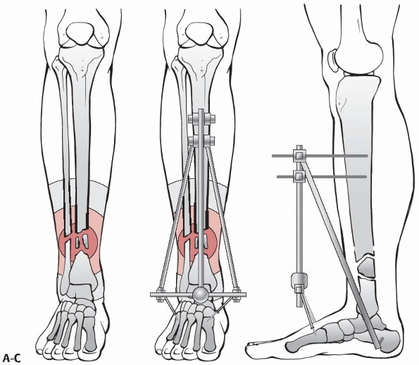
FIGURE 7-6 A. Schematic drawing showing zone of injury around a tibia and fibula fracture caused by direct trauma. B,C. Bridging external fixator to protect the zone of injury in a severely contused distal tibia fracture.
|
associated vascular injury, it may be advisable to perform emergency
fixation of the bone, followed by vessel repair and immediate or early
plastic reconstructive procedure to cover the tissue defect.
Decision-making under such circumstances requires much experience, and
it may be advisable to involve a senior surgeon or the entire team
including a plastic-reconstructive surgeon (see also Chapter 10).
caused by the accident, we must do our best to limit any additional
injury to the blood supply of the bone and surrounding structures.
Minimally invasive surgical approaches without exposure of the
fracture, indirect reduction techniques, and fixation devices that do
not additionally harm the blood supply to the bone should be used
wherever possible.
and planning process, which is essential in order to obtain a
predictable outcome and to prevent intraoperative problems, hazards,
and unnecessary delays.
consideration the patient, the fracture, and the soft tissues. Planning
includes the evaluation not only of the fracture and limb per se, but
of the whole patient. Factors like the history and mechanism of the
accident, the age of the patient, pre-existing vascular and metabolic
diseases, and the use of drugs, alcohol, and nicotine all may greatly
influence the outcome and therefore must be included in the
decision-making. The expectations of the patient, their profession, and
recreational activities should be known and discussed. The treatment
plan is adapted accordingly.
additional imaging requested if considered necessary. Computed
tomography (CT) scans with two- or three-dimensional reconstruction
usually give more information,10,47,57
while traction views (under anesthesia) may still be helpful in greatly
displaced articular fractures. The classification of the fracture will
help to communicate and discuss the type of treatment, to evaluate the
problems, and to make a prognosis as to the outcome. The soft tissues
and neurovascular conditions are then assessed carefully, as closed
fractures may also have severe involvement of these structures. The
timely diagnosis of a compartment syndrome and its correct treatment
may save a critically injured limb. The assessment and classification
of the soft tissue injury is often more difficult than that of the
fracture and requires much experience.
-
Timing of surgery
-
Surgical approach
-
Reduction maneuvers
-
Fixation construct
-
Intraoperative imaging
-
Wound closure/coverage
-
Postoperative care
-
Rehabilitation
may dictate a certain method of fixation, for example a complete
articular fracture will require open reduction and stable internal
fixation, other fracture types may be approached by different fixation
techniques or even by nonoperative treatment. The conditions of the
soft tissue, such as severe swelling or a skin contusion, may preclude
immediate surgery and make a staged procedure
recommendable.
Once the indication and best time for surgery has been established, the
type of anesthesia, positioning of the patient, use of a tourniquet,
and the need for prophylactic antibiotics or a bone graft has to be
communicated to the anaesthesia and operating room (OR) team as well as
the method of fixation, approach, reduction aids, type of implant, and
intraoperative imaging. The more complex the fracture and the
procedure, the more detailed the planning must be. Drawing the outlines
of a fracture on tracing paper will help to recognize the number,
shape, position, and relationship of the different fragments. Thereby,
the character and challenges of a fracture will be appreciated and the
experienced surgeon will be able to decide how to reduce and fix the
fracture without additional damage to the most vulnerable blood supply
of the area.
uninjured side including the adjacent joints, tracing paper, colored
pens, templates of the implants, a set of goniometers, and an x-ray
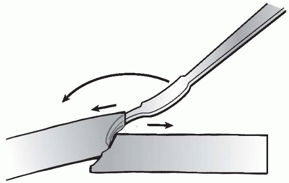
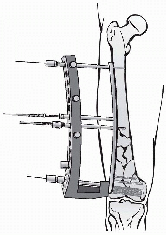
screen are needed for preoperative templating. Step one: the outlines
of the intact bone(s) are drawn. Step two: the outlines of the
fractured bone(s) are drawn, with the different fragments separated
from each other. Step three: the main fragments and the intermediate
pieces are reassembled on the drawing of the intact bones. To do so,
the separate fragments can be copied on different pieces of drawing
paper or cut with scissors. The restored fracture on paper helps
indicate how to best reduce the fracture and which function of the
fixation device (absolute or relative stability) will be utilized (Fig. 7-7).
The plan also indicates what size implant is needed and where and how
to place or introduce it to minimize additional soft tissue injury.
Finally, the reduced fracture with the implant in place is drawn, and
the different steps of applying the fixation device are numbered. For
an open fracture, the question of wound closure or coverage should be
addressed. The OR team will be grateful if a list of the required
equipment, instrument sets, reduction tools, intraoperative imaging,
and so forth, is provided.
 |
|
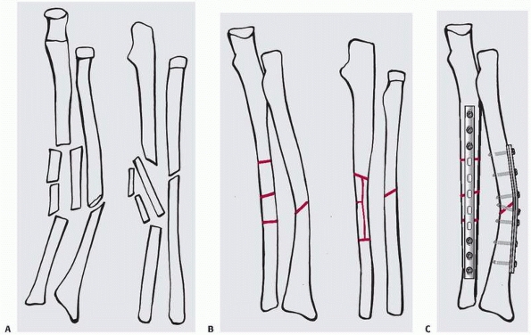
FIGURE 7-7 Planning on paper: first, the different fracture fragments are drawn separately on tracing paper (A). B.
They may be cut out with scissors to be assembled again, or they may be copied onto the outlines of the intact bones of the opposite side. C. Finally, the implants are added in the correct position, length, and function providing absolute (compression) or relative (bridging) stability. |
most newer radiology departments and online planning tools and
templates are under development and will soon be available, which will
hopefully make the whole planning process on personal laptops more
attractive, easier, and less time consuming. A good preoperative plan
will reduce OR time, make a procedure more efficient and thus be
beneficial to the patient.
fracture fixation of open as well as closed fractures is an
evidence-based standard treatment today,7,57
much discussion centers around the kind of antibiotic and the duration
of application. As there is a large variation in the recommendations
depending on national, regional, and local factors, we suggest that the
infectious disease specialist of a specific hospital should be
consulted. In general, a second generation cephalosporin with a broad
spectrum is recommended, applied as single dose 30 minutes before the
start of surgery or initiated before surgery and continued for
24
to 48 hours postoperatively. Furthermore, frequent wound irrigation
with saline during surgery is recommended (“Keep the soft tissues wet
and they will love you”) to reduce the risk of infection.3
The addition of antibiotics or antiseptics to irrigate solutions is
however debatable and not proven to be effective. The detailed
treatment of open fractures is discussed in Chapter 10.
factors including age, type of surgery, duration of immobilization, and
pre-existing disposition. The incidence of deep vein thrombosis (DVT)
is high in patients with fractures of the hip, pelvis, spine, and lower
extremity, while upper limb injuries are rarely the source of
thrombosis. DVT has a considerable morbidity with significant
complications and mortality. Similar to the use of antibiotics, the
recommendations for a thromboembolic prophylaxis vary greatly from one
institution to the other. Early postoperative mobilization of the
entire patient is probably the most effective prophylaxis but not
always possible. Low molecular heparin, aspirin, and intermittent
compression devices applied to the feet, as well as warfarin or
coumarin, are all recommended by some but also rejected by others, as
there is no evidence of superiority of one single method.
and/or splinting, positioning of the injured limb, and the initiation
of physiotherapy exercises. A general goal is to move the joints, the
injured limb, and the whole patient as soon as possible, usually by 24
hours after surgery, provided the fixation of the fracture is stable
and the soft tissues permit such an aggressive management. In the case
of lower limb injuries and if the patient is considered compliant, a
plan for early start of partial weight bearing should be made. In
patients that are not compliant, the fixation must be able to tolerate
early full weight bearing or the fracture has to be protected
externally by a splint or cast.
only one of the most important and most challenging steps in fracture
management, operative as well as nonoperative, but probably also the
most difficult part to teach and practice. The goal of reduction is to
restore the anatomic relationship of the fractured bone and of the limb
by reversing the mechanism of fragment displacement during the injury.
It seems a fact that due to the muscle insertions to the bone, a
fracture tends to redisplace in the direction and degree of the
original displacement. It is therefore important not only to assess the
radiographs and CT scans carefully, but also to appreciate the vectors
and forces of fragment displacement by muscle pull (Fig. 7-8).
is simple, multifragmentary, or has a bone defect, the correct
restoration of length, axial alignment, and rotation is considered an
adequate reduction. In the epiphyseal segment, however, a meticulous,
anatomic reconstruction of the articular surface and joint congruency
is advocated in order to obtain a good functional result. As such,
ambitious aims are sometimes difficult to achieve without risks, such
as long incisions and a wide exposure. A careful balance between a
perfect reconstruction and the necessary respect for the soft tissue
biology has to be chosen. Furthermore, irreparable damage to the joint
cartilage may be a limiting factor.
 |
|
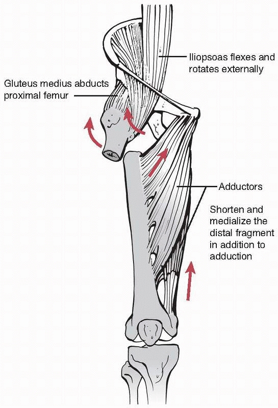
FIGURE 7-8
Typical displacement of a subtrochanteric fracture with external rotation, abduction, and flexion of the proximal and adduction of the distal fragment. |
the term of “biological fracture fixation” which refers not only to the
method of fixation, but also to the reduction techniques. Accordingly,
distinctions between direct and indirect as well as open and closed
reduction will be made. Although direct and open reduction and indirect
and closed techniques are usually associated, they are not necessarily
synonymous. At the end, the essentials are that any reduction or
fragment manipulation occurs atraumatic and gently, not causing any
additional harm to the vascularity of the already compromised fracture
fragments and soft tissues envelope.
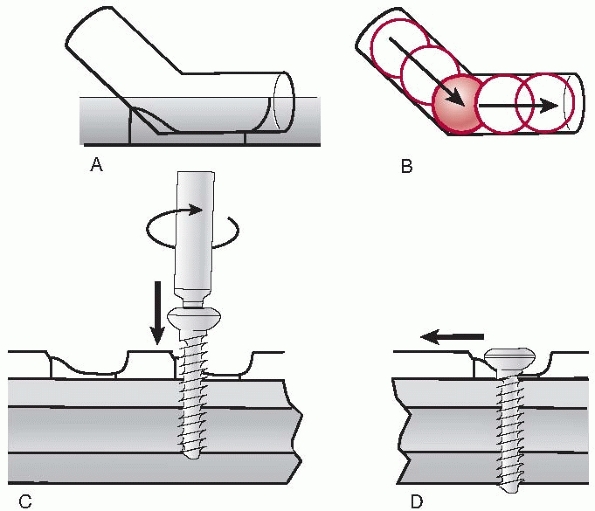
manipulated directly by the application of different instruments or
hands, which usually requires an open exposure of the fracture site.
Some newly developed instruments and devices, such as joy sticks, large
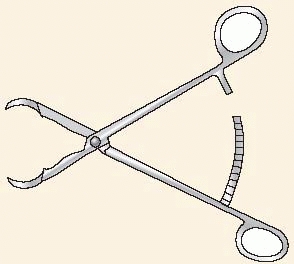
pointed reduction forceps, the ingenious colinear clamp, or new
cerclage wire tools, may also be applied directly to the bone through
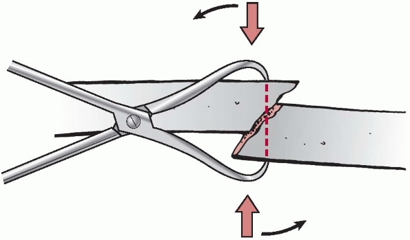
very small incisions and without wide exposure of the fracture (Fig. 7-9).
The application of these new techniques is called minimally invasive
surgery or minimally invasive plate osteosynthesis in spite of the fact
that thanks to the new instruments, direct fragment manipulation has
occurred.
 |
|
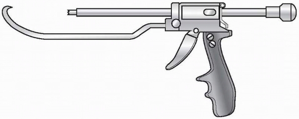
FIGURE 7-9 Colinear reduction clamp for minimally invasive approaches.
|
restoration of anatomy, though at the cost of more interference with
bone and soft tissue biology. A higher risk of infection and possibly a
delay in bony union that accompany stripping of the soft tissues are
further potential disadvantages.
alignment of the fracture fragments is being achieved without exposing
the fracture site as such by applying reduction forces indirectly —via
the soft tissue envelope—to the main fragments by manual or skeletal
traction, a distractor or some other means. The classic example of
indirect reduction is the “closed” insertion of an intramedullary nail
on a fracture table, where reduction has been obtained by traction on
the lower leg, while the nail provides the final alignment of the
fragments. The advantage of indirect reduction is that there is
virtually no exposure of the fracture site, which reduces the risk of
additional damage to the vascularity of the tissues, as well as that of
an infection. The disadvantages are that it is a demanding technique
and that the correct overall alignment of the fracture is more
difficult to assess, especially in rotation.
exposed, allowing to watch and inspect the adequacy of reduction with
our eyes. It is usually combined with direct manipulation of some
fragments, but can also involve indirect techniques such as the use of
a joint bridging distractor in an articular fracture.
-
Displaced articular fractures with impaction of the joint surface
-
Fractures that require exact axial alignment (e.g., forearm fractures, simple metaphyseal fractures)
-
Failed closed reduction due to soft tissue interposition
-
Delayed surgery where granulation tissue or early callus has to be removed
-
Where there is a high risk for harming neurovascular structures
-
In cases of no or limited access to perioperative imaging to check reduction
is essential to choose the best approach, the tools for a gentle
reduction, and the appropriate implant. In articular fractures, it is
usually sufficient to be able to see into the joint in order to
carefully clear it from hematoma and debris and to judge the cartilage
damage as well as the quality of reduction after the reconstruction.
The periosteum and any soft tissue attachments must be preserved
wherever possible, while separate stab incisions may help the placement
of pointed reduction clamps, temporary Kirschner wires (K-wires), or
the insertion of lag screws.
alignment by ligamentotaxis or the pull of the soft tissue envelope.
Longitudinal traction is the main force that may be modified by add- or
abduction, flexion or extension, and rotation as well as supporting
bolsters, etc. These maneuvers may be quite demanding and usually
require the presence of an image intensifier. Profound knowledge of the
anatomy (location of muscle insertion and direction of muscle pull) as
well as careful planning are prerequisites. Percutaneously applied
joysticks and special instruments may be helpful.19,41
If correctly applied, the advantages are minimal additional damage to
the soft tissues, safer and more rapid fracture repair, as well as
lower risk of infection.
-
Most diaphyseal fractures, where correct axial alignment, length, and rotation is considered sufficient for a good outcome
-
Minimally displaced articular fractures suited for percutaneous fixation
-
Femoral neck and trochanteric fractures, subcapital humerus fractures, and certain distal radius fractures
indicative of the amount of damage done to the biology of a fracture.
Much harm can be done through a short incision, but also little harm
through a larger exposure. All that matters is the gentleness of the
surgeon’s hands and his or her skills in managing the reduction process.
This can occur manually with the help of a fracture table or by
applying a distractor directly to the main fragments of a long bone or,
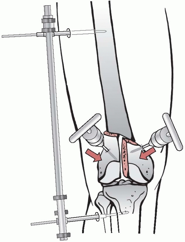
in an articular fracture, across the joint (Fig. 7-10).
While longitudinal traction will usually correct shortening, it may be
difficult to align the fragments in both the sagittal and coronal
planes.
There are a number of tricks described to overcome the problem. The
fracture table has the disadvantage that traction is usually applied
across a joint and that there are limited possibilities to move the
limb. The distractor, on the other hand, offers many possibilities and
more freedom of movement, but it is quite demanding to manipulate and
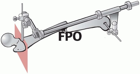
requires considerable practice (Fig. 7-11).2,4
 |
|
FIGURE 7-10 Joint bridging distractor to support reduction of a distal femur fracture with joysticks.
|
is the most commonly used as it comes in many different dimensions. The
points provide an excellent purchase on the fragments without stripping
or squeezing the periosteum; in osteopenic bone, they can, however,
penetrate through the thin cortex. Occasionally, a small hole created
with a drill or K-wire is helpful to gain purchase for the tip. The
forceps may be applied directly or percutaneously through stab
incisions.
 |
|
FIGURE 7-11
Femoral distractor applied in two planes to allow axial and rotational alignment such as for intramedullary nailing or minimally invasive plating. |
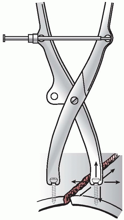
originally been developed for pelvic and acetabular fractures. Both are
applied to the heads of two screws that are inserted on either side of
a fracture (Fig. 7-13). The newest reduction
forceps is the collinear forceps which is no longer based on a hinge
between the two branches but on a sliding mechanism that allows a
linear movement (see Fig. 7-9). Thanks to
this, the new reduction tool can be introduced through very short
incisions or through narrow openings in the pelvis, which makes it
ideal for minimally invasive techniques.
Schanz screws), Hohman retractors for intrafocal manipulation, and
cerclage wires, while every surgeon has additional tricks and tools in
his or her personal armamentarium (Fig. 7-14).
intramedullary nail, plate, or modular external fixator may be used for
the reduction and fixation at the same time. Especially in conventional
nonlocked plating, angle blades and precontoured plates can be used to
reduce the fracture toward the plate.
promised to open completely new applications especially for hip and
knee replacement, but appears to still be in an early stage for acute
fracture reduction and management.29,35
fragments should be held reduced with temporary K-wires and/or a
forceps and then the reconstruction and axial alignment must be
carefully assessed in at least two planes preferably with the image
intensifier. However, the resolution of the images is not as precise as
that of radiographs, and the size of the field or picture is usually
too small to allow evaluation of the longitudinal axis of a bone or its
rotation. Another shortcoming of the image intensifier is the often
prolonged exposure to radiation for the patient, surgeon, and staff.
Several tricks have been described to overcome these drawbacks, and
some of them will be described in the chapter on intramedullary
nailing, where axial and rotational alignment is particularly
difficult. In articular fractures, inspection of the joint surface
occurs best either with the image intensifier or without any imaging at
all. The most
reliable
way to assess an articular reconstruction is with a CT scan, which is
becoming more available in the OR integrated into the new two- and
three-dimensional fluoroscopes. Arthroscopy has also been advocated for
minimally invasive surgical control of articular fractures.28,49
It offers advantages to evaluate menisci and ligaments as well as the
consistency of articular cartilage; however for the judgement of axial
alignment, open reduction usually appears to be superior.
|
TABLE 7-2 Useful and Frequently Used Instruments for Reduction
|
||||||||||||||||||||||||||||||||||||||||
|---|---|---|---|---|---|---|---|---|---|---|---|---|---|---|---|---|---|---|---|---|---|---|---|---|---|---|---|---|---|---|---|---|---|---|---|---|---|---|---|---|
|
 |
|
FIGURE 7-12
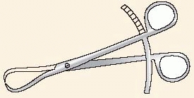
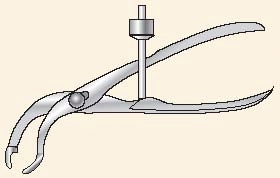
Pointed reduction forceps (Weber), which allow safe purchase of the bone without stripping of the periosteum. By manipulating the forceps (arrows), a simple oblique fracture can be easily reduced. |
devices applied either externally (percutaneously) or internally
(underneath the soft tissue cover). The former includes the many
different types of external fixators that will be described in Chapter 8.
Internal fixation devices stabilize the bone from within the medullary
canal (intramedullary nails) or are fixed to the exterior of the bone
(conventional nonlocked screws and plates and locked plates as well as
tension band wires).
 |
|
FIGURE 7-13
The Jungbluth forceps is applied with the help of the head of two screws that are inserted close to the fracture. Distraction as well as translation movements may be performed, which is especially helpful in the pelvis. |
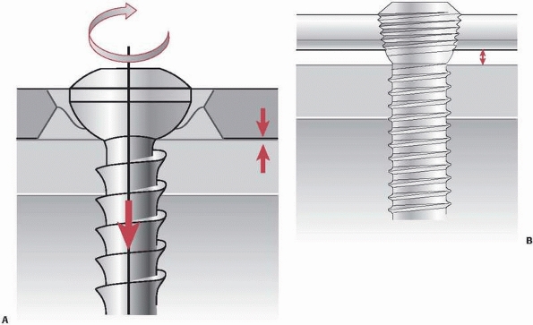
internal fixation, especially in combination with plates. A screw is a
powerful element that converts rotation into linear motion.
-
A central core that provides strength
-
A thread that engages the bone and is responsible for the function and purchase
-
A tip that may be blunt or sharp, self-cutting or self-drilling and -cutting
-
A head that engages in bone or a plate
-
A recess in the head to attach the screwdriver
materials. They are typically named according to their design,
function, or way of application.
 |
|
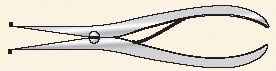
FIGURE 7-14 Hohman retractor for direct reduction of a simple fracture.
|
 |
|
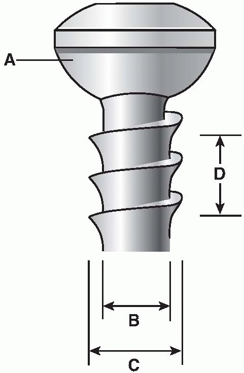
FIGURE 7-15 Schematic illustration of a conventional 4.5-mm cortex screw. A. Spherical screw head allowing a congruous fit in the plate hole. The minor diameter (B). The major diameter (C), and the thread pitch (D) are commonly referenced screw design parameters.
|
-
Design (partial or fully threaded, cannulated, self tapping, etc.)
-
Dimension of major thread diameter (most commonly used: 1.5-mm, 2.0-mm, 2.7-mm, 3.5-mm, 4.5-mm, 6.5-mm, 7.3-mm, etc.)
-
Area of typical application (cortex, cancellous bone, bicortical or monocortical)
-
Function (lag screw, locking head screw, position screw, etc.)
 |
|
FIGURE 7-16 A.
A conventional cortical screw applied as a plate screw. It presses the plate against the bone surface thereby creating friction and preload. B. Locking head screw. The screw head is firmly locked in the screw hole without pressing the plate against the bone. It provides angular stability. |
depending on the screw design and way of application. The two basic
principles of a conventional screw are to compress a fracture plane
(lag screw) and to fix a plate to the bone (plate screw). The more
recent designed locking head screws provide angular stability between
the implant and the bone (Fig. 7-16). The locking head screws have a head with a thread that engages with the reciprocal thread of the plate hole.16
This creates a screw-plate device with angular stability. Screw
tightening does not press plate against the bone surface. The load
transfer occurs through the locking head screws and the plate,
similarly to an external fixator, and not by friction and preload. As
the locked plate lies underneath the soft tissues, the principle of
this purely locked construct has been termed internal fixator (Fig. 7-17).
If a combination of conventional and locked screws are used in one
plate (“hybrid fixation”), the principle must be followed that in each
fragment, all conventional screws are inserted before inserting locked
screws. Lag screws (Fig. 7-18) can be applied
independently or through a plate hole. In both situations, compression
between two fragments or between the plate and the bone produces
preload and friction, which oppose fragment displacement by other
forces including shear force. Interfragmentary compression is the basic
element responsible for absolute stability of fracture fixation.
bone with a drill bit slightly larger in diameter than the minor
diameter of the selected screw. To ensure safe purchase of the screw,
it is recommended to cut a thread with a matching tap before the screw
is inserted especially in cortical as well as in hard cancellous bone
in young patients. In bone of softer quality, such as
cancellous
bone, screw insertion may be done without tapping. Alternatively, there
are also self-tapping screws, which reduce insertion time but require
some practice. The screw design and the technique of screw insertion
influence the amount of damage done and ultimately the holding power of
a screw. Thermal necrosis may be caused by dull drill bits or by
inserting pins and wires with a diameter larger than 2 mm without
predrilling, leading to loosening and ring sequester. It is the
surgeon’s responsibility to adequately prepare the holes.
 |
|
FIGURE 7-17 A. Dynamic compression principle: the holes of the DCP are shaped like an inclined and transverse cylinder. B. Like a ball, the screw head slides down the inclined cylinder. C,D. Because of the shape of the plate hole, the plate is being moved horizontally relative to bone when the screw is driven home.
|
 |
|
FIGURE 7-18 A.
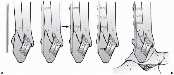
The first step of inserting a lag screw involves drilling the glide hole in the near cortex with a drill bit slightly larger than the major screw diameter. B. Into this hole, a drill sleeve is inserted to correctly center the pilot or threaded hole on the opposite or far cortex, which is drilled with a drill bit the same size as the minor diameter of the screw. After measuring the screw length with the depth gauge and tapping the thread in the far cortex, the cortex screw is inserted. C. Driving home the screw, the fracture surfaces will be compressed (interfragmentary compression). While the ideal screw direction to generate compression is at right angles to the fracture plane, this is only rarely possible. D. Therefore, the screw is directed between the perpendicular to the fracture plane and to that of the bone. |
-
The cortex screw thread is designed for use in cortical bone (see Fig. 7-15).
It is typically fully threaded but maybe partially threaded and is
commonly available in diameters from 1.0 to 4.5 mm. Each size has a
pair of drill bits corresponding to the screw’s major and minor
diameter and a tap. The drill corresponding to the major diameter is
used for drilling the gliding hole for a lag screw while the drill
corresponding to the minor diameter is used for drilling the threaded
hole. Today, self-tapping cortex screws are available and also
recommended, except for hard cortical bone of the young adult. Some of
the screws are also available in a cannulated version. -
The cancellous bone screw has a deeper
thread, a larger pitch, and typically a larger outer diameter (4.0- to
8.0-mm) than the cortex screws. They are indicated for metaepiphyseal
cancellous bone. The screw may be partially or fully threaded. Tapping
is recommend to open the cortex and in dense bone of the young adult. -
The locking head screws of locking plate systems (see Fig. 7-16B)
are primarily characterized by the threaded screw head. They may have a
larger core diameter and a relatively shallow thread with blunt edges.
This increases the strength and interface between screw and cortical
bone compared to conventional screws.73 Locking screws are used in combination with plates that have holes able to accommodate the threaded screw head.
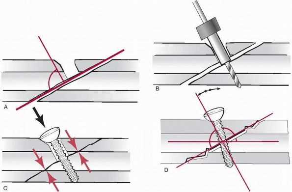
internal fixation is absolute stability thanks to interfragmentary
compression provided by a lag screw.64
A fully threaded conventional cortex screw is acting as a lag screw
when the thread engages only in the cortex opposite to the fracture
line (far cortex) and not in the cortex close to the screw head (near
cortex). This is obtained by first drilling a glide hole with a drill
bit slightly larger than the major diameter of the cortex screw. Next,
a drill sleeve is inserted into the gliding hole to precisely center
the threaded or pilot hole in the opposite cortex colinear with the
gliding hole, which is drilled with a smaller drill bit corresponding
to the minor diameter of the screw. After measuring the screw length
with a depth gauge, the thread in the far cortex is cut with a tap or a
self-tapping screw is inserted. As the screw advances in the threaded
hole, the head will engage in the near cortex and create preload and
compression between the two fragments. It is advisable to apply only
about two thirds of the possible torque to a lag screw corresponding to
about 2000 to 3000 N.61,72
The ideal direction of a lag screw, for generation of compressive
force, is perpendicular to the fracture plane. As this is often not
practical, an inclination halfway between the perpendiculars to the
fracture and to the long axis of the bone is typically chosen (see Fig. 7-18).
The head of a plate independent lag screw should be countersunk in the
underlying cortex, which increases the area of contact between the
screw and bone and reduces the risk of stress risers producing cracks.
A further advantage of countersinking is reducing the protuberance of
the large screw head underneath the skin (e.g., on the tibial crest).
|
TABLE 7-3 Various Screw Functions and Clinical Examples
|
|||||||||||||||||||||||||||||||||
|---|---|---|---|---|---|---|---|---|---|---|---|---|---|---|---|---|---|---|---|---|---|---|---|---|---|---|---|---|---|---|---|---|---|
|
|||||||||||||||||||||||||||||||||
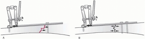
produce interfragmentary compression, provided that the thread engages
only in the fragment opposite to the fracture plane. A
washer may prevent the screw head from sinking into the thin metaphyseal cortex (Fig. 7-19).
 |
|
FIGURE 7-19
A partially threaded 6.5-mm cancellous bone screw will act as a lag screw, provided that the thread has its purchase opposite to the fracture line only. |
to fix a plate to the bone are called plate screws. They are introduced
with a special drill guide that fits into the plate hole either
centrally or eccentrically depending on whether axial compression is
demanded. The drill bit has the diameter of the minor diameter of the
screw, which may be self-tapping or not. By driving home the plate
screws, the plate is pressed against the bone which produces preload
and friction between the two surfaces.
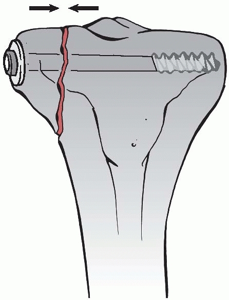
threaded screw that joins two anatomic parts at a defined distance
without compression. The thread is therefore tapped in both cortices.
An example is a screw placed between fibula and tibia in a malleolar
fracture to secure the syndesmotic ligaments (Fig. 7-20).
is the other principle providing absolute stability and inducing
primary or direct bone healing without visible callus. Today, the
classical open reduction with considerable exposure of the fracture and
internal fixation by plates and screws is being challenged by less
invasive and more elastic fixation methods, so called biological
techniques. Nevertheless, plating with absolute stability still has its
definitive place in operative fracture treatment, especially since we
have learned to better protect the delicate soft tissues during open
approaches. Fractures of the forearm bones as well as simple
metaphyseal fractures of other long bones are good indications for
conventional nonlocked plating, so are mal- and nonunions. In articular
fractures that require anatomic reduction and rigid fixation by
interfragmentary compression, plates will often support lag screws
and/or buttress the metaphysis. However, for most diaphyseal fractures
of the femur and tibia, intramedullary nailing is the criterion
standard.
 |
|
FIGURE 7-20
Example of a cortex screw in the function as a position screw between fibula and tibia to secure the ruptured syndesmosis. A thread is cut in every cortex, thus preventing compression between the two bones. The other screws are lag screws. |
which generally takes longer than healing by callus. Appearance of
callus after attempted rigid plate fixation is unexpected and a sign of
unplanned instability, which may lead to implant failure, healing
delay, or nonunion. The classical technique of compression plating
relies on pressing the plate to the bone surface, which may disturb the
blood flow to the underlying cortex, leading to local cortical
necrosis. This so called footprint of the plate induces a slow cortical
remodelling by creeping substitution and revascularization. What was
once considered stress protection is now interpreted as disturbed
vascularity of the cortex and has been addressed by new plate designs
with limited bone contact or more effectively by the internal fixator
principle, where there is no direct contact between plate and bone.60
screw head had a firm fit. Axial compression was obtained with a
removable external device. In 1967, the dynamic compression plate (DCP)
designed by Perren introduced a new principle of applying axial
compression by leveraging the interaction of a spherical screw head and
an inclined oval screw hole (see Fig. 7-17). The oval hole also allowed angulation of the screw in
different directions.66
The use of special drill guides precisely placed the screws in relation
to the plate hole in neutral or compression mode. These features of the
DCP greatly extended and facilitated the possibilities of application
of plates.
 |
|
FIGURE 7-21
Protection or neutralization plate to protect a simple fracture. The oblique screw inserted through the plate is a lag screw crossing the fracture plane, which adds to the absolute stability of the fixation. |
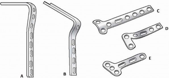
sizes only (4.5-mm narrow and broad), smaller sizes soon followed, as
did different designs for special applications such as the angle blade
plates for the proximal and distal femur, tubular plates,
reconstruction plates, the sliding hip screw, dynamic condylar screws,
and other form plates (Fig. 7-22).
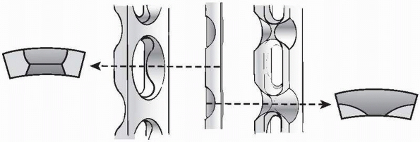
featured a new design of the under surface reducing the area of contact
between the plate and the bone to reduce the adverse effects of
pressure and friction on bone vascularity (Fig. 7-23).
This plate generation, designed with finite element analysis, displayed
an even distribution of strength throughout its length, irrespective of
the plate holes.65 All conventional
plates usually had to be contoured to match the shape of the bone, as
the plate was either pressed against the bone or the bone was pulled
towards the plate.
modern plates that also introduced a completely new principles of
fixation, the internal fixators or locking plates, will be discussed
later in a separate section of this chapter.
plates, the function that is assigned to a plate by the surgeon and how
it is applied is decisive for the outcome. There are five key functions
or modes any plate can have. In order to assign a specific function to
a plate, the preoperative plan has to take into account the fracture
pattern, its location, the soft tissues, and biomechanical surrounding.
 |
|
FIGURE 7-22 Different types and forms of early plates: 95 degree (A) and 130 degree (B) angle blade plates, T (C) and L (D) plates, and small fragment 3.5 distal radius plates (E).
|
-
Neutralization or protection
-
Compression
-
Buttressing
-
Tension band
-
Bridging
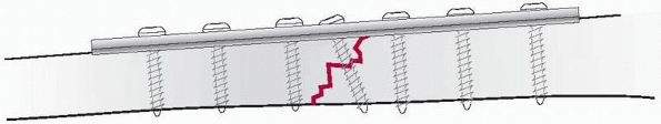
Stability. A simple, torsion, or butterfly fracture of the diaphysis or
metaphysis, caused by indirect rotational forces, is best reduced
anatomically and fixed by one or two lag screws providing
interfragmentary compression. It is normally recommended to protect the
lag screw fixation with the addition of a plate in order to protect it
or to neutralize any shearing or rotational forces, thereby improving
the stability (Fig. 7-24). This type of
classical plate application can also be performed with minimal exposure
of the fracture site and percutaneous reduction with the help of
pointed reduction forceps.
compression of a transverse fracture of a forearm bone is best obtained
by a compression plate. By slightly overbending the plate in relation
the shape of the bone and by eccentric placement of the screws, axial
compression is obtained. In short oblique fractures, in addition to
axial compression, a lag screw inserted through the plate and across
the oblique fracture plane will significantly increase the stability of
the fixation (see Fig. 7-24). In oblique
fractures, the plate is fixed first to the fragment with an obtuse
angle, so that when compression is added on the opposite side of the
fracture, the fragment locks in the axilla between plate and bone.
fractures such as malleolar fractures, tibia plateau, or distal radius
fractures,
we can observe how a large fragment has been displaced by shearing forces.8
To counteract these forces and keep the reduced fragment in place, a
plate is best applied in a position that locks the spike of the
fragment back in place, thereby preventing any further shearing or
gliding of the fragment. Buttress plates are often combined with lag
screws either through the plate or independently (Fig. 7-25).
 |
|
FIGURE 7-23
More recent plate designs (like the limited contact-DCP) feature the dynamic compression unit and have undercuts between the screw holes to reduce the area of contact between the plate and bone. This plate design has uniform strength of the plate throughout the plate.62 |
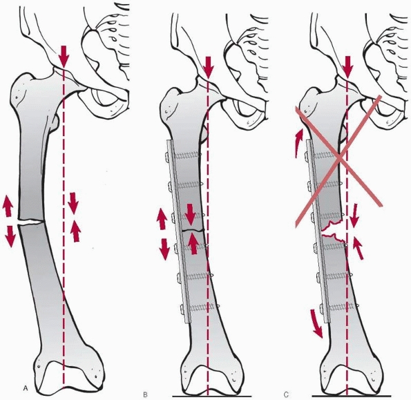
revealed that, with weight-bearing, the concave, medial side of the
femur is undergoing compressive forces, while the convex, lateral
cortex is under tension. An eccentrically applied plate on the convex
side of the bone will theoretically convert tensile forces into
compression, provided the opposite medial cortex is stable. In a
subtrochanteric fracture that is fixed with a plate, this implant will
function as a tension band provided the medial cortex, opposite to the
plate, has been reduced anatomically without any residual gap (Fig. 7-26).
indirect reduction and minimally invasive techniques with less rigid or
elastic fixations providing relative stability, a plate can also be
applied as an internal bridging device, similar to an external fixator.23,76
The best indications for bridge plating are comminuted diaphyseal or
metaphyseal fractures that are not suited for intramedullary nailing.
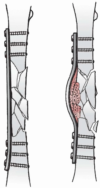
While we do not know the ideal working length of a plate precisely, it
is recommended to choose a plate about three times as long as the
fracture zone and to fix it with only a few firmly anchored screws
proximally and distally (Fig. 7-27).
 |
|
FIGURE 7-24
Axial compression with a plate can be obtained with the removable, articulated tension device. The plate is first fixed on one side of the fracture and then compressed in the axial direction. In case of an oblique fracture, a lag screw across the fracture plane will increase stability and compress the opposite cortex (A). To obtain an equal compression of both cortices of a transverse fracture, the plate is slightly over contoured before axial compression is applied (B). |
fixation, starting with Albin Lambotte, stressed 100 years ago the
importance of gentle soft tissue handling and minimal stripping of the
periosteum in order to preserve bone vascularity, the request for
anatomic reduction seemed somehow in contradiction with this principle.
In inexperienced hands, too wide exposures and extensive denudation of
bone occurred all too often, resulting in catastrophes such as delayed
or nonunions, infections, or the combination of the two. Mast et al.48
described in detail the advantages of indirect reduction techniques
without exposing the fracture fragments and created the term of
“biological plate fixation” with long bridging angle blade or straight
plates. In a study comparing a series of subtrochanteric fractures
treated by conventional open technique with indirection and bridge
plating, it was demonstrated that in the bridge plating group, the time
for union was shorter and predictable even without bone graft, the
complication rate was lower, and the functional outcome better.36 An important prerequisite was, however, that the procedure was carefully planned and well performed.
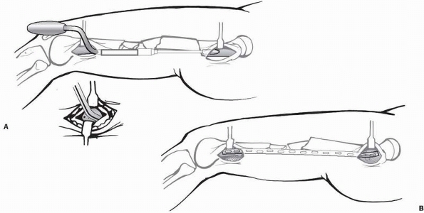
interlocking that in complex diaphyseal fractures, correct axial and
rotational alignment is all that is needed for early callus formation
and that anatomic reduction of every fragment is not required.
further developed these observations and ideas by minimizing the
approaches to short incisions far away from the fracture focus and by
inserting extra long plates via a bluntly prepared submuscular space
close to the bone and across the fracture (Fig. 7-28). The screws were inserted through equally short incisions and straight through the muscles. In
cadaver studies, Farouk et al.15
could show that the perforator vessels were not injured by these
tunnelling maneuvers. Similar to the rapid appearance of callus in
intramedullary nailing, the healing of these minimally exposed
fractures fixed with only relatively stable bridge plates occurred very
consistently with early callus formation.
 |
|
FIGURE 7-25
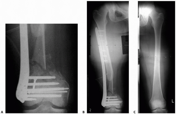
A buttress plate or antiglide plate has the function of preventing any secondary displacement of an oblique fracture in the metaphysis of a bone. The example shows the application in a malleolar fracture, where the plate is positioned on the posterolateral aspect of the distal fibula. A. The different steps and the sequence of introducing the screws are illustrated. B. Final construct after addition of lag screw. |
 |
|
FIGURE 7-26 By placing the plate in a transverse femur fracture (A) to the lateral aspect of the femur (B),
this implant will undergo tensile forces that are theoretically converted into compression at the fracture site. A precondition is that the bone opposite to the plate has close contact to resist the compressive forces. If the essential medial support is missing, the plate is more likely to break due to fatigue (C). |
higher incidence of axial and rotational malalignment just as in
intramedullary nailing,75 especially
in the femur. Furthermore, the intraoperative radiation exposure of the
patient and staff is higher, but may be reduced when navigation
techniques are refined and used more in the future.
 |
|
FIGURE 7-27
Bridge plating can be performed with any plate of adequate length. Nevertheless, the new locking plate systems are considered ideally suited for bridge plating and simplify the technique of minimal invasive application. The bridging device should be about three times the length of the fracture zone providing relative stability. |
 |
|
FIGURE 7-28 Minimally invasive plate osteosynthesis with blunt percutaneous tunnelling distally (A) and insertion of a plate without exposing the comminuted fracture zone (B).
|
and proximal and distal tibia that often show extensions into the
diaphysis, a combination of open anatomic reduction and stable fixation
of the articular block with minimally invasive bridging fixation of the
metadiaphysis can be recommended (Fig. 7-29).
contact and friction between a plate and the bone surface, Tepic and
Perren78 reported about a new principle of fracture fixation based on what they called the internal fixator (Fig. 7-30A,B).
The first development was the point-contact fixator (PC-Fix), where
every screw head was locked in the plate hole through a tight fit
between the conical shape of the head and the plate hole (Fig. 7-30C).
The stability of the fixation was therefore not based on compressing
the plate onto the bone or on preload and friction, but depended on the
stiffness of the plate screw construct. As the locked plate is not
based on friction between the plate and the bone, there is no
requirement for contact with the bone surface. Leaving a narrow free
space between the implant and the bone preserves the periosteal blood
flow and the underlying cortex remains vital, which appears to increase
resistance against infection.14 A
further feature of the locking head screws is the angular stability of
the construct, which prevents any secondary displacement or collapse of
fixation.13 There is no need for a
precise contouring of the plate to the shape of the bone with a pure
locked plate construct, as plate is not pressed against bone as in
conventional nonlocked plating. Last but not least, the locking head
screws often have a larger core diameter (4.0- vs. 3.0-mm), which
increases their strength, while the thread may be shallow as it adds
very little to the resistance to pullout. Thanks to the angular
stability of the screws, any bending forces will have to displace and
pullout
the entire screw-plate construct together and not one screw after the other as in conventional plating (Fig. 7-30D,E).121
This feature has proven most useful in poor quality or osteoporotic
bone as well as in periprosthetic fractures, where often only
monocortical screws can be inserted beside the shaft of a prosthesis.31
 |
|
FIGURE 7-29
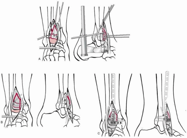
A combination of conventional open reduction and internal fixation with minimally invasive plate osteosynthesis in a pilon fracture. A. After initial provisional treatment with a bridging external fixator, the articular block is reconstructed anatomically and held with K-wires. B. The articular fragments are then fixed by lag screws. C. To secure the screw fixation and to bridge the metaphysis, an anterolateral L-shaped pilon plate is inserted percutaneously with minimally invasive plate osteosynthesis technique. |
-
No requirement for direct contact to the underlying bone, preservation of periosteal blood flow
-
Improved construct stability in osteopenic bone
-
Resistance to secondary collapse or screw displacement
-
No need for precise plate contouring
had developed a similar system with conventional plates and screws,
which was applied to the medial aspect of the tibia but outside the
skin and where the so called “platform screws” were locked with some
sort of washers in the screw holes (Fig. 7-31). Also, Reinhold in 1931 and Wolter in 1927 had already described the idea of angular stability or locked plating.
fixator principle was shown in a series of over 350 forearm fractures
that were fixed with the PC-Fix.21 The next development was the locked plate less invasive stabilization system (LISS) for the distal femur.39
It combines the fixed angle device with the possibility of a minimally
invasive plate insertion technique using a special jig and monocortical
and self-drilling and self-tapping screws that are introduced through
short stab incisions. The advantages of the monocortical screws were
seen in the single step insertion through stab incisions and a jig.
They, however, lack torsional control seen with bicortical screws.
Locked plating systems (Figs. 7-32 and 7-33)
have improved the surgical fixation of distal femur fractures by making
the clinical results more reliable especially in complex fracture
situations, such as osteoporotic and periprosthetic fractures.39,41,42,75
While the original LISS only accepted locking head screws, there was a
rising demand for the ability to also use conventional screws in a
plate with locking capability.16,41
With the further development of locked plates, more and more plates
have become precontoured to fit the periarticular anatomic regions (Fig. 7-34).
-
Conventional compression, protection, or buttress plates with conventional nonlocked screws
-
Pure locked plating with all locking head screws
-
Hybrid plating with a combination of
conventional nonlocked screws (to use plate as template for reduction)
and locked screws (for advantages of fixed angle support of end segment
fractures and improved fixation in osteoporotic bone)
 |
|
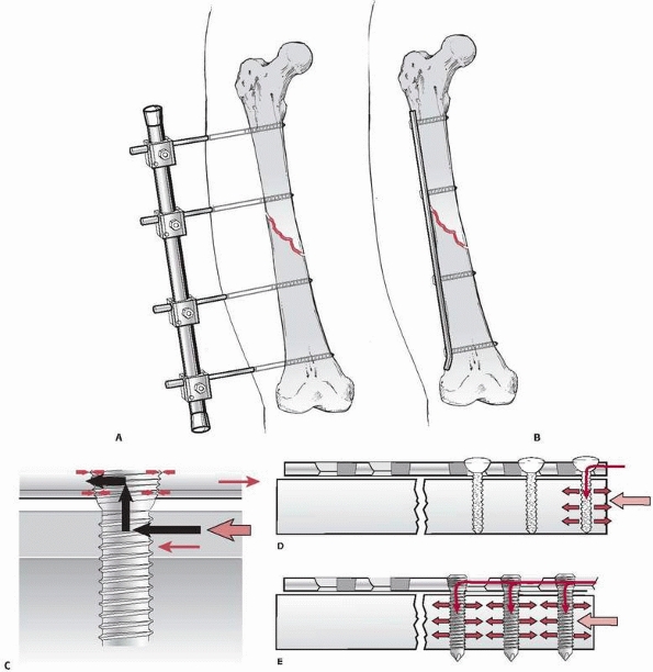
FIGURE 7-30 The principle of the “internal fixator” is based on moving an external fixator (A) close to the bone and underneath the soft tissue envelope (B).
A plate replaces the longitudinal rod and the locking head screws provide the angular stability of the clamps and Schanz screws. C. The force transfer in the internal fixator principle occurs primarily through the locking head screws across the plate and fracture. It is not dependent on preload and friction as in conventional plating, but rather on the stiffness of the fixator device. The locked plate does not have to touch the bone surface and therefore interferes less with the periosteal blood flow.79 D. In conventional plating, the screw head is allowed to toggle under loading. This process of load concentration starts at the end screw and continues from one screw to the next until the plate is completely pulled out. E. In locked plates, the angular stable screws prevent a load concentration at a single bone screw interface by distributing the load more evenly. To pull out a locked plate, much greater forces are needed as all screws have to be loosened at the same time.18,67 |
 |
|
FIGURE 7-31
A locked plate as it was developed by the Polish Zespol Group in the 1980s, where the plate remains outside the skin cover. The screws are locked with some sort of washers in the plate holes. |
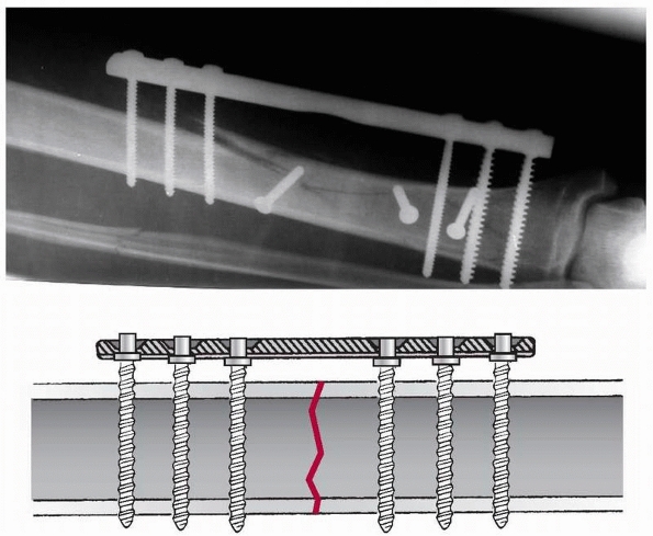
aspects have to be followed to avoid failures. Once a locking head
screw has been inserted in a bone segment, no conventional screws
should be added in the same segment, as this would create unwanted
tension forces within the plate and bone. The sequence should be “lag
first, lock second.” A reduction screw may be used to approximate a
fragment to the locked plate as an indirect reduction tool and then
locking screws are added to keep the fragment in place to the plate.
 |
|
FIGURE 7-32
Locked plate fixation for distal femur fractures. After reconstruction and preliminary fixation of the articular fracture components under direct vision, the plate can be inserted in a submuscular space with a special jig. The locking head screws are introduced percutaneously through the jig. |
 |
|
FIGURE 7-33
Clinical example of a “floating knee,” proximal tibia combined with a distal femur fractures, extending into both shafts and extensive open soft tissue injury (A), fixed by locking plates (B). After reconstruction of articular congruency with lag screws, the locking plates were placed percutaneously to the lateral aspect of the tibia. C. Follow-up after 1 year with good restitution of function. |
 |
|
FIGURE 7-34
Precontoured implants, like the locking plate for the distal femur, can facilitate reduction in complex fracture situations. This open fracture had significant metaphyseal bone loss. In accordance to the anatomic fit of the plate, the distal screws were placed parallel to the anteroposterior joint line of the distal femur. (A) Following this intraoperative guideline, the postoperative films show a good alignment (B) similar to the uninjured contralateral side (C) (further secondary bone graft was required to bridge the defect). |
accept splinting devices of different designs and sizes. The major
advantage is the biomechanical ideal position of the implant in the
center of the bone. On the other hand, a major problem is how to
control axial displacement or neutralize rotational forces. The
interlocking techniques have helped to solve these drawbacks to a great
extent. Depending on the anatomy, the insertion can usually occur
closed, without exposure of the fracture focus, in an ante- or
retrograde direction. A closed procedure would require the availability
of an image intensifier in the operating room for reduction and
interlocking.
for the femoral and tibial diaphysis. Recently, with new nail designs,
the spectrum of indications has been extended to even intra-articular
fractures of these bones (Fig. 7-35). For the
humeral shaft, intramedullary nails are an option competing with the
still very popular and more versatile plating techniques. Flexible
nails as used in pediatric fractures45
have been advocated for the clavicle, while nailing of the forearm
bones has not yet proved to be equal or superior for the fixation for
ulna and radius fractures due to the difficulty of reliable locking
systems that can control the rotational forces.
used solid metal rods for femur fractures and pointed to the rapid
healing, preservation of soft tissues, and periosteum as well as the
abolition of prolonged plaster cast immobilization. The Rush brothers69
presented their technique with multiple flexible intramedullary pins in
1927. The most important contributions to intramedullary fixation,
however, came from Gerhard Küntscher43
(1900-1972) who performed a number of animal experiments and perfected
not only the nailing technique but also the implant shape and design.
He requested a tight fit between nail and bone to achieve a higher
stability and to allow compression of the mostly transverse fractures
under load. To extend the area of contact within the medullary cavity,
he started to ream the canal in order to insert thicker, longer, and
slotted cloverleaf nails. Herzog,25
in 1950, introduced the tibia nail with a proximal bend and lateral
slots at the distal end to accept antirotational wires. Shortly before
his death, Küntscher43 designed the “detensor nail” for comminuted femur
fractures with a sort of interlocking device. This idea was further developed by Klemm and Schnellmann38 in Germany and Kempf et al.34 in France and were precursors to today’s interlocking nails.
 |
|
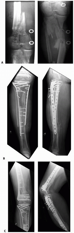
FIGURE 7-35 Intramedullary nailing systems offer possibilities to stabilize simultaneously ipsilateral trochanteric and shaft fractures. A. A 38-year-old multitrauma patient stabilized with an antegrade femoral nail with retrograde locking. B. The healing of both fractures was already reliable after 14 weeks (C,D).
|
original concept was based on the principle of elastic deformation or
“elastic locking” of the nail within the medullary canal. To increase
the elasticity, the hollow cloverleaf nail was slotted, and reaming of
the canal enlarged the area of contact and friction between the nail
and the bone (working length). Nails with larger diameters had an
increased bending and torsional stiffness. The weak point of the first
nails remained the poor resistance to axial (telescoping) forces and
rotation, especially in comminuted fractures. The introduction of
interlocking screws and bolts at the proximal and distal end of the
nail addressed these issues rather well; there remains, however, the
problem of the strength and purchase of the locking screws in the bone.
This problem is not yet completely solved as twisted blades and an
increase in screw diameter and number (larger and more holes) may
weaken the nail ends. Based on the positive experience and data of
Lottes,46 who presented very low infection rates in open tibia fractures with the use of solid nails that
were introduced without reaming, thinner, solid tibia nails with holes
for interlocking were developed. At the beginning, those thin nails
were to be inserted without reaming but with mandatory interlocking as
a temporary splint in open tibia fractures.70
Animal experiments showed that after nail insertion, the endosteal
blood supply was not destroyed to the same extent as after reaming and
also that the resistance to infection was much higher if solid nails
were compared with tubular ones.50
The clinical experience as to the infection rate in open fractures was
most encouraging; however, the time to union took longer, especially in
the majority of cases where the original concept of secondary exchange
nailing to a thicker nail was not followed. The enthusiasm for the new
nails without reaming rapidly extended their indications and use also
to closed and highly complex tibia and femur fractures. This resulted
in a higher incidence of delayed and malunions due to a poorer
mechanical stiffness of the construct, especially in long bone
fractures of the lower extremity.9,12,70
anatomic region, the use of intramedullary nails has both local and
systemic effects, some of which may be beneficial while others may be
detrimental to the patient and fracture healing.
inevitably associated with damage to the endosteal blood supply, which
was shown to be reversible within 8 to 12 weeks.74
Experimental data have also shown that the cortical blood perfusion is
significantly reduced after reaming of the medullary canal, if compared
to a series without reaming.37
Accordingly, the return of cortical blood flow takes considerably
longer after reaming than in the unreamed cases, which may have an
influence on the resistance to infection, especially in open fractures.
Furthermore, tight fitting nails appear to compromise the cortical
blood flow to a higher degree than loose fitting ones.30
Reaming of a narrow medullary canal may be associated with a risk of
heat necrosis of the bone and surrounding tissues especially if blunt
reamers and/or a tourniquet are used.32,56
On the other hand, the bone debris produced during the reaming has been
shown to act like an autogenous bone graft, enhancing fracture healing.17,27
Meta-analysis of current clinical studies found “gentle” reaming
superior to the undreamed technique for reliable healing of long bone
fractures in closed and low degree open fractures.9
pulmonary embolization, coagulation disorders, humoral, neural,
immunologic, and inflammatory reactions. The development of
posttraumatic pulmonary failure after early femoral nailing in the
polytrauma patient with chest injury appears to be more frequent
following reaming of the medullary canal than without it.58
In clinical and experimental studies, the passage of large thrombi into
pulmonary circulation has been demonstrated with intraoperative
echocardiography especially during the reaming process and, to lesser
extent, when introducing the reaming guide.80
Measurements of the intramedullary pressure have shown values between
420 and 1510 mm Hg during reaming procedures compared with 40 to 70 mm
Hg when thin solid nails were inserted without reaming.52,53
Nevertheless, there is an ongoing controversy between the advocators of
reamed nailing also in the multiply injured patient and those who are
recommending the use of thinner solid or cannulated nails without
reaming. The young adult with a simple transverse femoral shaft
fracture and a high injury severity score (>25) appears to have an
increased risk for pulmonary complications, which is why there is the
recommendation for a staged nailing procedure according to the concept
of damage control surgery (DCS) under such circumstances. DCS starts as
soon as possible with the stabilization of the femoral shaft fracture
with an external fixator followed by a conversion to an intramedullary
nail after 5 to 10 days (window of opportunity).33
The described systemic responses of intramedullary nailing of femoral
shaft fractures seem to be much more critical than in tibial shaft
fractures, where such effects have hardly ever been observed.
entire nailing systems available for the femur, tibia, and humerus.
Forearm nails are also on the market, but they have not proven to be
superior or as versatile as the fixation with plates. Originally,
intramedullary nails were offered in a tubular, usually slotted form,
while today solid and especially cannulated nails are most popular. In
children, the elastic nails have become the implant of choice for long
bone fractures.45 The implant
material is either stainless steel or a titanium alloy. The holes or
openings for interlocking devices are usually situated at either end of
the implant and oriented in different directions; some nails also have
locking possibilities throughout the entire nail length.
midshaft fractures to fractures involving the proximal and distal femur
and tibia as well as the proximal humerus.
the shape of the medullary cavity and the bone. The correct diameter
and length of the nail should to be selected beforehand; unfortunately,
the accuracy of templates is rather poor. The best tool is probably a
radiolucent ruler placed on the intact contralateral leg under C-arm
control or measurement with the intramedullary guidewire.
starting trajectory of the nail, which varies from one type of nail to
the other (Fig. 7-36). A misplaced starting
point may lead to axial and/or rotational malalignment that is usually
tricky to correct; even additional stress fractures have been
described. It is therefore advisable to study the technical guide of a
specific type of nail carefully and to check the correct entry point
and direction of the guidewire with the image intensifier preferably in
two planes.
specific bone, with or without a fracture table, with the help of a
distractor, or in a supine or in a lateral decubitus position, etc. As
each way has its pros and cons, much depends on the experience of the
OR team and the surgeon. It appears most important for any patient
positioning that the nail entry point can be clearly seen in two
projections with the C-arm and the same holds true for the distal
locking procedure.
 |
|
FIGURE 7-36
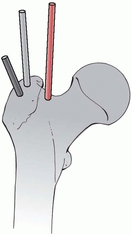
Various starting points and trajectories for antegrade femoral nailing. The correct entry point is crucial, but may vary from one type of nail to the other. (Always study the recommendations of the manufacturer as to the recommended nail entry point!) |
problem. The guidewire can usually be inserted easily into the opposite
fragment or a solid nail or reduction device can be used as a joystick.
In metaphyseal fractures, the correct alignment may be much more
difficult especially in the proximal or distal tibia. Blocking or
Poller screws40 may be helpful to guide the nail in the right direction (Fig. 7-37).
The technique of the Poller screws can be used to decrease the
functional width of a wide metaphyseal cavity or to force and redirect
the nail into a particular direction for a better alignment or improved
stabilization. The use of the screw can be temporary or definitive.
This technique is especially helpful to steer the nail into the “right”
direction, after being misplaced in the first attempt.
serves as an aiming device for locking the driving end of the nail with
bolts, blades, or locking screws. Placement of the far locking device
is usually more difficult as during the insertion, most nails are more
or less distorted so that the locking holes are not in the original
alignment anymore. Far locking must therefore be done in a “free hand”
technique or with the aid of aiming devices usually mounted on the
drill. Tight fitting nails tend to distract the fractures resulting in
wide gaps, which may lead to increased compartment pressure as well as
to delayed or nonunion.5 It is
therefore recommended to lock first at the far end, then to backslap
the nail, and then to lock the driving end. Finally, locking can be
done in a static or dynamic mode, while it is advisable to use at least
two locking screws at either end of the nail to control rotation in a
reliable way. Static locking is recommended for complex fractures to
prevent telescoping, while dynamic locking is advisable in short
oblique or transverse fracture to allow fracture compression during
weight-bearing.
However, in more complex, segmental, or comminuted fractures or in
floating knee injuries, it may be difficult to judge the correct axial
alignment. The most useful intraoperative indicator of an acceptable
coronal plane alignment is when the nail entrance point is correct and
the nail is centrally placed in the distal fragment (or proximal
segment in retrograde nailing). In the lower extremity, the long cable
of electrocautery, a C-arm, and the patient in supine position is
helpful to judge the right direction. The cable is centered to the
femoral head and distally to the middle of the ankle joint under
radiographic view. At the level of the knee, the cable should now run
exactly through the center of the joint as well. Any deviation
indicates an axial malalignment in the coronal plane.
is more difficult and less accurate. There are several radiologic signs
like the size of the diameter of two adjacent fragments or the
projection of the greater trochanter in relation to the patella in the
anteroposterior view, but they are not very reliable. With the patient
still on the OR table, internal and external rotation can be performed
to reliably check the rotation in comparison with the uninjured side.
The most accurate evaluation is with a few CT slices through the knee
and the hip joint allowing a comparison with the uninjured side.24
the long bones is the criterion standard. It is a minimally invasive
procedure allowing early weight-bearing and has a good chance of rapid
and undisturbed fracture healing.
who observed that a curved tubular structure when subjected to an axial
load always presents a tension side on the convexity and a compression
side on the concavity. The same occurs when a straight tube or bone is
loaded eccentrically like in the femur, where tensile forces are on the
lateral and compression on the medial side. By applying a tension band
device laterally, these tensile forces are converted to compression
forces, assuming the opposite side is stable and has good contact.
fragments as in the olecranon, patella, or the avulsion fracture of the
greater tuberosity of the humerus, a tension band will neutralize the
distraction forces and underflexion of the joint the fragments will be
compressed (Fig. 7-38). We therefore speak of
dynamic tension bands providing absolute stability and encourage the
patients with tension band fixation of one of these joints to regularly
perform flexion exercises.
even an external fixator, if applied correctly to the tension of a
fractured bone, can act as a tension band. The tension band device
must
withstand tensile forces, the bone must resist compressive forces, and
the cortex opposite to the tension band must be exactly reduced without
a gap.
 |
|
FIGURE 7-37 A.
Example of Poller screws in the femur to correct a valgus malalignment of the distal fragment. After the nail was backed out, a 3.5-mm cortical screw was placed (B,C) to steer the nail into the appropriate position (D-F). G-I. Postoperative control and healing after 1 year. In this case, to correct valgus with a blocking screw, the screw must be placed lateral to the nail and near the fracture or medial to the nail and far from the fracture. |
inserted through a drill hole in the bone, or it can be placed through
the Sharpey fibers of a tendon insertion such as at the patella or it
may be looped around a screw head or a K-wire. The wire loop should
always be placed eccentrically to the load axis (e.g., in front of the
patella and not around it) (see Fig. 7-38).
Wire withstands tensile forces quite well; however, if bending forces
are added it will easily break. The same is true for any type of plate.
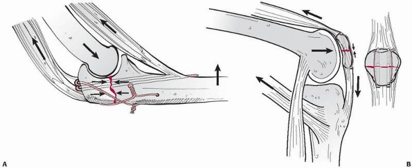 |
|
FIGURE 7-38 A. An atypical example of tension band fixation of the olecranon with two K-wires and a figure of eight tension band wiring. B.
Tension band fixation of a transverse patella fracture with a tension band wire loop. Note that the tension band device must lie eccentrically on the tensile side of the bone and that this dynamic fixation is enhanced by flexion of the joint. |
deformity. Any fixation device should therefore be applied to the
convex side of the deformity, in such a way as to act as a tension
band, which then automatically induces compression and enhances bony
union (Fig. 7-39).
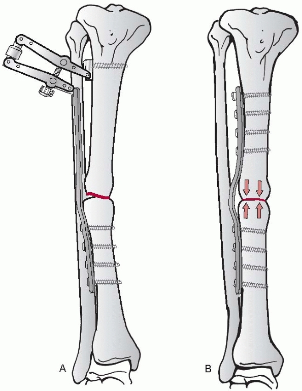 |
|
FIGURE 7-39 In mal- and nonunions with deformity (A), the plate applied to the convex or tension side of the bone acts as a tension band and compresses the bone ends (B).
|
L, Griffin D, Bhandari M, et al. Path analysis of factors for delayed
healing and nonunion in 416 operatively treated tibial shaft fractures.
Clin Orthop Relat Res 2005; 438:221-232.
R, Hehl M, Regazzoni P. LISS Tractor. Kombination des less invasive
stabilization systems (LISS) mit dem AO-Distraktor fuer distale Femur-
und proximale Tibiafrakturen. Unfallchirurg 2001;104:530-535.
JM, Torres JM, Tur C, et al. Saline wound irrigation reduces the
postoperative infection rate in guinea pigs. J Surg Res 1996;63:457-459.
F, Dahlen C, Stiletto R, et al. Technique of using the AO-femoral
distractor for femoral IM nailing. J Orthop Trauma 1994;8:315-321
M, Guyatt GH, Tong D, et al. Reamed versus nonreamed IM nailing of
lower extremity long bone fractures: a systematic overview and
meta-analysis. J Orthop Trauma 2000;14:2-9.
M, Tornetta P 3rd, Sprague S, et al. Predictors of reoperation
following operative management of fractures of the tibial shaft. J
Orthop Trauma 2003;17(5):353-361.
H, Broekhuizen T, Patka P, et al. Randomized controlled trial of single
dose antibiotic prophylaxis in surgical treatment of closed fractures:
the Dutch Trauma Trial. Lancet 1996;347:1133-1137
Orthopedic Trauma Society. Nonunion following intramedullary nailing of
the femur with and without reaming. Results of a multicenter randomized
clinical trial. J Bone Joint Surg Am 2003;85-A(11):2093-2096.
PS, Klimkiewicz JJ, Luchetti WT, et al. Impact of CT scan on treatment
plan and fracture classification of tibial plateau fractures. J Orthop
Trauma 1997;11:484-489.
LE, Augat P, Suger G, et al. Influence of size and stability of the
osteotomy gap on the success of fracture healing. J Orthop Res
1997;15(4):577-584.
CM, Christie J, McQueen MM. Closed intramedullary tibial nailing. Its
use in closed and type I open fractures. J Bone Joint Surg Br
1990;72(4):605-611.
H, Hanke C, Arens S, et al. PC Fix and local infection
resistance—influence of implant design on postoperative infection
development, clinical and experimental results. Injury 2001;32(Suppl
2):38-42.
O, Krettek C, Miclau T, et al. Minimally invasive plate osteosynthesis:
does percutaneous plating disrupt femoral blood supply less than the
traditional technique? J Orthop Trauma 1999;13(6):401-406.
R. Locking compression plate (LCP). An osteosynthesis plate based on
the dynamic compression plate and the point contact fixator (PC-Fix).
Injury 2001;32(Suppl 2): 63-66.
GM, Burgar AM. Percutaneous skeletal joysticks for closed reduction of
femoral shaft fractures during IM nailing. J Orthop Trauma
2001;15:570-571.
RB, Mendoza RM, Williams DN. Problems in the management of type III
(severe) open fractures: a new classification of type III open
fractures. J Trauma 1984;24: 742-746.
N, Hauke C, Schutz M, et al. Treatment of diaphyseal fractures of the
forearm using the Point Contact Fixator (PC-Fix): results of 387
fractures of a prospective multicentric study (PC-Fix II). Injury
2001;32(Suppl 2):B51-B62.
U, Kemper F, Hierholzer G, et al. Severely comminuted femoral shaft
fractures: treatment by bridging-plate osteosynthesis. Arch Orthop
Trauma Surg 1987;106: 327-330.
EW. Ununited fractures with special reference to gunshot injuries and
the use of bone grafting. J Bone Joint Surg Br 1918;6:203-228.
P, Matter P, Minter J. Arthroscopically assisted treatment of lateral
tibial plateau fractures in skiers: use of a cannulated reduction
system. J Orthop Trauma 1994;8: 273-281.
TM, Aksenov SA, Schemitsch EH. Cortical bone blood flow in loose- and
tight-fitting locked unreamed IM nailing: a canine segmental tibia
fracture model. J Orthop Trauma 1998;12:127-135.
MJ, Stockle U, Schutz M, et al. Stabilization of periprosthetic
fractures with angular stable internal fixation: a report of 13 cases.
Arch Orthop Trauma Surg 2006;126(2): 105-110.
I, Jaeger JH, North J, et al. L’enclouage centro-medullaire du femur et
du tibia selon la technique de Kuntscher. Interet du verrouillage du
clou. Etude experimentale. Acta Orthop Belg 1976;42(Suppl 1):29-43.
D, Citak M, Gardner MJ, et al. Navigated femoral nailing using
noninvasive registration of the contralateral intact femur to restore
anteversion. Technique and clinical use. J Orthop Trauma
2007;21(10):725-730.
C, Bolhofner BR, Mast JW, et al. Subtrochanteric fractures of the
femur. Results of treatment with the 95 degrees condylar blade-plate.
Clin Orthop Relat Res 1989;238: 122-130.
MP, Rahn BA, Frigg R, et al. Reaming versus nonreaming in medullary
nailing: interference with cortical circulation of the canine tibia.
Arch Orthop Trauma Surg 1990; 109:314-316.
K, Schellmann WD. Dynamische und statische Verriegelung des Marknagels.
Monatsschr Unfallheilkd Versicher Versorg Verkehrsmed 1972;75:568-575.
PJ, Hughes JL, Cole PA. Fixation of distal femoral fractures above
total knee arthroplasty utilizing the less invasive stabilization
system (L.I.S.S.). Injury 2001; 32(Suppl 3):SC64-SC75.
C, Miclau T, Schandelmaier P, et al. The mechanical effect of blocking
screws (“Poller screws”) in stabilizing tibia fractures with short
proximal or distal fragments after insertion of small-diameter IM
nails. J Orthop Trauma 1999;13:550-553.
C, Muller M, Miclau T. Evolution of minimally invasive plate
osteosynthesis (MIPO) in the femur. Injury 2001;32(Suppl 3):SC14-SC23.
C, Schandelmaier P, Miclau T, et al. Transarticular joint
reconstruction and indirect plate osteosynthesis for complex distal
supracondylar femoral fractures. Injury 1997;28(Suppl 1):A31-A41.
JN, Metaizeau JP, Prevot J, et al. Elastic stable IM nailing of femoral
shaft fractures in children. J Bone Joint Surg Br 1988;70:74-77.
D, Michelson JD, Ney DR, et al. Adult ankle fractures: comparison of
plain films and interactive two- and three-dimensional CT scans. AJR Am
J Roentgenol 1990;154: 1017-1023.
JA, Bain GI, Heptinstall RJ. Anatomical reduction of intra-articular
fractures of the distal radius. An arthroscopically assisted approach.
J Bone Joint Surg Br 2000;82: 79-86.
GA, Metzdorf A, Schlegel U, et al. Influence of reaming versus
nonreaming in intramedullary nailing on local infection rate:
experimental investigation in rabbits. J Trauma 1995;39(6):1123-1128.
C, Frigg R, Pfister U. Effect of flexible drive diameter and reamer
design on the increase of pressure in the medullary cavity during
reaming. Injury 1993;24(Suppl 3): S40-S47.
C, McIff T, Rahn BA, et al. Influence of the compression force on the
IM pressure development in reaming of the femoral medullary cavity.
Injury 1993;24(Suppl 3): S36-S39.
PE, Baumgart F, Kohler G. Heat-induced segmental necrosis after reaming
of one humeral and two tibial fractures with a narrow medullary canal.
Injury 1998; 29(Suppl 2):B1-10.
HJ, Tscherne H. Pathophysiology and classification of soft tissue
injuries associated with fractures. In: Tscherne H, Gotzen L, eds.
Fractures with Soft Tissue Injury. Berlin: Springer, 1984.
GD, Renaud E, Dagenais G, et al. Double-blind randomized prospective
study of the efficacy of antibiotic prophylaxis for open reduction and
internal fixation of closed ankle fractures. J Orthop Trauma
1994;8:64-66
HC, Giannoudis PV, Grimme K, et al. Effects of IM femoral fracture
fixation: what is the impact of experimental studies in regards to the
clinical knowledge? Shock 2002; 18:291-300.
SM. Evolution of the internal fixation of long bone fractures. The
scientific basis of biological internal fixation: choosing a new
balance between stability and biology. J Bone Joint Surg Br
2002;84(8):1093-1110.
SM. The concept of biological plating using the limited contact-dynamic
compression plate (LC-DCP). Scientific background, design, and
application. Injury 1991; 22(Suppl 1):1-41.
SM, Frigg R, Hehli M, et al. Lag screw. In: Ruedi TP, Murphy WM, eds.
AO Principles of Fracture Management. Stuttgart: Thieme, 2000.
SM., Klaue K., Pohler O, et al. The limited contact dynamic compression
plate (LC-DCP). Arch Orthop Trauma Surg 1990;109(6):304-310.
W, Granowski R. Das “Zespol”—osteosynthesesystem: mechanische grundlage
und klinische anwendung. Orthop Praxis 1984;9:750-758.
WM, Loftus T, Cox C, et al. Locked plates combined with minimally
invasive insertion technique for the treatment of periprosthetic
supracondylar femur fractures above a total knee arthroplasty. J Orthop
Trauma 2006;20(3):190-196.
LV, Rush HC. A reconstruction operation for a comminuted fracture of
the upper third of the ulna. Am J Surg 1937;38:332-333.
P, Krettek C, Tscherne H. Biomechanical study of nine different tibia
locking nails. J Orthop Trauma 1996;10:37-44.
KD, Zhang L, Haas NP, et al. Temporal profile of microvascular
disturbances in rat tibial periosteum following closed soft tissue
trauma. Langenbecks Arch Surg 2003;388:323-330.
EH, Kowalski MJ, Swiontkowski MF, et al. Cortical bone blood flow in
reamed and unreamed locked IM nailing: a fractured tibia model in
sheep. J Orthop Trauma 1994;8:373-382.
M, Muller M, Krettek C, et al. Minimally invasive fracture
stabilization of distal femoral fractures with the LISS: a prospective
multicenter study. Results of a clinical study with special emphasis on
difficult cases. Injury 2001;32(Suppl 3): SC48-SC54.
KM. Die elastische Plattenosteo-synthese, ihre Biomechanik, Indikation
und Technik im Vergleich zur rigiden Osteosynthese. Unfallchirurg
1996;99:816-829.
K, Runkel M, Degreif J, et al. Pathogenesis and clinical relevance of
bone marrow embolism in medullary nailing: demonstrated by
intraoperative echocardiography. Injury 1993;24(Suppl 3):S73-S81.