
One – General Principles: Basics > Principles of Treatment > 8 –
Principles of External Fixation
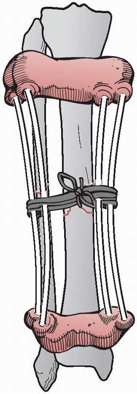
2400 years ago, when he wrote on a method to immobilize a fracture of
the tibia, at the same time allowing for the inspection of the soft
tissue injury. This was accomplished by wrapping the proximal and
distal tibia with leather wraps, “such as are worn by persons confined
for a length of time in large shackles, and they should have a
thickened coat on each side, and they would be well stuffed and fit
well, the one above the ankle, and the other below the knee.”182
“Four flexible rods made of the cornel tree, (European dogwood) of
equal length should be placed between the knee and ankle wrap. If these
things be properly contrived, they should occasion a proper and equable
extension in a straight line. And the rods are commodiously arranged on
either side of the ankle so as not to interfere with the position of
the limb; and the wound is easily examined and arranged”107,182 (Fig. 8-1).
nineteenth century with Malgaigne’s description of an ingenious
mechanism consisting of a clamp that approximated four transcutaneous
metal prongs for use in reducing and maintaining patellar fractures.
This was described in 1843, a full 12 years before the introduction of
plaster casting techniques.93,182
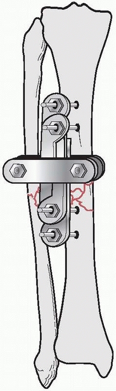
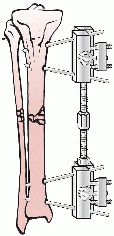
the results of nine patients treated with an external device consisting
of four screws, two of which were inserted into each fragment above and
below the fracture. The ends of the screws were fixed
together
by interlocking small plates and bolts. He did require supplemental
plaster immobilization to provide additional support to the construct (Fig. 8-2).
He treated eight nonunions and one unstable tibial shaft fracture.
Union of the fractures occurred in eight of the nine patients.179,180
His career was unfortunately cut short when he died from appendicitis.
Although he a surgeon, he would not undergo surgery for his condition
and died in Denver in 1902.
 |
|
FIGURE 8-1 Hippocrates “shackle” external device for maintaining a tibia fracture at length.
|
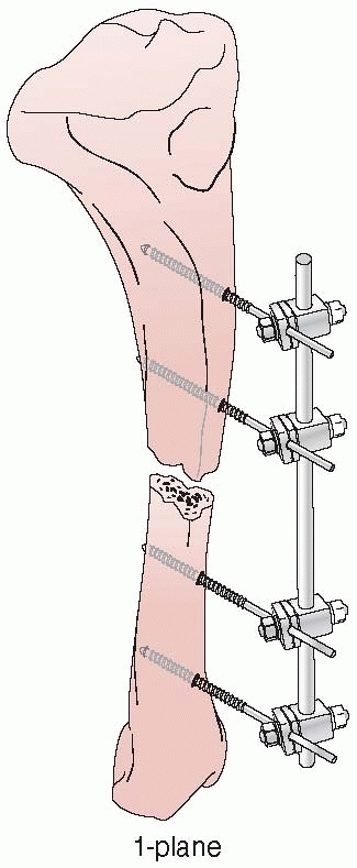
was unable to obtain a copy of Parkhill’s paper. In 1902, he expanded
external fixation further and was the first to apply a simple
unilateral frame in a systematic fashion. He recognized that the metal
pins that penetrated bone and protruded through the skin were
remarkably well tolerated and could be connected to an external clamp
device, which would allow for stabilization of these pins and thus the
bone fragments to which they were attached134 (Fig. 8-3).
Lambott’s concepts and design evolved and eventually allowed for frame
adjustments to occur, including compression and distraction at the
fracture site. In Europe, Lambott’s original concepts were expanded
significantly, and in 1938, Raul Hoffman, who was a doctor of theology
and a carpenter in his free time, devised an external fixator that
incorporated a universal ball joint connecting the external ball of the
fixator to strong pin griping clamps. This universal joint permitted
fracture reduction to occur in three planes, while the fixator was in
place. Hoffman could substitute a sliding compression-distraction bar
connecting the pin griping clamps,
and interfragmentary compression or limb length restoration could be performed108,109 (Fig. 8-4).
 |
|
FIGURE 8-2 Parkhill’s external fixator for tibia fractures.
|
 |
|
FIGURE 8-3 Lambotte’s external fixator, using simple pins and a clamp device.
|
 |
|
FIGURE 8-4 Hoffman’s multipin clamp external fixator.
|
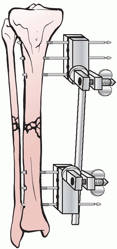
apparatus for the mechanical reduction of fractures, using
transcutaneous pins connected to metal clamps. Anderson’s early concept
called for application of through-and-through transfixion pins. This
permitted multiplanar adjustment of the fracture fragments and allowed
compression at the fracture site. Following reduction, a cast was
applied while the limb was still held by the external device.7
After the cast was applied, the external device was removed and reused
on additional patients. Later, Anderson extended this concept and
designed an entire external system that connected transcutaneous pins
to bars, eliminating the need for a plaster cast93 (Fig. 8-5).
management for use in his veterinary practice, which permitted
stabilization of fractures and allowed the independent reduction of
fracture fragments to occur in three planes.93,182
Stader’s work was observed by surgeons from Bellevue Hospital in New
York City. They persuaded him to adapt his fixator for use in humans,
and thus the Stader device was refined and enlarged for use in human
long bones. In 1942, Lewis and Briedenbach reported their experience
with this device for treating 20 patients with fractures of long bones
at Bellevue Hospital. They were encouraged by the frame’s ability to
achieve excellent alignment and early ambulation without the need for
adjunctive casting.144 (Fig. 8-6).
They were the first to describe the technique of placing pins as far
from the fracture as possible and avoiding pins placed near the site of
fracture. This was done to improve the fixator’s ability to gradually
reduce a malaligned extremity by adjusting the device. They thought
that a wide pin spread increased the overall mechanical stability of
the construct. They
also
were one of the first investigators, along with Schanz, Riedel, and
Anderson, to point out the advantages of inserting the fixation pins at
an angle to each other (not parallel) as a means of firmer control over
the bone fragments.144,182
 |
|
FIGURE 8-5 Anderson device with through-and-through transfixion pins.
|
 |
|
FIGURE 8-6 The Stader device.
|
States during World War II was documented by Shaar and Kreuz with their
use of the Stader splint.210,211
Although there were some favorable reports on the use of external
fixation techniques and their use at base hospitals, experience showed
that the techniques were too specialized and time consuming for use in
an active combat zone. Because of the high incidence of significant
complications associated with external fixation, this technique fell
into general disfavor because these complications were by and large
attributed to the external fixation device and not necessarily to the
problems of treating high-energy open fractures.99 This resulted in a directive issued to military surgeons of the U.S. Armed Forces to discontinue the use of external fixation.93
Committee on Fracture and Trauma Surgery of the American Academy of
Orthopaedic Surgeons (AAOS) to investigate the efficacy and indications
for external fixation in clinical fracture management. The study was
based on 3082 questionnaires sent to practicing clinicians who were
members of the American Academy of Orthopaedic Surgeons (AAOS), the
American Association of Surgery and Trauma, and the Iowa Medical
Association. Only 395 replies were analyzed by the committee.
Twenty-eight percent of the respondents thought that external skeletal
fixation had a definite place for fracture management, while 29.4%
thought that external fixation was not inadvisable except in select
rare instances.118 Over 43% of
respondents had used external fixation at one time but had abandoned it
completely at the time of the survey. Based on the results of the
survey and concerns that practitioners had with the potential
mechanical difficulty associated with these frames, as well as the
prospect of converting a closed fracture to an open fracture, the
committee concluded that any physicians who contemplated the use of
external skeletal fixation required special training under the
supervision of a surgeon who had treated at least 200 cases by this
method.93 As a consequence, by 1950
the majority of American surgeons were not using this modality. From
1950 to 1970, external fixators were generally unpopular with American
orthopedists, although pins and plaster were still widely used for
wrist and tibial fractures.
subject the various assemblies of the external fixator frames to
mechanical testing. Vidal used Hoffman’s equipment but designed a
quadrilateral frame to provide rigid stabilization of complex fracture
problems. His biomechanical studies determined that the quadrilateral
configuration was quite stable.93,227
original concept of a unilateral frame using a single connecting bar
and half-pins. His extensive clinical experience with a half-pin frame
documented the success of this device when treating several large
series of fracture problems.35,36
1970s demonstrated that the use of external fixation could not only
treat fractures but also be extended to the treatment of
pseudoarthrosis, as well as infections and arthrodesis.
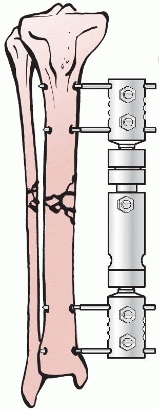
Axial Fixator,” and Gotzen, the “Monofixator.” These were simple four
pin frames with large pin clusters positioned at either ends of the
bone. These were then connected to each other by a largediameter
telescoping tubular rod (Fig. 8-7). This
innovation allowed the frames to be more patient friendly compared with
the complex fixators of Vidal-Adrey. These frames would promote axial
loading with full weight bearing and would accentuate micromotion and
dynamization at the fracture site to enhance healing.
 |
|
FIGURE 8-7 Large body monotube external fixator.
|
which was emanating from Europe in the early 1970s, along with the
promising clinical results from European centers, stimulated renewed
interest in the use of these techniques in North America. This also
coincided with the publication of the second edition of the A/O Manual in 1977.106
It was at this time that external fixation was recommended for the
treatment of acute open fractures. Simultaneous with the
recommendations, the second A/O Manual
showed a new tubular monolateral external fixation system. The tubular
system of the ASIF gained wide acceptance very rapidly, because of
improved pin design and frame biomechanics, as well as precise
indications for their use. These factors contributed to many North
American surgeons revisiting and adopting this technique, as well as
reporting good clinical results (Fig. 8-8).
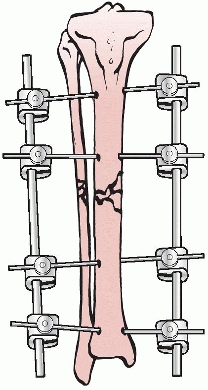
continued to remain viable in Russia following World War II. Instead of
concentrating on half-pin- and monolateral-type configurations, their
techniques focused on the use of very thin transfixion wires, which
were tensioned to maintain bone segment fixation. In the early 1950s,
Gavril Abramovitch Ilizarov developed a circular fixator, which
permitted surgeons to stabilize bone fragments but also made
three-dimensional reconstructions possible.
 |
|
FIGURE 8-8
The “simple monolateral” multicomponent external fixation system that helped renew interest in contemporary external fixation techniques. |
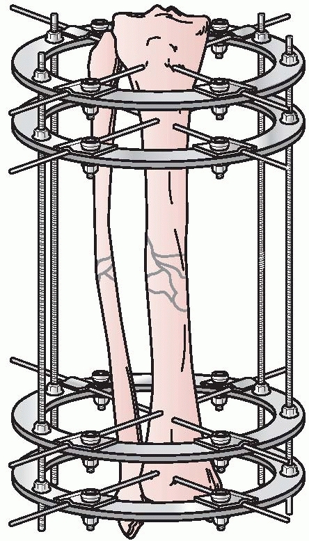
could be individually manipulated to provide for three planes of
correction, similar to the concepts pioneered by Hoffman, Bernie, and
Vidal. This ability to achieve precise ring positioning resulted in
significant flexibility of the device1,112 (Fig. 8-9).
patients treated with distraction arthroplasty at the knee and elbow
using small transfixion wires attached to ring fixators. Their work
went largely unnoticed in North America even though it was published in
the American Journal of Bone and Joint Surgery.230
apparatus and designed a circular-type fixator. Instead of using thin
tensioned wires as with the Russian device, he designed a fixator
configuration, which allowed for significant pin separation, deviation
of pins at various angles, and a semicircular configuration. He
determined that fracture site stability could be increased using these
circular configuration concepts.80,93
quite cumbersome and complex compared with the more straightforward
A/O- and Hoffman-type fixators, Kroner in 1978 refined and modified the
Russian devices by using plastic components and transfixion pins in
place of the thin wires used with the Ilizarov technique.93,112
of Kurgan in Siberia. In 1980, the technique was introduced to western
Europe thanks to the innovative1
treatment of world famous Italian explorer Carlo Mauri. Mauri traveled
exclusively to Russia for this technique and was successfully treated
for an infected pseudarthrosis of the tibia by Ilizarov. Through the
friendship established by Mauri with Prof. Ilizarov, the technique was
brought back to Italy under the guidance of Prof. Roberto Cattaneoto
and his associates, Drs. Villa, Catagni, and Tentori. They began the
first Western clinical trials with transosseous osteosynthesis using
Ilizarov’s fixator in Lecco, Italy, in 1981.1,112
 |
|
FIGURE 8-9 Ilizarov’s circular fixator using small tensioned wires attached to individual rings.
|
under different leadership in the 1980s, the possibilities of the
Ilizarov method and biology that had previously been unrecognized in
the West became more apparent. These techniques were presented at
various orthopaedic meetings in Italy and other centers in western
Europe in the early 1980s.1,93,112
Frankel, James Aronson, Dror Paley, and Stewart Green, were exposed to
Ilizarov’s work and determined that the methodology applied to
difficult contemporary orthopaedic problems had vast potential and
began clinical applications in the mid 1980s.1,112
In 1989, Green, who had significant expertise in treating nonunions and
osteomyelitis with external fixation techniques, was entrusted by
Ilizarov to translate his original basic science work into English.
This was published in Clinical Orthopaedics and Related Research in 1989.112,113,114
cadre of American surgeons in the late 1980s. This technique today has
become widely accepted for complex problems in traumatology,
reconstructive surgery, and limb lengthening. In an effort to simplify
and apply these techniques to traumatology, the tensioned ring concept
was married to the unilateral fixator and the hybrid external fixator
was developed to address periarticular injuries with all the advantages
of tensioned wires, while limiting the disadvantages of tethering large
musculotendinous units with through and through transfixion wire
constructs1,96 (Fig. 8-10).
fracture reductions have been developed by Charles Taylor and others to
correct complex deformities through the use of simple ring constructs
using half-pin fixation. These “hexapod” fixators are ring fixators
with the rings interconnected and manipulated by a system of adjustable
struts, which allow for six axis correction of bone fragments (Fig. 8-11).
The development of this concept, as well as the ability to interface
deformity correction with web-based software, has continued the
progression and advancement of contemporary external fixation
techniques.
 |
|
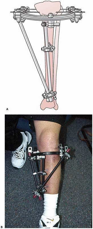
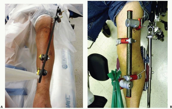
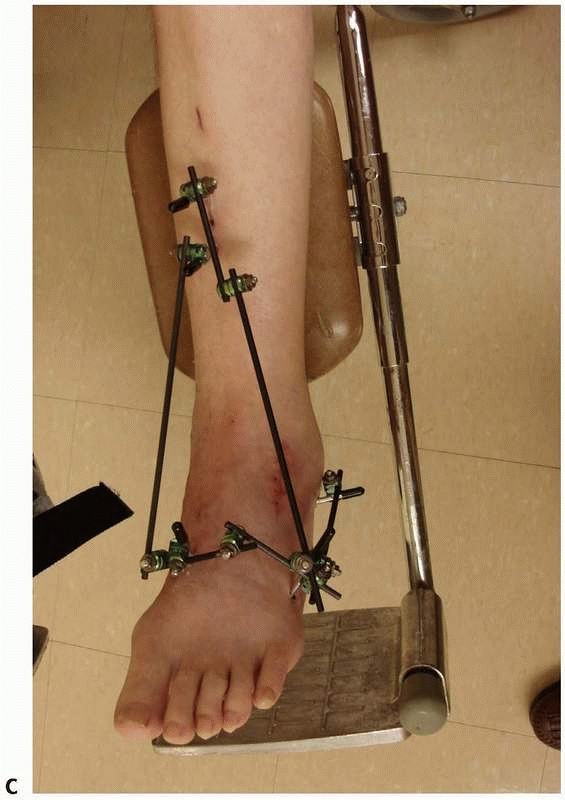
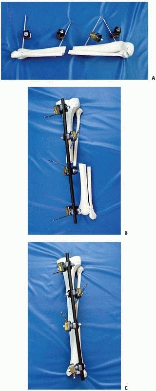
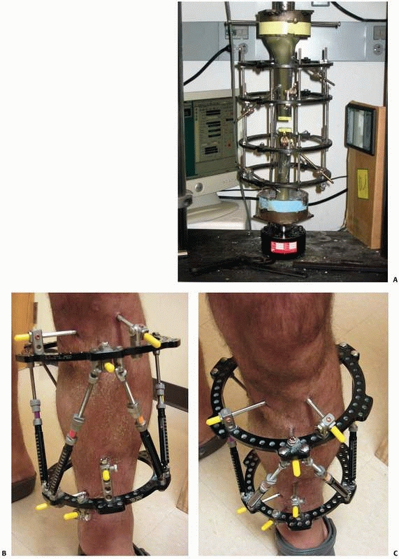
FIGURE 8-10 A.
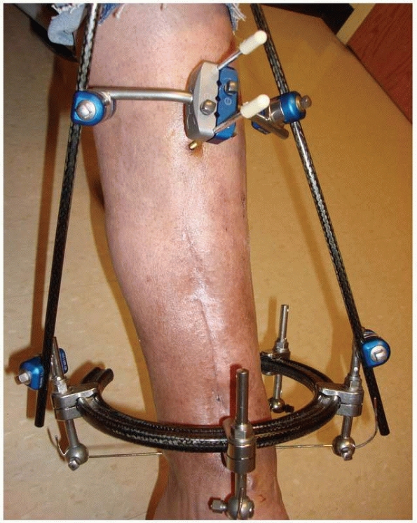
An early version of a hybrid external fixator that combines periarticular tensioned wires and diaphyseal half-pin configurations. B. Clinical picture of the same hybrid frame on a patient with a tibial plateau fracture. |
 |
|
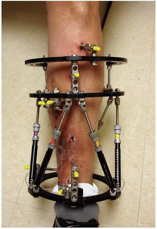
FIGURE 8-11
Hexapod external fixator (Taylor Spatial Frame), with multiple oblique connecting struts through which the limb segments can be manipulated for simultaneous correction of multiple deformities. |
categorized according to the type of bone anchorage used. This is
accomplished by using either large threaded pins, which are screwed
into the bone, or by drilling small-diameter transfixion wires through
the bone and then placing the wires under tension to maintain bone
fragment position.
through the use of longitudinal bars or circular rings. Thus, the
distinction is made between monolateral external fixation (longitudinal
connecting bars) and circular external fixation (wires and/or pins
connecting to rings). Circular fixation may use either threaded pins or
small tensioned wires to attach the bone to
the
frame. Monolateral fixation is accomplished using variousdiameter
threaded pins; however, these may occasionally involve the use of
centrally threaded through-and-through transfixion pins.
using various sizes of terminally threaded pins. The half-pins have a
wide range of diameter ranging from 2 mm to 6 mm with all intermediate
sizes available. Additionally, there are largediameter pins with
threads in the midportion of the device (i.e., centrally threaded pins)
for use in transfixion-type constructs (i.e., Hoffman/Vidal
configurations) (Fig. 8-12, A-E).
 |
|
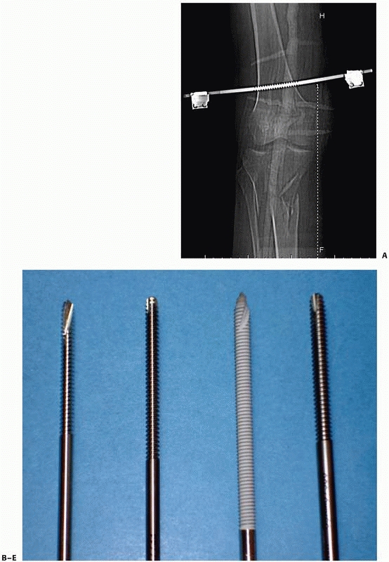
FIGURE 8-12 A.
Large centrally threaded Schanz pin placed as a transfixion pin in a temporary knee-spanning external fixator. Pins with larger thread diameter are suitable for cancellous bone insertion as in this case. B. Multiple pin types (from left) with 5-mm self-tapping predrilled pins with a short thread length. The small pitch angle and narrow thread diameter of this pin are ideal for application in cortical bone. C. A 5-mm self-tapping predrilled pin with long threads. D. A 6-mm hydroxyapatite self-drilling pin; note self-drilling tip. Hydroxyapatite-coated pins improve the pin-bone interface by encouraging direct bone apposition and ingrowth. E. A 6-mm self-tapping predrilled titanium pin. |
fixation are numerous. The actual biomechanical function that a
monolateral frame will perform is dependent on the placement of the
pins and orientation of the connecting bars applied. These factors, as
well the inherent skeletal pathology treated, combine
to
impart a specific biomechanical function to the fixation construct. The
ability to neutralize deforming forces is the most common mechanical
principle exploited with external fixation. This is especially true for
fresh fractures accompanied by severe soft tissue damage. The use of
monolateral fixation for the stabilization of fresh fractures is used
emergently as a way of dealing with soft tissue compromise in the
immediate posttrauma/postoperative period.78
Following resolution of the soft tissue injury, secondary procedures
such as bone grafting or delayed internal fixation are commonly
considered. The primary function of fixators used in this way is to
provide relative stability to maintain the temporary fracture reduction
at length to avoid collapse of the fracture construct. It should be
noted, however, that this type of stabilization is reasonably
“flexible” as it is nearly impossible to achieve absolute rigidity to
achieve primary bone healing using monolateral or less flexible
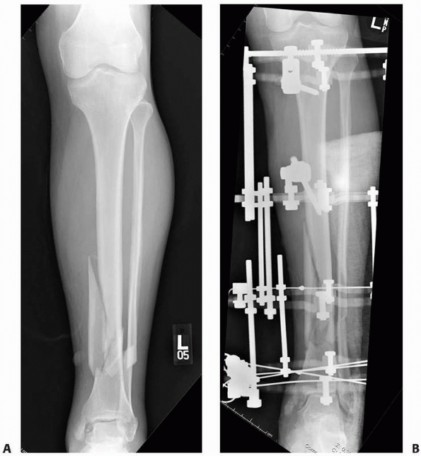
external fixation (Fig. 8-13).
 |
|
FIGURE 8-13
Simple “spanning” fixator with a transfixion pin above and below the midtibial injury. This maintains the reduction but is not “rigid” and requires additional temporary splinting. |
to bring areas of metaphyseal or metadiaphyseal bone into close contact
through the use of compression techniques. This may be useful in
arthrodesis, osteotomy, or nonunion repair175 (Fig. 8-14).
Similarly, distraction forces can also be applied across pin groups to
effect deformity correction, intercalary bone transport, or limb
lengthening.
type, the most important factors regarding the longevity and
performance of the frame are the strength and competency of the
pin-bone interface. Pin loosening with subsequent pin sepsis continues
to be problematic. There are many biomechanical factors, which have
been evaluated for the prevention of pin tract problems. All pin types
and designs are based on these concepts.14,22,59,90,92,101
-
Pin geometry and thread design
-
Pin biomaterials and biocompatibility
-
Pin insertion techniques
-
Pin bone stresses
and the type of cutting head have a significant effect on the holding
power of screws. Screw diameter is crucial in determining the stiffness
of the frame, as well as in determining the risk of stress fracture at
the pin site entry portal. The bending stiffness of the screw increases
as a function of the pin’s radius raised to the fourth power (S = r4).
Calculations have determined that in adult bone, a pin diameter of 6 mm
is the maximum that can be used to achieve a stable implant without
suffering the consequences of stress fracture through the pinhole
itself.41,185,207
In addition to the variable diameter of the pin, the screw thread may
have differing pitch angle and pitch height. The screw design must make
allowances for the quality and location of bone to which the screw is
applied. Pins, which have a small pitch height and low pitch angle, are
usually applied in regions of dense cortical bone, such as femoral and
tibial diaphysis.
and the diameter of the thread increase, the area captured by each
individual thread is broader and more likely to be applied in
cancellous bone rather than in hard cortical bone. Conical pins have
been designed so that the threads taper and increase in diameter from
the tip of the pin to the shaft. This allows the pins to increase their
purchase, theoretically by cutting a new larger path in the bone with
each advance of the pin. This conical taper also produces a gradual
increase in radial preload and thus the screw-bone contact is
optimized. Micromotion typical of a straight cylindrical screw is
avoided.136,164,166
Finite element analyses of the near pin-bone interface cortex revealed
stress values that were significantly increased by the use of deep
threads and by the use of stainless steel as opposed to titanium pins.
Titanium has a much a lower modulus of elasticity. Because of the
better biocompatibility afforded with titanium and titanium alloys,
there are some investigators who prefer the lower pin-bone interface
stresses, as well as the better biocompatibility when using titanium,
because they believe there is a lower rate of pin sepsis. This may be
due to many factors, including an actual bone ingrowth phenomenon seen
at the pin-bone interface.158,160,164
In a prospective trial, 80 patients (320 pins) with unstable distal
radius fractures were treated with external wrist fixators. The
external fixator pins were either stainless steel or titanium alloy.
The rate of premature fixator removal because of severe pin tract
infection (5% versus 0%) and the rate of pin loosening (10% versus 5%)
were higher in the stainless steel pin group. The authors concluded
that the use of titanium alloy external fixator pins in distal radial
fractures yields a trend of reduced pin-related complications and
significantly reduced pain levels compared with the stainless steel pin
fixators.184
pin-bone interface fixation, coating the pins with hydroxyapatite (HA)
has been shown to be one of the most effective.20,38,147
the strength of fixation at the pin-bone interface, which corresponded
to a lower rate of pin tract infection.163
The HA coating provides a significant increase in direct bone
apposition with a decrease in the fibrous tissue interposition at the
pin-one interface. These advantages provided by HA coating appear to be
clinically more relevant when these pins are used in cancellous bone
rather than in cortical bone38,161,162 (see Fig. 8-12, B-E). In subsequent studies, HA coating on fixator pins has been
shown to be more important for optimal pin fixation than the particular
combination of design parameters used in each pin type (i.e., thread
pitch, thread configuration, tapered, etc.).159
 |
|
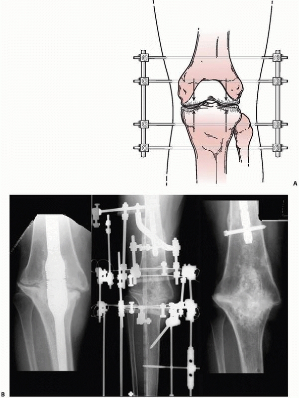
FIGURE 8-14 A. A simple “compression” monolateral system constructed to achieve arthrodesis of the knee. B.
Complex ring external fixator to effect similar compression forces for an infected knee fusion intramedullary nail. Solid arthrodesis was achieved following frame removal, débridement, and compression treatment. |
pin loosening. Radial preload is a concept that prestresses the
pin-bone interface in a circumferential fashion rather than in just one
direction.27,67
greater thread diameter versus the core diameter of the pilot hole. The
small mismatch increases insertion and removal torque, with a decrease
in signs of clinical loosening. There is a point at which insertion of
pins with a mismatch of greater than 0.4 mm can result in significant
microscopic structural damage to the bone surrounding the pin. High
degrees of radial preload or large pilot hole thread diameter mismatch
will exceed the elastic limit of cortical bone, with subsequent stress
fracture. Thus, the use of oversize pins producing excessive radial
preloads must be questioned.27,86,121
pin-bone interface. The pins typically come in two types: predrilled
pins and self-drilling pins (see Fig. 12B-E). Predrilled pins, by their
name, require a drill to be used to produce a pilot hole prior to insertion of the pin. The pilot hole has a root diameter equal to or somewhat less than the core diameter of the pin itself.112,207 As a better pilot hole is drilled with a precise cutting tip, the radial preload is also affected, which will also affect the
overall pullout strength. The advantage of predrilling using very sharp
drills for pilot holes is that it minimizes the risk of thermal
necrosis and subsequent bone damage.67 The use of self-tapping cortical pins allows each thread to purchase bone as the pin is slowly advanced by hand50,59 (see Fig. 8-12).
under power into the bone to engage the threads in cortical or
cancellous bone. There is some concern that when using self-drilling
pins, the near cortex thread purchase may be stripped as the drill tip
of the pin engages the far cortex. As the drill tip on the pin spins to
cut the far cortex, the newly purchased bone in the near threads is
stripped and the pin stability is compromised. Some studies indicate a
25% reduction in bone purchase of self-drilling, self-tapping pins
compared with that of predrilled pins.8
This is also accompanied by a marked increase in depth of insertion
required to achieve a similar pin purchase or pin “feel,” when a
self-drilling pin has a long, sharp-tipped drilling portion adjacent to
the actual threads.150 To have both
cortices engaged with full threads, the pin must be advanced through
the far cortex enough to capture the fully threaded portion of the pin
and avoid the tapered drill tip. This may leave the tip of the pin
“proud” for 2 to 3 mm, which may be problematic in certain anatomic
areas where neurovascular structures are directly adjacent to the bone (Fig. 8-15).
pin means that less of the pin tip needs to project through the far
cortex before a firm grip is achieved on the bone. The flutes for
tapping the bone run obliquely back down the shaft of the pin. The
helical or spiral nature of the flutes steers the bone debris back
along the pins and out into the soft tissue. The efficient removal of
this bone is mandatory to avoid compacting and jamming the cutting
flutes with bone debris and thus compromising their cutting ability,
increasing the heat of insertion.86
The potential disadvantages of self-drilling pins are, therefore,
increased heat of insertion; increased microfracture at both cortices,
specifically at the near cortex with increased bone resorption; and
subsequent decreased pull-out strength with decreased insertion and
extraction torque.50,164
Studies have noted elevations of temperature on heat of insertion with
a direct drill technique, where temperatures in excess of 55° C can
occur during insertion of self-drilling pins.153
The complication of thermal necrosis with secondary loosening caused by
the resorption of nonviable bone is a real theoretic concern (Fig. 8-16).
Clinically, there does not appear to be any increased incidence of pin
tract infection or other pin-associated complications reported with the
use of self-drilling pins.206
 |
|
FIGURE 8-15
Pin insertion technique should include the evaluation of the far cortex-pin interface to determine the appropriate depth pin penetration. Excessive penetration can result in potential neurovascular injury if self-drilling pins “pull” the pin too far in order to gain adequate thread purchase. These pins are placed correctly and do not protrude excessively beyond the far cortex. |
that come with individual separate components (i.e., separate bars,
attachable pin bar clamps, bar-to-bar clamps, and separate Schanz
pins). These “simple monolateral” frames allow for a wide range of
flexibility with “build-up” or “build-down” capabilities. These
components are available with various diameter connection bars as well
as multiple clamp sizes and pin clamp configurations. These often are
also available in “mini” configurations for stabilization of smaller
areas of involvement such as for the wrist and hand as well as foot and
ankle involvement. This allows the surgeon to apply a frame specific to
the clinical and biomechanical needs of the pathology addressed (Fig. 8-17).
fixator, which comes preassembled with a multipin clamp at each end of
a long rigid tubular body. The telescoping tube will allow for axial
compression or distraction of this “monotube”-type fixator. “Simple
monolateral fixators” have the distinct advantage of allowing
individual pins to be placed at different angles and varying
obliquities while still connecting to the bar. This is helpful when
altering the pin position relative to areas of soft tissue compromise.
The advantage of the monotube-type fixator is its simplicity. Pin
placement is predetermined by the multipin clamps. Loosening the
universal articulations between the body and the clamps allows these
frames to be easily manipulated to reduce a fracture. Similarly,
compression (dynamization) or distraction can be accomplished by a
simple adjustment of the monotube body (see Fig. 8-7).
the concept of a simple “four-pin frame.” Pin number, pin separation,
and pin
proximity
to the fracture site, as well as bone bar distance and the diameter of
the pins and connecting bars, all influence the final mechanical
stability of the external fixator frame (Fig. 8-18).
 |
|
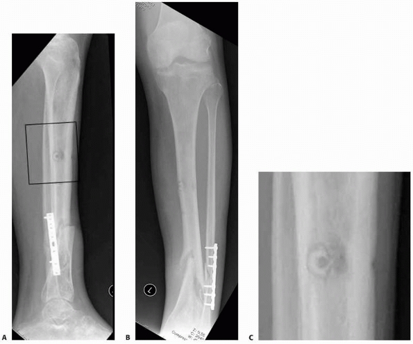
FIGURE 8-16 A,B.
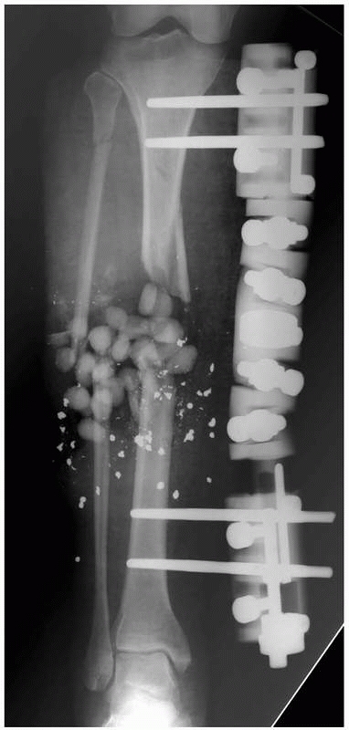
Nonunion with varus deformity following failure of hybrid external fixation. Self-drilling pins used in the diaphysis resulted in a ring sequestrum at proximal pin site (black box). C. Sclerotic bone (dead) at old pin location, with circumferential lucency characteristic of ring sequestrum. This complication required excision of the infected sequestrum. |
 |
|
FIGURE 8-17 A,B.
Two similar monolateral external fixators both used to span knee dislocations. Note similar components: separate pin clamps and bars. (A. Jet-X monolateral fixator, B. Hoffman Monotube fixator.) |
 |
|
FIGURE 8-17 (continued) C. “Mini” monolateral frame used to span an ankle (Mini-Hoffman ex-fix).
|
placement of pins prior to the application of the connecting bars. This
permits the surgeon to place pins out of the zone compromised skin or
away from the fracture hematoma. The versatility of contemporary
pin/bar clamps is based on multiple degrees of freedom built into the
clamp that allow a single bar to attach to all four clamps while still
retaining the ability to reduce the fracture. The pins do not have to
be placed in precise alignment as was required by earlier monolateral
frame designs (Fig. 8-19). If aligned pin placement positioning is contraindicated because of
soft tissue or other concerns, the fractures can still be reduced by
simply adding additional connecting bars and using the proximal and
distal pin groupings as reduction handles; once reduction is achieved,
the bar-to-bar connecting clamp is tightened and reduction is
maintained (Fig. 8-20).
 |
|
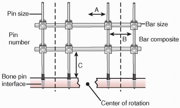
FIGURE 8-18
Factors affecting the stability of monolateral external fixation include pin distance from fracture site, pin separation, bone-bar distance, connecting bar size and composition, pin diameter, pin number, and pin-bone interface. A. Pin to center of rotation; B. pin separation; C. bone-bar distance. |
 |
|
FIGURE 8-19 A. Versatility of a monolateral frame is demonstrated. Pins can be positioned out of plane with respect to each other. B. A solitary connecting bar is able to connect to all pin bar clamps. C. Reduction can be accomplished by manipulating each limb segment and then tightening the clamps to lock the reduction in place.
|
 |
|
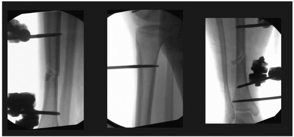
FIGURE 8-20 A. Tibia fracture is grossly reduced and two pins each placed above and below the fracture. B.
Each two-pin segment is connected with a single bar. The reduction is fine tuned and the two bars are connected to each other to lock in the reduction. C. Final postreduction radiograph demonstrating two pins in each limb segment |
maximizing pin separation distance on each side of the fracture
component as well as the number of pins used. In the case of a four-pin
system, the use of two pins on each limb segment with maximal pin
spread minimizing the bone-correcting bar distance also increases
stability172 (see Fig. 8-18).
Behrens demonstrated unilateral configurations with stiffness
characteristics similar to those of the most rigid one- and two-plane
bilateral constructs that are easily built using the “four-pin frame”
as a basic building block22,23,24 (Fig. 8-19).
Mechanically, most effective were the “delta” plane configurations,
when two simple four-pin fixators are applied at 90-degree angles to
each other and connected (Fig. 8-21). However,
single and double stacked bar anterior four-pin frames have the best
combination of clinical and mechanical features (Fig. 8-22).
The complex delta frames allow for gradual frame build-down on a
rational basis to slowly transfer more load to the bone. This stepwise
frame reduction leads from the most rigid unilateral constructs to
frames that allow the most complete force transmission across the
fracture site while still providing adequate protection against
sagittal bending movements.22,23,24 Studies have shown that a unilateral biplanar delta frame without transfixion pins can be
set up with an overall rigidity as good as that of a bilateral transfixion-type device.221
 |
|
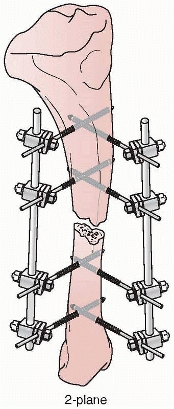
FIGURE 8-21 A delta configuration is composed of two “simple” four-pin frames connected at 90 degrees to each other.
|
 |
|
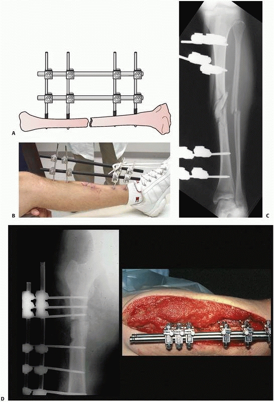
FIGURE 8-22 A. Stability of a “simple” four-pin frame can be increased by adding a second connecting bar. A “double-stacked” frame. B.
The bone-connecting bar distance was increased to avoid soft tissue impingement on the bars. Because of the increased distance to the bone an additional connecting bar was added to increase the stability of the frame. C. Reduction maintained with “simple” four-pin double stack frame. Early consolidation is noted in this comminuted open fracture. D. Infected femur fracture with severe soft tissue injury and bone loss required additional pins, and a double stack frame to achieve stability was necessary to treat this injury. |
implant stability decreases. This is clinically significant when
dealing with patients who present with wide areas of soft tissue
compromise, which may preclude the ability to place the connecting bar
close to the subcutaneous border of the bone. To counteract this, a
standard four-pin fixator should be altered to increase the number of
pins applied in each fracture segment31 (Fig. 8-22).
demonstrated that carbon fiber bars were approximately 15% stiffer than
stainless steel tubes and that the external fixator with carbon fiber
bars achieved 85% of the fixation stiffness compared with that achieved
with stainless steel tubes. They thought that the loss of stiffness of
the external fixator construct was likely due to the clamps being less
effective in connecting the carbon fiber rods to the pins.
the fixator body and the clamp or between the fixator clamp and the
Schanz pins. Insufficient holding strength on a pin by a clamp may
result in a decrease in the overall fixation rigidity, as well as
increased motion and cortical bone reaction at the pin-bone interface.14
Cyclic loading of external fixators has been shown to loosen the
tightened screws in the pin clamps. Thus, one needs to be aware of the
mechanical yield characteristics of the clamps, bars, and pins
throughout the course of treatment.68
loosening of pin-to-bar and bar-to-bar connections, the clinical
practice of regular tightening of the device during the course of
treatment should be routine.68,101,250
in a distinctly different way compared with the simpler monolateral
fixators. Most monotube fixators have fixed location for their pins
mounted in pin clusters. These are connected to the body, and thus the
ability to vary pin location is substantially less compared with simple
monolateral fixators. Because the pin clusters are fixed at either end
of the monotube body, the ability to maximize pin spread in relation to
the fracture site is limited by the monotype body’s length. There is
little variability to lower the large monotube connection bar closer to
the bone in an effort to increase stability. These frames are very
stable and accomplish their inherent rigidity by having a
large-diameter monotube connecting body, which are 3 to 4 times the
diameter of the simpler monolateral connecting bars. Because of the
large body configuration, these devices offer higher bending stiffness,
as well as equal torsional stiffness and variable axial stiffness
compared with standard Hoffman-Vidal quadrilateral frames with
transfixion pins31,44,105,117,119 (Fig. 8-23).
the large fixator bodies to their respective pin clamp configurations.
There has been concern about the ability to achieve stability due to
the ball locking mechanism. Chao and Hein44
determined that the ball joint locking cam and fixation screw clamp
required periodic tightening during clinical application to prevent
loss of frame stiffness under repetitive loading. However, frank
clinical failure with these types of ball joint devices has not been
demonstrated.12,44,105
 |
|
FIGURE 8-23 Large pin “monotube” fixator. Device has fixed proximal and distal pin clamps and a large telescoping body.
|
constrained pin clamp may result in the diminution of the overall
construct rigidity, as well as pin movement at the pin-bone interface.
This is a distinct disadvantage compared with the single component
simple monolateral frames where each pin has its own pin-bone clamp.12
When using monotube fixators, the use of six pins increased torsional
rigidity, but this configuration fails at lower bending loads compared
with the four-pin configuration, reflecting the uneven holding strength
of the pin clamp on three pins.12
plane of the pins and is minimal at right angles to this plane. Thus, a
simple four-pin frame placed along the anterior border of the tibia
will resist the anterior and posterior forces generated with normal
stride, while this frame is weakest in mediolateral bending.221,224,248
The biomechanical advantage of adding an additional two to four pins
perpendicular (90 degrees) to the anterior pins is that it increases
the mediolateral bending forces as well (delta configuration) (see Fig. 8-21).
the remaining pins, this decreases the overall strength of the
construct in the primary plane of the pins; however, this would be
compensated for by increasing the strength of the construct in
the plane at right angles.22,23,213 Thus, overall frame rigidity would be improved.
 |
|
FIGURE 8-24
Frames with nonlinear pin placement neutralize forces similar to the normal forces developed in a tibia. This frame demonstrates pins out of plane to each in the transverse and sagittal orientations. The 6-mm hydroxyapatite-coated pins were used, which gives this simple frame very stable mechanics requiring only three pins on each side of the fracture line. |
were placed at 60 degrees to each other and offered substantial
advantages. With only a 10-degree separation between the pin angles,
displacement and response to torsional stress are reduced by 97%. This
increase in torsional rigidity occurs up until about 30 degrees of pin
divergence angle, at which time torsional displacement has all but
stopped. The effects on compressive forces are much less. When fixator
pins are spread out, the fixator was 91% stronger for resisting angular
displacements and torsion compared with the traditional monolateral
orientation.213 A rigid frame
configuration is not generally perceived as undesirable, but far
preferable to merely reducing rigidity in all planes is the production
of a frame, which more closely mimics the biomechanics of normal bone.
An external fixator, which allows an offset pin angle of 60 degrees,
demonstrates the ability to equalize forces in the sagittal and coronal
planes, providing mechanical stimuli much closer to those normally
encountered in the sagittal and coronal planes45,157,172,204,212 (Fig. 8-24).
pin placement as a way to achieve maximal fracture stability with
relative frame simplicity.* A simplified two-ring circular
frame using only three 6-mm half-pins has been shown to increase
circular frame stability compared with more complex ring constructs.
The pins for these simple frames were applied at divergent angles of at
least 60 degrees to the perpendicular. These divergent 6-mm half-pin
frames demonstrated similar mechanical performance compared with
standardized multiple tensioned wire and 5-mm half-pin frames in terms
of axial micromotion and angular deflection.137
Based on the mechanical performance of these simplified divergent
half-pin frames, surgeons can now reliably improve frame stability by
simply placing pins out of plane to the long axis of the bone (i.e.,
not perpendicular to the long axis) (Fig. 8-25).
comminuted fractures or in fractures with significant fracture
obliquity and increased shear stresses. Standard half-pin application
with pins placed perpendicular to the long axis of the bone fails to
oppose the shear force vector directly, because the pins are placed
oblique to the shear force vector, and thus it does not neutralize the
cantilever forces induced by this standard pin insertion angle.
fracture line and thus in direct opposition to the shear force vector,
the shear force is actively converted into one of compression
manifesting a dynamic stabilization of the fracture edges (Fig. 8-26). In this way, compression is dependent
on axial load, and the shear phenomenon is dramatically reduced,
thereby yielding nearly zero shear. For fracture obliquities less than
or equal to 30 degrees, there is inherent stability such that standard
modes of fixation can be utilized without undue concern.106,157
However, at fracture obliquities greater than 30 degrees, one must
respect the inherent shear present with axial loading at the fracture
ends. Added steps should therefore be considered to help minimize this
shear component, such as the application of the steerage pin concept.
At fracture obliquities greater than 60 degrees, shear is a dominating
force and one must be aware that even with steerage pins, the forces
may be extreme. Frames should be modified to perform strictly as a
neutralization device as interfragmentary compression will be difficult
to achieve even with the most complex devices106 (Fig. 8-26).
be applied in a uniplanar fashion, minimizing the transfixion of soft
tissues. The ring-type systems have the disadvantage of
transfixion-type wires tethering soft tissues, as the wires pass from
one side of the limb to the other.93,112
Because of the smaller wire diameter, the trauma to the soft tissue and
bony reaction and intolerance to the wires are minimized. Large pin
monolateral fixators rely on stiff pins for frame stability. Upon
loading, these pins act as cantilevers and do produce eccentric loading
characteristics. Shear forces are regarded to be inhibitory to fracture
healing and bone formation, which may be accentuated with certain types
of monolateral half-pin stabilization, especially when pins are all in
line.10,11,13,19,43,178,251
Thus, the advantages of having half-pins placed out of plane. Circular
or semicircular fixators allow for multiple planes of fixation, which
produces frame behavior largely eliminating the harmful effects of
cantilever loading and shear forces, yet accentuating axial micromotion
and dynamization.80,145,154,172,186,248
 |
|
FIGURE 8-25 A.
Oblique (out of plane) pin testing construct that confirms oblique orientation of pins allows for fewer pins to be used with no decline in relative fixator stability. B,C. “Simple” construct with only 3- to 6-mm pins above and below the nonunion. All pins were placed out of plane to each other to affect larger pin spread and confer stability. |
 |
|
FIGURE 8-26
Steerage pin experimental set up demonstrating pins placed parallel to the major fracture line, dramatically reducing the shear forces and accentuating compressive forces with axial weight bearing. (Courtesy of David Lowenberg, MD.) |
rods and rings to which the small-diameter tensioned wires are
attached. Alternatively, the bone fragments may be attached to the
rings by half-pins. The connecting rods may incorporate universal
joints, which give these frames their ability to produce gradual
multiplanar angular and axial adjustments.
be manipulated to affect an increase in the stability of the ring
fixation construct:
-
Increase wire diameter
-
Increase wire tension
-
Increase pin crossing angle to approach 90 degrees
-
Decrease ring size (distance of ring to bone)
-
Increase number of wires
-
Use of olive wires/drop wires
-
Close ring position to either side of fracture (pathology) site
-
Centering bone in middle of ring
As these wires are tensioned, they provide increased stability. This
occurs by increasing wire stiffness, which simultaneously decreases the
axial excursion of the wires during loading. The amount of tension in
the wires directly affects the stiffness of the frame. Compression and
bending resistance increase as a function of wire tension as tension is
gradually increased up to 130 kg. Beyond this threshold, further wire
tensioning is difficult to accomplish because commercially available
wire tensioning devices are unable to stop the slippage of the wire in
the device as the wire is tensioned.1,16,193
functions. During insertion, the beaded portion of the wire is
juxtaposed onto the cortex. As the far side of the wire is tensioned,
the bead is compressed into the near cortex. This allows olive wires to
be inserted to perform interfragmentary compression, which may be
useful in fracture applications (Fig. 8-28).
These wires act as a source of additional transverse force to help
stabilize and correct malunions/nonunions and provide additional
support to a limb segment that a smooth wire cannot achieve.1,112
will inherently be generated from the soft tissue forces achieved
through distraction. This may generate tension in the wire up to as
much as 50 kg. If the patient is weight bearing, and the limb is
loaded, then further wire deflection (tension) occurs. This generates
additional tension in the wire. Additional rigidity of the entire
construct is also demonstrated (the “self stiffening effect of
tensioned wires”). If the wire was initially tensioned to 130 kg and
additional tension is added through lengthening and weight bearing,
then the yield point of the wire may be approached with possible wire
breakage occurring (see Fig. 8-27). A fracture
frame is essentially a static fixator where additional wire tension
will only occur through weight bearing. Thus, the degree of initial
wire tension should take into account the pathology being treated and
the treatment forces being generated.1,15,39,40,52
frame, as the diameter of the ring increases, so does the distance of
the ring to the bone, similar to the bone bar distance when discussing
half-pin monolateral fixators (see Fig. 8-27).
Because of this increased distance, the frame becomes less stable. Ring
diameter and wire tension have a dramatic effect on overall frame
stability. As ring diameter increases, the effect of increasing wire
tension on gap stiffness and gap displacement is decreased. Decreased
ring diameter has a greater affect on all variables compared with
simply increasing wire tension. Although the effect of wire tension
decreases as ring diameter increases, tensioning wires on frames with
larger ring constructs is important because these constructs are
inherently less stiff due to longer wires.1,15,37,39,40,52
applied forces, provide little resistance to deformation. The bone can
slide along this axis much like a central axle in a wheel. In bending
stresses, the frames can be much less rigid due to bowing of the
transverse wires and slippage of the bone along these wires. The most
stable configuration occurs when two wires intersect as close to 90
degrees as possible. The bending stiffness in the plane of the wire is
decreased by a factor of 2 as the angles between the wires converge
from 90 to 45 degrees (Fig. 8-29).
Therefore, changing pin orientation to a less acute angle decreases the
stiffness in AP bending but has a lesser effect on lateral bending,
torsion, and axial compression.39,40,83,173
 |
|
FIGURE 8-27 A. Smooth and beaded (olive) wires come in the common sizes of 1.5-mm, 1.8-mm, and 2-mm diameters. B. A wire tensioning device is used to increase the overall rigidity of the frame construct. C.
Multiple ring diameters are available to match the diameter of the applied extremity. Too large a ring increases the distance from bone to ring and thus makes the frame less rigid. |
degrees should be attempted. Because this is not always possible due to
anatomic constraints of passing transfixion wires, the use of olive
wires or the addition of a wire at a distance off of the primary ring
(drop wires) significantly improves bending stiffness. The use of two
counteropposed olive wires also improves the shear stiffness (olive
wires placed at the same level but from opposite directions achieve an
olive on each side of the bone, thus “locking” in the segment)39,40,83,95,112,186,238,240 (see Fig. 8-28).
eccentric in nature compared with the humerus or the femur. This is
important when placing the rings around the particular extremity. One
should be aware that the center of the ring applied may not be located
over the actual center of the bone. It may be positioned eccentric with
respect to the ring, affecting the overall stiffness of the frame. If
the bone is located off center, this position provides greater
stiffness to loading in axial compression, compared with a construct
where the center of the ring is positioned exactly over the center of
the bone. This center/center configuration demonstrates lowered axial
stiffness at the fracture site during axial loading.*
Clinically, because most of these types of frames are applied to the
tibia, this is usually not an issue because the bone is routinely
eccentric in the limb as long as you center the ring on the leg itself.
The eccentric location of the muscular compartments ensures this offset
bone position. To place a frame on a tibia with the center/ center
orientation, a very large ring would be needed. This would vastly
increase the ring-bone distance and further decrease the frame
stiffness (Fig. 8-30).
wires, two wires at each level and four rings with supporting struts
connecting two rings on either side of the fracture (see Fig. 8-9).
When this four-ring frame is tested against the standard Hoffman-Vidal
quadrilateral transfixion frame, the circular-type frame was noted to
be relatively stiff in compression. However, the circular fixators are
less rigid than all other monolateral-type fixators in all modes of
loading, most particularly in axial
compression.1,15,39,52 Nevertheless, this may prove to be clinically beneficial to allow for axial micromotion and facilitate secondary bone healing.69
The Ilizarov fixator allowed significantly more axial motion at the
fracture site during axial compression than the other fixators tested,
but the device controlled shear at the fracture site as well as other
half-pin frames.69,119
The overall stiffness and shear rigidity of the Ilizarov external
fixator are similar to those of the half-pin fixators in bending and
torsion.83,112,128,154,186,203,249
 |
|
FIGURE 8-28 A.
Fracture extending over distal third of tibia with large medial butterfly fragment is an ideal indication for a small wire fixator. B. Olive wires were used as a “lag screw” to achieve additional stability of the butterfly and distally in the metaphyseal region. |
 |
|
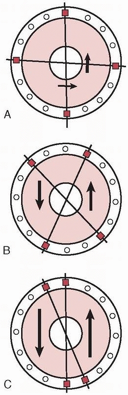
FIGURE 8-29 A.
Wire crossing angle of 90 degrees provides the most stable configuration with small mediolateral translations and a rigid frame. B. A wire convergence angle of 45 to 60 degrees allows acceptable amounts of translations to occur with satisfactory frame stability. C. As the convergence angle decreases, the translation increases dramatically to the point where the bone slides along a single axis. Parallel wires produce a grossly unstable frame configuration. |
 |
|
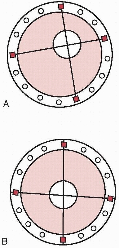
FIGURE 8-30 A. Eccentric bone location in the ring, simulating a tibial mounting. B. Center/center location of bone in the ring mounting simulating a femoral or humeral mounting.
|
the primary reason for loss of wire tension and thus frame instability.
Studies demonstrate that when clamping a wire to the frame, the wire
tension is reduced by approximately 7%.246 This may be due to wire deformation by the bolts and as such can reduce wire tension during fixator assembly.245
Slippage can be avoided by adequate torque on the fixation bolt (i.e.,
greater than 20 Newton meters [Nm]). Material yield accompanied by some
wire slippage through the clamps is responsible for the decreased
tension at the pin-clamp interface. Although, the initial wire tension
has an appreciable effect on the wire stiffness, it does not affect the
elastic load range of the clamp wire system. To prevent yield of the
clamp wire system in clinical practice, the fixator should be assembled
with sufficient wires to ensure that the load transmitted to each wire
by the patient does not exceed 15 N.250
Adding additional wires will increase frame stiffness directly
proportional to the number of wires in the system. Stiffness of an
Ilizarov frame is more dependent on bone preload than on wire number,
wire type, or frame design. Preload stiffness can be increased simply
by compressing the rings together and achieving bone-on-bone contact.1,15,16,37,40,41,83
take advantage of tensioned wires’ ability to stabilize complex
periarticular fractures. Early designs married a periarticular ring
using few tensioned wires to a monolateral bar connected to the shaft
using two or three half-pins. Unfortunately, these simple frames were
shown to be mechanically inferior in their abilities to alleviate
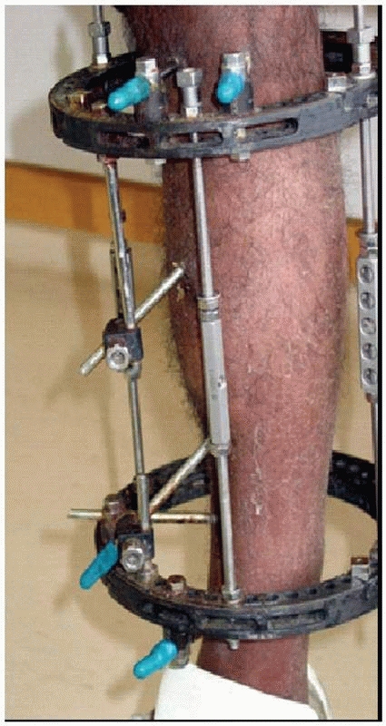
cantilever loading with resultant malunion/nonunion128,187,188,194,238 (see Fig. 8-10B).
Mechanical instability was especially pronounced when the frames were
applied with two prominent errors in technique. (a) Insertion of only
two transfixion wires in periarticular locations. Because of anatomic
constraints, the wires cannot be placed at 90 degrees to each other in
most periarticular locations. As noted previously, if the two wires are
not at 90 degrees, then the bone can translate easily along the two
wires. (b) Half-pins placed too far from the site of pathology put
significant strain on the connecting clamps to maintain frame stability
(Fig. 8-31).
half-pins and wires in the same frame mounting as well as using a
combination of rings and monolateral connecting bars. Stable hybrid
frames should include a ring incorporating multiple levels of fixation
in the periarticular fragment. This is accomplished with a minimum of
three or more tensioned wires and, if possible, an additional level of
periarticular fixation using adjunctive half-pins augments the
stability.5,6,15,34,128
periarticular ring places significant stresses on the single connecting
clamp and accentuating the harmful off-axis forces generated with
weight bearing. Multiple connecting bars or a full circular frame is
preferred with a minimum of four half-pins attached to the shaft
component.5,6,37,187,188,194,249
 |
|
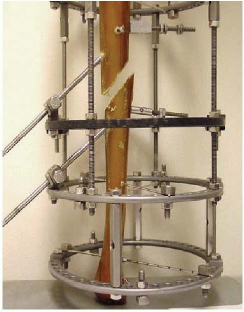
FIGURE 8-31
“Hybrid” frame demonstrating mechanical instability with only two periarticular tensioned wires on the distal ring and two small monolateral bars connecting only two diaphyseal half-pins located at an extreme distance from the fracture. This unstable fracture fixation went onto nonunion. |
physiologic stages depending on external forces imparted onto the
fracture site. There are four distinct types of fracture healing that
have been identified. External fixation facilitates external bridging
callus.
mechanical and other humoral factors and is highly dependent on the
integrity of the surrounding soft tissue envelope. The critical cells
necessary for healing are derived from the surrounding soft tissues and
from the revascularization response that occurs during the inflammatory
phase of fracture healing.1,33,112
large gaps and is very tolerant of movement. It results in the
development of a large callus with formation of cartilage due to the
greater inflammatory response caused by increased micromovement of the
fragments.126,136
Migrating mesenchymal cells from the surrounding area reach the
fracture ends where they differentiate into various cell types,
primarily cartilage. The cartilage is formed in the well-vascularized
granulation tissue due to its ability to repel vessels. These early
cartilaginous elements undergo remodeling through endochondral bone
formation. It is well known that this type of indirect bone healing
occurs under less-rigid interfragmentary stabilization.125,126,127
The rate of this type of healing and the extent of callus in this type
of repair can be modulated by mechanical conditions at the fracture
site.143 It has been shown that
applying cyclic interfragmentary micromotion for short periods of time
influences the repair process and leads to a larger area of callus
formation compared with those fractures that are rigidly fixed.*
Alternatively, efforts to reduce micromotion by increasing frame
stiffness can cause a significant reduction in the rate of healing.21,43,248,251
However, as the amount of fibrocartilage increases, the ability to
remodel and form bone is simultaneously decreased. There appears to be
some threshold at which the degree of micromotion becomes inhibitory to
this overall remodeling process and thus hypertrophic nonunion can
result. It should be noted, however, that fractures requiring external
fixation in general are usually more complex, which may result in a
higher rate of nonunion. Healing problems encountered in these severe
injuries may reflect the severity of the local soft tissue and
periosteal injury and should not be attributed solely to the inherent
features of the external fixation device.
fracture has been achieved. At this stage, the visible fracture lines
in the callus decrease and subsequently disappear. The bone transmits
mechanical forces to the encapsulating callus as the tissue
differentiates from granulation tissue to collagen and hyaline
cartilage, and then to woven intramedullary bone through the process of
endochondral bone formation.1,112,233
neutralize all forces including axial motion and allows the passage of
forces
across
the fracture site to occur. As the elasticity of the callus decreases,
bone stiffness and strength increase and larger loads can be supported.
Thus, the advantages of axial dynamization are that it helps to restore
cortical contact and produces a stable fracture pattern with inherent
mechanical support. Aro and colleagues11,13
described a uniform distribution of callus following dynamization and
noted this as “secondary contact healing.” By increasing cortical
contact, dynamization attempts to decrease the translational shear
forces.10,11,13
These forces are accepted by most to be the leading factor in producing
a predominance of fibrous tissue at the fracture site with resultant
delayed or nonunion.19,22,37,45
fixators. Active dynamization occurs with weight bearing or with
loading when there is progressive closure of the fracture gap. This
usually occurs by making adjustments in the pin bar clamps with simple
monolateral fixators or releasing the body on a monotube-type fixator.
Dynamization also decreases the pin-bone stresses and prolongs the
lifetime of the frame.1,119,125,152
load-carrying capacity of the healing bone and failure of the pin-bone
interface. In unstable fractures, very high stresses can occur at the
pin-bone interface, which may create localized yielding failure. In
half-pin frames, these high stresses are generated primarily at the
entry cortex and stress-related pin-bone failures of half-pins occur
mainly in this location.185
ends at the fracture site is a very important parameter in the healing
of the fracture. However, the threshold at which this motion becomes
deleterious is as yet unknown. Micromotion is the fundamental
mechanical force seen by the fracture construct, which is imparted to
the periosteal callus, and distinctions need to be made in terms of
quality, extent, and time of micromotion application.53,112
to perform limited internal fixation in combination with an external
fixator. While this type of methodology is very useful in metaphyseal
bone and has been demonstrated to work well in periarticular fractures,
its use in diaphyseal regions must be questioned.
direct bone healing through the use of constant compression. Primary
cortical healing occurs only when mechanical immobilization is absolute
and bony apposition is perfect. It is very intolerant of movement and
is not dependent on external soft tissues. This type of healing is very
slow and has no ability to cross gaps, as opposed to external bridging
callus.102,125
remodeling. Primary cortical healing is characterized by sequential
cutting cones of osteoclast across the fracture line with subsequent
reestablishment of new osteons. The vasculature develops from a budding
process sprouting from the intramedullary blood vessels, which are very
fragile and intolerant of motion. The external fixator, on the other
hand, does not entirely eliminate extraneous forces but seeks to limit
the degree of micromotion but still allow movement to occur along a
number of vectors.49,102,106,112,119,125,232
Therefore, because the bone is rigidly fixed with lag screws, very poor
bridging callus develops. Because external fixators do not produce
absolute rigidity, insufficient cortical healing occurs, demonstrating
the worst of both biological entities.178
This technique has been abandoned for use in diaphyseal regions,
because of the increased incidence of pseudoarthrosis. A combination of
internal and external fixation for diaphyseal fractures may at first
appear to be desirable but is in fact often disastrous and should be
avoided.215
new bone that occurs between bony surfaces that are gradually pulled
apart. Ilizarov described this as, “the tension stress effect.”1,112,113,114
Osteogenesis in the distraction gap of a distracted bone takes place by
the formation of a physis-like structure. New bone forms in parallel
columns extending in both directions from a central growth region known
as the interzone (Fig. 8-32). Recruitment of the tissue-forming cells for the interzone originates in the periosteum.1,16,17,112
Under the influence of tension stress, fibroblast-like cells found in
the middle of the growth zone have an elongated shape and are
orientated along the tension stress vector during distraction.
Surrounding the fibroblast-like cells are collagen fibers aligning
parallel to the direction of the tension vector. The fibroblastic cells
transform into osteoblasts, which deposit osteoid tissue upon these
collagen fibers. They further differentiate to become osteocytes within
the bone matrix laid down upon the longitudinal collagen bundles. These
cells will become incorporated into their own HA matrix as the collagen
bundles are consolidated into bone. This tissue gradually blends into
the newly formed bone trabeculae in the regions farthest away from the
central interzone. Thus, newly formed bone grows both proximally and
distally away from the middle of the distraction zone during
elongation. These columns of bone will eventually cross the fibrous
interzone to bridge the osteogenic surfaces following distraction1,112,113,114 (Fig. 8-32B).
zone proceeds via direct intermembranous ossification omitting the
cartilaginous phase characteristic of endochondral ossification.
Distraction osteogenesis also provides a significant neovascularization
effect. The fibroblast precursors are concentrated around sinusoidal
capillaries. The growth of these newly formed capillaries under the
influence of tension stress proceeds very rapidly and in some instances
overgrows development of bony distraction, resulting in enfolding of
this tremendous capillary response. This dense network of newly formed
blood cells has a longitudinal orientation connecting to the
surrounding soft tissue vessels by numerous arteries that perforate the
regenerate bone. Thus, the regenerate distraction gap is very vascular,
with large vascular channels that surround each longitudinal column of
distracted collagen. Neovascularization extends from each bone end
surface toward the central fibrous interzone. This intense formation of
new blood vessels under the influence of tension stress occurs not only
in bone but also in the soft tissues. These vessels contain a thin
lining of endothelial cells very similar to the neovascular response
that occurs in a centripetal fashion during routine fracture healing (Fig. 8-32B).
achieving viable tissue following distraction histogenesis. Histologic
and biochemical studies have determined that a distraction rate of
0.5
mm per day or less leads to premature consolidation of the lengthening
bone, while a distraction rate of 2 mm or greater often results in
undesirable changes within the distracted tissues. Faster rates of
distraction will disrupt the small vascular channels and areas of cysts
can occur inhibiting mineralization.1,16,17,112,113,114
 |
|
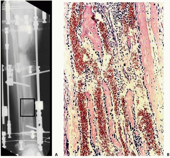
FIGURE 8-32 A. Interzone (box) is the central growth region involved in the genesis of new bone formation during distraction. B.
Collagen fibrils line up along the vector of distraction. Osteoblasts line the collagen bundles forming new bone. There are large vascular channels surrounding each collagen bundle. |
preservation of the periosteal tissues, bone marrow, and surrounding
soft tissue blood supply at the time of osteotomy is mandatory.1,112,253
The new bone or soft tissues are formed parallel to the tension vector
even when the vector is perpendicular to the limb’s overall mechanical
axis.
distraction (rate of distraction) per day. The actual number of
distractions (rhythm of distraction) should be at least four each day,
achieving the total daily distraction in four divided doses. His work
has also demonstrated that constant distraction over a 24-hour period
produces a significant increase in the regenerate quality compared with
other variables.1,112,113,114
resorption always occurs. The greater the interfragmentary motion at
the site of the fracture, the greater is the resorption of the fragment
and the slower is the consolidation. The healing process depends on
arterial revascularization, and if the fracture fragments are
excessively mobile, the local blood supply is traumatized by the moving
bone ends.49,178,232
Instability that introduces translational shear across the distraction
gap will result in an atrophic fibrous nonunion with mixed cartilage
and incomplete vascular channels, interspersed within the longitudinal
collagen columns. In these areas of mechanical instability,
intramembranous ossification is irregular with islands of endochondral
ossification seen, and if local vascularity is insufficient,
mineralization will be inhibited, leaving necrotic fibrous areas or
vascular cysts.
This stabilizes the small blood vessels and allows for neutralization
of the forces that are destructive to the neovascular region.16,17 This allows endochondral bone remodeling to proceed.
the bone does not suppress the reparative process and does not cause
damage to or resorption of the bone tissues. Under conditions of both
compression and distraction in the presence of stable fixation, bone is
actively formed by cellular elements of the endosteum, bone marrow, and
periosteum. The osteogenic activity of connective tissue is stimulated
by tension stress when the tissue is stabilized. Soon after the end of
distraction, the connective tissue is replaced by bone. Therefore,
compression (i.e., active compression) or dynamization can facilitate
healing of delayed or nonunions under this mechanical environment.
Increase in axial loading is accompanied by enhanced blood supply that
activates osteogenesis.1,112,113,114,232
Many authors have demonstrated the positive benefit that axial loading
combined with muscular activity has on new bone formation.125,126,127,135
application of prolonged tension with metaplasia and the
differentiation into the corresponding tissue type. Bone responds best
followed by muscle, ligament, and tendons in that order. Neurovascular
structures will respond with gradual new vessels and some degree of
nerve and vessel lengthening. However, they respond very slowly and are
intolerant of acute distraction forces.1,112,113,114
indirectly via traction on living tissue, as well as with tension
stress simulated by nonviable implants (i.e., the implantation of soft
tissue expandable prosthetics).102
 |
|
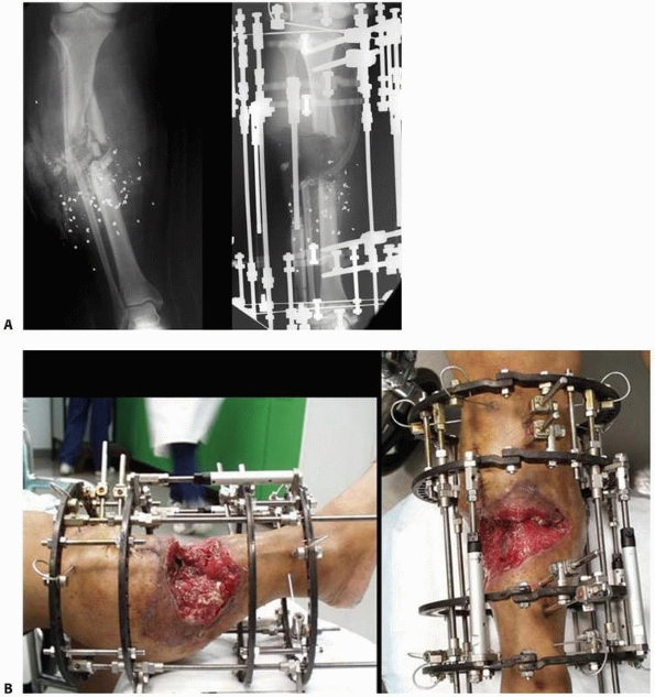
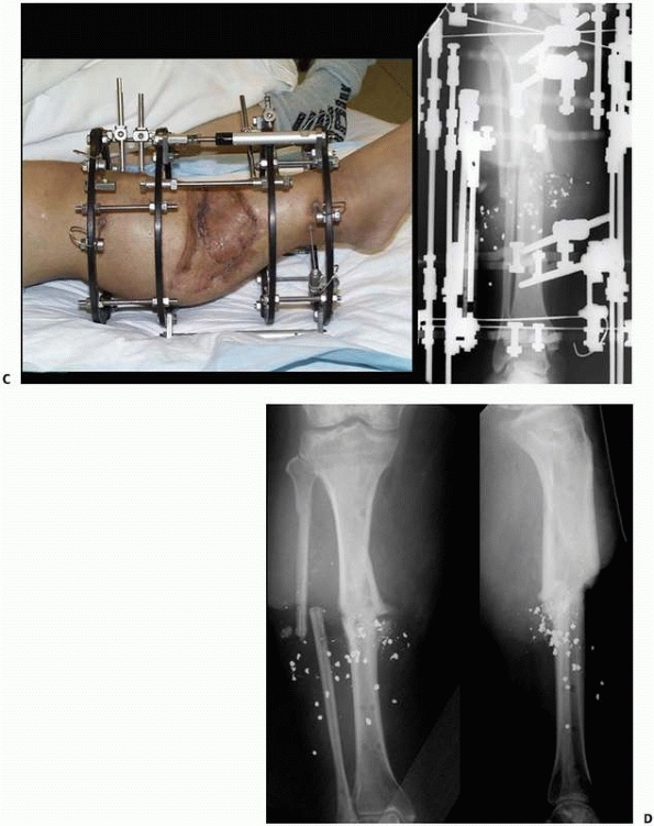
FIGURE 8-33 A. Severe bone and soft tissue loss stabilized with a ring fixator. B. Gradual distraction (compression) across defect gradually closes down the defect via soft tissue transport. (continues)
|
increasing the number of myofibrils in preexisting muscle. Muscle also
responds by the formation of new muscle tissue through the increased
numbers of muscle satellite cells, the appearance of myoblasts, and
their fusion into myotubes as well as differentiation of the
sarcoplasmic components of the existing muscle fibers into new muscle
tissue. Within the newly formed muscle fibers, active formation of
myofibrils and sarcomeres also occurs.1,112,113,114
stimulated by tension stress. Smooth muscle activity and proliferation
are accompanied by an increase in the extent and number of
intercellular contacts between myocytes and by the formation of new
elastic structures. These morphologic changes in the ultrastructure of
arterial smooth wall muscle cells resemble the changes seen in the
walls of arteries elongated during active prenatal and early postnatal
growth.1,112,113,114
of fascia, tendons, and dermis. The number of fibroblasts is increased
during distraction and an increase in the density of intracellular
junctions is multiplied, which is characteristic of fibroblasts in the
developing connective tissue of embryos, fetuses, and newborn animals.
The adventitial blood vessels in the epineurium and perineurium of
major nerve trunks also undergo similar changes.1,112,113,114
fixator, or a stable monotube device, initiates the histogenesis of
bone, muscle, nerves, and skin.1,16,17,112,113,114
This facilitates the treatment of complex orthopaedic diseases,
including pathologic conditions such as osteomyelitis and fibrous
dysplasia. Other conditions that have been historically refractory to
standard treatments, such as congenital pseudoarthrosis and severe
hemimelias, can also be addressed.*
defects with normal healthy bone structure, which is well vascularized
and is relatively impervious to stress fractures. The ability to
correct significant angular, translational, and axial deformities
simultaneously through relative percutaneous techniques, as well as
perform these corrections in an ambulatory outpatient setting, adds to
the attractiveness of this methodology** (Fig. 8-33).
 |
|
FIGURE 8-33 (continued) C. Skin grafting was performed over reconstructed soft tissues, once docking of the bone ends had been completed. D. Healed tibia later underwent limb lengthening.
|
primarily for trauma applications. This included the treatment of open
fractures and closed fractures with high-grade soft tissue injury or
compartment syndrome. For patients with multiple long bone fractures,
external fixation has been used as a method for temporary, if not
definitive, stabilization of these long bone injuries.
indications have been expanded to include the definitive treatment of
complex periarticular injuries, which include high-energy tibial
plateau and distal tibial pilon fractures. With the introduction of
minimally invasive techniques, combined with locking plate
technologies, the indications for use of circular fixation for the
definitive fixation of periarticular fractures has narrowed. Circular
fixator use in periarticular injuries is largely restricted to the most
severe fractures patterns with extensive comminution, bone loss, or
critical soft tissue injury.
external fixation, their use in reconstructive orthopaedics has gained
wider acceptance and is currently used for limb lengthening, osteotomy,
fusion, and deformity correction, as well as bone transport for the
reconstruction of bone defects (see Fig. 8-14B).
an initial ligamentotaxis reduction substantially decreases the amount
of injury-related swelling and edema by reducing large fracture gaps.
It is important to achieve an early ligamentotaxis reduction, as a
delay for more than a few days will result in an inability to disimpact
displaced metaphyseal fragments. When definitive stabilization is
attempted, reduction will be more difficult by indirect means and may
require larger or more extensile types of incisions.181,209,239,241,243
described. Most commonly used are the knee- or ankle-bridging
constructs. This may be a simple quadrilateral frame, constructed by
applying medial and lateral radiolucent external bars to proximal and
distal threaded transfixion pins placed across the respective joint.
Manual distraction is carried out and a ligamentotaxis reduction is
achieved. A simple anterior monolateral frame can be used to maintain
similar reduction across the knee joint for temporizing the management
knee dislocations, complex distal femoral fractures, and tibial plateau
fractures181,209,239,241,243,244 (Fig. 8-34).
triangular-type construct about the distal tibial and ankle region in
an effort to achieve relative stability. With temporary fixation in
place, the patient is then able to have other procedures or tests
performed while effective distraction is maintained and the soft
tissues are put to rest (Fig. 8-35).
patient is valuable when rapid stabilization is necessary for a patient
in extremis, so-called damage control orthopaedics (DCO). Simple
monolateral or monotube fixators can be placed very rapidly across long
bone injuries, providing adequate stabilization to facilitate the
management and resuscitation of the polytraumatized patient.98,219
Excessive traction across a joint should be avoided when applying these
temporary joint-spanning frames. By overdistracting these extremities,
the muscular compartments can become stretched, effectively compressing
the compartments, and lead to late compartment syndrome.72
definitive stabilization is usually based on the adequacy of soft
tissues. A latency period of at least 10 to 14 days is required to
allow the soft tissues to recover to the extent where contemporary
internal fixation techniques can be undertaken safely. Many series have
demonstrated excellent results achieved with a staged approach
consisting of early fracture stabilization using spanning external
fixation. This is followed by careful preoperative planning based on
traction computed tomography scans and the judicious clinical
evaluation of the soft tissue injury prior to definitive internal
fixation.4,141,177,181,209,239
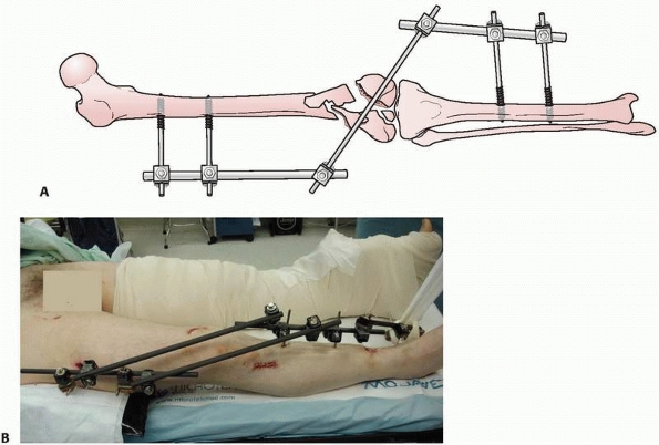 |
|
FIGURE 8-34 A. Monolateral components used to temporarily stabilize complex injuries around the knee. B. Temporary knee-spanning frame placed in a polytrauma patient. (continues)
|
intramedullary nail is determined by the condition of the soft tissues
and the overall stability of the patient. With the temporary
stabilization of long bone fractures, definitive conversion to
intramedullary nailing has demonstrated variable success especially in
the tibia.61 Most authors would
suggest early (within the first 2 to 3 weeks of frame application)
conversion to intramedullary nailing to avoid colonization of the
medullary canal by the external fixator pins. Increased infection rates
have been documented when conversion is done after 2 weeks of external
fixation. It has been shown that the longer the external fixator
remains in place, the greater is the risk of complications occurring
following conversion to intramedullary devices, especially if the pins
are removed and the nail exchanged at the same operative setting115,156 (Fig. 8-36).
nailing has demonstrated good rates of success if the exchange is done
when the patient’s overall physical condition has improved. Acute
conversion to an intramedullary device for the femur in a single
procedure is preferred in patients without evidence of pin track
infection. However, studies have shown that infection rates after DCO
for femoral fractures are comparable to those after primary
intramedullary nailing. There appears to be no contraindication to the
implementation of a damage control approach for severely injured
patients with femoral shaft fractures where appropriate. Pin-site
contamination was more common where the fixator was in place for longer
than 2 weeks.
For
patients treated by using a DCO approach, conversion to definitive
fixation should be performed in a timely fashion. Delayed conversion
requires a period of traction before nailing to avoid significant
shortening of the fracture. Certainly, prolonged traction while
awaiting pin site contamination to resolve is contraindicated in the
multiply injured patient.26,103
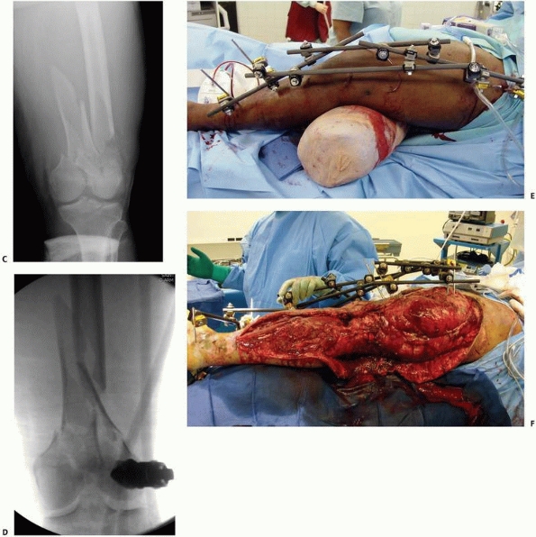 |
|
FIGURE 8-34 (continued) C-E. Open distal femoral and proximal tibial fracture stabilized with a knee-spanning frame. F.
Patient with a severe crush injury to lower extremity with multiple fractures and compartment syndrome. Entire limb was spanned to include the patient’s knee and ankle. |
achieved by the rapid application of simple external fixation for use
in the immediate resuscitative period. The application of an external
frame affords significant reduction in the volume of the true pelvis,
as well as stabilizing the movement of large bony cancellous surfaces
along the posterior aspect of the pelvic ring. The ability to provide
stabilization and decrease the pelvic volume allows the surgeon to
control hemorrhage and has helped to contribute to the low mortality
seen with these injuries.56,124
excellent adequate fixation, and traditional constructs include single
and multiple pin placements in several locations in each iliac crest.
However, anterior frame application, specifically the anterior superior
iliac crest pins that course between the inner and outer iliac tables,
may be problematic. These frames may be difficult to apply in a large
obese patient.97 As well, these pins may loosen very rapidly due to the variable pin purchase in cancellous bone (Fig. 8-37).
region. Pins in this location are more stable biomechanically because
of the improved purchase in the hard cortical bone of the posterior
column (Fig. 8-38).
This pin placement allows for pelvic reduction in the transverse plane
of deformity and may allow improved reduction of the posterior
elements. In addition the location of the pins and frame can facilitate
concurrent or subsequent laparotomy procedures.85,138
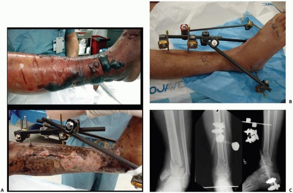 |
|
FIGURE 8-35 A.
Severe ankle fracture dislocation with compartment syndrome and significant soft tissue compromise was spanned with a triangular ankle-spanning external fixator (top). Open pilon fracture stabilized with triangular ankle spanning configuration (bottom). The reduction achieved with the simple frame facilitates the definitive reconstructive procedures once soft tissue recovery has occurred and the fasciotomy incisions have healed. B. Pilon fracture stabilized with an ankle-spanning frame. The forefoot was maintained in neutral with the addition of a metatarsal pin. C. A ligamentotaxis reduction maintained alignment and allowed definitive reconstruction once the soft tissues had recovered. |
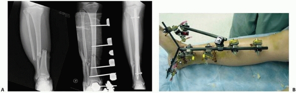 |
|
FIGURE 8-36 A. Open tibial shaft fracture with complex foot injury is temporarily stabilized with a spanning monolateral fixator. B.
An anatomic reduction was achieved and maintained with the frame. Once soft tissues recovered and the patient’s condition stabilized, the frame was converted to an intramedullary nail at 10 days postinjury. |
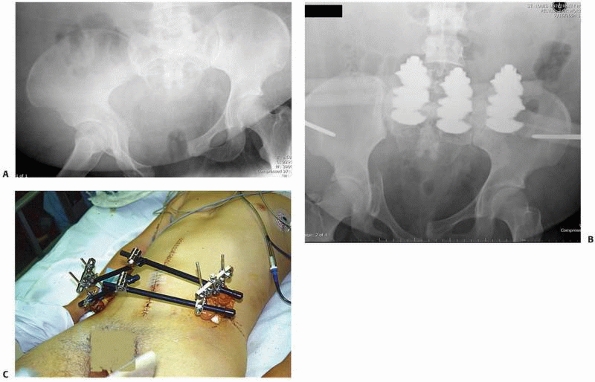 |
|
FIGURE 8-37 A.
Pelvic injury with anteroposterior disruption and hemodynamic instability. Note large pannus prohibiting supra-acetabular pin placement. B. This patient underwent simple anterior frame application to help in the resuscitation of the patient and provide temporary pelvic stabilization. C. Another patient with a different anterior iliac wing frame, which was modified with additional iliac crest pins and additional bars to increase stability. |
Rotationally unstable fracture such as AP compression and lateral
compression injuries are best suited to application of an anterior
pelvic frame.56 At times, the
application of an anterior frame may be complicated, cumbersome, and
time consuming and may be contraindicated as an emergency application.
For this reason, a modification of pelvic external fixation, the
so-called C-clamp, is used to provide posterior stability temporarily
in the patient with massive pelvic ring injuries and massive hemorrhage.
location and complexity of the fracture, as well as the type of wound
present when dealing with open injuries. The less stable the fracture
pattern, the more complex a frame needs to be applied to control motion
at the bone ends. If possible, weight bearing should be a
consideration. If periarticular extension or involvement is present,
the ability to bridge the joint with the frame provides satisfactory
stability for both hard and soft tissues. It is important that the
frame be constructed and applied to allow for multiple débridements and
subsequent soft tissue reconstruction. This demands that the pins are
placed away from the zone of injury to avoid potential pin site
contamination with the operative field.
extra-articular injuries in that they allow for immediate weight
bearing and can gradually correct deformity and malalignment, as well
as achieve active compression or distraction at the fracture site.
for fracture management occurs in the distal radius and in the tibial
shaft. This is followed closely by temporary application of trauma
frames for complex femoral and humeral shaft injuries. Much less likely
is the use of monolateral frames for forearm injuries.
distal radiu, and may be either joint bridging or joint sparing.
Following the restoration of palmar tilt by closed fracture
manipulation, wrist position can be adjusted into neutral or extension
to help avoid finger stiffness and carpal tunnel syndrome without
compromising fracture reduction.2
For unstable fractures, it has been shown that augmentation of the
fixator construct with multiple dorsal and radial percutaneous pins
corrects the dorsal tilt and maintains the reduction in those fractures
that are difficult to maintain with distraction ligamentotaxis alone51,148,166 (Fig. 8-39).
has demonstrated mixed results. The concept behind this was to achieve
a ligamentotaxis reduction, as well as initiate early range of motion
by uncoupling the device.91
For distal radius fractures with metaphyseal displacement but with a
congruous joint, there exists a trend for better functional, clinical,
and radiographic outcomes when treated by immediate external fixation
and optional K-wire fixation. Although there is insufficient evidence
to confirm a better functional outcome, external fixation reduces
re-displacement and provides improved anatomic results, and most of the
surgically related complications are minor, probably related to
technique of pin insertion.100,129,142,217 External fixation devices function best when maintaining radial length alone.84
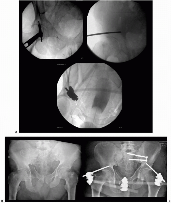 |
|
FIGURE 8-38 A.
Correct location of supra-acetabular pins localized with intraoperative fluoroscopy. Pins traverse the area just superior to the dome of the hip joint and gain purchase in the dense cortical bone of the posterior column. B,C. Use of supra-acetabular pins in conjunction with posterior ring fixation necessary to stabilize this complex pelvic injury with bladder rupture. |
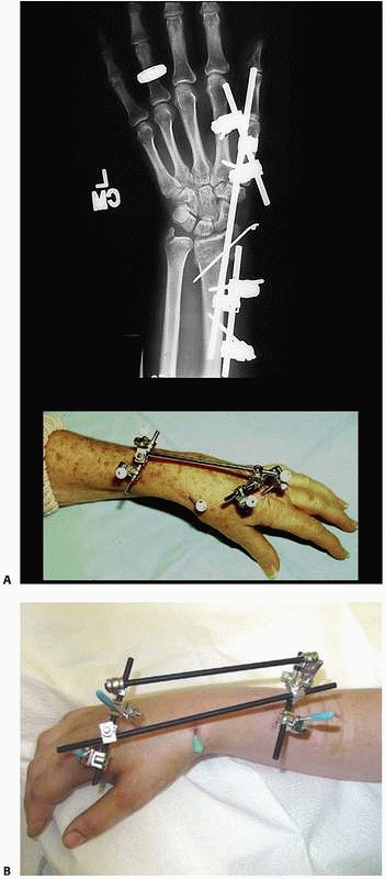 |
|
FIGURE 8-39 A.
Mini fixator used in combination with percutaneous pins to maintain reduction of a distal radius fracture. Solitary connecting bar placed between the metacarpal and radial pins. B. Alternative configuration using quadrilateral frame construct with percutaneous pins. |
length to be restored with the fixator; however, the anatomic reduction
of articular fragments and restoration of the normal volar tilt prove
to be more difficult when using a joint-spanning frame. A method of
nonbridging external fixation combined with percutaneous pinning
facilitates fracture reduction and allows for free wrist movements (Fig. 8-40).
This method has demonstrated no clinical differences when used for both
intra- and extra-articular distal radius fractures compared with wrist
bridging fixation.18,92,130,170
The ability to maintain the reduction and minimize the total load
transmitted from the wrist joint to the fracture site is fixator
dependent and will differ from manufacturer to manufacturer.84,252
femur fractures is primarily limited to pediatric indications or to
those fractures with significant soft tissue or neurovascular
compromise or to those severely injured patients who cannot tolerate
more extensive surgery (DCO). Commonly, femoral applications include
the use of a minimum of four pins placed along the anterolateral aspect
of the femoral shaft. These simple monolateral frames have been shown
to provide adequate stabilization for most complex femoral fracture
patterns28,57 (Fig. 8-41).
Fixator constructs with independent pins placed out of plane relative
to one another allow for safer pin insertion and demonstrate increased
stability over monotube or simple monolateral frames where pins are
placed in a straight line orientation.29,66
femoral shaft fractures is often the definitive treatment. Monolateral
or monotube fixators are commonly used with four- or six-pin
configurations. A pin tract infection with occasional pin loosening is
the most commonly reported complication and, although a common
occurrence, is not a major problem and can be treated with local wound
care and antibiotic therapy. The most common problem is significant
decrease in the range of motion of the knee, which can be difficult to
treat successfully and is the major drawback to using this routinely
when other methods are available.75,257
following frame removal, especially when used in a pediatric population
for definitive femoral shaft fracture treatment.42,189
regard to the structures that have been damaged and the best treatment
option. Knee dislocation in the polytrauma patient is also problematic
in the context of open knee dislocations or dislocation in association
with arterial disruption, or compartment syndrome.
arterial repair, compartmental release, or the treatment of other
injuries, spanning external fixation is a valuable option. Simple
knee-spanning monolateral or monotube fixators can be easily applied
with two pins above the knee located in the distal femur
and
two pins in the midtibia. The knee is reduced under fluoroscopy and the
fixator locked, maintaining the reduction to facilitate other
procedures and avoid the phenomenon of re-dislocation that can occur
when stabilizing these severe injuries with temporary splinting or
casting (Fig. 8-42).
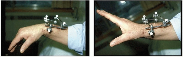 |
|
FIGURE 8-40
Fracture-spanning wrist fixator allows for range of motion with no loss in stability. This jointsparing configuration is indicated in certain select distal radius fractures. |
cruciate ligament or acute posterolateral reconstruction) of the
globally unstable knee, some investigators advocate the immediate
application of an articulated hinged knee fixator to protect these
extensive repairs. Articulated external fixation has been proposed as a
method to protect ligament reconstructions while allowing aggressive
and early postoperative rehabilitation after knee dislocation.116,256
stability afforded to knees by these monolateral or bilateral hinged
knee frames.214 Application of
articulated external fixators to specimens with intact ligaments
significantly reduced cruciate ligament forces for Lachman, anterior
drawer, and posterior drawer tests.
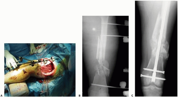 |
|
FIGURE 8-41 A-C.
Severe soft tissue injury prevents acute intramedullary nailing of the femoral shaft fracture. Stability required spanning across the knee to maintain reduction. Secondary conversion to intramedullary nailing occurred at 12 days postinjury with no secondary infection noted. |
stresses in the cruciate ligaments after multiligament reconstructions
and can decrease anteroposterior translation in the cruciatedeficient
knee.82
the management of acute humeral shaft fractures. Unlike the tibia, in
which fixator half-pins can be placed perpendicular to the subcutaneous
medial tibial surface, external fixation in the humerus often involves
transfixion of crucial musculotendinous units.
Complications
related to these frames may include pin tract sequelae and an
inhibition of shoulder and elbow motion. However, with contemporary
fixation devices, indications for use in the humerus continue to
expand. In addition to their initial use for shaft injuries, many
series now report the successful treatment of supracondylar and
proximal humerus fractures treated with monolateral, circular, and
hinge fixators.46,104,151
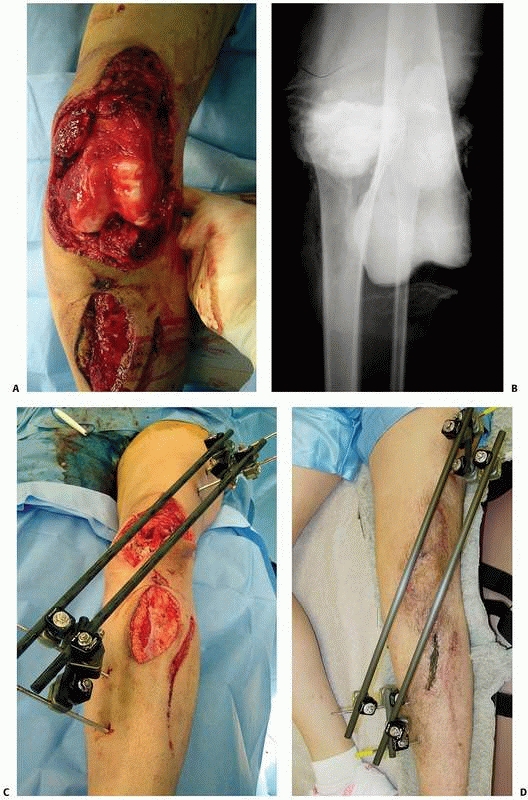 |
|
FIGURE 8-42 A,B. Severe open knee dislocation in conjunction with arterial disruption. C,D.
Emergent knee-spanning fixator was applied at the time of initial surgical management, which included arterial repair and multiple débridements. The wound was eventually closed, and the patient underwent delayed ligamentous reconstruction at 10 weeks postinjury. |
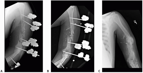 |
|
FIGURE 8-43 A.
Segmental humerus fracture in association with arterial injury. The fracture was emergently stabilized with spanning external fixator and arterial repair. B. At 6 weeks postinjury, demonstrates callus formation. C. Frame was removed at 10 weeks postinjury with translation and angulation but complete healing of this segmental injury. |
for the stabilization of severely contaminated open fractures or in
gunshot wounds that occur in association with vascular disruption (Fig. 8-43).
Rapid application of a simple four-pin external fixator provides
excellent stability such that the limb may be manipulated during
subsequent vascular arterial repair without concern for disruption of
the repair. External fixation together with radical debridement has
reduced the incidence of chronic infection and improved the prognosis
for the vascular repair (Fig. 8-44). Average
fixator time is dependent on associated extremity injures and has been
reported to be an average 16 weeks for these severe injuries. Secondary
surgical procedures for soft tissue and bony reconstruction are
facilitated and reported rates of pin tract infection are relatively
low.78,106,165,172
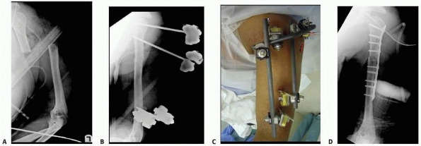 |
|
FIGURE 8-44 A. Multiply injured patient with open proximal humerus. B,C. Damage control measures included application of fracture-spanning external fixator. D.
When patient had recovered from initial injuries, definitive fixation was carried out at 9 days postinjury using plate fixation in conjunction with frame removal. |
complex shaft fractures, supracondlyar, intracondylar, and other
fracture-dislocations about the elbow can be temporized by the
application of a provisional elbow-spanning fixator. This reduces the
fracture at length with a generalized repositioning of the fragments
and can maintain the reduction of a grossly unstable elbow dislocation.
When the patient’s status improves, or the soft tissues recover, formal
treatment of the injuries can be safely undertaken (Fig. 8-45).
a hinge-type elbow fixator, or a static elbow-spanning fixator. The use
of a hinged external fixator for supplemental fixation of distal
humerus fractures may be effective in cases where internal fixation is
severely compromised by comminution or bone loss or in conjunction with
an unstable elbow joint.62
Other indications for the application of an elbow hinge fixator are
related to elbow instability as the primary pathology. This includes
recurrent dislocation or subluxation of the elbow after repair or
tenuous fixation of large coronoid fractures due to fragmentation or
osteopenia. The hinge fixator has also been used to augment the
reconstruction of bony, capsuloligamentous, and/ or musculotendinous
stabilizers following the open stabilization of the joint. A relative
indication for use of an elbow hinge includes providing stability
following fascial arthroplasty or débridement for infection, if the
débridement destabilizes the elbow.168,191,192,255
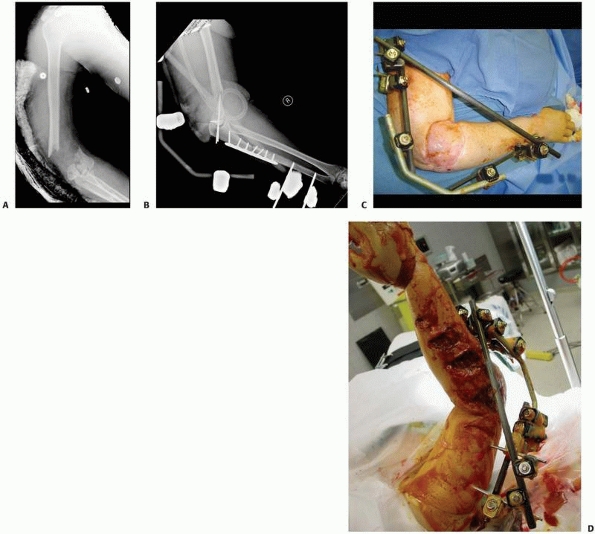 |
|
FIGURE 8-45 (A-C)
Severe open elbow injury with substantial bone and soft tissue loss. Stability was maintained with an elbow-spanning fixator which allowed free flap procedures as well as reconstruction of the elbow to proceed. (D) Multiple soft tissue and skeletal injuries of the entire upper extremity from a boat propeller injury. Stabilization accomplished emergently with a spanning fixator. |
restoration of stability and excellent motion after relocation of a
chronic elbow dislocation. Good results have also demonstrated its
usefulness as a tool following the reconstruction of acute and chronic
elbow instability or instability after fracture-dislocation (Fig. 8-46).
treatment options such as intramedullary nailing or compression plating
and bone grafting may not applicable or recommended, due to subclinical
infection, severe osteoporosis, poor soft tissues, or other confounding
variables. Many authors have advocated a one-stage debridement, with or
without autogenous bone grafting, and application of an Ilizarov
external fixator. The frame is then acutely compressed in the operating
room followed by slow gradual compression (0.25 to 0.50 mm per day) for
several weeks postoperatively (Fig. 8-47). Some
series report that the Ilizarov treatment of complex distal humeral and
midshaft nonunions that have failed internal fixation has been
successful
and has restored function, decreased pain, and improved quality of
life. The Ilizarov method may offer a salvage procedure with a
successful clinical outcome.32,190,225
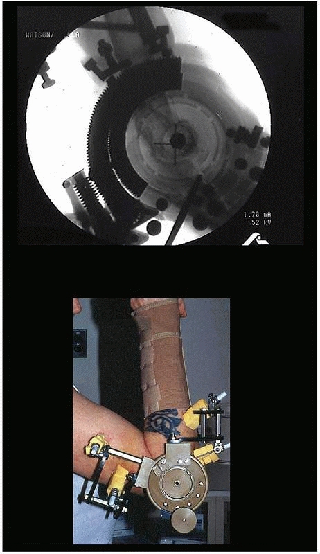 |
|
FIGURE 8-46
Elbow hinge placed to augment repair of a chronically dislocated elbow. Hinge assists in providing concentric reduction while the repair heals. Patient is able to continue to perform therapy without fear of re-dislocation. Hinge devices are very technique dependent, and placement of axis pin in the center of rotation of the distal humerus is crucial to maintain a concentric reduction of the elbow with range of motion (note fluoroscopy image documenting accurate center of rotation). |
candidates for closed intramedullary nailing; however, there are
occasions when external fixation is indicated. External fixation is
favored when there is significant contamination and severe soft tissue
injury or when the fracture configuration extends into the
metaphyseal/diaphyseal junction or the joint itself, making
intramedullary nailing problematic.
reduction, which also helps to limit the amount of operative time and
blood loss. It is useful in patients with multiple injuries or in the
patients where prolonged anesthesia is contraindicated. A simple single
or double bar unilateral system allows for independent pin placement,
while the larger Monotube frames facilitate rapid application with
fixed pin couples.26,47,71,78,80
that allow independent adjustments at each pin-bar interface, allowing
wide variability in pin placement, which helps to avoid areas of soft
tissue compromise. Because of this feature, simple four-pin placement
may be random on either side of the fracture. In general, the most
proximal and most distal pins are first inserted as far away from the
fracture line as possible and the connecting rod is attached. The rod
is positioned close to the bone to increase the strength of the system.
The intermediate pins can then be inserted using the multiaxial pin
fixation clamps as templates with drill sleeves as guides. Upon
placement of these two additional pins, the reduction can then be
achieved with minimal difficulty (see Figs. 8-19 and 8-20).
a solitary bar and the distal two pins are connected to a solitary bar.
Both proximal and distal bars are then used as reduction tools to
manipulate the fracture into alignment. Once reduction has been
achieved, an additional bar to bar construct between the two fixed pin
couples is connected.
placement of these devices with the fixed pin couple acting as pin
templates. Two pins are placed through the fixator pin couple proximal
to the fracture and two pins are placed through the pin couple distal
to the fracture. Care must be taken to allow adequate length of the
Monotube frame prior to final reduction and tightening of the body (Fig. 8-48).
limits the amount of shearing, torsional and bending movements of the
fixation construct. Axial compression is achieved by releasing the
telescoping mechanism. Dynamic weight bearing is initiated at an early
stage once the fracture is deemed stable. In fractures that are highly
comminuted, weight bearing is delayed until visible callus is achieved
and sufficient stability has been maintained. The telescopic body
allows dynamic movement in an axial direction, which is a stimulus for
early periosteal healing.12,13,14
actively across fracture fragments, fracture gaps secondary to
comminution and minimal bone loss can be closed directly by this
maneuver. Fracture gaps secondary to malalignment can be corrected
sequentially as bone union takes place. This can be accomplished with
most circular and select monolateral fixators with three-dimensional
adjustability.13,15,174
heal on an average in 4 to 5 months. In an effort to accelerate this
rate, most proponents of external tibial fixation believe that early
dynamization or gradual frame disassembly should be performed in an
effort to effect load transfer to the fracture and promote secondary
callus formation. Research and clinical studies have been inconclusive
on the advantages of passive dynamization. However, dynamization does
seem to facilitate fracture healing if it is used within the first 6 to
8 weeks following the fracture. Kenwright and colleagues demonstrated
significant improvement in the time to union with active dynamization.125,126,127
2-cm discrepancy will be the result, then dynamization is not
indicated. Most external fixators have bone transport capabilities as
an option to regain limb length and skeletal continuity.234,237
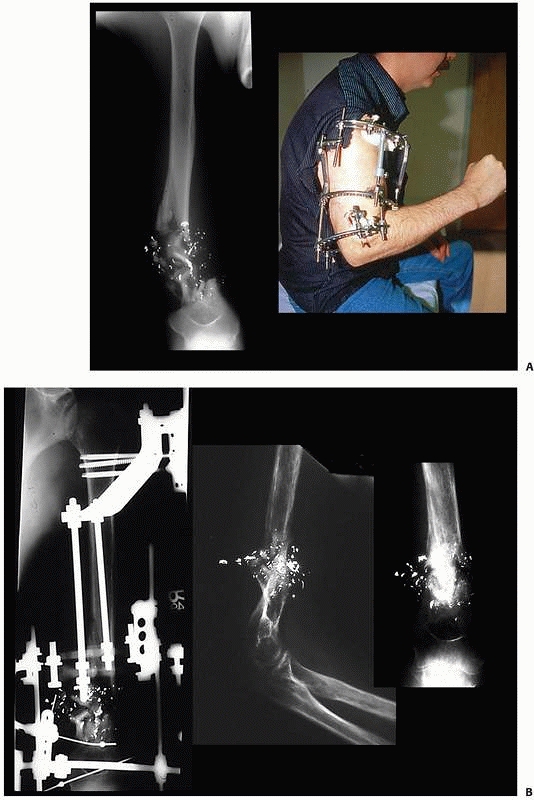 |
|
FIGURE 8-47 A.
Segmental bone loss with small distal supra condylar remnant precluding traditional plate fixation of this injury. Ring fixator applied with sequential compression across comminution to achieve bone contact. B. Continued compression allowed healing of the humeral shaft fracture with approximately 1.5 cm of shortening; however, no bone grafting was necessary. |
have concomitant foot injuries as well. These patients require multiple
reconstructive procedures and are often initially treated with external
fixation techniques such as a bridging frame. It is advantageous to
extend these frames down onto the hindfoot and forefoot to avoid the
common complication of equinous deformity. This can develop over time
specifically in those patients with a wide zone of injury, which can
cause the posterior compartment and other tissues to contract (see Fig. 8-35B).
half-pin techniques. This is easily accomplished when the fracture
occurs in the mid portion of the long bone, allowing adequate regions
of diaphyseal bone above and below the fracture to be stabilized by
half-pins, which achieve solid bicortical pin purchase.
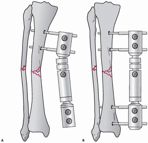 |
|
FIGURE 8-48 A.
Monotube fixator allows rapid reduction and stabilization for complex tibia fractures. Fixed pin connectors act as templates to place proximal pins. B. Distal pins are then applied again through the distal pin clamp. The Monotube allows for reduction in all three planes. Once reduction has been achieved, the Monotube is locked and reduction is maintained. |
tibial metaphyseal regions, transfixion techniques using small
tensioned wires are ideally suited to this region. They demonstrate
better mechanical stability and longevity compared with traditional
half-pin techniques.
periarticular wires, this approach may avoid the need to span the ankle
or the knee joint to maintain the reduction. The small tensioned wires
may be used in concert with limited open reduction if necessary. Olive
wires can be used to achieve and maintain “tension compression
fixation” across small metaphyseal fragments, similar to the effect
achieved with small lag screws. Therefore, the combination of smooth
and olive wires are be used to neutralize deforming forces across the
fracture lines and help to achieve and maintain compression across the
fracture lines1,112 (Fig. 8-49).
circular frame offers more adjustability and will not incur detrimental
mechanical forces such as cantilever bending. These detrimental forces
are commonly generated with traditional hybrid techniques if performed
incorrectly. The “hybrid” has evolved to include a traditional
monolateral diaphyseal bar attached to a solitary circular
periarticular ring. Full ring stabilization is preferable to
monolateral shaft stabilization because of the cantilever loading
accentuated with this construct. Specifically in the proximal tibia,
this type of frame configuration functions similar to a diving board,
producing tremendous loads at the metaphyseal diaphyseal junction with
associated development of nonunion or malunion.4,5,6,240,241,243,244
If monolateral adaptations are to be used, it is recommended that at
least three divergent connecting bars be attached to the periarticular
ring.6 The bars should be oriented
to achieve at least 270 degrees of separation to alleviate cantilever
loading. An additional disadvantage of this standard “hybrid” construct
is the inability to easily dynamize the fixator.187,188,238,249
fixator can be performed with the patient on either a fracture or
radiolucent table with calcaneal pin or distal tibial pin traction.
Following a ligamentotaxis reduction of the metaphyseal fragments,
olive wires or percutaneous small fragment screws can be used to
achieve interfragmentary compression of these metaphyseal components.
If necessary, limited incisions are used to elevate
the
depressed articular fragments as well as bone graft the subchondral
defects. It has been shown that at least three periarticular wires are
necessary to stabilize these injuries. Most authors using small wire
techniques recommend that as many wires as can be inserted safely
should be used for maximal stability.6,76,229,239,241,244,254
Biomechanical data support the use of tensioned wire fixation
stabilizing complex fractures of the proximal tibia. The stability
achieved with a four-wire fixation construct is comparable to that of
dual plating for bicondylar tibial plateau fractures.5,240,241
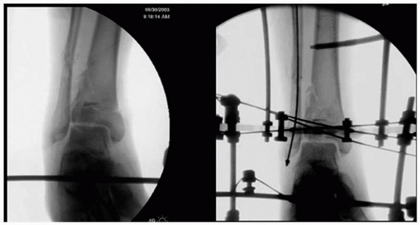 |
|
FIGURE 8-49 Ring construct using tensioned smooth and olive wires to stabilize small periarticular fracture fragments.
|
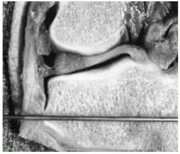 |
|
FIGURE 8-50
Anatomic specimen showing the capsular reflections around the knee joint. Care must be taken to avoid capsular penetration when placing periarticular wires around the knee. (Courtesy of Spence Reid, MD.) |
avoid the proximal tibial capsular reflection, as well as the distal
ankle joint to avoid tethering the capsule.87,229,231
This maintains the wires in an extra-articular location and avoids
secondary contamination of the joints, which can result in knee or
ankle sepsis (Fig. 8-50).
use of monotube ankle bridging and simple monolateral external fixator
designs.25,81
These are applied to achieve a distraction reduction across their
respective joints, followed by limited open reduction and internal
fixation. The advantage of using monotube constructs for either plateau
or pilon fractures is that articular fixation is achieved and
maintained without the use of small tensioned wires and the potential
for articular contamination is avoided224 (Fig. 8-51).
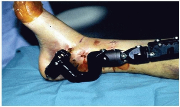 |
|
FIGURE 8-51 Monotube ankle-bridging fixator used to provide distraction in combination with limited internal fixation for pilon fractures.
|
shaft fractures continues to be a complex reconstructive problem. Many
procedures have been devised to reconstitute bone stock, obtain
fracture union, and provide a stable functional limb. Cancellous
grafting, whether placed directly into the defect or through a
posterolateral approach, has been the most common methodology; however,
often this technique requires numerous grafting procedures.47,48,223
Fibular bypass, tibial fibular synostosis, ipsilateral direct fibular
transfer, and free vascularized fibular transfer have been used to
reconstruct these large defects.48,71,77
Internal bone transport has been developed as a primary method of bony
reconstruction in acute tibial fractures with bone loss. This technique
is indicated for reconstruction of defects greater than 4 cm.*
Monotube monolateral fixator that has an intercalary sliding mechanism
to transport the bone segment. Likewise, ring fixators can also be
configured to perform successful intercalary bone transport.
of four or five rings. A stable proximal and distal ring block is
placed at the level of the knee and ankle joints. A transport ring is
placed in the midportion of the tibia. Orientation of the frame on the
limb is crucial to ensure that the proposed docking site is aligned and
will provide sufficient cortical contact for union to occur. Likewise,
appropriate alignment using a monotube construct is also critical to
ensure docking site alignment. The intercalary transport component is
attached to bone using either transfixion wires or half-pin techniques.
An antibiotic cement spacer is also placed across the defect. This
block provides additional stability to the frame-bone construct and
acts to maintain the transport space. The block remains in place until
the next debridement, free flap procedure, or delayed primary closure
of the wound (Fig. 8-52A).
block spacer is removed and a solitary string of antibiotic cement
beads is placed in the defect. The beads provide and maintain a
“potential space” or fibrous tunnel through which the transport segment
will travel. This space allows relative unencumbered movement of the
transport segment underneath the flap. If no flap is needed, the wound
is closed primarily and antibiotics beads are still used to maintain
the potential space and prevent invagination of the intact soft tissue
envelope into the transport pathway** (Fig. 8-52B-D).
the site of skeletal defect, then soft tissue transport in conjunction
with the bone transport is possible.48,57,113,114.
Tissue loss that exposes bone is not amenable to combined soft
tissue-bone transport without first addressing the exposed bone. This
is accomplished through rotational or free tissue transfer to cover the
bone. Alternatively, the bone should be resected back until healthy
soft tissue covers the bony segment.167,200,234,235
At this time, acute shortening or gradual shortening can be
accomplished and the soft tissue defect allowed to heal without
additional coverage procedures. Following soft tissue healing,
relengthening or deformity correction can then be carried out through
the use of the frame.
 |
|
FIGURE 8-52 A. A typical four-ring transport frame attaching the rings to the bone with either transfixion wires or half-pins. B.
Long alignment and plain films document the infected distal tibial defect. Previous intramedullary débridement was performed along with the application of antibiotic beads down the medullary canal, which had become ingrown and could not be removed. C. Transport frame applied with proximal tibial corticotomy. Resorbable calcium sulfate antibiotic beads maintain the potential space in the transport tract. As docking approaches, the beads were compressed and autografting to the docking site was carried out. (continues) |
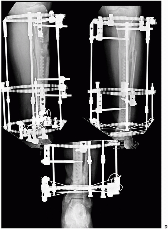 |
|
FIGURE 8-52 (continued) D.
The regenerate and docking sites appear healed. The regenerate is mature as is indicated by the reconstitution of the medial and lateral cortices, as well as reconstitution of the posterior cortex and nearly complete restoration of the anterior cortex. The frame was successfully removed without docking site nonunion or late deformity of the regenerate. |
flap coverage. If no flap is used, corticotomy and transport can be
undertaken immediately at the time of wound closure. This 3-week delay
allows for healing of the flap over the bony defect, as well as early
neovascularization of the zone of injury. The delay also allows the
free flap anastomosis site to become fully epithelialized, which is
then able to withstand the inevitable tension forces that it is
subjected to during the bone transport process.1,112
The location of the transport Schanz pins should be in the inferior
portion of the transport segment, so that it will “pull” the bone into
docking position” rather than “push” the transport segment. This is the
case if the pins were located more proximal in the transport segment.
This construct results in an unstable situation where the transport
segment will have a tendency to deviate during transport.1,94,95,112,242
or distal corticotomy is performed. Because of the wide zone of injury
that often occurs following open tibial fractures, it is better to
perform the corticotomy away from any region of soft tissue compromise.
A latency period of 7 to 10 days is allowed prior to the initiation of
transport. The initial rate of distraction begins slowly at 0.25 to 0.5
mm per day. A slower distraction rate is recommended initially because
of the wide variability in injury patterns and vascularity of the limb.
In more extensive fractures with a wide zone of injury, transport
should be undertaken very slowly and the regenerate bone visualized by
approximately 2 to 3 weeks postcorticotomy. The distraction rate can
then be adjusted depending on the quality of the regenerative bone.
Transport in the acute fracture proceeds at a much slower rate, 0.5 to
0.75 mm per day, as opposed to the standard rate of 1 mm a day typical
for standard limb lengthening.
This shortening aids in soft tissue coverage by decreasing tension and
gaps in the soft tissues. Shortening acutely can be accomplished safely
for defects up to 3 to 4 cm in the tibia and humerus. More shortening
can be tolerated acutely in a femoral defect up to 5 to 7 cm. In some
situations, it is advantageous to decrease the transport distance, and
thus time, in the frame. Shortening aids in soft tissue coverage by
decreasing tension and gaps in the open wound; this approach combined
with vacuum-assisted closure (VAC) may allow wounds to be closed by
delayed primary closure
or healed by secondary intention or simple skin grafting. With this technique, one may avoid extensive free flap coverage.48,57,113,114,167,200,234,235
recommended due to distortion of the neurovascular elements, which
results in the development of edema and inability of the
musculotendinous units to function properly242 (see Fig. 8-33).
Bone transport continues until the antibiotic beads have been
compressed to the width of one bead. At this time, the patient is
returned to surgery and the docking site is exposed. The beads are
removed and the bone ends are freshened to achieve punctate bleeding
surfaces. A high-speed burr can be used to fashion congruent surfaces
on the ends of the proposed docking segments. This ensures maximal
cortical contact and increases stability at the docking site.
Autogenous iliac crest bone graft is placed directly into the docking
site at this time, and distal transport is resumed within 24 hours of
the procedure.1,48,94,95,234,235,236
0.25 mm every 48 hours until the docking site is radiographically
healed. Numerous authors have found that grafting the atrophic docking
site aids in the speed of union with a subsequent decrease in the
overall time the patient must remain in the fixator.48,94,95,237
Bone transport is a reliable technique; however, it is very time
consuming and requires extreme patient compliance. The principles of
transport include a stable external fixation system above and below the
defect. The primary importance is the ability to develop a biologically
sound wound at the transport location.
more sophisticated, the ability to simultaneously correct a complex
deformity with a simplistic device has become more attractive. The
Taylor Spatial Frame was designed to allow simultaneous correction in
six axes (i.e., coronal angulation, translation, sagittal angulation
and translation, rotation and shortening). To achieve this with
conventional frames, a complex customized frame mounting would be
required. Additionally, the mounting of these traditional frames would
be fairly difficult due to the fact that the rings need to be placed
parallel to the respective reference joints, as well perpendicular to
the long axis of the limb. In cases of deformity or fracture, this can
be very problematic. The hexapod-type frames allow the rings to be
positioned in any orientation within their respective limb segment
(i.e., above the fracture site). It is not necessary that the rings be
parallel with respect to joints or perpendicular to the long axis of
the bones. This demanding technique has been vastly simplified using
this six-axis “hexapod” concept.205
a configuration consisting of 6 distractors and 12 ball joints, which
allows for 6 degrees of freedom of bone fragment displacement. By
adjusting the simple distractors, gradual three-dimensional corrections
or acute reductions are possible without the need for complicated frame
mechanisms.205
use depends on the use of computer software. Once the rings are
mounted, the deformity parameters are calculated with respect to
angulation, translation, in both the anteroposterior and lateral
planes. Additional information about rotational and axial malalignment
is also computed. These deformity parameters are then placed into the
software program along with the frame mounting parameters. The frame
mounting parameters include data points such as height of the distance
of the frame from the deformity or fracture site location. The overall
length of the six struts is also a variable, which is entered into the
software calculations. The program will then calculate the final strut
lengths necessary to achieve a corrected limb alignment. In addition,
daily strut adjustments can also be calculated to affect a very gradual
correction over a specific time period that the surgeon wishes to
achieve. The final alignment can be further adjusted using the same
software applying similar deformity and strut parameters to the program.196
placement of a relatively simple frame. The frame can be attached using
either transfixion wires or a minimum of three half-pins on either side
of the fracture. At this point, an approximate reduction can be
achieved grossly at the time of surgery and the final reduction can be
completed over a short period of time using the software program and
gradual adjustment of the six struts (Fig. 8-53).
The hexapod frames and Internet software offer the advantage of very
accurate and precise control of multiple deformities without
significant soft tissue dissection. A relatively straightforward and
simple external device is applied to effect these corrections.
to achieve gradual realignment of complex pediatric fractures and
deformities.3,74,79,213
One can comprehensively approach tibial nonunions with the Taylor
spatial frame (TSF). This is particularly useful in the setting of
stiff hypertrophic nonunion, infection, bone loss, leg length
descrepancy (LLD), and poor soft tissue envelope. Investigators have
determined that previously infected nonunions have a higher risk of
failure than non-infected cases; however, these results are consistent
with most studies treating infected nonunions by any modality.198,199
What is unique is the hexapod frames’ ability to resolve multiple
deformities and restore leg length equality with a relatively
simplistic frame application79,198,199,205,228 (Fig. 8-54).
secondary procedures are required. This may include soft tissue
coverage procedures or delayed bone grafting. Most external fixator
frames can easily be modified or placed out of the zone of injury. Most
surgeons find it problematic to drape the fixator out of the operative
field and maintain this unusually small area as sterile throughout an
entire procedure. The benefits of safely prepping an external frame
into the operative field include the ability to maintain reduction
during secondary conversion procedures, decreasing the time, material
cost, and frustration in trying to drape a fixator safely out of the
operative field. It has been shown that following standardized
protocol, precleansing the external fixator frame, followed by alcohol
wash, sequential povidone-iodine prep, paint, and spray with air drying
followed by draping the extremity and fixator directly into the
operative field, additional surgery can be safely performed without the
risk of an increased rate of postoperative wound infection.93,236
It is possible to perform free flaps and other soft tissue procedures
directly around the external fixator pins as long as the pins do not
communicate directly with the operative site.
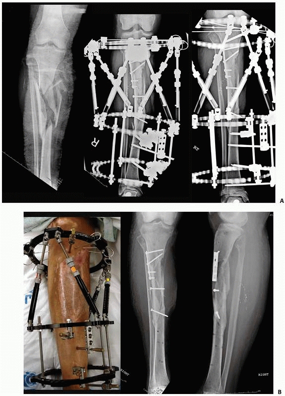 |
|
FIGURE 8-53 A.
Complex open proximal tibial fracture with bone and soft tissue loss. Acute management includes conversion of a spanning fixator to a Taylor Spatial Frame, with limited internal fixation at the time of free flap coverage. The valgus malalign-ment was gradually corrected over 10 days to restore the correct mechanical axis. B. The pin sites did not encroach into the flap region and required minimal pin care. The frame was removed at 14 weeks postinjury with alignment maintained. |
link in the stability of the external fixation system. External
fixation pins placed in cancellous metaphyseal bone frequently loosen
over time, resulting in fixation failure and increased risk for
infection. The fixation pin in cortical/diaphyseal regions can remain
intact and infection free for extended periods of time. Thus, each pin
in the fixation construct should be continually evaluated for these
potential problems to avoid an unstable fixator.
skin directly at the side of pin insertion. Following generous
incision, dissection is carried directly down to bone and the
periosteum is incised where anatomically feasible. A small
Penfield-type elevator is used to gently reflect the periosteum off of
the bone at the site of insertion. Extraneous soft tissue tethering and
necrosis are avoided by minimizing soft tissue at the site of
insertion. A trocar and drill sleeve are advanced directly to bone,
minimizing the amount of soft tissue entrapment that might be
encountered during predrilling. The drill sleeve should be centered in
the midportion of the medullary canal (Fig. 8-55).
One needs to ensure that the pin trajectory traverses the near cortex,
then the medullary canal, and finally exits the far cortex. In this
fashion, you avoid a transcortical pin, which is a stress riser and can
be a site of fracture once the frame has been removed. A sleeve should
also be used if a self-drilling pin is selected. Following predrilling,
a pin of appropriate depth is
advanced to achieve bicortical purchase and any offending soft tissue tethering should be released with a small scalpel.1,93
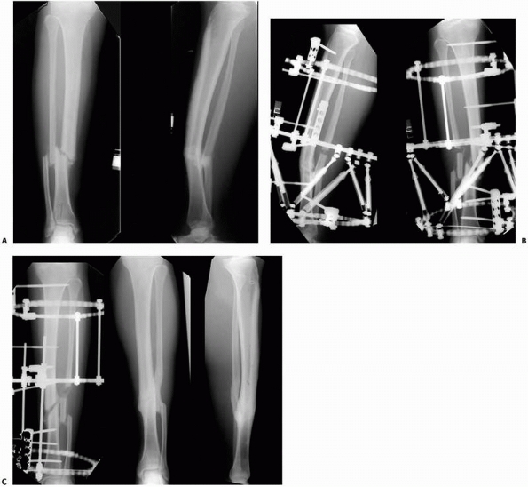 |
|
FIGURE 8-54 A. Complex tibial nonunion with malrotation, angulation, translation, and leg length discrepancy. B.
Taylor Spatial Frame applied to limb using primarily half-pin attachments. Patient’s selfadjustment of the six oblique struts will gradually correct all deformity parameters. C. Complete realignment and consolidation via gradual distraction osteogenesis; no grafting was required to achieve these results. |
identified. Pin site recommendations are based more often on clinical
preference rather than on strict research findings. The pin care
protocol should be based on the pathophysiologic processes involved in
the development of pin site infection.93
It should be noted that correct pin site insertion technique removes
most of the factors that cause pin site infection and subsequent pin
loosening.93,176
If appropriate insertion technique is used, the pin sites will
completely heal around each individual pin, much like a pierced earring
insertion site heals. Once healed, only showering, without any other
pin cleansing procedures, is necessary.247 The occasional removal of a serous crust around the pins using dilute hydrogen peroxide and saline may be necessary.1,25,88,93
Review of the Cochrane database with regard to the most effective pin
care regimen was undertaken. All randomized controlled trials comparing
the effect on infection and other complication rates of different
methods of cleansing or dressing orthopaedic percutaneous pin sites
were evaluated. Three trials compared a cleansing regimen with no
cleansing, two trials compared cleansing solutions, one trial compared
identical pin site care performed daily or weekly, and four trials
compared dressings. One of these trials reported that infection rates
were lower (9%) with a regimen that included cleansing with
half-strength hydrogen peroxide and application of Xeroform dressing
compared with other regimens.220
However, the authors agree with the conclusions of other investigators
that there is insufficient evidence for a particular strategy of pin
site care that minimizes infection rates.73,140
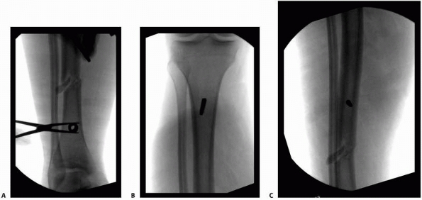 |
|
FIGURE 8-55 A.
The drill sleeve and trochar are centered on the bone to ensure that the pin is not eccentrically located and traverses both cortices and the medullary canal. The pin must engage the posterior cortex and be central in the bone to avoid postframe stress fracture through an errant transcortical pin tract. B,C. Central location of diaphyseal pins. |
these tend to inhibit the normal skin flora and alter the normal skin
bacteria, and thus can lead to superinfection or pin site colonization.149
It is important to remove the buildup of crusted material, which will
tend to stiffen the pin-skin interface and increase shear forces at the
pin-bone interface (Fig. 8-56A). This leads to the development of additional necrotic tissues and fluid buildup around the pin.51
Immediate postoperative compressive dressing should be applied to the
pin sites to stabilize the pin-skin interface and thus minimize
pin-skin motion, which can lead to additional necrotic debris. By
“training” the skin, the pin site remains stable.1,112
This allows the skin to heal around the pin undisturbed. Compressive
dressings can be removed within 10 days to 2 weeks’ time once the pin
sites are healed (Fig. 8-56B,C). If pin
drainage does develop, then providing pin care three times per day
should be undertaken. This may also involve rewrapping and compressing
the offending pin site in an effort to minimize the abnormal pin-skin
motion.112
significant difference in the rates of pin tract infection between
large Schanz half-pins and small transfixion wires. For acute fracture
fixation fixators, patients with hybrid external fixators demonstrated
a similar risk of pin tract infection as patients who had unilateral
fixators. The infection rate in the ring fixator (using small
transfixion wires) group was significantly lower than the hybrid
external and unilateral fixator groups (using primarily Schanz
half-pins).176
infection for limb-lengthening procedures demonstrated similar results.
The rate of half-pin site infection was significantly (P
< .05) higher in half-pin fixators (100%) compared with hybrid
fixators (78%) where a combination of thin wire and half-pins was used.
When half-pins were compared exclusively to thin wires, a significantly
(P < .05) higher incidence of half-pin site infection (78%) over fine-wire site infection (33%) was revealed.9
with correct technique (as described earlier) to avoid excessive soft
tissue impingement, incarceration, or development of necrotic tissue at
the site of half-pin insertion.
closed scrutiny of the radiographs to ensure that the fracture or
distraction site has completely healed prior to frame removal. Numerous
authors have described various techniques including computed tomography
scans, ultrasound, and bone densitometry to determine the adequacy of
fracture healing.1,16,17,112
In general, the patient should be fully weight bearing with a minimal
amount of pain noted at the fracture site. The frame should be fully
dynamized such that the load is being borne by the patient’s limb
rather than by the external fixator (Fig. 8-57).
For distraction osteogenesis, the patient’s radiographs are visualized
in the anteroposterior and lateral planes. It is necessary to see three
of four neocortices in the regenerate zone reconstituted to ensure that
the bone is mechanically stable and able to tolerate frame removal1,15,17,94,95 (Fig. 8-52D).
Late deformity following frame removal is very common and usually is
the result of incomplete healing of the distraction regenerate.1,112
In the tibia, this is because the subcutaneous border anteriorly has
the least amount of soft tissue coverage and thus blood supply.
However, mechanical stability requires only three of four reconstituted
cortices.
precautions should be adhered to in order to avoid refracture or the
development of nonunion. Four oblique views should be obtained to
determine the adequacy of fracture healing prior to frame removal.
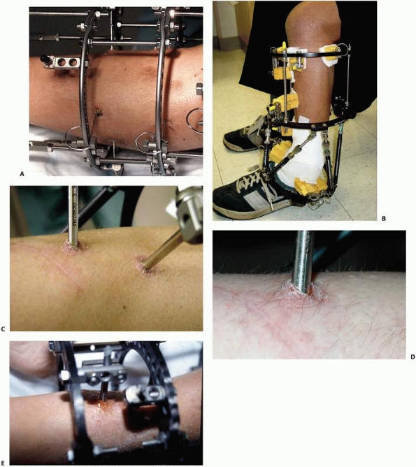 |
|
FIGURE 8-56 A.
While the pin sites are healing, the serous fluid that develops at the pin site develops crusting that should be removed with mild peroxide or mild soap and water. B. The pin-skin interface should be compressed and stabilized to minimize motion and subsequent development of any necrotic material. Gauze wraps around the pins or pin sponges can be used to provide the stabilization. C. Healed pin sites require no special care other than mild soap and water. No ointments or antiseptics are required for the maintenance of a healed/sealed pin site. D. Long-term pins develop painful hypertrophic keratosis surrounding the pin sites and should be excised at the time of pin removal. E. Grade 4 pin tract infection with seropurlulent drainage and redness requires vigorous pin care and antibiotics. (continues) |
is variable depending on the type of fixator pins used. A study
evaluated the ability to remove stainless steel pin fixators in the
office setting without anesthesia. Removal of these particular external
fixators without anesthesia was well tolerated by the great majority of
patients. Inflammation at pin sites was associated with a higher degree
of discomfort during external fixator removal. Despite the higher pain
score, most patients with pin site inflammation report that they would
repeat the procedure without anesthesia.201
pins are usually easily removed; however, newer pin designs, including
titanium pins, as well as HA-coated pins, are more problematic. With
the biological ingrowth nature of these biomaterials, pin removal is
often difficult, requiring sufficient force to loosen (break) the
intact pin-bone interface. This may inflict a significant
amount of pain, which may preclude this procedure occurring in an office setting.160,164
In patients whose treatment time has been prolonged, there is often a
large overgrowth of heterotopic pin keratosis that has built up around
the pin sites. This can leave an unsightly painful scar if not removed
and therefore should be excised at the time of pin removal (Fig. 8-56D).
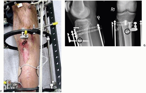 |
|
FIGURE 8-56 (continued) F.
Grade 5 pin tract infection with surrounding erythema, inflammation, and purulent drainage. Radiographs of this region must be examined for radiographic signs, suggestive of pin loosening. G. Radiographic evidence of pin sepsis and loosening includes pin sequestrum (white arrow) and cortical lucencies (black circle). |
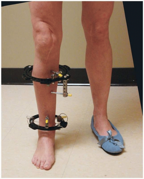 |
|
FIGURE 8-57
Prior to frame removal, all the connecting rods were removed and only the rings remain. The frame has been fully dynamized, and the patient was allowed to ambulate full weight bearing. The patient is instructed to be aware of any signs of pain or deformity, which would indicate incomplete healing. If this occurs, the connecting bars can easily be reapplied and the frame not removed at this time. |
practice of recycling external fixator components makes economic sense.
Dirschl and Smith reported on a single center’s experience with a reuse
program. Components in good repair were returned to the operating room
stock for reuse, whereas those showing signs of wear were discarded. No
component was used more than three times. The institution charged
patients a “loaner fee” equal to the hospital’s cost for the
inspection, processing, and recycling of fixator components. The mean
hospital cost for a fixator decreased 34% as a result of this program.
There were no differences in the rates of reoperation or complications
before and after institution of the reuse program. No patient had
mechanical failure of a new or reused component.63,64,132
A thorough examination of clinically removed frames, including static
mechanical testing, has shown no reduction in performance or
catastrophic mechanical failure of recycled parts that showed no visual
signs of wear. The potential cost savings, combined with the documented
safety of recycled components, makes reuse of these devices attractive.
companies that perform in-house reprocessing of single use medical
devices (external fixator components). The U.S Food and Drug
Administration (FDA) announced new guidelines for
hospitals
as well as third party reprocessing companies that now holds them to
the same rigorous premarket submission requirements as manufacturers.
For every device a hospital wants to reprocess, it must submit
information to the FDA that demonstrates the safety and effectiveness
of that device following reprocessing. This means that hospitals now
face tough choices, with a wide range of factors to consider, such as
cost liability, quality assurance, and device tracking. Since this
ruling went into effect, many hospitals have determined that they lack
the resources to meet the arduous premarket submission requirements
(510K approval). Hospitals that performed their own reprocessing have
been forced to decide whether to continue to recycle at great expense,
stop using reprocessed devices, or outsource to a third party
preprocessor. Many have decided to outsource the service.
company, can result in cost savings over the purchase price of new
fixator components. Data currently suggest that this does not
compromise a hospital’s standard of care or patient outcomes. A recent
study at Boston University evaluated reuse of reprocessed external
fixation frames at the time of removal, for efficacy of function and
potential complications of their use such as pin tract infections, loss
of fixation, or loosening of components.218
The authors found no statistical differences in the incidence of pin
tract infections, loss of fixation, or loosening of the components,
compared with those patients treated with new fixators. Their study
demonstrated that this type of reuse program was safe and effective
with a potential savings of 25% compared with the cost of all new
frames.
redeployment in hospital stock. Horwitz and collegues, using a
conservative pass rate and the assumption of a maximum of three
recertifications for each component, calculated the total potential
hospital savings on external fixation components when this program was
instituted.110 Components were
returned to the original manufacturer for reprocessing. The first-pass
rate was 76% for initial reprocessing. The second-pass rate (i.e., the
rate for components that had already been recertified once and had been
sent for a second recertification) was 83%. On the basis of a
conservative pass-rate estimate of 75%, the predicted average number of
uses of a recyclable component was 2.7. The recertified components were
sold back to their institution at 50% of the original price. Because
carbon-fiber bars and half-pins were not recycled, 85% of the charges
expended on new external fixation components were spent on portions of
the system that were recyclable. The potential total savings on
reusable components was found to be 32%, with a total savings of 27%
for the whole external fixation system. The investigators noted that no
recertified components failed in clinical use over the course of the
study.
associated with a manufacturer-based testing and recertification
program. However, issues of voluntary participation in reuse programs
by the patient as well as informed consent of the use of reprocessed
components, component ownership, and the impact of savings on patient
charges have yet to be worked out by individual institutions.
inflammation, chronic infection, loosening, and metal fatigue failure.
Most authors agree that infection rates from external fixation pins
have steadily decreased, as pin technology has increased, but are still
very far from zero.60 The rates of
frank pin tract infection have been chronicled as antidotal
observations mentioned off hand in many studies regarding external
fixation given as the basis for a pin tract infection and pin failure.
The major problem inherent in all external fixator studies has been the
definition of what exactly an infected pin site consists of. Histologic
examination of the tissues surrounding the inflamed pin site might lead
to the conclusion that almost every pin tract is infected. The most
common wire and pin site complications are now graded by the
classification as described by Dahl et al55 (Table 8-1).
marginal inflammation; however, no drainage is apparent and treatment
requires more frequent pin care consisting of daily cleansing with mild
soap or half-strength peroxide and saline solution.
consists of serous or seropurulent drainage in concert with redness,
inflammation, and radiographs demonstrating osteolysis of both the near
and far cortices (see Fig. 8-56E). Once
osteolysis is visible demonstrating bicortical involvement, removal of
the offending pin should be carried out immediately. Local soft tissue
debridement of the pin tract with peroxide or other astringent irrigant
should be performed. Formal surgical management is unnecessary as long
as there is no obvious radiolucencies noted on the plain radiographs at
the side of osteolysis (Fig. 8-56G)
inflammation consists of inflamed purulent drainage and osteolysis, as
well as sequestrum noted around these abscesses within the medullary
canal. Deep-seated infection is present, and this requires formal
irrigation and debridement procedures with delivery of culture-specific
antibiotics (Fig. 8-56F). In an effort to avoid
collapse of the external fixation construct and the establishment of
biomechanical frame instability, pin exchange should be carried out in
conjunction with the pin removal process.
techniques, the problem of premature consolidation is most commonly
diagnosed as a failure of the corticotomy site to open and lengthen
following initiation of distraction. In most instances, the problem is
actually an incomplete osteotomy rather than the premature healing of
the osteotomy site.1,112,242
When this occurs in the tibia, it is a failure to completely
osteotomize the posterior lateral cortex. This complication occurs
primarily with surgeons who do not have a large amount of experience in
performing percutaneous corticotomy techniques. Most experienced
surgeons will perform the corticotomy and then manually distract the
corticotomy site acutely for 1 to 2 mm under fluoroscopic control to
ensure that the corticotomy is complete and can manually
be
distracted. Using the fixator pins half above and below the corticotomy
as joysticks, the limb segments can be counterrotated one against the
other under fluoroscopy to ensure that a complete osteotomy has
occurred.1,94,95,96,112,242
|
TABLE 8-1 DAHL Pin Site Classification
|
|||||||||||||||||||||||||||||||||||
|---|---|---|---|---|---|---|---|---|---|---|---|---|---|---|---|---|---|---|---|---|---|---|---|---|---|---|---|---|---|---|---|---|---|---|---|
|
pediatric population where distraction must begin much sooner compared
with a mature patient. It is usually due to a prolonged latency period
allowing significant callus formation to bridge across the corticotomy
site. This is seen clinically, when examining the frame and seeing
excessive deflection of the wires or half-pins with a concomitant lack
of a distraction gap on radiography; if this is recognized early in the
treatment phase, continued slow distraction can be carried out until
the premature area of consolidation ruptures.1,112
The patient should be warned, however, that he may feel or hear an
audible ache, snap, or pop in the limb with sudden pain and concomitant
swelling. Should this occur, the patient should immediately reverse the
distraction and compress the region until the pain has subsided. If the
patient continues to distract following the fracture of the premature
consolidation zone, significant diastasis in the distraction gap will
be created causing rupture of the neovascular channels. This may result
in the formation of cysts with incomplete regenerate formation and
possible regenerate failure.1,15,16,112,113,114,174
of the premature consolidation, the patient should be returned to the
operating room where closed manipulation can sometimes be successful in
achieving complete corticotomy. Should this fail, a repeat corticotomy
should be carried out.
includes disruption of the periosteum and soft tissues during
corticotomy, too rapid a distraction, and frame instability.15,16,112,113,114
in accordance with the radiographic visualization of the regenerate
bone including the formation of the interzone and longitudinal
orientation of trabecular bone. Any evidence of disruption or nonlinear
orientation of the trabecular bone should be a clear sign that frame
instability has occurred. Each pin, wire, and ring connection should be
checked and, if necessary, additional pins or wires added to assure
adequate frame stability. This will help to avoid formation of
intercalary cartilaginous elements.
removal of the apparatus usually presents as a gradual deviation of the
limb. This often occurs as a result of the patient and treating surgeon
becoming “frame weary,” which results in premature frame removal prior
to complete healing of the regenerate or fracture.1,112
Certainly, one should always error on the conservative side and leave
the frame on for an extended period of time to ensure that the fracture
has healed.
usually the result of incomplete healing. What is more common is
fracturing through an osteoporotic stress fracture or through a
previous pin or wire hole site.
usually leads to an unsatisfactory outcome unless collapse is detected
early and the frame reapplied. Untreated, the resulting malunion
requires secondary osteotomy procedures.
fracture site refractures, can usually be treated with a cast if
detected early before significant malalignment occurs. However, in
complex cases, frame reapplication is required.
distraction. This can occur over an extended period of time such as the
use of an ankle bridging monotube fixator or temporary traveling
traction spanning the knee or ankle.208
A common complication when using lower extremity external fixators is
the development of equinus contractures of the foot and ankle. To
prevent this, prophylaxis should be encouraged by spanning the tibial
frame down onto the forefoot in a neutral position.
becomes relatively short compared with that of the newly lengthened
bone. Thus, tibial lengthening or bone transport can cause flexion
contractures at the knee and equinus contractures of the ankle.
Measures should be taken to provide prophylaxis against severe muscle
contractures when dealing with correction of leg length discrepancy.1,112 This also occurs during the correction of malunions or nonunions where, following the deformity correction,
relative length is restored. Preventive measures include avoiding
transfixion of tendons and maximizing muscle excursion before placing
transfixion wires or half-pins. Physical therapy throughout the course
of treatment is helpful as is splinting and maintaining a plantigrade
foot in neutral and the knee in full extension when the patient is at
rest.
result in improvements in pin and frame technology. External fixation
frames can now remain in place for prolonged periods of time without
degradation in the pin-bone interface. Simplified frame mountings have
extended the indications for use of these devices, not only for acute
fracture management but also for the reconstruction of complex
posttraumatic conditions. Cutting edge technologies such as web-based
software interfacing with digital radiographs, combined with
uncomplicated frame adjustments, can now produce anatomic restoration
of limbs that previously could not be achieved with external devices.
External fixation continues to provide a powerful means to treat a
variety of challenging conditions as the ultimate noninvasive tool.
Group, Maiocchi AB, Aronson J, eds. Operative Principles of Ilizarov:
Fracture Treatment, Nonunion, Osteomyelitis, Lengthening, Deformity
Correction. Baltimore, MD: Williams & Wilkins, 1991.
MJ. Taylor Spatial Frame in the treatment of pediatric and adolescent
tibial shaft fractures. J Pediatr Orthop 2006;26:164-170.
AM, Burton M, Hashmi M, et al. Outcome of complex fractures of the
tibial plateau treated with a beam-loading ring fixation system. J Bone
Joint Surg Br 2003;85B: 691-699.
AM, Saleh M, Bolongaro S, et al. The strength of different fixation
techniques for bicondylar tibial plateau fractures: a biomechanical
study. Clin Biomech (Bristol, Avon) 2003;18:864-870.
AM, Yang L, Hashmi M, et al. Bicondylar tibial plateau fractures
managed with the Sheffield Hybrid Fixator. Biomechanical study and
operative technique. Injury 2001; 32 suppl 4:SD86-SD91.
Y, Wagenknecht M, Donkerwolcke M, et al. External fixation pin: an in
vitro general investigation. Orthopedics 1987;10:1507-1516.
V, Ono CM, Antoci V Jr, et al. Pin-tract infection during limb
lengthening using external fixation. Am J Orthop 2008;37:E150-E154.
M, Yalcin H, Tarakcioglu N, et al. The effects of dynamization and
destabilization of the external fixator on fracture healing: a
comparative biomechanical study in dogs. Orthopedics 2002;25:521-524.
HT, Chao EY. Bone-healing patterns affected by loading, fracture
fragment stability, fracture type, and fracture site compression. Clin
Orthop 1993;8-17.
HT, Kelly PJ, Lewallen DG, et al. The effects of physiologic dynamic
compression on bone healing under external fixation. Clin Orthop
1990;260-273.
HT, Markel MD, Chao EY. Cortical bone reactions at the interface of
external fixation half-pins under different loading conditions. J
Trauma 1993;35:776-785.
J, Harp JH Jr. Mechanical considerations in using tensioned wires in a
transosseous external fixation system. Clin Orthop 1992;23-29.
J, Harrison B, Boyd CM, et al. Mechanical induction of osteogenesis:
the importance of pin rigidity. J Pediatr Orthop 1988;8:396-401.
J, Johnson E, Harp JH. Local bone transportation for treatment of
intercalary defects by the Ilizarov technique. Biomechanical and
clinical considerations. Clin Orthop 1989;71-79.
I, Brogren E, Larsson GU, et al. Wrist-bridging versus nonbridging
external fixation for displaced distal radius fractures: a randomized
assessor-blind clinical trial of 38 patients followed for 1 year. Acta
Orthop 2006;77:445-453.
P, Burger J, Schorlemmer S, et al. Shear movement at the fracture site
delays healing in a diaphyseal fracture model. J Orthop Res
2003;21:1011-1017.
P, Claes L, Hanselmann KF, et al. Increase of stability in external
fracture fixation by hydroxyapatite-coated bone screws. J Appl Biomater
1995;6:99-104.
P, Merk J, Wolf S, et al. Mechanical stimulation by external
application of cyclic tensile strains does not effectively enhance bone
healing. J Orthop Trauma 2001;15: 54-60.
F, Johnson WD, Koch TW, et al. Bending Stiffness of Unilateral and
Bilateral Fixator Frames. Clin Orthop 1983;178:103-110.
M, Zlowodzki M, Tornetta P 3rd, et al. Intramedullary nailing following
external fixation in femoral and tibial shaft fractures. J Orthop
Trauma 2005;19: 140-144.
TL, Schneider E, Rahn BA, et al. The effect of radial preload on the
implant-bone interface: a cadaveric study. J Orthop Trauma
1989;3:323-332.
MJ, Holmes C, Vossoughi J, et al. Comparison of the Howmedica and
Synthes military external fixation frames. J Orthop Trauma
1994;8:119-126.
M, Marsh JL, Brown TD. Articulated external fixation of the ankle:
minimizing motion resistance by accurate axis alignment. J Biomech
1999;32:63-70.
BT, Chao EY. The mechanical performance of the standard Hoffmann-Vidal
external fixation apparatus. J Bone Joint Surg Am 1982;64A:566-473.
MR, O’Connor DP, Crouch CC, et al. Ilizarov treatment of infected
nonunions of the distal humerus after failure of internal fixation: an
outcomes study. J Orthop Trauma 2007;21:178-184.
PLO, Sermon A. From unstable internal fixation to biological
osteosynthesis: a historical overview of operative fracture treatment.
Acta Chir Belg 2004;104:396 -400.
DG, Samchukov ML, Birch JG. Stabilization of a short juxta-articular
bone segment with a circular external fixator. J Pediatr Orthop B
2002;11:143-149.
VL, Larsson S, Kim W, et al. Mechanical performance of the
Monticelli-Spinelli external fixation system. Clin Orthop 1994;257-266
VL, Piza G, Navarro A. Hydroxyapatite coating of external fixation pins
to decrease axial deformity during tibial lengthening for short
stature. J Bone Joint Surg Am 2003; 85A:1527-1531.
M, Soutis C, Oni OO. Pin-hole shear stresses generated by conical and
standard external fixation pins. Biomaterials 1993;14:876-878.
KD, Bynum J, Goucher N. Rates of refracture associated with external
fixation in pediatric femur fractures. Am J Orthop 2005;34:439-444;
discussion 444.
EY, Kasman RA, An KN. Rigidity and stress analyses of external fracture
fixation devices—a theoretical approach. J Biomech 1982;15:971-983.
S, Patil N, Bagaria V, et al. Open intercondylar fractures of the
distal humerus: Management using a miniexternal fixator construct. J
Shoulder Elbow Surg 2008; 17:465-470.
EP, Bosse MJ, Robb G. Reconstruction of large diaphyseal defects,
without free fibular transfer, in grade IIIB tibial fractures. J Bone
Joint Surg 1989;71A:994-1002.
L, Eckert-Hubner K, Augat P. The effect of mechanical stability on
local vascularization and tissue differentiation in callus healing. J
Orthop Res 2002;20:1099-105.
EM, Roe SC. In vitro biomechanical and histological assessment of pilot
hole diameter for positive-profile external skeletal fixation pins in
canine tibiae. Vet Surg 1996;25:453-462.
JC, Cannon LB, Stapley SA, et al. Fluid accumulation and the rapid
spread of bacteria in the pathogenesis of external fixator pin track
infection. Injury 2001;32: 377-381.
AR, Lewis DD, Murphy ST, et al. Effects of ring diameter and wire
tension on the axial biomechanics of four-ring circular external
skeletal fixator constructs. Am J Vet Res 2001;62:1025-1030.
JL, Evans M, Harris JD, et al. The measurement of stiffness of
fractures treated with external fixation. Eng Med 1987;16:229-232.
LE, Jacobs RR, McKenzie EB, et al. Biomechanical studies of an anterior
pelvic external fixation frame intended for control of vertical shear
fractures. South Med J 1986;79:815–817.
P, Defoort K, Lammens J, et al. Management of a large posttraumatic
skin and bone defect using an Ilizarov frame. Acta Orthop Belg
2006;72:214–218.
LA, Roe SC, Abrams CF Jr. Holding power of different pin designs and
pin insertion methods in avian cortical bone. Vet Surg 1998;27:301-306.
ES, DeBerardino TM, Brooks DE, et al. Antimicrobial efficacy of
external fixator pins coated with a lipid stabilized
hydroxyapatite/chlorhexidine complex to prevent pin tract infection in
a goat model. J Trauma 2001;50:1008-1014.
Rocca GJ, Crist BD. External fixation versus conversion to
intramedullary nailing for definitive management of closed fractures of
the femoral and tibial shaft. J Am Acad Orthop Surg 2006;14(10
suppl):S131-S135.
CR, Wolinsky P, Shepherd E, et al. The use of hinged external fixation
to provide additional stabilization for fractures of the distal
humerus. J Orthop Trauma 2007;21: 323-329.
SD, Cornelissen S, Jossan S, et al. A biomechanical comparison of
fragmentspecific fixation and augmented external fixation for
intra-articular distal radius fractures. J Hand Surg [Am]
2002;27:953-964.
PJ, Vickaryous B, Conley E, et al. A comparison of two military
temporary femoral external fixators. Clin Orthop 2003;176-183.
J, Hayes P, Fenlon G. Experimental analysis of effects of pin
pretensioning on external fixator rigidity. Arch Orthop Trauma Surg
1988;107:377-380.
FL, Finlay JB. Universal joint slippage as a cause of Hoffmann
half-frame external fixator failure [erratum in J Biomed Eng
1993;15:174]. J Biomed Eng 1992;14: 509-515.
GN, Sollmann M, Sporrer S, et al. Interfragmentary motion in tibial
osteotomies stabilized with ring fixators. Clin Orthop 2002;163-172.
CC. Staged reconstruction of complex open tibial fractures using
Hoffmann external fixation: clinical decisions and dilemmas. Clin
Orthop 1983;178:130-161.
KA, Bazzi J, McLaurin TM, et al. The effect of knee-spanning external
fixation on compartment pressures in the leg. J Orthop Trauma
2008;22:680-685.
KA, Paksima N, Puopolo S, et al. Treatment of external fixation pins
about the wrist: a prospective, randomized trial. J Bone Joint Surg Am
2006;88A:349-354.
M, Bialik V, Katzman A. Correction of deformities in children using the
Taylor spatial frame. J Pediatr Orthop B 2006;15:387-395.
Hayek T, Daher AA, Meouchy W, et al. External fixators in the treatment
of fractures in children. J Pediatr Orthop B 2004;13:103-109.
T, Grass R, Biewener A, et al. [Advantages of minimally invasive
reposition, retention, and hybrid Ilizarov fixation for tibial pilon
fractures with particular emphasis on C2/C3 fractures]. Unfallchirurg
2004;107:273-284.
WF, Eady JL, Burchardt H. Autogenous cortical bone grafts in the
reconstruction of segmental skeletal defects. J Bone Joint Surg Am
1980;62A:1039-1058.
C, Burri C, Claes L, et al. Treatment by external fixation of open
fractures associated with severe sof tissue damage of the leg.
Biomechanical principles and clinical experience. Clin Orthop
1983;80-88.
DS, Madan SS, Koval KJ, et al. Correction of tibia vara with six-axis
deformity analysis and the Taylor Spatial Frame. J Pediatr Orthop
2003;23:387-391.
DA. Skeletal stabilization with a multiplane external fixation device.
Design rationale and preliminary clinical experience. Clin Orthop
1983;:50-62.
DC, Foels WS, Pedersen DR, et al. An articulated ankle external
fixation system that can be aligned with the ankle axis. Iowa Orthop J
1995;15:197-203.
DC, Sommers MB, Kam BC, et al. Knee stability after articulated
external fixation. Am J Sports Med 2005;33:1735-1741.
T, Ristiniemi J, Hyvonen P, et al. Nonbridging external fixation in the
treatment of unstable fractures of the distal forearm. Arch Orthop
Trauma Surg 2003;123: 349-352. Epub 2003 Jun 14.
MJ, Nork SE. Stabilization of unstable pelvic fractures with
supra-acetabular compression external fixation. J Orthop Trauma
2007;21:269-273.
A, Phillips JH. The effects of varying pilot hole size on the holding
power of miniscrews and microscrews. Plast Reconstr Surg
1995;95:1165-1169.
J, Tornetta P 3rd, Tiburzi D, et al. Tension wire position for hybrid
external fixation of the proximal tibia. J Orthop Trauma
2000;14:502-504.
JE, Kelly-Hahn J, Carpenter CJ, et al. Pin site care during external
fixation in children: results of nihilistic approach. J Pediatr Orthop
2000;20:163.
AE, Cunningham JL, Kenwright J. Strain rate and timing of stimulation
in mechanical modulation of fracture healing. Clin Orthop 1998;(355
suppl):S105-S115.
AE, Watkins PE, Rigby HS, et al. The role of fixator frame stiffness in
the control of fracture healing. An experimental study. J Biomech
1993;26:1027-1035.
JC, DaSilva MF, Viegas SF, et al. Kinematics of the wrist with a new
dynamic external fixation device. Clin Orthop 2001;226-234.
G, Jupiter JB, Gierer P, et al. Fractures of the distal radius treated
with a nonbridging external fixation technique using multiplanar
K-wires. J Hand Surg [Am] 2005;30: 960-968.
SA. Complications of External Skeletal Fixation: Causes Prevention, and
Treatment. Springfield, IL: Charles C Thomas, 1981.
SA, Jackson JM, Wall DM, et al. Management of segmental defects by the
Ilizarov intercalary bone transport method. Clin Orthop
1992;280:136-142.
GJ, Kumar S, Prpa B. Placement of half-pins for supra-acetabular
external fixation: an anatomic study. Clin Orthop 2003;269-273.
GJ. Temporary external fixation for the management of complex intra-and
periarticular fractures of the lower extremity. J Orthop Trauma
2002;16:678-685.
OP, ed. Orthopaedic Surgery in the Mediterranean Theatre of Operations.
Washington, DC: Office of the Surgeon General, Department of the Army;
1957: 203-210. Bradford C, Wilson PD. Mechanical skeletal fixation in
war surgery, with a report of 61 cases. SGO 1942;75:486-476.
HH, Huntley JS, Madhok R. Different methods of external fixation for
treating distal radial fractures in adults. Cochrane Database Syst Rev
2008:CD006522.
T, Hontzsch D, Stohr E, et al. [How much are external fixator nuts
tightened in general practice?] Aktuelle Traumatol 1993;23:212-213.
MB, Wu JJ, Chao EY, et al. External skeletal fixation of canine tibial
osteotomies. Compression compared with no compression. J Bone Joint
Surg Am 1985;67:598-605.
PJ, Giannoudis PV, Probst C, et al. The risk of local infective
complications after damage control procedures for femoral shaft
fracture. J Orthop Trauma 2006;20: 181-189.
C, Jagodzinski M, Krettek C, et al. Hinged external fixation and closed
reduction for distal humerus fracture. Arch Orthop Trauma Surg
2006;126:188-191.
DS, Schabel KL, Higgins TF. The economic impact of reprocessing
external fixation components. J Bone Joint Surg Am 2007;89A:2132-2136.
DT, Bachus KN, Higgenbotham T. External fixation of the distal radius:
to predrill or not to predrill. J Hand Surg [Am] 2000;25:1064-1068.
GA. Transosseous osteosynthesis. In: Green S, ed. Theoretical and
Clinical Aspects of the Regeneration and Growth of Tissue. Berlin:
Springer Verlag, 1992.
GA. The tension-stress effect on the genesis and growth of tissues:
part II. The influence of the rate and frequency of distraction. Clin
Orthop 1989;263-285.
GA. The tension-stress effect on the genesis and growth of tissues:
part I. The influence of stability of fixation and soft-tissue
preservation. Clin Orthop 1989; 249-281.
M, Haasper C, Knobloch C, Krettek C [Treatment of chronic knee
dislocation with an external fixator]. Unfallchirurg 2005;108:597-600.
RA, Egkher E, Wielke B. Comparison of the mechanical performance of
three types of unilateral, dynamizable external fixators. An
experimental study. Arch Orthop Trauma Surg 1994;113:271-275.
JA, Prat J, Vera P, et al. Biomechanical consequences of callus
development in Hoffmann, Wagner, Orthofix, and Ilizarov external
fixators. J Biomech 1992;25: 995-1006.
T, Tsuchiya H, Sakurakichi K, et al. Reconstruction with distraction
osteogenesis for juxta-articular nonunions with bone loss. J Trauma
2005;58:1213-1222.
IA, Miles AW, Cunningham JL, et al. Axial preload in external fixator
half-pins: a preliminary mechanical study of an experimental bone
anchorage system. Clin Biomech (Bristol, Avon) 1999;14:69-73.
J, Richardson JB, Cunningham JL, et al. Axial movement and tibial
fractures. A controlled randomised trial of treatment. J Bone Joint
Surg Br 1991;73B:654-659.
C, Voor MJ, Seligson D. Fracture site motion with Ilizarov and “hybrid”
external fixation. J Orthop Trauma 1998;12:21-26.
HJ, Agel J, McKee MD, et al. A randomized, controlled trial of distal
radius fractures with metaphyseal displacement but without joint
incongruity: closed reduction and casting versus closed reduction,
spanning external fixation, and optional percutaneous K-wires. J Orthop
Trauma 2006;20:115-121.
J, Wigg AE, Walker RW, et al. Intra-articular fractures of the distal
radius: a prospective randomized controlled trial comparing static
bridging and dynamic nonbridging external fixation. J Hand Surg [Br]
2003;28:417-421.
M, Schemitsch EH, Harrington RM, et al. Comparative biomechanical
evaluation of different external fixation sidebars: stainless-steel
tubes versus carbon fiber rods. J Orthop Trauma 1996;10:470-475.
D, Chen CM, Chiu FY, et al. Reconstruction of juxta-articular huge
defects of distal femur with vascularized fibular bone graft and
Ilizarov’s distraction osteogenesis. J Trauma 2007;62:166-173.
S, Kim W, Caja VL, et al. Effect of early axial dynamization on tibial
bone healing: a study in dogs. Clin Orthop 2001;240-251.
C, Bledsoe G, Watson JT. Circular external fixation frames with
divergent half-pins: a pilot biomechanical Study. Clin Orthop Relat Res
2008;466:2933-2939.
A, Fodor L, Keren Y, et al. External fixation for temporary
stabilization and wound management of an open pelvic ring injury with
extensive soft tissue damage: case report and review of the literature.
J Trauma 2008;65:715-718.
A, Ullmann Y, Stein H, et al. Using the Ilizarov external fixation
device for skin expansion. Ann Plast Surg 2000;45:535-537.
A, Temple J, Santy J. Pin site care for preventing infections
associated with external bone fixators and pins. Cochrane Database Syst
Rev 2008;CD004551.
F, Kwok HY, Pun TS, et al. Limited open reduction and Ilizarov external
fixation in the treatment of distal tibial fractures. Injury
2004;35:278-283.
F, Tu YK, Chew WY, et al. Comparison of external and percutaneous pin
fixation with plate fixation for intra-articular distal radial
fractures. A randomized study. J Bone Joint Surg Am 2008;90A:16-22.
DG, Chao EY, Kasman RA, et al. Comparison of the effects of compression
plates and external fixators on early bone-healing. J Bone Joint Surg
Am 1984;66A: 1084-1091.
KM, Breidenbach L, Stader O. The Stader reduction splint for treating
fractures of the shafts of the long bones. Ann Surg 1942;116:623-631.
DW, Nork S, Abruzzo FM. Correlation of shear to compression for
progressive fracture obliquity. Clin Orthop Relat Res
2008;466:2947-2954.
G, Toksvig-Larsen S, Moroni A. Hydroxyapatite coating of threaded pins
enhances fixation. J Bone Joint Surg Br 1997;79B:487-479.
A, Pullen C, Deromedis B, et al. Knee arthrodesis after infected total
knee arthroplasty using the Ilizarov method. Clin Orthop 2001;143-149.
AD, Gellman H. Five-pin external fixation and early range of motion for
distal radius fractures. Orthop Clin North Am 2001;32:329-335, ix.
JS, Coupe KJ, Milner R, et al. Long-term bactericidal properties of a
gentamicincoated antimicrobial external fixation pin sleeve. J Bone
Joint Surg Am 2003;85A(suppl 4):129-131.
JM, Roe SC. Biomechanical comparison of the trocar tip point and the
hollow ground tip point for smooth external skeletal fixation pins. Vet
Surg 1998;27:423-428.
C, Guillen M, Lopez G. Treatment of two- and three-part fractures of
the proximal humerus using external fixation: a retrospective
evaluation of 62 patients. Acta Orthop 2006;77:275-278.
T, Nakamura K, Ohnishi I, et al. Sliding performance of unilateral
external fixators for tibia. Med Eng Phys 1998;20:66-69.
LS, Green CA, Goldstein SA. The thermal effects of skeletal
fixation-pin insertion in bone. J Bone Joint Surg Am 1984;66A:1077-1083.
DK, Dougall TW, Pool RD, et al. Augmentative Ilizarov external fixation
after failure of diaphyseal union with intramedullary nailing. J Orthop
Trauma 2002;16: 491-497.
AJ, Saleh M, Yang L. Techniques for improving stability in oblique
fractures treated by circular fixation with particular reference to the
sagittal plane. J Bone Joint Surg Br 2005;87B:868-872.
A, Caja VL, Maltarello MC, et al. Biomechanical, scanning electron
microscopy, and microhardness analyses of the bone-pin interface in
hydroxyapatite coated versus uncoated pins. J Orthop Trauma
1997;11:154-161.
A, Cadossi M, Romagnoli M, et al. A biomechanical and histological
analysis of standard versus hydroxyapatite-coated pins for external
fixation. J Biomed Mater Res B Appl Biomater 2008;86B:417-421.
A, Faldini C, Marchetti S, et al. Improvement of the bone-pin interface
strength in osteoporotic bone with use of hydroxyapatite-coated tapered
external-fixation pins. A prospective, randomized clinical study of
wrist fractures. J Bone Joint Surg Am 2001; 83A:717-721.
A, Faldini C, Pegreffi F, et al. Fixation strength of tapered versus
bicylindrical hydroxyapatite-coated external fixation pins: an animal
study. J Biomed Mater Res 2002;63:61-64.
A, Faldini C, Pegreffi F, et al. Dynamic hip screw compared with
external fixation for treatment of osteoporotic pertrochanteric
fractures. A prospective, randomized study. J Bone Joint Surg Am
2005;87A:753-759.
A, Heikkila J, Magyar G, et al. Fixation strength and pin tract
infection of hydroxyapatite-coated tapered pins. Clin Orthop
2001;209-217.
A, Vannini F, Mosca M, et al. State of the art review: techniques to
avoid pin loosening and infection in external fixation. J Orthop Trauma
2002;16:189-195.
RY, Chand Y, Matiko JD, et al. External fixators for wrist fractures: a
biomechanical and clinical study. J Hand Surg [Am] 1985;10(6 Pt
1):845-851.
SJ, Helfet DL, Rozbruch SR. Temporary intentional leg shortening and
deformation to facilitate wound closure using the Ilizarov/Taylor
spatial frame. J Orthop Trauma 2006;20:419-424.
J, Ring D, Lozano-Calderon S, et al. Interposition arthroplasty of the
elbow with hinged external fixation for post-traumatic arthritis. J
Shoulder Elbow Surg 2008;17: 459-464.
KJ, Price CT. Pearls and pitfalls of deformity correction and limb
lengthening via monolateral external fixation. Iowa Orthop J
1996;16:58-69.
S, Frerichmann U, Armsen N, et al. [Is use of the fixateur externe no
longer indicated for the treatment of unstable radial fracture in the
elderly?] Unfallchirurg 2006;109:1050-1057.
OO, Capper M, Soutis C. A finite element analysis of the effect of pin
distribution on the rigidity of a unilateral external fixation system.
Injury 1993;24:525-527.
OO, Capper M, Soutis C. External fixation of upper limb fractures: the
effect of pin offset on fixator stability. Biomaterials 1995;16:263-264.
GL, Frankel VH, Kummer FJ. The effect of wire configuration on the
stability of the Ilizarov external fixator. Clin Orthop 1992;:299-302.
D, Lamm BM, Katsenis D, et al. Treatment of malunion and nonunion at
the site of an ankle fusion with the Ilizarov apparatus. Surgical
technique. J Bone Joint Surg Am 2006;88A(suppl 1, pt 1):119-134.
AD, Roberts CS, Seligson D, et al. Pin tract infection with
contemporary external fixation: how much of a problem? J Orthop Trauma
2003;17:503-507.
AA, Smith WR, Silva S, et al. Treatment of distal femur and proximal
tibia fractures with external fixation followed by planned conversion
to internal fixation. J Trauma 2008;64:736-739.
SH, O’Connor K, McKellop H, et al. The influence of active shear or
compressive motion on fracture-healing. J Bone Joint Surg Am
1998;80A:868-878.
C. A new apparatus for the fixation of bones after resection and in
fractures with a tendency to displacement. Trans Am Surg Assoc
1897;15:251-256.
C. Further observations regarding the use of the bone clamp in ununited
fractures with malunion and recent fractures with a tendency to
displacement. Ann Surg 1898;27:59-67.
MJ, Cole JD. Two-staged delayed open reduction and internal fixation of
severe pilon fractures. J Orthop Trauma 1999;13:85-91.
LM. External skeletal fixation for the treatment of fractures. In:
Peltier LM, ed. Fractures: A History and Iconography of Their
Treatment. San Francisco: Norman Publishing; 1990:183-196.
MH, Sarna S, Paavolainen P, et al. Short-term external support promotes
healing in semirigidly fixed fractures. Clin Orthop 1997;157-163.
O, Geleng P, Zaspel J, et al. Titanium alloy pins versus stainless
steel pins in external fixation at the wrist: a randomized prospective
study. J Trauma 2008;64: 1275-1280.
A, Chao EY. Mechanical performance of Ilizarov circular external
fixators in comparison with other external fixators. Clin Orthop
1993;61-70.
KJ, Wolinsky PR, Pienkowski D, et al. Comparative biomechanics of
hybrid external fixation. J Orthop Trauma 1999;13:418-425.
LE, Bhaskar AR, Cole WG, et al. Treatment of open femur fractures in
children: comparison between external fixator and intramedullary
nailing. J Pediatr Orthop 2007;27:748-750.
M, Khodadadyan C, Maitino PD, et al. Nonunion of the humerus following
intramedullary nailing treated by Ilizarov hybrid fixation. J Orthop
Trauma 1998;12: 138-141.
D, Hotchkiss RN, Guss D, et al. Hinged elbow external fixation for
severe elbow contracture. J Bone Joint Surg Am 2005;87A:1293-1296.
CS, Antoci V, Antoci V Jr, et al. The accuracy of fine wire tensioners:
a comparison of five tensioners used in hybrid and ring external
fixation. J Orthop Trauma 2004; 18:158-162.
CS, Dodds JC, Perry K, et al. Hybrid external fixation of the proximal
tibia: strategies to improve frame stability. J Orthop Trauma
2003;17:415-420.
R, Jackson Hutson J, et al. Tibiocalcaneal arthrodesis using the
Ilizarov technique in the presence of bone loss and infection of the
talus. Foot Ankle Int 2008;29: 1001-1008.
MJ, McFadyen I, Livingstone JA, et al. Computer hexapod assisted
orthopaedic surgery (CHAOS) in the correction of long bone fracture and
deformity. J Orthop Trauma 2007;21:337-342.
SR, Fragomen AT, Ilizarov S. Correction of tibial deformity with use of
the Ilizarov-Taylor spatial frame. J Bone Joint Surg Am 2006;88A(suppl
4):156-174.
SR, Pugsley JS, Fragomen AT, et al. Repair of tibial nonunions and bone
defects with the Taylor Spatial Frame. J Orthop Trauma 2008;22:88-95.
S, Weitzman AM, Watson JT, et al. Simultaneous treatment of tibial bone
and soft-tissue defects with the Ilizarov method. J Orthop Trauma
2006;20:197-205.
K, Tsuchiya H, Uehara K, et al. Ankle arthrodesis combined with tibial
lengthening using the Ilizarov apparatus. J Orthop Sci 2003;8:20-25.
M, Rees A. Bifocal surgery for deformity and bone loss after lower-limb
fractures. Comparison of bone-transport and compression-distraction
methods. J Bone Joint Surg Br 1995;77:429-434.
FA, Burny F, Chao EY. Biomechanical properties and design
considerations in upper extremity external fixation. Hand Clin
1993;9:543-553.
K, Wolter D, Kortmann HR. Fracture reduction and deformity correction
with the hexapod Ilizarov fixator. Clin Orthop 1999;186-195.
WH Jr, Froimson AI, Brooks DB, et al. External fixator pin insertion
techniques: biomechanical analysis and clinical relevance. J Hand Surg
[Am] 1991;16:560-563.
D, Donald GD, Stanwyck TS, et al. Consideration of pin diameter and
insertion technique for external fixation in diaphyseal bone. Acta
Orthop Belg 1984;50:441-450.
AH, Cunningham JL, Kenwright J. The forces which develop in the tissues
during leg lengthening. A clinical study. J Bone Joint Surg Br
1996;78B:979-983.
M, Sanders R, DiPasquale T, et al. A staged protocol for soft tissue
management in the treatment of complex pilon fractures. J Orthop Trauma
1999;13:78-84.
CM, Kreuz FP, Jones DT. End results of treatment of fresh fractures by
the use of the Stader apparatus. J Bone Joint Surg 1944;26:471-474.
J, Egan J. Computerized analysis of pin geometry. In: Coombs R, Green
SA, Sarmeinto A, eds. External Fixation and Functional Bracing. London:
Orthotext, 1989: 129-135.
M, Pfeiffer M, Kotz R, et al. Lower limb deformities in children:
two-stage correction using the Taylor spatial frame. J Pediatr Orthop B
2003;12:123-128.
MB, Fitzpatrick DC, Kahn KM, et al. Hinged external fixation of the
knee: intrinsic factors influencing passive joint motion. J Orthop
Trauma 2004;18:163-169.
PG, VanderSchilden JL. Minimal internal and external fixation in the
treatment of open tibia fractures. Clin Orthop 1983;96-102.
DF, Dahl M, Louie K, et al. Management of late-onset tibia vara in the
obese patient by using circular external fixation. J Pediatr Orthop
1997;17:691-694.
EJ, Banerjee D, Kummer FJ, et al. Evaluation of a novel, nonspanning
external fixator for treatment of unstable extra-articular fractures of
the distal radius: biomechanical comparison with a volar locking plate.
J Trauma 2008;64:975-981.
G, Ruchholtz S, Zettl R, et al. Primary external fixation with
consecutive procedural modification in Polytrauma. Unfallchirurg
2002;105:315-321.
J, Santy J. Pin site care for preventing infections associated with
external bone fixators and pins. Cochrane Database Syst Rev
2008;CD004551.
AF, Claudi B, Pearce S, et al. Development of a variable stiffness
external fixation system for stabilization of segmental defects of the
tibia. J Orthop Res 1984;1:395-404.
KD, Paley D. Accuracy of correction of complex lower-extremity
deformities by the Ilizarov method. Clin Orthop 1994;102-110.
AJ, Patankar J. Open tibial fractures. Treatment by uniplanar external
fixation and early bone grafting. J Bone Joint Surg Br 1991;73B:448-451.
DB, Markolf KL, Cracchiolo A 3rd. External fixation in arthrodesis of
the ankle. A biomechanical study comparing a unilateral frame with a
modified transfixion frame. J Bone Joint Surg Am 1994;76A:1541-1544.
S, Bumbasirević M, Lesić A, et al. Ilizarov frame fixation without bone
graft for atrophic humeral shaft nonunion: 28 patients with a minimum
2-year follow-up. J Orthop Trauma 2007;21:549-556.
H, Uehara K, Abdel-Wanis ME, et al. Deformity correction followed by
lengthening with the Ilizarov method. Clin Orthop 2002;402:176-183.
DG, MacLeod MD, Sanders DW. High tibial osteotomy with use of the
Taylor Spatial Frame external fixator for osteoarthritis of the knee.
Can J Surg 2006; 49:245-250.
MJ, Abidi NA, Ishikawa SN, et al. Soft tissue injuries with the use of
safe corridors for transfixion wire placement during external fixation
of distal tibia fractures: an anatomic study. J Orthop Trauma
2001;15:555-559.
MV, Oganesian OV. Restoration of function in the knee and elbow with a
hinge-distractor apparatus. J Bone Joint Surg Am 1975;57A:591-600.
AM, Haddad SL, Kadakia A, et al. Extracapsular placement of distal
tibial transfixation wires. J Bone Joint Surg Am 2004;86A:988-993.
ZG, Peng CL, Zheng XL, et al. Force measurement on fracture site with
external fixation. Med Biol Eng Comput 1997;35:289-290.
JT. Nonunion with extensive bone loss: reconstruction with ilizarov
techniques and orthobiologics. Opin Tech Orthop 2009;18:95-107.
JT, Occhietti M, Parmar V. Rate of postoperative wound infections in
patients with pre-existing external fixators treated with secondary
open procedures. Presented at the Proceedings of the 15th Annual
Meeting Orthopaedic Trauma Association, Charlotte, NC, October 22-24,
1999.
JT, Karges DE, Cramer KE, et al. Analysis of failure of hybrid external
fixation techniques for the treatment of distal tibial pilon fractures.
Presented at the Proceedings of the 16th Annual Meeting Orthopaedic
Trauma Association, San Antonio, TX, October 12-14, 1999.
JT, Moed BR, Karges DE, et al. Pilon fractures: treatment protocol
based on severity of soft tissue injury. Clin Orthop 2000;375:78-90.
JT, Ripple S, Hoshaw SJ, et al. Hybrid external fixation for tibial
plateau fractures: clinical and biomechanical correlation. Orthop Clin
North Am 2002;33: 199-209.
MA, Mathias KJ, Maffulli N, et al. The effect of clamping a tensioned
wire: implications for the Ilizarov external fixation system. Proc Inst
Mech Eng [H] 2003; 217:91-98.
MA, Matthias KJ, Maffulli N, et al. Yielding of the clamped-wire system
in the Ilizarov external fixator. Proc Inst Mech Eng [H]
2003;217:367-374.
A, Toksvig-Larsen S, Lindstrand A. No difference between daily and
weekly pin site care: a randomized study of 50 patients with external
fixation. Acta Orthop Scand 2003;74:704-708.
EA, Rand JA, An KN, et al. The early healing of tibial osteotomies
stabilized by one-plane or two-plane external fixation. J Bone Joint
Surg Am 1987;69A:355-365.
H, Glockner R, Bail H, et al. Stiffness characteristics of composite
hybrid external fixators. Clin Orthop 2002;267-276.
MA, Marcellin-Little DJ, Roe SC. Influence of bolt tightening torque,
wire size, and component reuse on wire fixation in circular external
fixation. Vet Surg 2002;31: 571-576.
JJ, Shyr HS, Chao EY, et al. Comparison of osteotomy healing under
external fixation devices with different stiffness characteristics. J
Bone Joint Surg Am 1984;66A: 1258-1264.
G, Ishii Y, Matsuda Y, et al. Biomechanical characteristics of
nonbridging external fixators for distal radius fractures. J Hand Surg
[Am] 2008;33:322-326.
N, Nakase T, Kawabata H, et al. A technique of percutaneous
multidrilling osteotomy for limb lengthening and deformity correction.
J Orthop Sci 2000;5:104-107.
C, Atesalp AS, Demiralp B, et al. High-velocity gunshot wounds of the
tibial plafond managed with Ilizarov external fixation: a report of 13
cases. J Orthop Trauma 2003;17:421-429.
JR, Throckmorton TW, Bauer RM, et al. Management of acute complex
instability of the elbow with hinged external fixation. J Shoulder
Elbow Surg 2007;16:60-67.
S, Iacono F, Lo Presti M, et al. A new hinged dynamic distractor, for
immediate mobilization after knee dislocations: technical note. Arch
Orthop Trauma Surg 2007;Dec 6:78.
M, Prakash JS, Aggarwal NK. External fixation of complex femoral shaft
fractures. Int Orthop 2007;31:409-413. Epub 2006 Aug 15.