
stimulating electrode to outline the course of an underlying peripheral
nerve or neural plexus. Nerve mapping can serve as a surrogate method
to the use of conventional anatomical surface landmarks for the
performance of peripheral nerve blocks. Conventionally, blocks of
peripheral neural or plexuses have been performed following the
identification of previously described or published surface landmarks,
which serve as approximate starting points for invasive exploration
with a block needle. Exploration with the block needle proceeds until
the identification of an appropriate endpoint, following which
injection of local anesthetic results in a high rate of success. Two
types of such endpoints exist: 1) anatomical endpoints that rely on the
identification of anatomical structures that are closely related to the
nerve, and 2) functional endpoints that rely on neural function or
response to mechanical or electrical stimulation by the block needle.
Functional endpoints include mechanical paresthesia (sensory response to mechanical stimulation) as well as motor response to electrical stimulation, comprising the two most frequently utilized endpoints in peripheral or plexus blockade.
starting point for invasive needle exploration, independent of the
technique used. Anatomical landmarks have limitations. They vary from
patient to patient, and are dependent on patient size or body habitus.
Published anatomical landmarks often include measured angles and
distances in centimeters that are not normalized or adapted to patient
size or variations in anatomy. Such landmarks can only serve, at best,
as an approximation.
anatomical landmarks, involves the use of electrical nerve stimulation
and thus yields useful information prior to needle insertion. This
allows for prelocalization of the targeted nerve or plexus prior to
invasive search with the needle. Nerve mapping has in common with
ultrasonography or other imaging techniques the ability to yield
information noninvasively to facilitate nerve location. This chapter
focuses on the science of nerve stimulation, in particular
transcutaneous nerve stimulation for nerve mapping or prelocation of
nerves in adults. The recently published technique of indentation
percutaneous electrode guidance (PEG) of the block needle will be
discussed as it applies to enhancement of the concept of nerve mapping
and subsequent final location and injection of the targeted nerve or
plexus.
charge could result in an electrical stimulation and resulting muscular
contraction in 1780. However it was not until 1850 when the underlying
physiology was studied in depth by Von Helmholtz, who performed
numerous experiments using isolated nerve/muscle preparations. In 1912,
Perthes described the technique of electrical stimulation using a
selective peripheral nerve stimulator with a nickel-insulated needle to
assist in regional anesthetic neural blockade. Although there was
strong interest in regional anesthesia and anesthetic techniques in the
beginning of the twentieth century, this interest faded for a period. A
resurgence in regional anesthetic techniques occurred later in the
century, which has increased dramatically to the present day. In 1955,
Pearson was the first to use an insulated needle to successfully locate
motor nerves by electrical stimulation. In 1962, Greenblatt and Denson
used a self-built electrical nerve stimulator to assist in peripheral
nerve and plexus blocks. They demonstrated that the motor component of
mixed nerves could be stimulated without causing pain. In 1969, Magora,
using an electrical stimulator with an ammeter, determined that 0.5 mA
was a suitable stimulation threshold for successful blockade of the
obturator nerve. In 1980 Raj et al. re-introduced the idea of nerve
stimulation to assist in the performance of peripheral nerve blocks,
ushering in the modern era of the electrical nerve stimulator. A review
article was published in 1985 by Pither, et al. that covered the
experience to that date of the use of electrical nerve stimulators in
regional anesthesia, focusing on the characteristics of nerve
stimulators, needles, basic science, clinical technique, and
applications of the techniques.
modified electrocardiographic electrode with coupling gel that was used
to assist in the performance of interscalene block by prelocation of
the brachial plexus using transcutaneous stimulation. In 2002, Urmey
and Grossi first described the technique of percutaneous electrode
guidance. These investigators used a cylindrical electrically shielded
cutaneous electrode to map nerves by transcutaneous stimulation as well
as to guide the block needle to the targeted nerve by indentation of
the skin using the cylindrical electrode. Also in 2002, Bosenberg and
colleagues published a report that many superficial peripheral nerves
can be “mapped” prior to skin penetration by transcutaneous stimulation
in the 2 to 3.5 mA range. In 2003, Hadzic, et al. analyzed the
characteristics of a large number of various commercially available
nerve stimulators using an oscilloscopic analysis of the resulting
square waves. In 2004, the same investigators examined the significance
of anatomical placement of the ground lead as well as the relationship
between the electrical pulse amplitude (amperage) and pulse duration.
In 2006, Urmey and Grossi published the technique of sequential
electrical nerve stimulation, which used a series of alternating pulse
durations to increase feedback or information—motor responses—at a
distance from the nerve.
location involves the use of a peripheral nerve stimulator; that is, a
direct current (DC) “square-wave” impulse generator. Peripheral nerve
stimulators typically supply a constant electrical current, the
frequency (Hz), amplitude (mA), and pulse duration (ms) of which can be
manipulated in order to assist in location of motor or mixed
motor/sensory nerves. Depolarization of the nerve depends on the
distance from the electrical field generated at the tip of the
stimulating microelectrode needle, the electrical charge, and the
stimulation threshold of the targeted nerve. Depolarization and the
resulting action potentials will elicit a motor response and movement
of varying intensity.
essential components: an oscillator, a constant current generator, a
display, and capabilities to control stimulus, intensity, duration, and
frequency. The most modern stimulators involve a microprocessor
that
is programmed to control these parameters and ensure their accuracy.
Most modern units are constant current generators that ensure accurate
delivery of a constant current in the face of changes in electrical
impedance that occur between anode and cathode.
must be achieved. The electrical charge applied to the nerve is a
product of the current amplitude (mA) and the pulse duration in
milliseconds (ms). The threshold for stimulation of the nerve is
quantified by the rheobase and chronaxie of the nerve. The
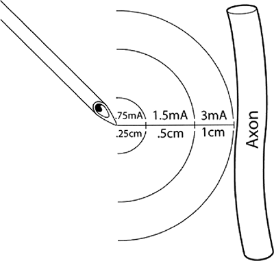
characteristic rheobase of a nerve (Fig. 4-1)
is the lowest current amplitude with long or indefinite pulse duration
applied to depolarize a nerve. Chronaxie is the pulse duration at which
the threshold current amplitude is twice that of the rheobase. A pulse
duration longer than the chronaxie is not desired because current
consumption is increased without decreasing the threshold significantly.
chronaxie, and t = pulse duration, illustrates that the current
amplitude necessary for nerve stimulation is very dependent on the
pulse duration of the stimulus. Larger fibers are more easily
stimulated than smaller fibers. Large motor fibers can be stimulated
with pulse durations as low as 0.05 ms with very little discomfort.
 |
|
Figure 4-1.
Approximate distances between needle microelectrode and the targeted axon in practice when a pulse duration of 0.1 ms is utilized. Actual distance and current amplitude varies to some degree depending on actual electrical impedances of the tissues between the stimulating electrode and the nerve. Such variations are minimized by use of a constant current generator. (Reprinted with permission from Bollini C, Cacheiro F. Peripheral nerve stimulation. Tech Reg Anesth Pain Manage 2006;10:79–88.) |
previously described surface anatomical landmarks. Such landmarks have
been widely published and underlie the various techniques used for
regional anesthetic blocks. Surface landmarks have been described for
many different peripheral nerves or plexuses of nerves. Following
identification of landmarks, a block needle has been used to search for
a distinct endpoint with the objective of putting the needle tip in the
immediate vicinity of the targeted nerve or nerves. Two categories of
endpoints exist in practice. Anatomical endpoints
are dependent on intimate anatomical relationships of other structures
to the targeted nerve or nerves. Examples of regional anesthetic
techniques that utilize anatomical endpoints include transarterial or
periarterial techniques for brachial plexus block, field blocks, or the
use of imaging techniques such as ultrasonographic guidance. Functional endpoints,
by contrast, require neural function; that is, a neural response to
mechanical or electrical stimulation. The two major functional
endpoints that have been used in clinical practice include: 1) a
sensory response to mechanical stimulation (i.e., a mechanical
paresthesia), and 2) a motor response to electrical stimulation (i.e.,
a muscular twitch).
dominated the field of regional anesthesia in recent years. The major
difference between the use of a motor response to electrical
stimulation and a mechanical paresthesia is that the motor response is
a graded phenomenon that yields information about nerve location from a
distance, whereas a mechanical paresthesia is an all-or-nothing
response requiring contact with the nerve. A mechanical paresthesia
supplies no information at distance from the nerve.
rectangular wave current generator. By altering the time base on an
oscilloscope, these waves can be graphed as “square-waves”; therefore,
nerve stimulators are referred to as square-wave generators.
These square waves or “pulses” are programmed to occur at a given
frequency, typically 1 to 2 Hz (1 to 2 cycles/sec). Most commercially
available nerve stimulators today are constant current generators that
deliver accurate pulses of electrical current in the face of varying
tissue impedances (resistances, capacitances, and inductances). The
newest commercially available peripheral nerve stimulators are capable
of producing electrical pulses of accurate duration in the 0.1 to 1.0
ms range. They have the capability of continuously and accurately
controlling electrical current amplitude in the range of 0 to 5 mA.
Armed with modern peripheral nerve stimulators, the regional anesthesia
practitioner is able to control the following variables during nerve
location: 1) electrical pulse frequency, 2) current amplitude
(amperage), 3) electrode conductive area, 4) electrical pulse duration,
and 5) tissue electrical impedance.
during peripheral nerve stimulation is 2 Hz. This frequency is the same
as that used during train-of-four stimulation used to monitor the
degree of motor blockade during general anesthesia. Although most
stimulators allow 1 Hz stimulation, 2 Hz stimulation results in more
rapid feedback, thus serving to decrease the amount of time required
for nerve location. Frequency can be increased above 2 Hz, but above 4
Hz there is inadequate time for the relaxation phase of the action
potential, which results in sustained tetanus. Therefore, 1, 2, or 3 Hz
are acceptable frequencies during neural location.
a homogeneous medium of constant impedance follows what is commonly
referred to as the “inverse square law.” The
relationship
between required electrical current was first understood and described
by Coulomb in the 1780s. The relationship between the required
electrical current to stimulate a nerve and the distance to the nerve
follows Coulomb’s law:
 |
|
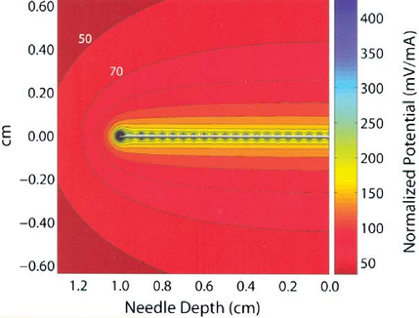
Figure 4-2.
As shown in this computer model of an electrical field surrounding a block needle used in nerve location, electrical current dissipates very quickly from the tip of the needle to the inverse square of the distance from the needle tip. Movement of the needle tip just a few millimeters away from the nerve may require several-fold current increases to achieve similar motor response to electrical stimulation. (Reprinted with permission from Johnson CR, Barr RC, Klein SM. A computer model of electrical stimulation of peripheral nerves in regional anesthesia. Anesthesiology 2007;106:323–330.) |
= minimal required stimulation current, and r = distance between
electrode and nerve. According to this law, or as can be seen from this
relationship as described by Coulomb’s law, electrical current
dissipates very rapidly as a function of the distance from the tip of
the stimulating electrode (to the inverse square of the distance
between the needle and the nerve). This relationship was recently
analyzed by computer modeling by Johnson, et al. and is illustrated in Figure 4-2.
As a stimulating electrode moves away from a peripheral nerve, the
amount of current necessary to stimulate the nerve increases
significantly. The converse is the underlying principle of nerve
location utilizing electrical stimulation; that is, the ability to
elicit a motor response at very low amperage (e.g., ≤0.5 mA) and low
pulse duration (e.g., 0.1 ms) indicates extremely close proximity of
the needle tip electrode to the nerve. Sung showed in studies of rabbit
sciatic nerve that such stimulation correlated with a distance of
approximately -1 mm to +1 mm in relation to the targeted sciatic nerve.
This principle is responsible for the very high success rates published
in clinical studies of peripheral nerve stimulation. Higher current
amplitude (e.g., 0.5 to 5 mA) allows for stimulation and therefore
visual cues at greater distance from the nerve or through the skin.
Therefore, higher current amplitudes can be used for transcutaneous
stimulation and nerve mapping at a distance from the targeted nerve or
neural plexuses.
inversely related to an electrode’s conductive area. This relationship
is described by Ohm’s law:
distance to the nerve, and A = conductive area. Therefore, when the
goal is to minimize resistance to electrical current, as is the case
with ventricular defibrillation by external chest paddles, the
electrode surface is designed to be very large. For
electrocardiographic recordings, electrodes are typically approximately
1 cm in diameter to minimize resistance. By contrast, needle-tip
microelectrodes are used during nerve location for peripheral nerve
block in order to limit electrical dispersion to a small microsphere at
the needle tip. This ensures that the needle tip must be very close to
the nerve to result in stimulation and motor response, thereby
enhancing specificity and accuracy of nerve location. This property has
lead to shielding of stimulating needles used in regional anesthesia.
Bashein studied the difference between shielded microelectrode needles
and metal needles that were not electrically shielded by the use of
electrophoresis. These investigators found that the current dispersion
was limited to the tip of the electrically shielded needle, but the
unshielded needles conducted along the shaft as well as the tip.
wave pulse generated by a nerve stimulator at a given frequency. Short
pulse durations of 0.05 to 1 ms have been used clinically for nerve
location during regional anesthetic techniques. The 0.1 ms duration is
the most commonly used clinically for ultimate nerve location prior to
injection of local anesthetic. The total electrical charge of an
electrical pulse is the product of the current amplitude (amperage) and
pulse duration. Increasing electrical pulse duration increases the
charge by allowing a greater flow of electrons to occur during the
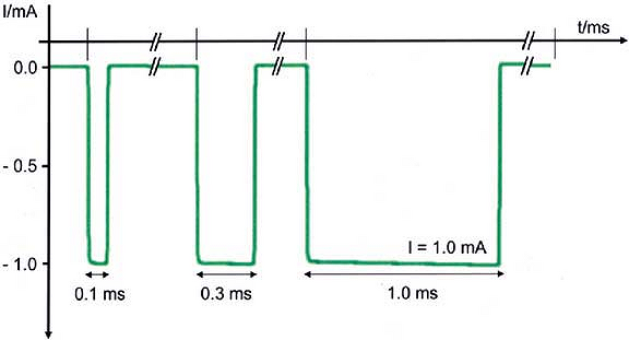
pulse. The total electrical energy is proportional to the calculated
area under the curve of the rectangular pulse wave (Fig. 4-3).
Therefore, simply by increasing pulse duration there is an increased
ability to stimulate the nerve at any given amperage if all other
parameters remain the same. Hadzic et al. showed that higher current
amplitude was needed to elicit a similar motor
response
at lower pulse duration in a study of volunteers. Increasing electrical
pulse duration also increases the ability to stimulate the nerve at a
distance similar to what occurs when increasing amperage. Therefore, an
increase in pulse duration results in an increase in sensitivity or
ability to elicit a motor response during electrical nerve stimulation.
Conversely, use of a higher pulse duration is less specific for final
nerve location; that is, the ability to stimulate at ≤ 0.5 mA using
pulse durations of, for example, 0.3 ms or 0.5 ms, at the same amperage
would not be expected to yield the same high success rates that have
been found at ≤ 0.5 mA, using a 0.1 ms pulse duration.
 |
|
Figure 4-3.
Actual oscilloscopic tracings of three square-wave pulses of 1 mA current amplitude from a commercially available peripheral nerve stimulator (B. Braun HNS 11). Current is shown in negative milliamperes (mA, y-axis) versus time base in milliseconds (ms, x-axis). Increasing pulse duration to 0.3 ms or 1.0 ms progressively increases the calculated area under the curve representing a larger flow of electrons for the same current amplitude. Larger pulse durations result in an increased ability to stimulate the nerve at a distance or through the skin without patient discomfort. (Adapted with permission from Urmey W, Grossi P. Use of sequential electrical nerve stimuli [SENS] for location of the sciatic nerve and lumbar plexus. Reg Anesth Pain Med 2006;31:463–469.) |
inverse of tissue conductance. Flow of electrical current is inhibited
by tissues of higher impedance. The electrical impedance of a tissue is
a function of the tissue’s resistance, capacitance, and inductance.
However, impedance mainly represents electrical resistance in
biological tissues. In general, the higher the lipid/water ratio, the
higher the tissue resistance or impedance. Tissues have varying degrees
of electrical impedance. Impedance varies, in general, according to
tissue type as indicated below:
the course of peripheral nerves or elongated nerve plexuses.
Transcutaneous stimulation has been described to map nerves in children
and adults. Prelocation of nerves or nerve plexuses gives information
noninvasively to aid in nerve location. In theory, nerve mapping serves
to decrease the number of invasive needle passes when searching for
nerves.
tissues with the exception of underlying bone or lung. Conventional
surface landmarks are useful starting points for mapping the course of
the neural plexus or peripheral nerve. Since nerves are composed of
specialized conductive tissue, they are characterized by very low
electrical resistance. Other tissues have varying electrical
resistances. By indentation of these other tissues toward the nerve,
resistance is diminished and nerves can be mapped more easily and at
lower current amplitudes. Use of smaller (i.e., ≤1 mm) diameter
stimulating electrodes results in increased accuracy in outlining the
course of the nerve or neural plexus.
course from the entry point for the conventional interscalene block by
the Winnie technique to the needle entry point for the conventional
axillary block. This course has been discussed in publications by
Grossi, who coined the term the “Anesthetic Line” to describe it.
Transcutaneous stimulation of the brachial plexus with a peripheral
nerve stimulator can be easily achieved anywhere above the clavicle at
low amperage by indentation of the overlying skin and subcutaneous
tissues (Fig. 4-4).
The brachial plexus courses below the clavicle, the infraclavicular
area where needle entry points for conventional infraclavicular or
coracoid approaches occur, posing more of a problem for successful
transcutaneous stimulation. In thin adults, transcutaneous stimulation
can be achieved with indentation of the overlying skin, subcutaneous
tissues, and muscle. Since the plexus is deeper at this point, it is
not always possible to stimulate transcutaneously at low milliamperage
in larger adults. It is easier to successfully stimulate the brachial
plexus at the point described for needle entry for vertical
infraclavicular block (VIB) than for infraclavicular block sites that
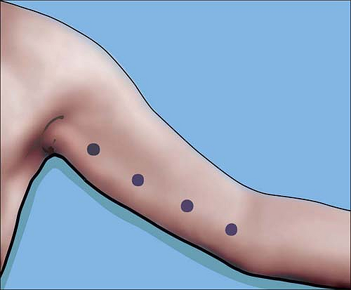
are more lateral. Moving to the axilla, axillary transcutaneous mapping
of the brachial plexus can be easily and separately done
for each of the four terminal nerves of the brachial plexus—median, radial, ulnar, and musculocutaenous.
 |
|
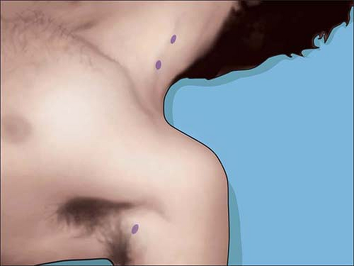
Figure 4-4.
Typical transcutaneous stimulation points at <5 mA outline the “anesthetic line of Grossi.” Nerve mapping all along the brachial plexus can be performed except over bony prominences. |
anywhere from the axilla to the elbow for the median nerve which
crosses the brachial artery at approximately the midhumeral level. The
artery can serve as a landmark. The ulnar nerve can be similarly mapped
very easily from axilla to elbow (Fig. 4-5).
The radial nerve by contrast is easily mapped by transcutaneous
stimulation at the axilla by indentation of the skin from above or
below the artery toward the posterior aspect of the axillary artery. As
the nerve courses more distally, it moves deeper and more posteriorly.
Nevertheless, it can be mapped by indentation of the skin under the
biceps toward the posterior aspect of the arm. The musculocutaneous
nerve results in biceps contraction. It is best mapped only at the
axilla, at the origin of the biceps. The musculocutaneous nerve cannot
be reliably mapped in the midhumeral region since direct stimulation of
the biceps muscle cannot be distinguished from stimulation of the
nerve, itself. At the wrist, the median and ulnar nerves can each be
stimulated transcutaneously.
stimulated transcutaneously by indentation of the skin and underlying
tissues at the level of the femoral crease. The femoral nerve is very
superficial at this point, even in large or obese adults. Because of
the large complement of motor nerve fascicles to the quadriceps,
achievement of a motor response is very easy. The fibers to the
adductors are superficial and/or medial to the fibers enervating the
vastus muscles of the quadriceps. Therefore in practice, if motor
response to the adductor is all that can be achieved, the quadriceps
motor response will be achieved by going through these fibers with the
needle. This occurs in approximately 50% of adults. Thus, the ability
to stimulate only the adductors can be classified as successful nerve
mapping of the femoral nerve.
thigh where the conventional Labatt approach occurs. At this point,
transcutaneous stimulation is not normally
possible
in the adult. By contrast, stimulation can occur in thin adults at the
popliteal block point, approximately 7 cm above the popliteal crease.
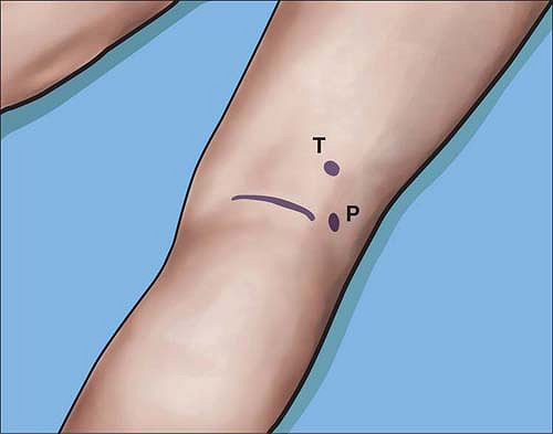
Alternatively, the components of the distal sciatic nerve, the common
tibial, and common peroneal nerve can each be stimulated separately and
easily a few centimeters above the popliteal crease (Fig. 4-6).
 |
|
Figure 4-5.
Course of the ulnar nerve from axilla to elbow can be determined by transcutaneous stimulation at approximately 2 mA. In contrast to the median nerve, the ulnar nerve should not be blocked at the elbow near or at the ulnar groove. |
posterior tibial nerve can be easily stimulated transcutaneously just
behind the medial malleolus to assist with ankle block. Stimulation at
this point causes plantar flexion of the foot by means of the intrinsic
musculature of the foot. This is a slightly different, less intense
motor response than results from stimulation of the tibial nerve or
sciatic nerve more proximally, where a motor response includes
extrinsic as well as the intrinsic muscles.
block needle refers to transcutaneous stimulation followed by physical
guidance of the needle tip toward the nerve by the transcutaneous
electrode itself. This was first described by Urmey and Grossi in 2002.
In their original report, they described the use of a cylindrical
electrode with a 1 mm conductive tip. This was used to stimulate the
nerve transcutaneously, following which a separate needle electrode was
guided toward the nerve. This technique was later modified by the
investigators. The newer technique utilized the stimulator needle
electrode tip itself for transcutaneous stimulation. The needle
electrode was protected by being encased in smooth rounded plastic.
This allowed for indentation percutaneous electrode guidance of the
needle
tip
by use of a single electrode and nerve stimulator to achieve
transcutaneous as well as invasive nerve stimulation. This technique
can be used on any of the nerves or plexuses that can be mapped as
described above. Following the initial reports, Capdevila et al. used
the needle electrode itself, without indentation of the skin, to
successfully transcutaneously and subsequently invasively stimulate the
underlying nerves of the axillary brachial plexus. In comparison with
the above techniques of indentation percutaneous electrode guidance,
use of the needle alone is limited to very superficial nerves and
requires much higher current amplitude than when skin and underlying
tissues are indented toward the nerve.
 |
|
Figure 4-6. The common tibial (T) or common peroneal (P) nerves can be stimulated close to the popliteal crease at <0.5 mA.
|
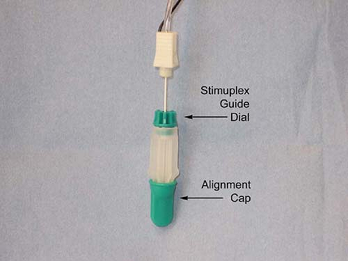
guidance is done by first loading a standard 22-gauge 50- to 100-mm
insulated block needle into a Stimuplex Guide (Fig. 4-7),
by dropping the needle vertically into the Stimuplex Guide. The needle
tip is aligned by means of a removable alignment cap. An adjustable
dial is then turned to secure the needle and maintain the alignment
when the alignment cap is removed. This in effect converts the sharp
block needle into a smooth transcutaneous microelectrode that can be
used to indent the skin for prelocation of the nerve or plexus without
scratching or injuring the skin or overlying tissues. The point at
which stimulation can occur transcutaneously at lowest amperage
utilizing a 1 ms pulse duration is determined, following which the
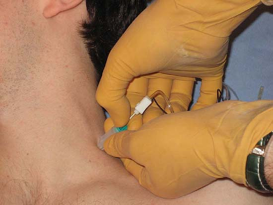
amperage is lowered to 1 mA and pulse duration to 0.1 ms. The Stimuplex
Guide dial is then turned to release the needle thus allowing the
needle to be freely advanced toward the targeted nerve (Fig. 4-8). The remainder of the technique is the same as with conventional invasive nerve stimulation techniques.
 |
|
Figure 4-7.
Photograph of Stimuplex Guide used for indentation percutaneous electrode guidance (PEG) with alignment cap in place. Adjustable dial at needle shaft is indicated. Adjustable dial is tightened by turning in a clockwise direction as viewed from above to secure needle within Stimuplex Guide. (Reproduced with permission from Jankovic D. Regional Nerve Blocks and Infiltration Therapy: Textbook and Color Atlas. 3rd Edition. Germany: Wiley-Blackwell, 2004.) |
 |
|
Figure 4-8.
Stimuplex Guide used for indentation percutaneous electrode guidance (PEG). Here, skin is indented toward the plexus, the adjustable dial is released, allowing the needle to be inserted to the neural plexus. (Reproduced with permission from Jankovic D. Regional Nerve Blocks and Infiltration Therapy: Textbook and Color Atlas. 3rd Edition. Germany: Wiley-Blackwell, 2004.) |
on a scientific understanding of several variables that can be
manipulated to achieve both sensitivity and specificity during the
search for the targeted nerve. Use of accurate constant current
generators and electrically insulated microelectrode needles achieves
the required high specificity for ultimate nerve location. Variables
utilized during peripheral nerve stimulation techniques include current
amplitude, pulse duration, microelectrode size, and the distance
between the electrode and the targeted nerve. Nerve mapping and
prelocation of the course of a neural plexus or peripheral nerve can be
used to assist or facilitate subsequent invasive needle exploration.
Greater sensitivity is achieved for nerve mapping and prelocation by
increasing current amplitude and pulse duration, as well as by
indenting the overlying skin and subcutaneous tissues toward the
targeted nerve, which serves to decrease the distance to the nerve as
well as the impedance or resistance of the overlying tissues.
Indentation percutaneous electrode guidance serves to combine nerve
mapping or prelocation with ultimate invasive nerve location.
G, Haschke RH, Ready LB. Electrical nerve location: numerical and
electrophoretic comparison of insulated vs uninsulated needles. Anesth Analg 1984;63:919–924.
X, Lopez S, Bernard N, et al. Percutaneous electrode guidance using the
insulated needle for prelocation of peripheral nerves during axillary
plexus blocks. Reg Anesth Pain Med 2004;29:206–211.
A, Vloka J, Hadzic N, et al. Nerve stimulators used for peripheral
nerve blocks vary in their electrical characteristics. Anesthesiology 2003;98:969–974.
A, Vloka JD, Claudio RE, et al. Electrical nerve localization: effects
of cutaneous electrode placement and duration of the stimulus on motor
response. Anesthesiology 2004;100:1526–1530.
C, Prithvi P, Ford D. The use of peripheral nerve stimulators for
regional anesthesia. A review of experimental characteristics,
technique and clinical applications. Reg Anesth 1985;10:49–58.
HC, Gielen MJ, Boersma E, Klein J, Groen GJ. Vertical infraclavicular
block of the brachial plexus: effects on hemidiaphragmatic movement and
ventilatory function. Reg Anesth Pain Med 2005;30:529–535.
W, Grossi P. Percutaneous electrode guidance (PEG) and subcutaneous
stimulating electrode guidance (SSEG): modifications of the original
technique. Letter to the Editor. Reg Anesth Pain Med 2003;28:253–255.
W, Grossi P. Percutaneous electrode guidance (PEG): a noninvasive
technique for pre-location of peripheral nerves to facilitate nerve
block. Regional Anesthesia and Pain Med 2002;27:261–267.
Helmhotz H. Messungen uber den zeitlichen verlaug der Zuchung
animalischer Muskern und die Fortphanzungsgeschwindigkeit der Reizung
in den Nerven. Arch Anat Phisiol 1850:277.