
Cole & Sekiya: Surgical Techniques of the Shoulder, Elbow and Knee in Sports Medicine, 1st ed.
Copyright ©
2008 Saunders, An Imprint of Elsevier
CHAPTER 59 – Distal Femoral Osteotomy
Declan J. Bowler, MD, FRCSI (Tr & Orth)
Malalignment affects the articular surfaces of the knee more than any joint of the lower extremity. Deformity of the distal femur can arise as a genetically determined morphologic characteristic; from congenital disorders; from metabolic disorders, such as rickets; from developmental causes, such as asymmetric growth arrest; or as a result of traumatic or infectious sequelae. With so broad a range of etiologic factors, no two deformities are alike, and a “cookbook” approach to distal femoral osteotomy should be avoided. Further, it is not uncommon for vectors causing deformity in the distal femur to affect other metaphyseal and diaphyseal segments of the lower extremity. For this reason, the surgeon should be keenly aware of the mechanical alignment and joint orientations of the entire limb and not just those of the knee.
outlines our approach to planning and performing distal femoral osteotomies.
Preoperative Considerations: Define the Deformity
The history should elicit an approximate, if not specific, time of onset of symptoms and when the deformity was first noted. A cause, if possible, is determined. The location, character, and exacerbating and relieving aspects of pain are documented. It is not uncommon for the patient with lateral gonarthrosis, the most common indication for distal femoral osteotomy, to present with pain symptoms lagging far behind those expected from the radiographic appearance of the joint. Crepitation, a sign of chronic synovial inflammation, may be a more constant sign of the chronic arthritic changes.
The presence of clicks, pops, catching, and locking may suggest internal derangement, such as meniscal tears, chondral lesions, or synovial plicae, that should be addressed, usually arthroscopically, at the time of the osteotomy.
During the physical examination, visual inspection of the standing patient should be carried out from the coronal and sagittal perspectives. If the pelvis is not level, leveling blocks are placed under the short limb until a level pelvis is achieved, and the height of those blocks is noted. The examination should include a Trendelenburg test, and the gait pattern should be characterized (e.g., Duchenne, antalgic, selective motor weakness). With the patient supine, leg length and tibiofemoral angles are measured. Clinical measures for rotational deformity (femoral anteversion, thigh-foot angle, transmalleolar axis) are recorded. A comprehensive examination is conducted of the hip, knee, ankle, and hindfoot-midfoot joints, looking critically for instability, internal derangement, and arthritis. If ligament instability is diagnosed, stress radiographs as well as standard views should be ordered.
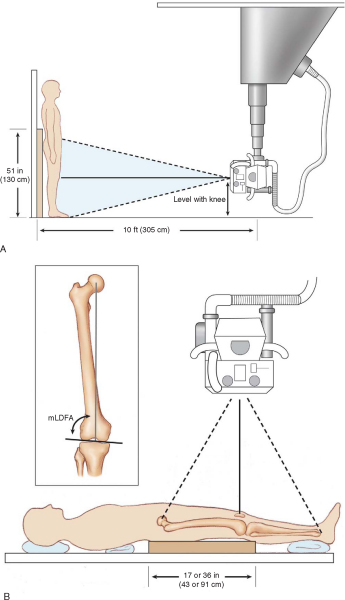
Proper imaging protocols are necessary to facilitate preoperative planning. The most critical view is a coronal plane anteroposterior film showing the entire limb. This view is typically obtained with the patient standing and with blocks under the foot of a short side (if such exists) to level the pelvis. A 51-inch cassette or newer digital stitching technique is used to capture the image. The flexion axis of the knee should be oriented to lie in the plane of the film to allow accurate determination of the mechanical and anatomic axes and coronal plane joint orientation angles (
Fig. 59-1
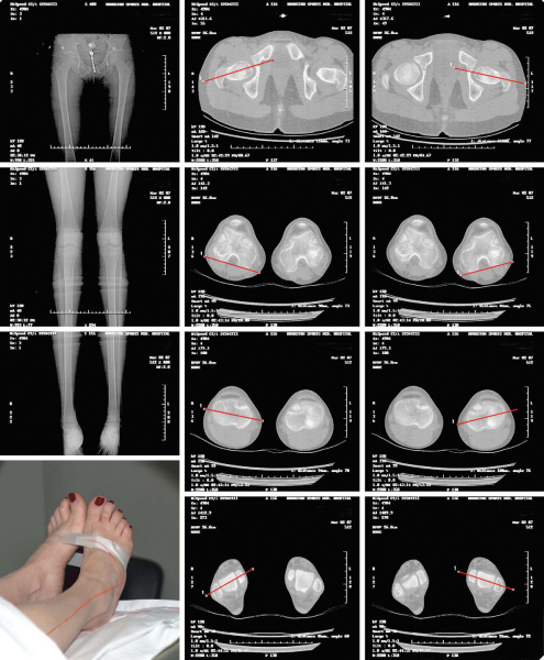
). Supine anteroposterior and lateral images with the beam centered at the knee are obtained for specific osteotomy planning. A lateral film in extension encompassing at least the distal half of the femur and proximal half of the tibia is needed to determine if any sagittal planar deformity exists, which could indicate the need for biplane osteotomy techniques. If deformity or incongruity of the articular surface is suspected, it is best evaluated by computed tomographic coronal and sagittal plane reconstructions. Axial malalignment may be more precisely quantified with computed tomographic alignment studies (
Fig. 59-2
). If the clinical examination suggests ligament and meniscal disorders, they can be further characterized by magnetic resonance imaging.
|
|
|
|
Figure 59-1 |
|
|
|
|
Figure 59-2 |
Indications and Contraindications
A significant mechanical axis deviation, if left untreated, causes unicompartmental overload, meniscal damage, and arthritic deterioration. [7] [14] Distal femoral osteotomy is indicated when a mechanical axis deviation is present and the deformity is determined to exist in the distal femur. If the deformity is elsewhere, a distal femoral osteotomy can cause malalignment of normal joint orientation. Distal femoral osteotomy can also be done as an adjunct to knee ligament surgery when medial ligament instability and valgus of the limb deformity coexist or if lateral ligament instability and varus deformity of the limb coexist. Again, the axis of the limb deformity must be in the distal femur. There is a relative contraindication for patients who are smokers or have vascular insufficiency, contracture at the knee, or advanced arthrosis.
Preoperative Planning: Determine the Location for the Osteotomy
The completion of an analytical and in-depth preoperative plan is as essential to a successful outcome as the surgical technique. Paley[12] and coworkers have developed a rational and comprehensive method for deformity correction planning, which consists of a malalignment test, joint orientation measurement, joint line congruence assessment, and determination of the proposed level of correction.
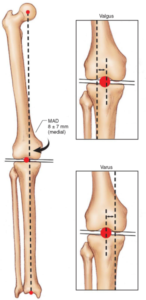
The malalignment test involves determination of mechanical axis deviation on a full-limb coronal plane image.
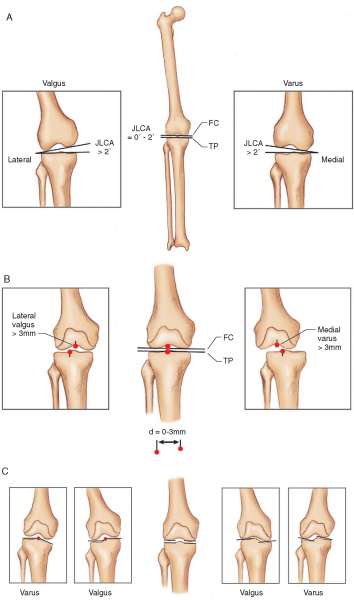
| Step 1: | A line is extended from the center of the femoral head to the center of the tibial plafond. This line should fall on the tibial spine. If it falls medial to the tibial spine, varus malalignment exists; and if it falls lateral to the tibial spine, valgus malalignment exists ( Fig. 59-3 ). If no mechanical axis deviation can be demonstrated, the benefit of osteotomy should be questioned. |
|
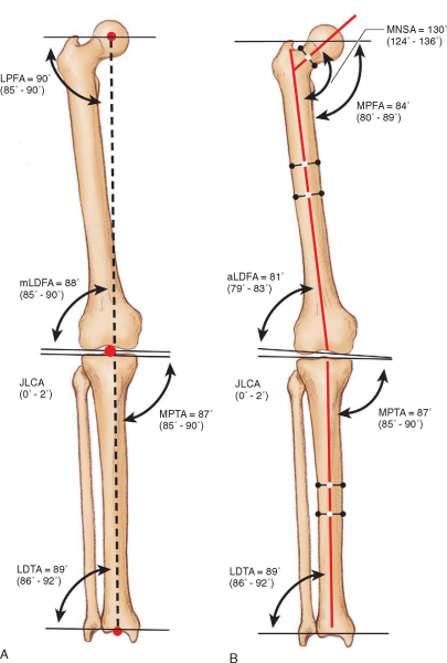
| Step 2: | The mechanical lateral distal femoral angle (mLDFA) or anatomic lateral distal femoral angle (aLDFA) is measured ( Fig. 59-4 ). If it is found to be outside the range of normal, the deformity contributing to malalignment at least partly exists at the level of the distal femur. For a distal femoral osteotomy to be indicated, there should be an abnormal mLDFA or aLDFA. |
|
| Step 3: | The medial proximal tibial angle is measured (see Fig. 59-4 ). If it is found to be outside the range of normal, the deformity contributing to malalignment at least partly exists at the level of the proximal tibia. |
|
| Step 4: | The joint line congruence angle is measured. If it is greater than 2 degrees, some component of the malalignment is due to loss of joint cartilage, ligament laxity, or condylar malalignment, which should be determined and factored into the ultimate correction ( Fig. 59-5 ). |
|
|
|
|
Figure 59-3 |
|
|
|
|
Figure 59-4 |
|
|
|
|
Figure 59-5 |
It is also important to determine what malorientation, if any, exists at the hip and ankle. Malorientation of the hip may require a second, more proximal osteotomy or an adjustment of the osteotomy level on the femur to restore a normal mechanical axis (even if it results in a slightly nonanatomic diaphysis). More important, if a distal femoral osteotomy of any significant degree is performed, the degree to which it will change the plane of the ankle to the plane of the floor must be considered. If an oblique ankle joint plane is created as a result of a distal femoral (or proximal tibial) osteotomy, a second normalizing osteotomy to correct the ankle must be planned as well (
Fig. 59-6
).
|
|
|
|
Figure 59-6 |
Joint line congruence can affect mechanical axis deviation in several ways (see
Fig. 59-5
). Ligamentous laxity may not be apparent in a standing or static film, making a ligamentous examination of the knee an essential component of the initial evaluation. If it is suggested from the examination, stress radiographs should also be obtained. If the midpoints of the femoral and tibial condyles diverge by more than 3 mm, subluxation exists and is therefore at least a component of the mechanical axis deviation. Finally, condylar incongruity can be detected by extending lines across the medial and lateral hemicondyles (tibial and femoral). These lines should be collinear, and if they are not, the varus and valgus deformity and mechanical axis deviation result at least in part from the articular surface deformity.
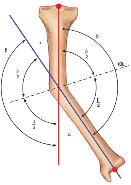
An understanding of the terms angular correction axis, center of rotation of angulation, and transverse bisector line is important when the surgeon is planning an osteotomy. When an angular correction is performed, an axis line in space, that is, a hinge, is defined on which one bone segment rotates relative to the other. This axis is referred to as the angular correction axis. Any angular deformity of bone can be thought of as having one bone axis proximal to the deformity and another distal to the deformity. The point of intersection of the proximal and distal axes is the center of rotation of angulation. Finally, a line drawn through the center of rotation of angulation that bisects the medial and lateral angles subtended by the proximal and distal axis line intersections is referred to as the transverse bisector line (
Fig. 59-7
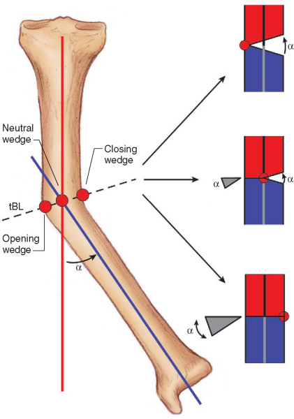
). The significance of the transverse bisector line is that if the angular correction axis is located anywhere along it, there will be collinear realignment of the axis. If a closing wedge osteotomy is to be performed, the angular correction axis is placed on the transverse bisector line where it intersects the concave cortex. For an opening wedge osteotomy, the angular correction axis should be located on the transverse bisector line where it intersects the convex cortex (
Fig. 59-8
).
|
|
|
|
Figure 59-7 |
|
|
|
|
Figure 59-8 |
Paley[12] described three rules governing osteotomy planning:
| 1. | If the osteotomy and the angular correction axis pass through the center of rotation of angulation, collinear realignment of the axis of the bone segments occurs ( Fig. 59-8 ). |
|
| 2. | When the angular correction axis is placed at the center of rotation of angulation and the osteotomy site is placed at a level away from the center of rotation of angulation, the axis realigns; but both angulation and translation occur at the osteotomy site ( Fig. 59-9 ). |
|
| 3. | If the osteotomy and the angular correction axis are away from the center of rotation of angulation, a secondary translational deformity will occur ( Fig. 59-10 ). |
|
|
|
|
Figure 59-9 |

|
|
|
|
Figure 59-10 |

Ideally, the most straightforward osteotomy plan is to follow osteotomy rule 1; however, anatomic, fixation, or pathologic constraints may force the osteotomy to be positioned away from the center of rotation of angulation. The surgeon must realize that in this situation, if the angular correction axis (or hinge) is placed at the osteotomy and not at the center of rotation of angulation, a translational correction must be performed to correct the secondary translational deformity created. If this is not appreciated and not done, the mechanical axis deviation may not be corrected and joint overload may still exist even though the limb may appear realigned. One subtle example of this occurs in the case of joint incongruity and a mechanical axis deviation with no other metaphyseal or diaphyseal deformity. In such a patient, the deformity is based entirely on the joint surface deformity, and the center of rotation of angulation will be at the joint line. Any osteotomy other than a focal dome invokes osteotomy rule 3, resulting in a secondary translation deformity, which requires a translation correction to resolve the secondary translation.
To plan a coronal plane distal femoral osteotomy:
| • | Obtain a standing anteroposterior pelvis to foot radiograph with the beam centered on the knee as shown in Figure 59-1A . |
|
| • | Obtain supine anteroposterior and lateral films of the femur with the beam centered at the level of the knee as shown in Figure 59-1B . |
|
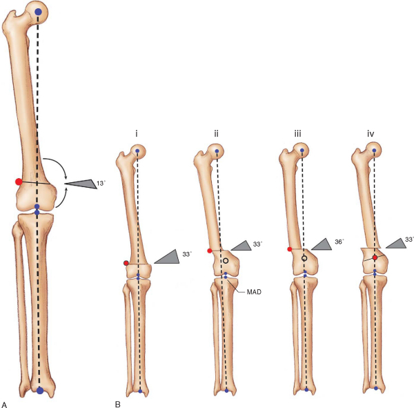
| • | Perform the malalignment test by extending a line from the center of the hip to the center of the ankle and determine mechanical axis deviation (Figs. 59-11 and 59-12 [11] [12]). | |
| • | Determine the mLDFA or aLDFA. It must be abnormal for a distal femoral osteotomy to be indicated (see Figs. 59-11 and 59-12 [11] [12]). | |
| • | Determine medial proximal tibial angle and other joint orientations. If they are also abnormal, multifocal osteotomies may be required (see Figs. 59-11 and 59-12 [11] [12]). | |
| • | Analyze the joint line congruence angle for ligamentous laxity, subluxation, and joint surface incongruency (see Fig. 59-8 ). |
|
| • | Plot the mechanical and anatomic axes of the femur (see Figs. 59-11 and 59-12 [11] [12]). | |
| • | Extend a normal mLDFA or aLDFA from the plane of the femoral condyles (see Figs. 59-11 and 59-12 [11] [12]). | |
| • | The intersection of these two lines determines the center of rotation of angulation (see Figs. 59-11 and 59-12 [11] [12]). | |
| • | From the location of the center of rotation of angulation and anatomic considerations, determine the level of osteotomy, type of osteotomy, angular correction axis, and whether a compensatory translation will be required. | |
| • | Note that before the preceding step, deformity in the sagittal plane, axial malrotation, and length discrepancy must also be determined and factored into the correction. |
|
|
|
|
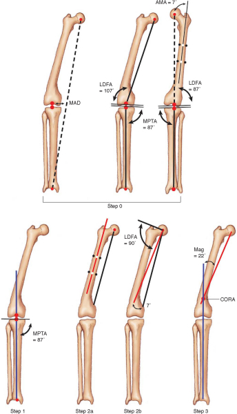
Figure 59-11 |
|
|
|
|
Figure 59-12 . Step 1: The anatomic axis of the femur is drawn and an anatomic lateral distal femoral angle (aLDFA) determined. Step 2: From the normal side, the aLDFA is determined and drawn. Step 3: The intersection of these two lines indicates the center of correction angulation and the subtended a angle indicates the magnitude of correction (Mag). (After Paley.[12]) |

In the foregoing description, we addressed only the most straightforward single-locus coronal plane deformity. However, the deformity can be sagittal as well as coronal; it can involve axial rotation, lengthening, or shortening; and it can occur at multiple loci on one bone or on both the femoral and tibial segments. The ultimate operative plan resolves all the vectors of deformity to restore normal limb mechanical alignment, joint orientation, and length.
Anesthesia, Room Setup, and Positioning
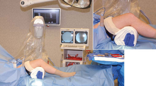
We perform osteotomies of the lower extremity with the patient under general anesthesia unless medical comorbidities preclude such. The patient is positioned supine on an orthopedic table with a completely radiolucent top (Jackson table; OSI, Union City, Calif). We typically use the same preparation and draping for the arthroscopic procedure (if one is performed) and the osteotomy procedure. The limb is draped free from hemipelvis distally; traction is not used. Useful positioning devices include a lateral post on the upper thigh, a roll of sterile bath towels approximately 1 foot in diameter secured with a sterile elastic adhesive wrap bolster under the knee during surgical approaches, and a sandbag or gel cushion secured to the table with tape so the heel can rest on it to help maintain a desired degree of knee flexion (
Fig. 59-13
). The surgeon stands on the same side for lateral and anterior approaches and on the contralateral side for medial approaches. A C-arm image intensifier is positioned on the opposite side of the surgeon.
|
|
|
|
Figure 59-13 |
Perform or Stage Intraarticular Procedures
Some forms of correction, such as those that involve the use of ring external fixators, may preclude the ability to move the limb through an adequate range of motion to prevent adhesions or the ability to treat the patient with continuous passive motion. In such cases, the intraarticular reconstructions may be done before the osteotomy or at a later date. The latter has greater appeal if intraarticular adhesions have formed; the arthroscopy can be an adjunct to their removal.
Surgical Exposure: Select an Approach
The knee is flexed to 90 degrees and the hip to 45 degrees for exposure and closure to normalize anatomic relationships and to maintain an even skin tension. If a tourniquet is to be used, we use a sterile tourniquet and maintain its inflation only for the exposure. Closure for all approaches is in layers. A bulky dressing and elastic outer wrap minimize edema and effusion.
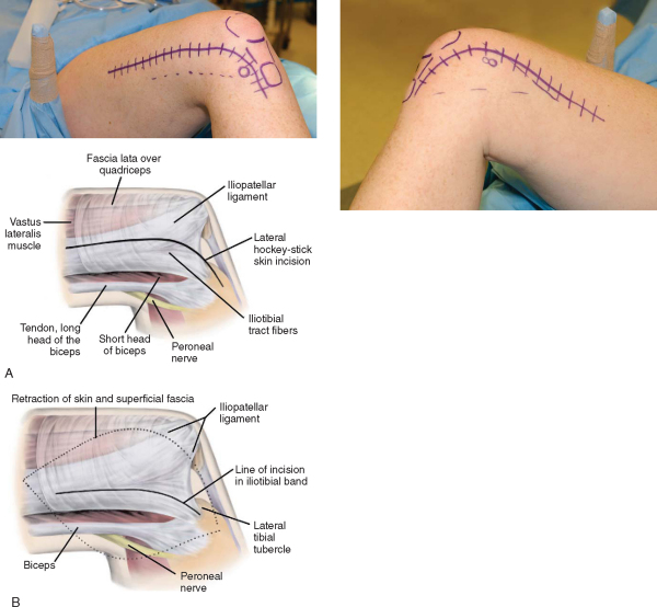
We use a lateral hockey-stick incision for lateral opening and closing wedge osteotomies (
Fig. 59-14
). The incision can be extended as far proximally as fixation demands. The skin incision is 2 cm anterior to the palpable posterior border of the iliotibial tract. Distally, this incision extends just dorsal and medial to the lateral tibial or Gerdy tubercle. The tract is split just anterior to the lateral intermuscular septum in the interval between the iliotibial tract and iliopatellar ligament fibers. The vastus lateralis muscle fibers of origin can be gently swept off the intermuscular septum with a sharp Cobb elevator. Some vascular perforators may be encountered as the dissection proceeds proximally; they must be cauterized or ligated. If dissection must extend distally to the condylar flare, the superolateral geniculate artery will be encountered and must be ligated. Subperiosteal dissection can then be carried out just at the osteotomy site, maintaining an intact periosteal sleeve.
|
|
|
|
Figure 59-14 |
We use a medial hockey stick incision for medial opening and closing wedge osteotomies (
Fig. 59-15
). The incision can be extended as needed with the caveat that Hunter canal and the femoral artery will be encountered above the distal third of the medial thigh; therefore, care must be exercised to prevent arterial direct or stretch injury. The skin incision is placed just anterior to the medial intermuscular septum and curves as it extends distally to course just medial to the patella and patellar tendon. The sartorial fascia is divided just on the anterior edge of the medial intermuscular septum. The origins of the vastus medialis oblique and vastus medialis muscles are elevated off the intermuscular septum. Again, vascular perforators, the superomedial geniculate artery (distally) and the femoral artery (proximally), may be encountered.
|
|
|
|
Figure 59-15 |

This approach is used primarily for a focal dome osteotomy. A full extensile approach, much like that used for total knee arthroplasty, is described here. However, the approach can be minimized by splitting it into a mini–medial arthrotomy (for insertion of a retrograde nail if retrograde nail fixation is used) and a minimal, or percutaneous, quadriceps tendon–splitting incision (for the osteotomy). The extensile skin incision closely parallels the medial border of the patellar tendon and patella, extending proximal to the knee in the anterior midline. The deeper arthrotomy incision divides the retinaculum on the medial border of the patella. The upper border of the fat pad may need to be incised. It is better to do so than to traumatize the fat pad, which can lead to fibrosis and secondary infrapatellar contracture. If a synovial plica is encountered, it can be spared or excised, but it should not be incised and repaired, which would lead to painful scarring. As the arthrotomy is extended proximally, it splits the quadriceps tendon along its medial border, leaving a thin cuff of tendon on the vastus medialis to facilitate closure. If the osteotomy is performed within the confines of the suprapatellar pouch, the synovial fatty layer over the periosteum should be incised sharply, protected, and repaired to minimize the possibility of adhesion of the quadriceps tendon to the femur.
Specific Steps (
Box 59-2
)
Bone cuts should be made with sharp blades or bits to minimize heat and thermal necrosis. Cutting technique can involve an oscillating saw cut, a Gigli saw cut (especially useful for metaphyseal percutaneous cuts), an osteotome corticotomy technique, and multiple drill holes (which can be a straight-line cut or involve use of guides such as focal dome guides).
| Surgical Steps | ||||||||||||
|
Closing wedge. With this classic corrective osteotomy type, a wedge corresponding to the angle of correction is removed in an attempt to maintain a small corticoperiosteal hinge at the angular correction axis. The bone is gradually deformed into closure by axial loading (
Fig. 59-16
). This osteotomy is usually stable and heals readily (6 to 10 weeks) when it is placed in metaphyseal bone. If the hinge fractures, it may be necessary to stabilize it as well. Once closed, an osteotomy in the metaphyseal segment will result in some degree of step-off, which increases with the magnitude of correction. Our general rule is to limit closing wedge osteotomies to a magnitude of correction resulting in a step-off no greater than 25% of the longer of the two osteotomy cuts. If a closing wedge is performed by other than osteotomy rule 1, a translation of the mechanical axis will occur unless the hinge is displaced.
|
|
|
|
Figure 59-16 |
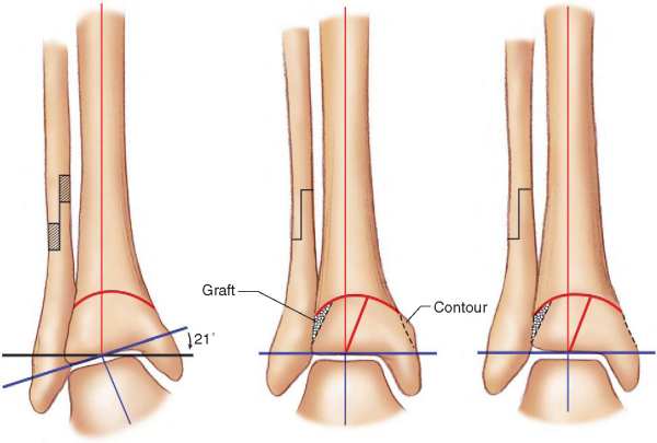
Opening wedge. The execution of this osteotomy is simpler because it requires only a single cut and no bone removal (
Fig. 59-17
). Again, preservation of a corticoperiosteal hinge at the angular correction axis is a goal, unless osteotomy rule 2 or rule 3 is being followed. The osteotomy is then angularly distracted by use of a variety of instruments, such as lamina spreaders, specialized osteotomy distractors, and temporary external fixators. Once it is open and stabilized, the defect is customarily grafted. We have had excellent success using a combination of a structural allograft (freeze-dried femoral head fashioned as a cortical wedge) with a center core filled with reamed autograft by the reamer-irrigator-aspirator system (Synthes USA, Paoli, Pa).
|
|
|
|
Figure 59-17 |

Biplane wedge. When an angular deformity occurs in both the coronal and sagittal planes, a variant of the closing and opening wedge osteotomies may be required. A biplane wedge can be cut (closing wedge type) or biplane distraction and fixation performed (opening wedge type) to achieve correction of the more complex deformity.
Focal dome. When the center of rotation of angulation exists at or extremely near the joint line, a focal dome osteotomy allows correction of the angular deformity without causing a secondary translation of the mechanical axis. For this type of osteotomy, a special focal dome guide is used (
Fig. 59-18
). Its axis of rotation is placed at the center of rotation of angulation, which will also become the angular correction axis. The osteotomy is usually performed with multiple drill holes and may even be accomplished through a minimal incision or percutaneous approach. The drill holes are connected with a narrow osteotome. The undulations of such a cut provide additional stability from derotation of the osteotomy once correction is achieved. They also act as gears for correction because the osteotome can be inserted into the osteotomy site and rotated, catching a drill hole edge and rotating the segment around the angular correction axis.
|
|
|
|
Figure 59-18 |
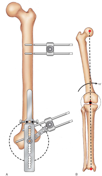
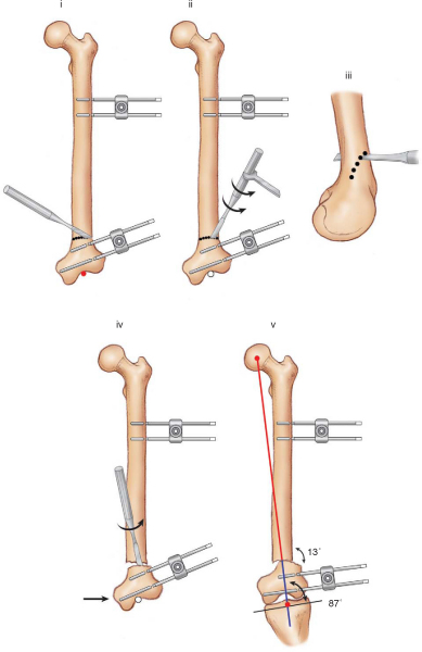
One method of focal dome correction, fixator-assisted nailing, involves the intraoperative application of a temporary monopolar external fixator to aid in achieving and holding a focal dome correction while a retrograde nail is passed (
Fig. 59-19
). This method ensures that the nail is channeled precisely through the distal segment to achieve the greatest stability. It also facilitates an almost percutaneous approach to performance and fixation of this osteotomy. The fixator is removed after the nail is locked.[12]
|
|
|
|
Figure 59-19 |
Callus distraction. Callus distraction, or Ilizarov-like procedures, are the method of choice for the following corrections: a severe magnitude; a deformity with a structure at risk, for example, a case in which an acute correction could result in neurovascular compromise; a significant translation; a leg length discrepancy as a component of the deformity; a severe rotational deformity; and a multiplane deformity that requires correction of angulation, translation, and rotation simultaneously. In these procedures, the frame is mounted to the limb segment, and a limited incision corticotomy is performed. For simpler angular corrections, the external fixator is applied so that the “hinge” of the fixator is placed on the angular correction axis or somewhere along the transverse bisector line. These more straightforward corrections can be accomplished with angulator-type monopolar fixators, such as the Heidelberg frame (Smith & Nephew, Memphis, Tenn). However, as the osteotomy nears the joint line, a ring with tensioned wires becomes necessary for adequate fixation of a short segment. The more complex deformities are best addressed with multiaxial frames, such as the Taylor Spatial Frame (Smith & Nephew, Memphis, Tenn), that allow correction of 6 degrees of freedom simultaneously. It is far beyond the scope of this chapter to discuss callus distraction techniques in detail, but many excellent resources exist for further training in these methods.
3. Perform and Assess Correction Intraoperatively
For single-stage osteotomies, correction is achieved by trying to maintain a corticoperiosteal hinge (for opening and closing wedge types) and intact periosteal sleeve. Closing wedge osteotomies are best corrected by gradual axial loading, deforming the hinge into closure. A variety of internal distractors or use of a temporary external fixator aids in achieving correction of opening wedge osteotomies. Focal dome osteotomies can be literally cranked into position by rotating a narrow osteotome inserted into the osteotomy site. Correction of the mechanical axis can be estimated intraoperatively by stretching a Bovie cord from the center of the femoral head to the center of the ankle (position verified by fluoroscopy and imaging of the knee to determine where the corrected mechanical axis falls;
Fig. 59-20
).
|
|
|
|
Figure 59-20 |

For callus distraction methods using external fixation and gradual correction, intraoperative assessment is obviously limited to ensuring that a complete corticotomy has been accomplished. The corticotomy is then compressed, and the external fixator position is locked.
A variety of fixation devices are available for stabilizing osteotomies of the distal femur.
Plate fixation. Probably the classic fixation of recent decades has been the fixed-angle blade plate. It affords excellent stability but is more technically demanding than other methods. The condylar screw plate offers the stability of a fixed-angle device but is technically easier to implant. This ease of insertion does, however, come at the expense of lesser rotational stability of the distal segment in the sagittal plane. Newer distal femoral locking plates function as a fixed-angle device with stability equivalent to a blade plate. They are less technically demanding than a blade plate or condylar screw plate, and many of these plates offer the ability to be implanted through a minimal incision. As the osteotomy level approaches the diaphyseal-metaphyseal junction, simple dynamic compression–like or locking plates may be adequate. A recent variant, the strut buttress plate, such as the Puddu plate (Arthrex, Naples, Fla), has been developed specifically for stabilizing opening wedge osteotomies (see
Fig. 59-17
).
Intramedullary rod. The retrograde rod and fixator-assisted nailing are discussed earlier in the section on focal dome osteotomy. Retrograde rods are capable of stable fixation of very distal osteotomies, although some morbidity to the knee joint is associated with their insertion. As the osteotomy level moves proximally, conventional antegrade nails can also be used. It is important to stabilize the correction provisionally, as with the fixator-assisted nailing technique, and to centralize reaming in the distal segment to prevent recurrence of the deformity. Blocking screws remain an option to aid in stabilizing antegrade rods in short distal metaphyseal segments.
External fixation. These techniques and options are discussed earlier in the section on callus distraction. They include monopolar, monopolar angulator, ring, and spatial frames.
PEARLS AND PITFALLS
|
It is critical to begin joint mobilization immediately, particularly if intraarticular procedures such as arthroscopy, synovectomy, and chondroplasty have been a part of the surgical technique. We begin passive joint mobilization and active-assisted joint range-of-motion exercises on postoperative day 1. If articular surface reconstruction was performed, we awaken the patient secured on continuous passive motion (CPM). CPM is continued 10 hours a day for 3 to 4 weeks, depending on the magnitude of the procedure. For non-CPM patients, an exercise bicycle with minimal resistance is initiated early. CPM patients transition off CPM to the bicycle. If joint rehabilitation as outlined cannot be undertaken as a result of the stability or constraints of fixation, for example, with the use of ring fixators, articular procedures are best done before, or preferably, after the osteotomy.
Isometric muscle rehabilitation is begun immediately. Closed chain resistive exercise is started as quickly as the limb allows. Functional rehabilitation begins when the osteotomy is sufficiently healed and motion and strength are within 20% of normal.
The surgery to weight-bearing interval is governed by a number of variables, including type of osteotomy, stability of fixation, bone quality, complexity of the correction, and whether the correction is being accomplished by single-stage osteotomy or callus distraction techniques.
With proper planning and patient selection, good technique, and appropriate rehabilitation, complications should be minimal. In our institution, the most common cause of reoperation after osteotomy has been for planned hardware removal. Incomplete planning, inadequate execution, and poor compliance of the patient can lead to a failure of a complete correction. This is also true with regard to a delayed union or nonunion that is affected by poor bone quality, poor circulation, and smoking during the healing or callus-distraction phase. Lack of adequate rehabilitation or failure to stage a procedure when appropriate may lead to persistent joint pain and stiffness. A failure to institute appropriate measures to identify risk and to provide adequate prophylaxis may lead to venous thrombosis. Nerve or vascular injury, although always a concern, is more of a risk in patients who require severe magnitude corrections. Unless it is preexisting, infection can be minimized with aseptic intraoperative and perioperative technique. If external fixation is used, pin track sepsis can be minimized with proper pin placement and a structured postoperative pin-site care program.
Results of Distal Femoral Osteotomy (
Table 59-1
)
Lateral Osteoarthritis and the Valgus Knee, Closing Wedge with a Blade Plate
Healy et al[5] reported their results in a series of 23 distal femoral osteotomies with a followup of 4 years. The Hospital for Special Surgery knee score improved from an average of 65 points to 86 points postoperatively in patients with osteoarthritis. McDermott et al[10] reported a successful result in 22 of 24 patients, for whom the greatest improvement was found in the pain category. Miniaci et al[11] reported 86% good or excellent results in a series of 40 patients, with a mean followup of 5.5 years. Finkelstein et al,[2] in a study of 21 knees, demonstrated that the probability of survival at 10 years was 64%. In an analysis of 15 closing wedge varus femoral osteotomies, Marti et al[9] obtained 75% good results without any complications. Marin Morales et al[8] reported on 17 cases of osteoarthritis of the knee with valgus deformity in 17 patients, treated by femoral supracondylar varus osteotomy. The mean followup time was 6.5 years. The Hospital for Special Surgery score was used to evaluate the clinical results, and nearly 75% were excellent or good. Wang and Hsu[16] described 30 patients with a mean duration of followup of 99 months; 25 patients (83%) had a satisfactory result and two had a fair result according to the Hospital for Special Surgery rating system. The remaining three patients had conversion to a total knee arthroplasty. With conversion to total knee arthroplasty as the endpoint, the cumulative 10-year survival rate for all patients was 87%, and the results did not appear to be affected by the presence of patellofemoral arthritis.
| Author | Mean Followup | No. of Procedures | Outcome |
|---|---|---|---|
| Lateral Osteoarthritis, Valgus Knee, Closing Wedge with Blade Plate | |||
| Healy et al[5] (1988) | 4 years | 23 in 21 patients | 83% (19/23) good or excellent, 17% (4/23) fair or poor; mean HSS knee score improved 21 points |
| McDermott et al[10] (1988) | 4 years | 24 patients | 22 successful |
| Miniaci et al[11] (1990) | 5.5 years | 40 patients | 86% good or excellent |
| Finkelstein et al[2] (1996) | 133 months | 21 in 20 patients | 64% 10-year survival rate |
| Marti et al[9] (2000) | Not reported | 15 | 75% good results |
| Marin Morales et al[8] (2000) | 6.5 years | 17 in 17 patients | 75% good or excellent HSS score |
| Wang and Hsu[16] (2005) | 99 months | 30 in 30 patients | 87% 10-year survival rate |
| Lateral Osteoarthritis, Valgus Knee with Other Fixation | |||
| Stahelin et al[15] (2000) | 5 years | 21 in 19 patients | 17 successful; 3 prolonged crutch use of immobilization; 1 failure |
| 18 loss of correction of 1.7 degrees | |||
| Lateral Osteoarthritis with Ligamentous Laxity | |||
| Cameron and Saha[1] (1994) | Not reported | 35 | 34 improved gait pattern |
| Paley et al[13] (1994) | 1 year | 23 in 17 patients | 19 excellent; 2 fair; 2 poor |
| Focal Dome Osteotomy | |||
| Gugenheim and Brinker[3] (2003) | 33 months | 14 | 12 had normal mechanical lateral femoral angle |
| Pediatric Torsional Deformity | |||
| Handelsman et al[4] (2005) | Not reported | 38 in 21 patients | Bone union occurred at an average of 10 weeks |
| HSS, Hospital for Special Surgery. | |||
Stahelin et al[15] used an incomplete oblique osteotomy of the distal aspect of the femur in 21 knees and stabilized the osteotomy site with a malleable semitubular plate, which was bent to form an angled plate, and lag screws. The mean duration of followup was 5 years. The osteosynthesis failed in only one knee. The loss of correction in 18 knees, after bone healing, averaged 1.7 degrees.
Koval et al[6] performed a biomechanical cadaver study in which a distal femoral osteotomy was created, reduced, and stabilized under compression by random assign-ment to one of three methods of fixation: (1) six-hole 95-degree supracondylar plate, (2) retrograde inserted statically locked supracondylar intramedullary nail, and (3) antegrade inserted statically locked nail. The 95-degree plate provided significantly stiffer fixation than the supracondylar intramedullary nail or antegrade nail in both a compressed transverse and a gap distal femoral osteotomy model. The 95-degree plate and antegrade nail had greater loads to failure than the supracondylar intramedullary nail.
Cameron and Saha[1] treated 35 patients with chronic medial collateral ligament instability with a distal femoral osteotomy. Improvement in gait pattern was achieved in 34 of 35 patients, but the medial collateral ligament usually remains lax even after the osteotomy. In another series, Paley et al[13] reported excellent results in 19 of 23 knees with medial collateral ligament laxity corrected by osteotomy and distraction osteogenesis, although most of the patients in the study had congenital or developmental dysplasia.
Gugenheim and Brinker[3] reported a series of patients with 14 femora with abnormal mechanical lateral distal femoral angles. They used an external fixator–assisted retrograde intramedullary nail and a percutaneous distal femoral dome osteotomy. The mean duration of followup was 33 months, and the mean healing time was 13 weeks. The mechanical lateral distal femoral angle was normal in 12 of the 14 knees.
Supracondylar osteotomies were performed on 38 femora in 21 children with femoral torsional and angular deformities.[4] All osteotomies were maintained by an external fixator. Bone union occurred at an average of 10 weeks.