
of biomechanics, and demonstrates how these concepts can be used to
understand the basic functions of bone fracture fixation devices and to
avoid clinical problems associated with the mechanics of fracture
fixation. Emphasis has been placed on addressing practical problems.
First, fundamental concepts of mechanics as they apply to the practice
of orthopaedic fracture fixation are explained. This is followed by a
short discussion on the mechanical organization of bone, its ability to
carry load, and the relationship of applied forces and specific
fracture patterns. A discussion of mechanisms of bone and joint injury,
including specific mechanisms observed in car crashes is next
presented. Description of the mechanics of healing bone follows, which
is relevant to understanding the timing of applying progressive load to
healing fractures in patients. Finally, the performance of various
types of fixation systems is discussed, with emphasis on fixation of
difficult fractures, such as the femoral neck and the tibial plateau,
and those involving osteoporotic bone. The focus of the discussion is
not on comparing the various specific devices available, but rather on
demonstrating the common mechanical principles involved in fracture
fixation so that potential problems common to various devices can be
recognized and avoided.
fixation, the fundamental mechanical question remains: is the fixation
system stiff and strong enough to allow the patient early mobility,
before bony union is complete, without delaying healing, creating bone
deformity, or damaging the implant, and yet flexible enough to allow
transmission of force to the healing fracture to stimulate union? The
issue of which brand of fixation is strongest or stiffest is not
specifically addressed because that is not the standard by which
different devices should be judged. Within a range of fixation
stiffness it has been shown that bone will heal, with the amount of
stabilizing callus compensating for more flexible fixation.
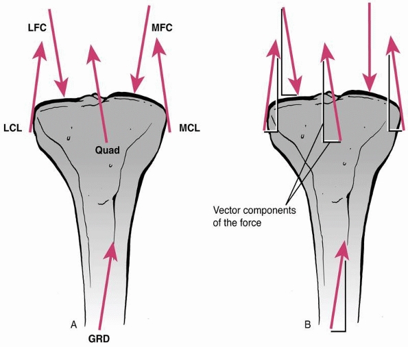
demonstrates, loads in many different directions may act on a fixed
fracture, including body weight, and forces induced by muscle
contraction and ligament tension. A force causes an object to either accelerate or decelerate. It has magnitude (strength) and acts in a specific direction, therefore it is termed a vector.
However complex the system of forces acting on a bone, each force may
be separated into its vector components (which form a 90-degree
triangle with the force). Any of several components, acting in the same
direction, can be summed to yield the net or resultant force.
As a simple example, consider the resultant force acting at the
shoe/floor interface during ambulation. It can be separated into a
vertical force because of
body
weight and a horizontal frictional force that produces the forward
thrust. Similarly, muscle forces can be separated in the same
manner—one force along the axis of the long bone and one perpendicular.
The components of the different forces that act in the same direction
can be added, and the resultant force acting on the bone can then be
found. This concept is important when designing fracture fixation
systems because it allows the designer to size the implants so that
they can withstand the mechanical loads applied without failure.
 |
|
FIGURE 1-1
Force vectors acting on a long bone during functional use as a result of muscle, tendon, and external forces. A vector indicates that the force has both magnitude and direction. The complex system of forces can be divided into components acting perpendicular and parallel to the ground, or the axis of the bone, then added to arrive at an overall resultant force. |
cause it to displace in a linear direction (translation) and those that
cause it to rotate around a joint center. Muscles typically cause a
bone to rotate (e.g., the biceps causes the forearm to rotate, the
anterior tibialis causes the foot to dorsiflex). When a force causes
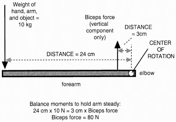
rotation, it is termed a moment and has a moment arm.
The moment arm is the lever arm against which the force acts to cause
rotation. It is the perpendicular distance of the muscle force from the
center of rotation of the joint. As shown in Figure 1-2,
the moment or rotary force is affected not only by the magnitude of the
force applied, but also by its distance from the center of rotation. In
the example, two moments act on the outstretched arm. The weight
carried in the hand rotates the arm downward, while the balancing
muscle force rotates the arm upward. Equilibrium is reached by
balancing the moments so that the arm does not rotate and the weight
can be carried. Note that to achieve this, the muscle force must be 8
times as large as the weight of the object, arm, and hand because its
moment arm or distance from the center of the joint is only one eighth
as long.
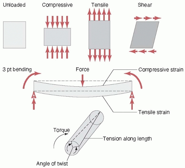
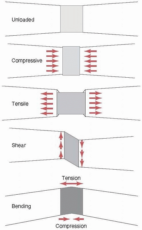
causes it to bow at the center. The forces and moments that act on a
long bone during functional use produce three basic stresses on the
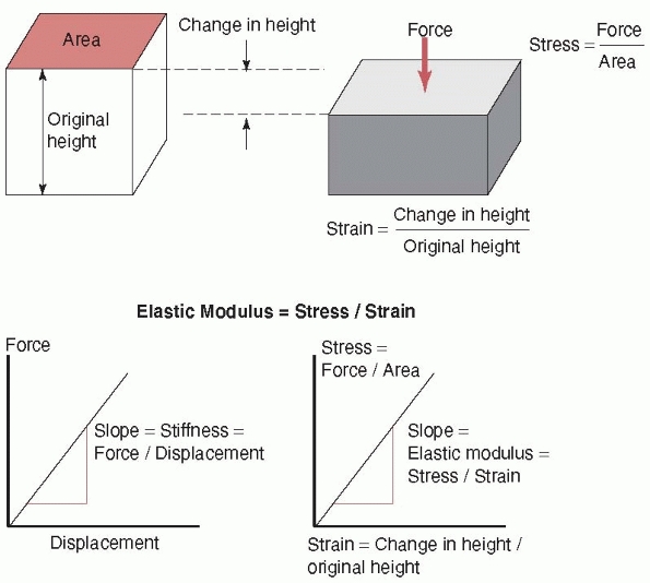
healing fracture region: tension, compression, and shear (as shown previously, all forces can be reduced to their basic components). Stress, as shown in Figure 1-4,
is simply the force divided by the area on an object over which it
acts. This is a convenient way to express how the force affects a
material locally. For example, comparing two bones, one with half the
cross-sectional area of the other, if the smaller bone is subjected to
half the force of the larger bone, the stress experienced by each bone
would be the same. Therefore, a smaller woman with less weight
has
proportionally smaller bones to keep the stresses on the bone tissue
similar to that of a larger and heavier man. The stresses acting on
fracture callus as a result of the different forces are shown (in an
idealized case) in Figure 1-5. Just as stress is normalized force (force per unit area), so can length changes be normalized. Strain
is simply the change in height or length that a bone undergoes during
loading divided by its original height or length, as shown in Figure 1-4.
Under the same force and for bones of similar composition, a bone twice
as long will experience twice the length change. Nevertheless, the
strain will be the same in both cases because the strain (in the longer
bone) will be twice the change in length divided by twice the original
length.
 |
|
FIGURE 1-2
In this example the outstretched arm is a lever. The moment or load that rotates the arm downward around the elbow, the center of rotation, is defined as the product of the weight of the object arm and hand X distance from the elbow (for simplicity the center of gravity of the hand, arm, and object are combined). This moment must be counteracted by a moment in the opposite direction, because of the vertical component of the biceps muscle acting through its lever, which is smaller than the lever arm of the weight arm and hand. The biceps force is then calculated from (10 kg × 24 cm)/3 cm = 80 kg. The biceps force is much greater than the weight of the object arm and hand because its lever arm is smaller. |
 |
|
FIGURE 1-3 Top:
Basic forces acting on a long bone and the deflection of the bone in response. Compression shortens the length, tension increases the length, and shear deforms the shape of the bone (middle), bending causes the bone to bow, and (bottom) torsion results in twisting about the long axis. |
 |
|
FIGURE 1-4
The stress is defined as the force acting on a surface divided by the area over which it acts. Strain is the change in height or length of the object under load divided by its original height or length. Stiffness is defined as the slope of a force versus displacement graph; that is, the change in force divided by the corresponding change in displacement. Elastic modulus is the corresponding slope but of a stress versus strain graph. |
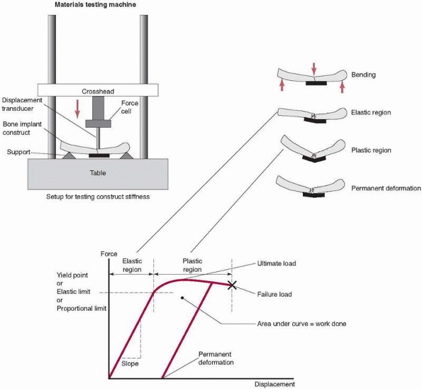
relate to the properties of the substances that make up each component
(bone, stainless steel, titanium). As load is applied to the construct
in a testing machine, the construct deforms. This deformation is termed
elastic because when the load is removed,
the construct will return to its original shape (an important
consideration in preventing malalignment of the bone fracture
components). At some load, however, the construct becomes overloaded,
entering the plastic
range. If the load is released after loading in the plastic range but before failure, some permanent deformation
remains in the construct. Practically, this represents a bent plate,
fixator, or rod and a malaligned fracture. The point at which elastic
behavior changes to plastic is termed the yield point.
The elastic range represents the working range for the fixation
construct. Its two most important properties are its yield point, which
defines its safe maximum functional load, and its stiffness, or the
amount it deforms under load in the elastic range. (A third very
important property, fatigue, will be discussed later.)
 |
|
FIGURE 1-5
Resulting stresses acting in fracture callus in a idealized case with each of the basic forces applied (top to bottom): unloaded, compressive stresses along the bone axis and expansive stresses perpendicular to the bone axis as a result of compression, tensile and contraction stresses caused by tension, distortion as a result of shearing; and tension on the convex side, compression on the concave side, and internal shearing caused by bending. |
points and stiffnesses for loads acting in different directions. An
example is a half-pin external fixator construct applied to a tibia,
with the pins oriented anterior-posteriorly. The stiffness is much
greater in anterior-posterior bending than medial-lateral bending for
this construct. Another property to consider is the work done
in deforming a fixation construct. The product of the force applied and
the distance the construct bends is defined as the work done, and is
represented by the area under the forcedisplacement graph of Figure 1-6. Toughness
can be defined as the work done to fracture a construct or material,
including both the elastic and plastic regions of deformation. A
material may be flexible and tough (e.g., rubber, or a child’s bone
that deforms but is difficult to break) or stiff but brittle (e.g.,
glass, elderly bone), if it cannot absorb much deformation without
fracturing.
the material from which the fixation device is made and its shape
(considering an ununited fracture in which the fracture callus
contributes little to structural properties). A construct made of
higher elastic modulus materials will be stiffer (for example,
stainless steel as compared to titanium). The stiffness of a construct
is found by dividing the force applied by the deformation that the
construct exhibited. The elastic (or Young)
modulus is determined by dividing the stress applied by the resulting
strain. Unlike whole constructs, in which case it is difficult to
determine stress (because it is hard to define the area over which the
force is applied and at least two different materials are involved),
uniform blocks of materials can be characterized by their elastic
modulus. The moduli of some common orthopaedic materials are given in Table 1-1.
As shown, the elastic modulus of titanium alloy is about one half that
of stainless steel, so given two plates of the same size and shape, the
titanium plate has about one half the stiffness of the stainless steel
plate. This can be important to consider when using new devices made of
different materials.
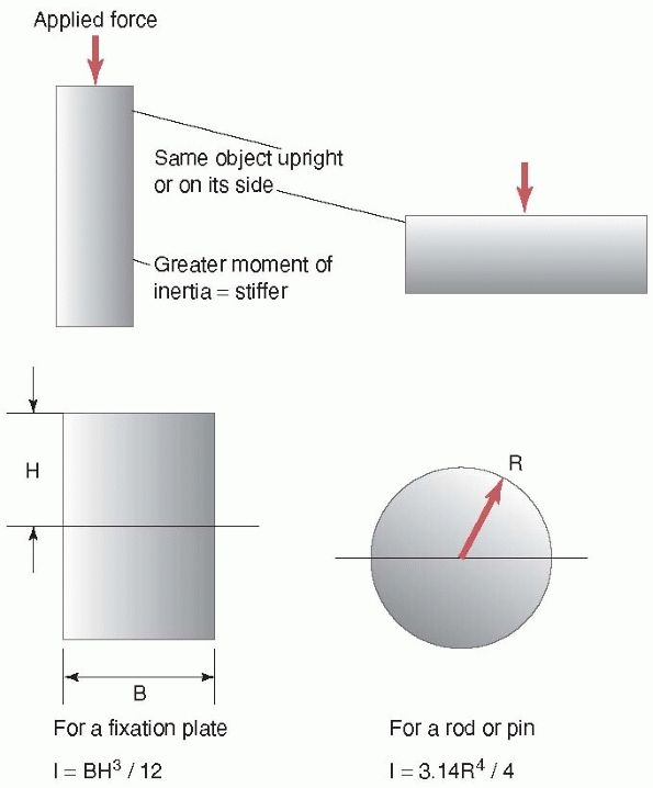
the same wooden 2 × 4 beam that bends easily when load is applied to
its wider surface becomes much stiffer when load is applied to its
narrower surface. This is because, in the latter case, the material of
the 2 × 4 resisting the load is distributed further away from the
center of the beam (note that in this example, the material of the beam
did not change, just its orientation relative to the load applied).
This concept of distribution of material is reflected in the shape
property, moment of inertia. The moment of
inertia provides a measure of how the material is distributed in the
cross section of the object relative to the load applied to it. The
farther away the material is from the center of the beam, the greater
its stiffness. Steel I-beams were developed to take advantage of this
concept; that is, gaining greater stiffness for the same amount of
material. For cylindrical objects like rods, pins, or screws, their
stiffness is related to the 4th power of their diameter. This is why,
as shown in Figure 1-7, for rods made of the
same materials and of similar thickness, a 16-mm diameter
intramedullary rod is 1.7 times as stiff as a 14-mm rod [(16/14)4], and a 7-mm diameter pedicle screw is 1.85 times as stiff as a 6-mm diameter screw.
under cyclic loading. Load can be applied that remains below the yield
point of the construct, yet progressively creates a crack that grows
until the local stress in the region of the crack exceeds the yield
point and the construct fails. Some materials have an endurance limit
such that they can support a certain level of load indefinitely without
failure. An important aspect to fatigue performance of a fixation
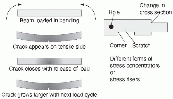
construct is the effect of a stress concentrator.
In completely uniform materials, the stresses, in tension for example,
will be almost identical throughout the material. Fixation devices have
holes, screw threads, and other features in which shape changes occur.
A very radical change in shape (as shown in Figure 1-8,
the sharp corner between threads of different diameter in a fixation
screw) causes a stress concentrator at the corner. This explains why
the
base of a screw thread, the place at which it meets the shaft of the
screw, has rounded corners. The stresses on a fracture construct are
increased when applied in heavier patients, with poor bone-to-bone
contact across the fracture site, delayed union, early weight bearing
before the fracture has united, and when smaller low-profile fixation
devices are used. For these circumstances, consider the use of larger
implants, taking care not to create stress concentrators by scuffing or
scratching the implant, and delay weight bearing until some fracture
consolidation is apparent. These steps can increase the amount of load
cycles that the implant can bear without fatigue failure.
 |
|
FIGURE 1-6 Top left:
A fixation construct (bone-fixation-bone) set up in a mechanical testing machine. In this example a long bone is fixed with a plate and subjected to bending. Top right: The construct during loading in the elastic region, plastic region, and with permanent deformation. Bottom: The resulting measurements from the testing machine, which measures force applied and displacement at the point of the applied load. The graph demonstrates the elastic region, in which the construct acts like a spring, returning to its original shape after the load is released; the plastic region, in which the plate may have permanently bent; and the failure load, in which the fixation fails. |
can occur. Stress corrosion combines the effects of the local growth of
the crack resulting from cyclic loading with galvanic corrosion. A galvanic cell
describes a local environment in which electrons flow from the more
negative to the more positive material when immersed in a liquid
conductor (saline in this case) (Fig. 1-9).
Material is actually removed from the more negative electrode, such as
the surface of the plate during galvanic corrosion. In a fixed
fracture, the dissimilar materials are the surface of the plate (for
example, stainless steel), which
creates
an oxide surface coating, and the same material within the just opening
crack, which has not yet developed the oxide film. The conductive fluid
is the blood and saline found in the surrounding tissues. Galvanic
corrosion can accelerate the failure of an implant, even when the
implant is loaded well below its yield point, by increasing the rate at
which the crack grows, because along with yielding at the site of the
crack, material at the crack is being removed by the corrosion process.
Another mechanism of corrosion, termed fretting,
results when the surfaces of two implants rub together, such as the
head of a screw against the surface of the plate through which it
passes. Crevice corrosion, which is not
common in modern orthopaedic materials, results from small galvanic
cells formed by impurities in the surface of the implant, causing
crevices as the material corrodes.23
|
TABLE 1-1 Basic Engineering Properties of Common Biologic and Implant Materials
|
|||||||||||||||||||||||||||||||||||||||||||||||||||||||||||||||||||||||||||||||||||||||||||||||||||||||||
|---|---|---|---|---|---|---|---|---|---|---|---|---|---|---|---|---|---|---|---|---|---|---|---|---|---|---|---|---|---|---|---|---|---|---|---|---|---|---|---|---|---|---|---|---|---|---|---|---|---|---|---|---|---|---|---|---|---|---|---|---|---|---|---|---|---|---|---|---|---|---|---|---|---|---|---|---|---|---|---|---|---|---|---|---|---|---|---|---|---|---|---|---|---|---|---|---|---|---|---|---|---|---|---|---|---|
|
|||||||||||||||||||||||||||||||||||||||||||||||||||||||||||||||||||||||||||||||||||||||||||||||||||||||||
 |
|
FIGURE 1-7 Concept of moment of inertia or the effect of the geometry of an object on its stiffness. Top:
Looking at the edge of a wood 2 × 4 (used in home building); left, the 2 × 4 with the load applied on the narrower side is stiffer than the same 2 × 4 with the load applied on its wider side. The area of the 2 × 4 is farther away from the central axis when the load is applied on the narrower side. Bottom: The moment of inertia is a term used to describe how the material is distributed within an object. Left, for a plate, looking at its edge, the moment of inertia and the stiffness increase directly with the width of the plate and the cube of its height. For a tube, such as an intramedullary rod, the moment of inertia increases with the 4th power of its diameter. Therefore a 16-mm diameter IM rod is 1.7 times as stiff as a 14-mm rod, and 2.3 times as stiff as a 13-mm rod, if all the rods have the same thickness and are made of the same material. |
 |
|
FIGURE 1-8 A stress concentrator is a region of an object in which stresses are higher than in the surrounding material. Left:
Taking the example of a fracture plate subjected to bending, the bottom surface elongates under load. In the region of highest tensile forces, a scratch starts to grow into a crack that closes when the load is released, then reopens slightly larger with the next load cycle, eventually growing to a point at which the plate fails. Crack growth is accentuated by stress corrosion, poor bone-to-bone contact at the fracture, and by loads applied by heavier patients. Right: Stress concentrators (sometimes referred to as stress risers) occur around holes, sharp corners, from scratches, and at corners from changes in cross section. |
 |
|
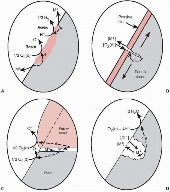
FIGURE 1-9 A.
Illustration of crevice corrosion, with a local galvanic cell caused by an impurity in the surface of a plate and ions, M+, being released, resulting in loss of material and formation of a crevice. B. Stress corrosion occurs by a local galvanic cell setup between the material at the tip of the crack, which just opened and has not oxidized, and the remaining oxidized surface of the plate. The released ions enhance crack growth occurring from loading. C. Fretting corrosion caused by the loss of the oxide layer on the surface of a plate caused by rubbing of the base of the screw against the plate. D. Galvanic corrosion around a scratch or pit in the plate.23 |
Biologic materials do not act as pure springs when load is applied to
them. (A spring deforms under load, then returns to its original shape
when the load is released.) For example, if a load is applied to a
tendon, and the load is maintained for a period of time, the tissue
will continue to deform or creep. This is
the basic principle behind stretching exercises. Under a constant load,
a metal fixation plate will deform and remain at that deformation until
the load is removed (elastic behavior). In contrast the tendon both
deforms elastically and creeps, exhibiting both viscous and elastic
behavior. This property has important implications for certain types of
fixation, especially those that rely on loading of
soft tissues, such as in certain types of spinal fixation (to be discussed later).
In simple terms, stretching a soft tissue can be thought of as
stretching two components, an elastic one and a viscous one, which make
up that tissue. For example, consider a spring connected in series to
the handle of a syringe (Fig. 1-10). When a
compressive force is applied, the spring instantly compresses,
representing the elastic response of the tissue. The syringe plunger
starts to displace and continues as it pushes fluid through the
orifice. If the force is held constant, the plunger will continue to
move, representing the viscous creep of the tissue. If the compressive
force is applied slowly, the syringe handle offers little resistance.
As the rate of force application increases, the resistance of the
syringe to motion increases. This represents the increase in stiffness
of the tissue at higher loading rates. That is, the stiffness of the
tissue depends upon the rate at which the load is applied.
to failure of ligament and bone. At low loading rates, ligament is
weaker than bone and the ligament fails generally in midsubstance. At
higher loading rates, the ligament becomes stiffer, and failure may
occur by avulsion of the bony attachment of the ligament. Stress relaxation
occurs if the applied force, instead of increasing, is held constant.
As the fluid flows out of the syringe, without further movement of the
plunger, the internal force decreases. These three properties—creep,
stress relaxation, and load rate dependence—make up the basic tissue
viscoelastic properties. It should be appreciated that the model used
in this discussion is a simple linear series model, for explanation
purposes only. Nevertheless, more complex models using combinations of
these basic components have successfully described the observed
properties of tissues. Another example of tissue viscoelasticity,
besides tendon and other soft tissues, is found in trabecular bone (for
example, spinal vertebrae). In this case, the trabecular structure acts
as the spring component, while forcing the interstitial fluid through
the porous matrix as the trabeculae deform represents the viscous
component. Under higher loading rates, there is resistance to flow,
increasing the internal pressure and therefore the stiffness of the
structure. These effects have been observed at high loading rates, such
as during fracture (Fig. 1-11).32
 |
|
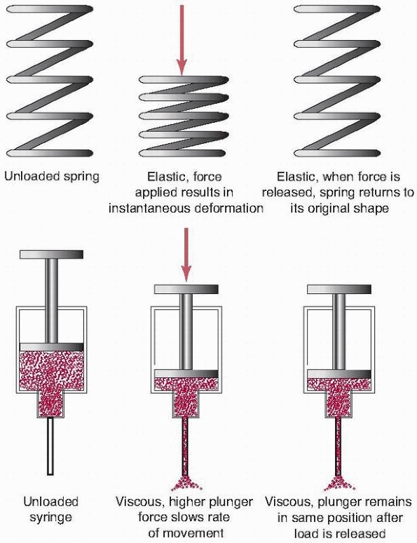
FIGURE 1-10
Viscoelastic response in a biological tissue can be explained by considering and combining the properties of two devices, a simple spring and a fluid-filled syringe. The elastic or spring component instantly compresses when a load is applied to it. When the load is released, the spring returns to its original shape. When a load is applied to the viscous component, represented by the syringe, fluid is forced out the needle. If the load is released, the plunger does not return, but remains in its final position, representing the creep property of the tissue. Further, if the force is applied to the plunger more rapidly, there is greater resistance to motion, explaining the increased stiffness of tissue to increased rates of loading. Combinations of these simple components can be used to describe the mechanical properties of biologic tissues. |
forces, but these forces can be resolved into basic components that
create tension, compression, shearing, twisting, and bending. These
forces cause internal, compressive, tensile, and shear stresses in the
tissue. The stiffness of a fixation construct used to stabilize a
fracture describes how much it deforms under a given load acting in a
specific direction. Stiffness may vary with direction and is highly
dependent on the shape of the fixation construct. The effect of shape
is described by the moment of inertia. In combination with the moment
of inertia, the elastic modulus of the material describes how stiff the
fixation will be under load, and its ability to withstand the forces
of, for example the patient’s weight during ambulation. Failure of
fixation can come not only from loading above its yield point but also
as a result of repetitive stress. Repetitive loading can cause growth
of a crack at a stress concentrator, and can be significantly
accentuated by corrosion when the implant is immersed in bodily fluids.
Biologic tissues behave viscoelastically; that is, they creep under
constant load, stress relax when the elongation is fixed, and increase
in stiffness as the rate of load application increases.
In this chapter, these mechanical properties are described in basic units of measurements, defined in Table 1-2.
 |
|
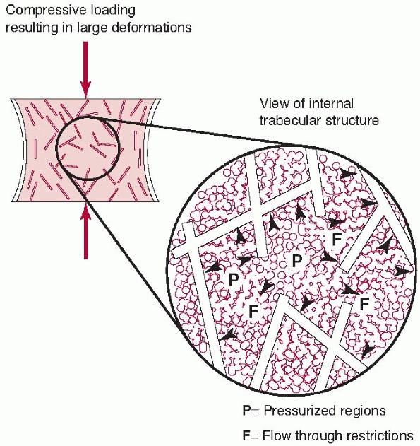
FIGURE 1-11 Trabecular bone possesses some features of the spring and syringe viscoelastic model described in Figure 1-10,
although it should be appreciated that this is an idealized model. The trabecular structure acts as the spring element. At higher loading rates, the interstitutial fluid resists flowing through the trabecular spaces, causing increased internal pressure and greater bone stiffness. This anatomical feature allows vertebrae and the metaphyseal ends of long bones to resist dynamic loads caused by rapidly applied forces.32 |
 |
|
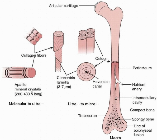
FIGURE 1-12
The hierarchical structure of bone is demonstrated. At the lowest level of organization, the ratio of mineral crystals to collagen fibrils determines elastic modulus of the combined material, as shown in Figure 1-13. At the next level, the fiber orientation is important in determining the difference in strength of bone in different directions. At the final level, the lamella of bone fibers form haversian systems that, particularly in cortical bone, are oriented in the direction of the major loads the bone must support. |
|
TABLE 1-2 Definitions of the Units Used to Describe the Basic Properties of Fracture Constructs
|
|||||
|---|---|---|---|---|---|
|
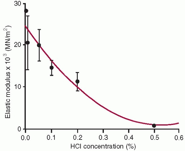
the lowest level of the structure consists of single collagen fibrils
with embedded apatite crystals. At this level of structure, changing
the collagen to mineral ratio has a significant effect on the elastic
modulus of bone,30,32,42 because it decreases with loss of mineral (Fig. 1-13).
This is important from a fracture healing perspective because
mineralizing healing callus goes through phases of increasing mineral
density and corresponding increased modulus as healing occurs. At the
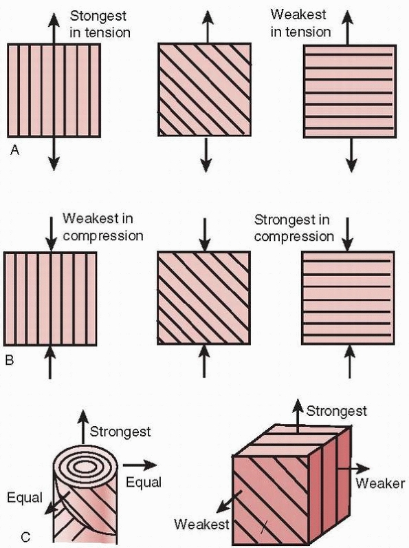
next level of structural organization, the orientation of the collagen
fibrils is important.9,10,11,12,55,56,57 As demonstrated in Figure 1-14, the orientation of its fibers affects the ability of bone to support loads in specific
directions. During fracture healing, the callus initially starts as a
disorganized random array of fibers, which progressively reorganize to
become stiffest along the directions of the major applied loads (body
weight and muscle forces) to which the bone is exposed. At the next
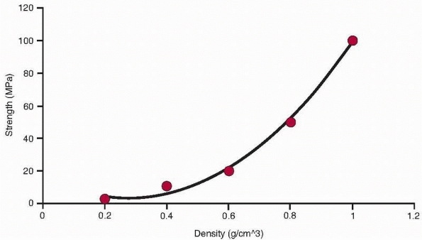
level, the density of the haversian systems affects bone strength. It
has been repeatedly demonstrated that a power law relationship exists
between bone density and strength at this level of structure (Fig. 1-15).
This means that as bone density decreases, its strength decreases as
the square of its density (as density decreases by half, strength
decreases by a factor of 4). This forms the basis for predicting
changes in bone strength as a result of conditions such as
osteoporosis. Similarly, the modulus changes with bone density by a
power of between 2 and 3.19,21,29,35,62
Noninvasive measures of bone density such as quantitative computed
tomography (qCT) have been shown to have a significant predictive
relationship to bone strength.3,43,44,103
 |
|
FIGURE 1-13
Elastic modulus of bone samples tested in tension after exposure to different concentrations of HCl. Greater HCl concentration progressively demineralizes bone, ultimately leaving only collagen. This diagram illustrates the contribution of bone mineral to the tensile elastic modulus of whole bone.30 |
 |
|
FIGURE 1-14 Effects of collagen fiber direction on the resistance to loads applied in different directions. A. Under tensile loading, the strongest arrangement is having the collagen fibers parallel to the load. B. Under compressive loading, the strongest arrangement is having the collagen fibers perpendicular to the load. C.
In bone that must accommodate different loading directions, the arrangement of the haversian system produces one strongest direction along the axis, with proximately equal strengths in other directions.57 |
bone. As discussed previously, bone is a viscoelastic material whose
strength and modulus both increase as loading rate increases (for
example, in fracture impact loading as compared with normal ambulation).29,38,39,40,108,163
The geometry of bone, specifically the size of the cross section and
thickness of the cortex, affects its moment of inertia and therefore
its strength.124 Age also affects
bone properties. The bending strength and modulus increase as bone
mineralizes and matures from childhood to adulthood and slowly decrease
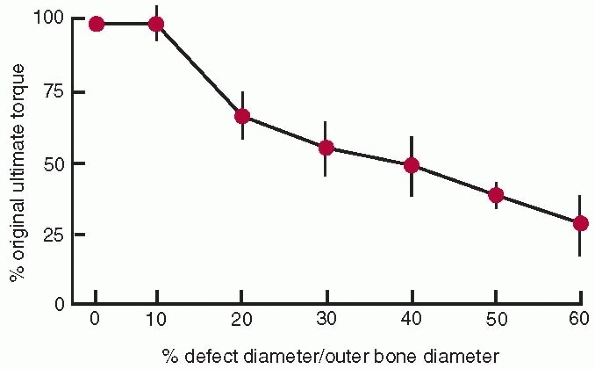
thereafter39,43,157 and the capacity to absorb impact energy decreases with age41 as bone becomes more brittle. Defects or holes in bone (for example from drilling for screws) also affect its strength.27,30,47,97,106 The torsional strength of bone decreases as the diameter of the hole or defect increases (Fig. 1-16).
As the hole increases in size to 30% of the diameter of the bone, bone
strength decreases to about 50% of that of the bone without a defect.
An important consideration, applicable in the resection of bone (such
as in removal of a tumor) is the shape of the hole or defect left after
tumor removal. Leaving a hole with square corners significantly
decreases bone strength compared to the same hole with rounded corners,
because the square corner is a large stress concentrator. Oval or
circular holes, while themselves still stress risers, do not contribute
the additional effect of the sharp corner.34 Table 1-3 summarizes the strength of cortical and cancellous bone material as well as the ultimate strengths of various whole bones.
in its mineral content, callus diameter, and fiber organization, as
discussed previously. The initial callus forms from the periosteal
surface outward, which is beneficial mechanically, because as the outer
diameter of the healing area enlarges, its moment of inertia and
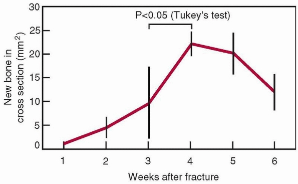
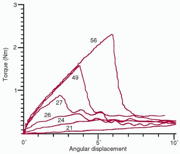
therefore its initial stiffness both increase, as shown in Figure 1-17.122 The cross-sectional area increases progressively, as shown in Figure 1-18, as does the mineral content of the callus.8 The mechanical results of these changes to bone as the fracture heals are shown in Figure 1-19.
From torsional tests of healing rabbit long bones, progressive
increases were observed in stiffness and peak torque to failure with
time.159 Interestingly, in that
experiment, the stiffness appeared to gain normal values before the
peak torque to failure, showing that stiffness and strength are related
but not directly. Figure 1-19 shows that beyond 4 weeks (in rats, whose bones heal rapidly),
the cross-sectional area starts to decrease as the bone remodels to normal shape, while the bone tissue continues to mineralize.
 |
|
FIGURE 1-15
The relationship of trabecular bone density to compressive strength and modulus demonstrates a power law relationship so that these properties decrease by a factor of about 4 when density decreases by half.32 |
system along with the available blood supply affects the type of tissue
formed in a healing fracture. The theory of interfragmentary strain
attempts to relate the types of tissues formed to the amount of strain
experienced by the tissue between the healing bone fragments.122
This theory is a simple representation and cannot describe the complex
stresses that the tissue is exposed to during actual healing.
Nonetheless, within the limitations of the theory, when large strains
occur in the tissues between healing bone surfaces, granulation tissue
is formed. Intermediate level strains produce cartilage and small
strains result in primary bone healing, or direct deposition of bone
tissue with limited callus formation.
 |
|
FIGURE 1-16
The relationship of ultimate torque (failure torque) of a long bone to the diameter of the hole divided by the outer diameter of the bone. There is no change in ultimate torque until the defect size increase beyond greater than 10% of the diameter of the bone.47 |
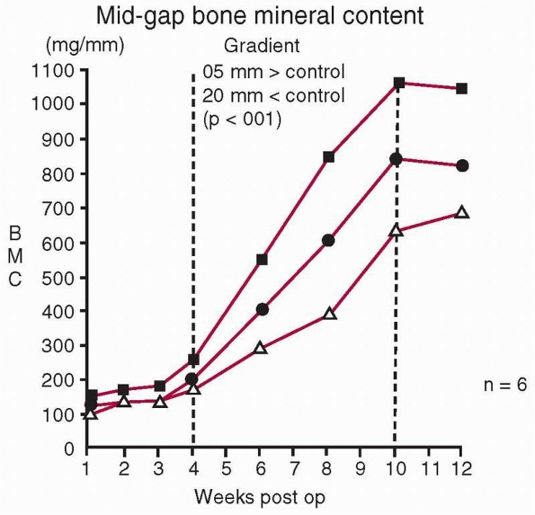
recognize that it doesn’t follow that zero strain will result in
maximum bone formation. Load and some resulting strain are necessary
within the healing fracture to stimulate bone formation. In a study in
which controlled daily displacements in compression were applied to
healing long bones using an external fixator, and the bone mineral
within the healing fracture was measured with time, there was an
optimal displacement above or below which less mineral was created in
the fracture callus (Fig. 1-20).158 Further, compression rather than tension is the preferred direction of loading.16
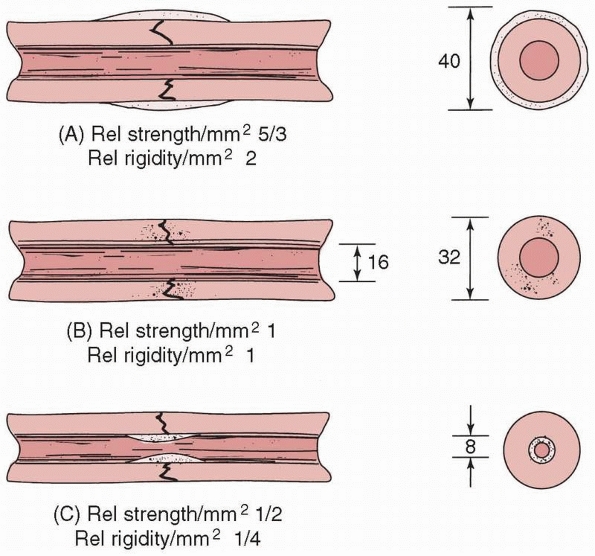
Fracture fixation constructs of different stiffnesses within a certain
range produce healed fractures with similar mechanical properties,
however, they may reach this endpoint by different routes. In a study
of femoral fixation using intramedullary rods of either 5% or 50% of
the torsional stiffness of the intact femur, the femurs fixed with the
lower stiffness rods produced an abundance of stabilizing callus, as
opposed to the femurs with more rigid fixation, see Figure 1-21.
This is because with more rigid fixation there was less necessity for
biological fracture stabilization. In both cases, however, the
mechanical properties of the healed fractures were ultimately similar.162
These studies demonstrate that some strain as a result of loading the
fracture stimulates healing, and that bone will adapt and heal within a
relatively wide range of mechanical stability environments.
and healing fractures. Increasing mineral content increases fracture
stiffness. Callus that forms on the periosteal surface is beneficial in
increasing the moment of inertia and therefore the stiffness of the
fractured region. Healing fractures exhibit several stages, with
stiffness returning to normal followed later by peak load to failure.
Bone will heal within a range of mechanical environments. To a certain
extent, healing bone will compensate for more flexible fixation by
forming a greater quantity of fracture callus; however, there is a
range of loading of a healing callus, sufficient to stimulate bone
formation, which increases as the callus matures.
tension and strongest in compression. Therefore, when a force creates
tensile stresses in a particular region of a loaded bone, failure will
generally occur first in that region. The simplest example, shown in Figure 1-22,
is the transverse fracture created in a long bone subjected to pure
bending. Because in this example the upper, convex surface undergoes
the greatest elongation, it is subjected to the largest tensile
stresses, and failure, indicated by a crack, initiates here. The crack
then progresses transversely through the material, and layers just
below the outer layer become subjected to high tensile stress until
they crack as well. In this manner, the crack progresses through the
bone transversely until it fails. The concave surface is subjected to
compression so the crack does not initiate there. A second example is
the fracture line or crack that occurs when a bone is subjected to
torsion or axial twisting. In those cases, a spiral fracture results.
Consider, as shown in Figure 1-22, a
rectangular area on the surface of a long bone that is loaded in
torsion. The rectangle distorts as the bone twists, with one diagonal
of the rectangle elongating and the other shortening, depending on the
direction of twist. A crack will form perpendicular to the diagonal
that is elongating, and progresses around the perimeter of the bone
resulting in a spiral fracture. The region of bone with the smallest
diameter is usually the least stiff region, resulting in the greatest
distortion of the surface and is generally the location of the
fracture. This explains why torsional fractures of the tibia often
occur in the narrow distal third, see Figure 1-23.
|
TABLE 1-3 Mechanical Properties of Bone Material and Whole Bones in Different Loading Directions
|
||||||||||||||||||||||||||||||||||||||||||||||||||||||||||||||||||||||||||||||||||||||||||||||||||||||||||||||
|---|---|---|---|---|---|---|---|---|---|---|---|---|---|---|---|---|---|---|---|---|---|---|---|---|---|---|---|---|---|---|---|---|---|---|---|---|---|---|---|---|---|---|---|---|---|---|---|---|---|---|---|---|---|---|---|---|---|---|---|---|---|---|---|---|---|---|---|---|---|---|---|---|---|---|---|---|---|---|---|---|---|---|---|---|---|---|---|---|---|---|---|---|---|---|---|---|---|---|---|---|---|---|---|---|---|---|---|---|---|---|
|
 |
|
FIGURE 1-17 A comparison of the moments of inertia and resulting strengths when fracture callus is located (A) on the outer surface, (B) on the bone surfaces, or (C)
in the medullary canal. The strength and rigidity are significantly increased when callus is located over the periosteal surface, compared to within the medullary canal.118 |
 |
|
FIGURE 1-18
Changes in the cross-sectional area of a healing femoral fracture, which peaks and slowly decreases. There is a similar increase in the mineral content. (The data come from rats, which heal more rapidly than humans, indicated by the 4-week time to peak mineralization.8) |
 |
|
FIGURE 1-19
A comparison of superimposed torque-angular displacement plots taken from experimental long bones at different stages of healing shows the significant increase in both stiffness and peak torque to failure with increased duration of healing. Numerical values are time in days postfracture in rabbits.159 |
 |
|
FIGURE 1-20
The effect on bone mineral of different cyclic displacements applied daily within a healing fracture (upper curve, 0.5 mm; middle curve, 1.0 mm; lower curve, 2.0 mm for 500 cycles/day). This shows that some displacement (in this experiment, 0.5 mm) stimulates bone formation, but that greater displacements (1.0 mm and 2.0 mm) do not enhance bone formation. These results point to an optimal range of displacements for maximum bone formation.158 |
 |
|
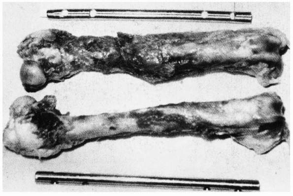
FIGURE 1-21 A comparison of the different healing responses of dog femurs with midshaft fractures fixed with (top) IM rods of 5%, or (bottom)
50% of the torsional stiffness of the intact femur. The femurs fixed with rods of lower stiffness produced more callus as additional stabilization against functional loads, but there was ultimately no difference in mechanical properties between the femurs fixed with rods of different stiffnesses.162 |
 |
|
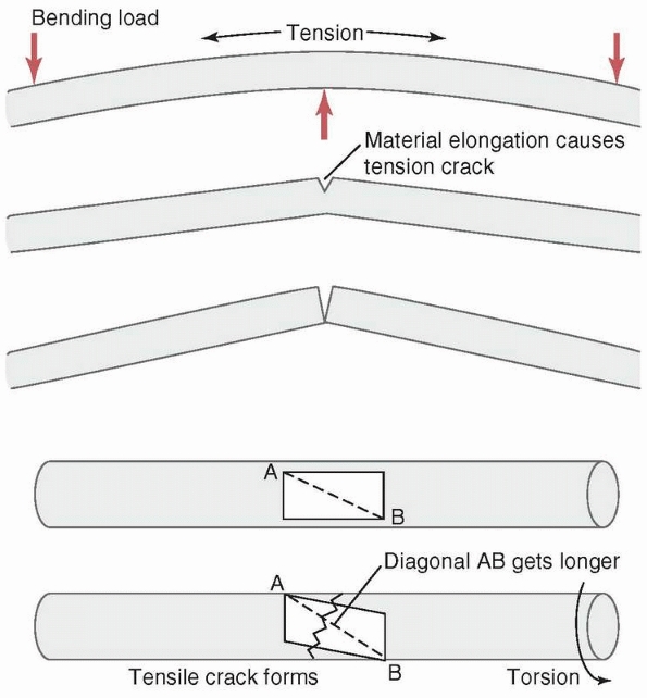
FIGURE 1-22 Top:
A transverse fracture is created by the progressive tensile failure of bone material starting from the convex surface in which elongation and therefore stress is greatest, with the crack progressing to the concave side. Bottom: A spiral fracture is created by the progressive failure in tension of fibers on the bone surface along the diagonal that elongates as the material on the surface distorts when torque is applied. (A rectangle on the surface becomes a parallelogram, with one diagonal elongating. The crack will be transverse to the diagonal.) |
 |
|
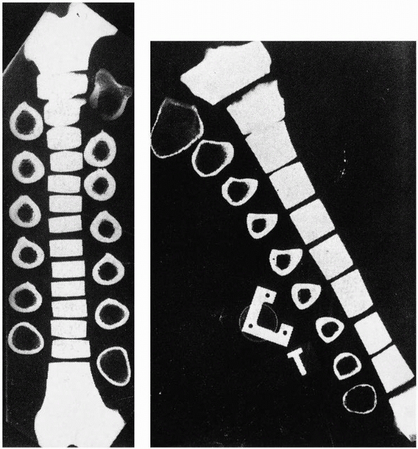
FIGURE 1-23 Cross sections through (left) a femur, and (right)
a tibia. The small cross section of the distal third of the tibia results in more distortion and higher stresses and explains why torsional failure often occurs in this area. |
by shear, indicated by slippage along the diagonal, because bone is
weaker in shear than in compression (Fig. 1-24).
In this case, compressive loading causes an interface within the bone
at 45 degrees to the applied load to slide along another at an oblique
angle. At very high loads, such as during impact fractures, crushing or
comminution of bone also occurs, especially at the weaker metaphyseal
ends of a long bone. The trabecular bone at the metaphyseal ends is
weaker in compression than the diaphyseal cortical bone is in shear.
Because of this, it is unlikely that shearing failure will occur in the
diaphysis caused by pure compressive forces. The butterfly fracture (Fig. 1-24)
results from combined bending and compression. Bending load causes the
fracture to start to fail in tension producing a transverse crack, but
as the crack progresses and the remaining intact bone weakens, it
starts to fail in compression, causing an oblique (shear) fracture
line. As the ends of the failing bone are driven together, a third
fragment—the butterfly—may result as the
oblique
fragment splits off. The production of a butterfly fragment probably
depends on the timing and magnitude of the two basic applied loads:
compression and bending.
 |
|
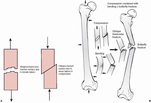
FIGURE 1-24 A. Left:
Tensile fracture causes a stepped surface as fibers pull apart. The crack progresses, then steps to an adjacent region in which failure continues. Right: Pure compression of cortical bone results in failure by shearing or sliding along oblique surfaces. In reality, pure compression of a long bone (in a fall for example) results in crushing of the much weaker metaphyseal trabecular bone with a pilon fracture of the distal tibia or a tibial plateau fracture as the result. B. Some fractures that combine bending and compression demonstrate transverse cracking as a result of bending followed by an oblique crack characteristic of compressive failure. The butterfly fracture with additional splitting of the fragment secondary to the initial fracture is an example. |
force required to fracture bone and the types of fractures that occur.
As shown in Figure 1-15, trabecular bone
stiffness varies with the cube (3rd power) of its density and strength
approximately with the square of its density.32
Bone mass normally peaks around age 25 to 30 years and decreases up to
1% annually thereafter. If the density of trabecular bone is decreased
by 30% in a 60- to 70-year-old as a result of osteoporosis, the bone
compressive strength is about half of that of a 30-year-old. Typically,
fractures as a result of osteoporosis occur in the vertebrae, the
distal radius, and the femoral neck. In addition, osteoporosis changes
the cross-sectional shape of long bones, decreasing thickness by
increasing the endosteal diameter while causing the periosteal diameter
to increase. If cortical outer diameter—for example, in the
femur—increased and cortical thickness decreased at the same rate, the
moment of inertia of the bone cross section would be larger. That is
why large-diameter thin tubing can be substituted for smaller diameter
thicker tubing in structures (for example, sailboat masts), saving
weight while not sacrificing strength. However, in the femur, the inner
surface of the cortex also becomes more irregular and porous,
decreasing its material strength. A common result of loss of femoral
bone mass combined with other factors, such as poor balance, is a hip
fracture usually resulting from a fall.1
mechanisms have been observed. Fracture of the calcaneus or the
malleoli of the foot and ankle can occur through a combination of the
foot being forced against the brake pedal by the weight of the occupant
during a high speed frontal collision, or in combination with the floor
pan of the auto crushing into the space in which the foot resides.127
Drivers who were braking during a crash were shown to be much more
likely to injure their right foot compared with their left foot.15
If the Achilles tendon applies load to resist the forced dorsiflexion
of the foot on the brake pedal, the combination of these two loads make
cause three point bending loading of the calcaneus, with the posterior
facet of the talus as the fulcrum. A crack initiates on the plantar or
tensile side of the calcaneus and a tongue type calcaneus fracture can
occur. Inversion or eversion, in which the foot is not securely planted
on the brake pedal and rotates with compression, is likely to result in
a malleolar fracture,61
although the combinations of forces causing these high energy fractures are not entirely predictable.
with the dashboard of the vehicle in a frontal collision, especially
for unrestrained drivers who submarine or slide forward in the seat.154 Tensing the quadriceps and hamstrings muscles during a crash applies significant additional compression along the femur.154
The anterior bow of the femur causes the external compressive force
from contact of the knee with the dashboard, and internal muscle forces
to bend the femur, resulting in bending and transverse or oblique
fractures. If the femur of the occupant hits the dashboard in an
adducted orientation, the femur can be displaced from the acetabulum,
causing a fracture of the acetabular roof and dislocation of the hip
joint. Pelvic fractures result from loading in side impact crashes, in
which the door punches inward against the hip and pelvis. The actual
fracture pattern (symphysis, sacroiliac joint, or both) is probably the
result of the specific alignment of the pelvis with the applied loads
at impact. Pelvic fracture classifications are based on the presumed
mechanism of injury and specific forces applied.139,141,166,167
Bilateral hip fractures have been found to occur in crashes in which
the vehicle has a large center console that tends to trap the pelvis as
force is also applied on the hip opposite that which contacts the door.
Auto crashes also create, in occupants with lap but not shoulder belts,
the classic “Chance fracture,” which is combined compression and
flexion failure of a lumbar vertebra, usually at the level in which the
lap belt forms a fulcrum. Upper extremity injuries in auto crashes have
been found to be related to airbag deployment and entrapment of the arm
in the steering wheel.65
devices for skeletal fracture fixation are discussed. Observed fixation
problems with devices such as wire, cable, screws plates, IM rods, and
external fixators are explained with the objective of reducing the
potential for mechanical damage or failure of these devices during use.
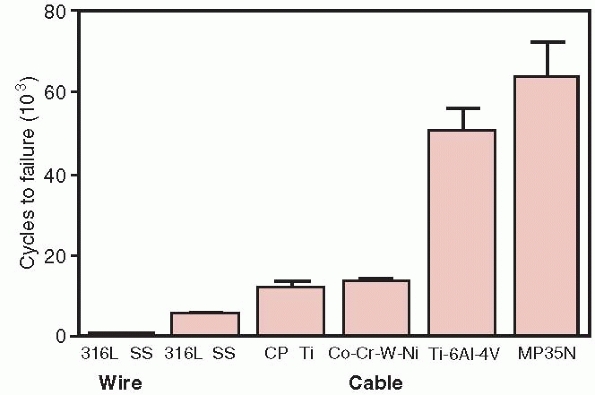
However, solid wire is very sensitive to notches or scratches. Testing
shows that notches as small as 1% of the diameter of the wire can
reduce its fatigue life by 63%.132
For this reason, cable has been introduced for cerclage applications.
Cable has significantly better fatigue performance compared to wire, as
shown in Figure 1-25.64
Because cables consist of multiple strands of single thin wires, damage
to any particular strand does not result in failure of the whole cable.
Single loops of suture such as Ethibond are about 30% as strong as
18-gage stainless steel wire in tension, and Merseline tape is about
50% as strong. Four loops of Ethibond were shown to have tensile
strength equivalent to stainless steel wire.70
 |
|
FIGURE 1-25
A comparison of the fatigue resistance of wire and cables made of the indicated materials. Wire, 316 SS (stainless steel), cable 316 SS, Cp Ti, commercially pure titanium, Co-Cr-W-Ni, cobalt chrome, Ti 6Al 4V, titanium alloy, MP35N, nickel alloy.64 |
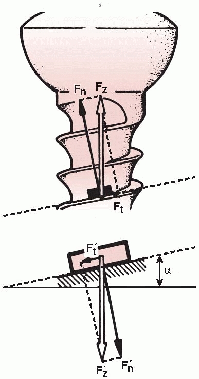
rotary load (torque) into compression between a plate and bone, or
between bone fragments. As shown in Figure 1-26,
the thread of a screw, if unwound from the shaft, is really a ramp or
inclined plane that pulls, for example, underlying bone toward
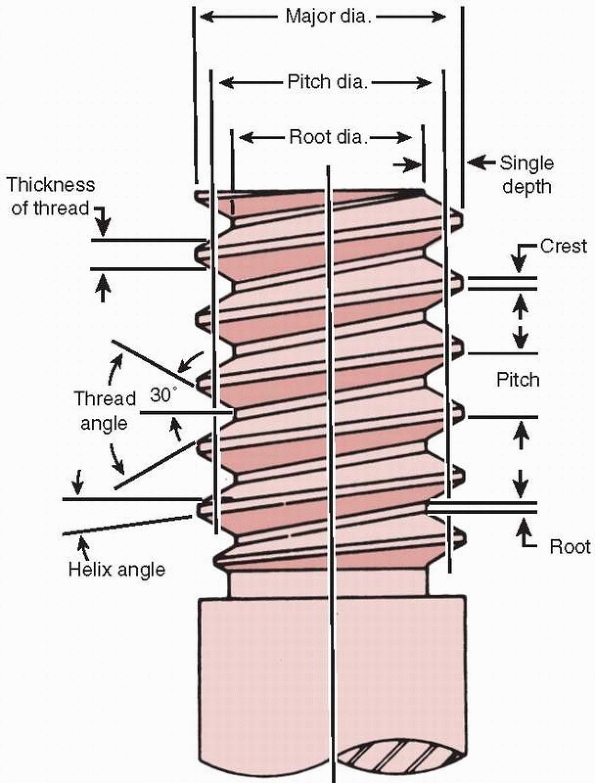
the fixation plate, causing compression between them.123 The basic components of a screw are shown in Figure 1-27.
Because of its function, the screw head and shaft should be free to
turn in the plate; otherwise the compressive force generated may be
limited. (This doesn’t apply to screws that are designed to be threaded
into the plate holes in locking plates.) One common problem is that
sometimes threads are tapped into both bone components. The bone
component in which the screw head will rest should be drilled oversize
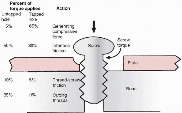
to allow the shaft of the screw to turn freely. Tapping is necessary in
cortical bone so that the torque applied by the surgeon is converted
into compression instead of cutting threads and overcoming friction
between the screw thread and bone (Ft in Figure 1-26) that it is being driven into (Fig. 1-28).75
At the same time, self-tapping screws are available and, when used,
those with multiple cutting flutes at the tip of the screw appeared to
be the easiest to insert and had greater holding power.165
With cancellous bone, as discussed later, tapping is less advantageous,
unless the bone is very dense. One common problem during screw
placement is shear failure of the screw, typically the head twisting
off leaving the shaft embedded in bone and difficult to remove. This
can occur especially when using smaller (less than 4 mm diameter)
screws in dense bone, especially without tapping. The stiffness and
strength of a screw are related to the 4th power of its diameter (the
effect of moment of inertia, for screws of the same material). A 6-mm
diameter screw is approximately 5 times as stiff as a 3-mm diameter
screw and 16 times as resistant to shear failure by over-torquing the
screw during insertion.
 |
|
FIGURE 1-26
A screw is a mechanical device that converts torque into compression between objects. The screw thread is actually an inclined plane that slowly pulls the objects it is embedded into together. For this reason, the head and screw shaft in one part must be free to rotate. If this part of the screw is threaded into the hole of the first part (for example, the plate) it will not allow the surfaces to compress (Fn, normal or compressive force acting against the screw head; Ft, tangential or frictional force acting along the screw thread; Fz, resultant of the two forces, α, angle of the screw thread. The smaller the angle α [finer thread] the lower the frictional force). |
 |
|
FIGURE 1-27
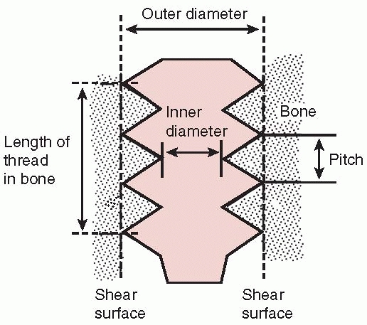
Nomenclature of screws. The root diameter is the inner diameter of the screw and the pitch defines the distance between threads. |
 |
|
FIGURE 1-28
Schematic diagram showing the approximate distribution of torque acting on screw placed into cortical bone. With a pretapped hole, about 65% of the applied torque goes to produce compression and 35% to overcome the friction associated with driving the screw. When the hole is not tapped, only about 5% of the torque is used to produce compression, the rest going to overcome friction and to cut threads in bone. These observations do not apply in cancellous bone. |
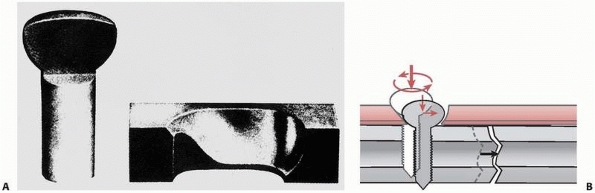
a screw can withstand along its axis, the pullout force, depends upon
the size of the screw and the density of the bone it is placed into. As
shown in Figure 1-29, when the force acting on
the screw exceeds its pullout strength, the screw will pull or shear
out of the hole, carrying the sheared bone within its threads, because
it is usually the bone that fails and not the screw. The pullout force
increases with larger screw diameter, a longer embedded length of screw
shaft, and greater density of the bone it is placed into.33,45,58,134
The diameter and length of the embedded screw can be thought of as
defining the outer surface of a cylinder along which the screw shears.
Given the maximum stress that bone of a particular density can
withstand, increasing the surface area of the screw cylinder increases
the pullout force (because force = stress × area over which it acts).
To enhance screw purchase, consider embedding the largest diameter
screw possible into bone of the greatest density over as long a
purchase length as possible.33,45 Pullout strength also increases significantly if the screw is placed through both bone cortices.
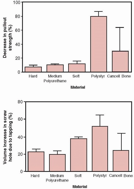
problem because the porosity of cancellous bone reduces its density and therefore its shear strength.148
Hole preparation, specifically drilling but not tapping, improves the
pullout strength of screws placed into cancellous bone (such as pedicle
screws in the vertebral body).33 The reason that tapping reduces strength in cancellous bone, as shown in Figure 1-30,
is that running the tap in and out of the hole removes bone,
effectively increasing the diameter of the hole and reducing the amount
of bone material that interacts with the screw threads. Tapping has
more effect as bone density decreases and can reduce the pullout
strength from 10% to as much as 30%. It should also be noted that the
findings of studies related to pullout strength relate to the time
immediately after insertion. As the bone heals, it also remodels around
the screw, possibly doubling its initial pullout strength.134
 |
|
FIGURE 1-29
The factors that determine the pullout strength of a screw are its outer diameter and length of engagement (this defines the dimensions of a cylinder of bone that is carried in the threads and is sheared out as the screw is pulled out of bone) and the shear strength of bone at the screw/bone interface, which is directly related to its density. A finer pitch screw produces a small gain in purchase.33 |
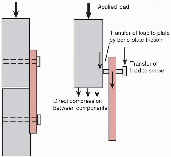
This mode of loading could occur during functional use; for example,
with a dynamic compression plate (DCP) but not a locking plate. The
screw should be tightened against the DCP plate to the maximum extent
possible and the tightening torque effectively transferred to
compressive force between plate and bone (see Fig. 1-28).
The screw holds the plate against bone partly by frictional contact,
which depends on the frictional force generated between the
undersurface of the plate and bone. The frictional force is directly
dependent on the compressive force generated by the screws. If any
sliding occurs between the plate and bone, bending load will be
transferred from the head of the screw into the plate, where
screw-plate contact occurs. Bending loads perpendicular to the axis of
the screw, along with possible stress corrosion and fretting corrosion,
may cause the screws to fail rapidly in fatigue. Zand et al168
showed that screws tightened against a plate with only 10% to 15% less
force than the maximum possible failed in less than 1000 loading
cycles, by bending fatigue, compared with fully tightened screws that
were able to sustain over 2.5 million loading cycles. Screws that lock
into the plate reduce this problem. Small fragment screws, around 4 mm
outside diameter, can fatigue because their core diameters are small.
The trade-off in use of these devices is choosing a screw with a larger
core diameter and shallower thread to reduce the possibility of
fatigue, or a smaller core diameter and deeper thread to increase
purchase strength in bone.111
 |
|
FIGURE 1-30 Top:
The decrease in pullout strength in various types of foam used to test bone screws demonstrating the percentage decrease in pullout strength between screws placed into holes that were either drilled only or drilled and tapped. Bottom: The percentage increase in volume comparing holes that were drilled only and those that were drilled and tapped. Tapping in cancellous bone increases hole volume, which decreases pullout strength.33 |
the significant advantage that they can be precisely guided into
position over a guide wire, which itself may aid in reduction of a
fracture fragment. Nevertheless, drilling precision for the screw or
guide wire is decreased with increasing density of bone, and the use of
longer and smaller diameter drill bits.74
Cannulated screws follow the same mechanical principles as solid
screws, however, to create the central hole, material must be removed
from the center of the screw. Manufacturers commonly increase the minor
diameter (the diameter of the screw at the base of the thread) to
accommodate the loss of this material. The same size cannulated screws
usually have less thread depth compared with solid screws. The
result—depending on the screw size—is less pullout strength. For 4-mm
diameter screws, cannulated screws of the same outside diameter had
about 16% less pullout strength.151 Alternatively, to keep the same thread depth, the outer diameter of the screw may be increased.
 |
|
FIGURE 1-31
A mechanism for rapid failure of screws in cyclic bending occurs when the screw has not been tightened sufficiently to keep the plate from sliding along the bone surface (the plate-bone gap shown here is exaggerated for clarity). The result is that bending loads are applied transverse to the long axis of the screw, which in combination with fretting corrosion caused by the screws rubbing against the plate results in early failure of the screw. |
fracture by driving the ends of the fracture together, compressing
them. This is beneficial to fracture healing because it improves
stability, opening the possibility for primary bone healing with
minimal callus formation, and by enhancing the resistance of the plate
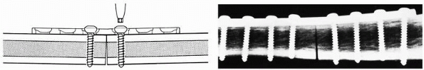
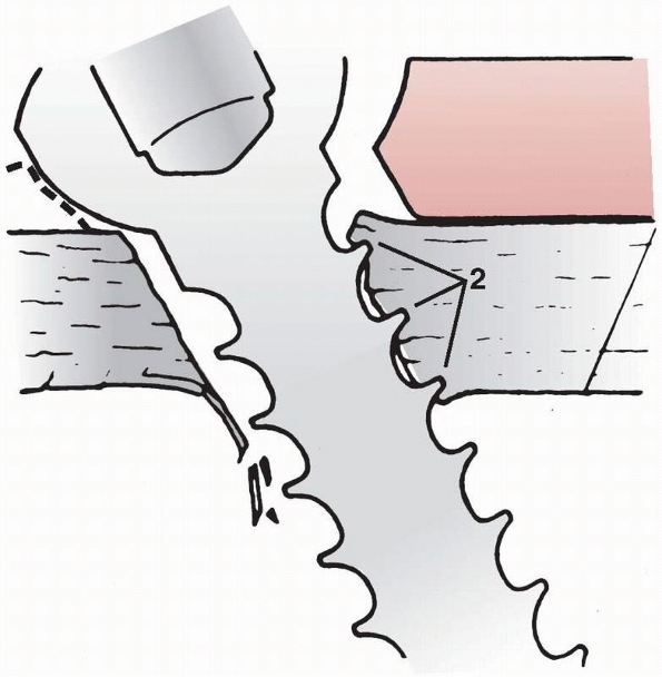
to bending fatigue failure. Observing the cross section of an oval hole
in a dynamic compression fracture plate, Figure 1-32,
shows that one border of the hole actually has an inclined surface.
When the head of the screw displaces downward toward the bone surface,
the screw and the fragment of bone it is attached to slide toward the
center of the plate. This action, which occurs in both fracture
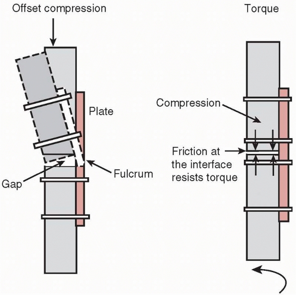
components, causes the fracture surfaces to be driven together2 and creates significant compressive forces across the ends of the fracture.37
Compressing the ends of the fracture significantly improves the
stability of the construct and reduces bending and torsional stresses
applied to the plate, increasing its life. Stability is improved
because the bone ends resist bending forces that close the fracture
gap, and torsional loads are resisted by the frictional force and
interlock between the ends of the fracture components. Also, the
fracture gap that must be healed is smaller.
 |
|
FIGURE 1-32 A. Cross section through the head of a bone screw and the hole in a fracture plate showing the geometry. B.
As the screw is tightened, the head slides down the inclined border of the plate, which displaces the screw sideways, and therefore the screw and the bone fragment to which the screw is attached are displaced toward the opposite fragment. |
 |
|
FIGURE 1-33 Left:
When a gap is left on the cortex opposite that to which the plate is attached, bending of the plate at the fracture site can cause the plate to fail rapidly in bending. Right: Compressing the fracture surfaces not only allows the bone cortices to resist bending loads but the frictional contact and interdigitation help resist torsion. |
vulnerable to bending failure, because plates are thin, relatively easy
to bend (compared to bone), and have low moments of inertia. They are
designed to apply compressive force to the ends of the fracture, and
the stabilized bone can then resist the bending loads applied during
functional use. If a gap is left on the side opposite the plate, Figure 1-33,
the fracture site becomes a fulcrum around which the plate bends under
combined compressive and bending loads such as those which occur during
ambulation (if the compressive force is not located directly down the
tibial
shaft,
which occurs during heel strike and toe off, then bending loads will be
applied along with the compressive force). Gapping can also occur when
a segment of bone is missing at the fracture site, or if the plate is
not properly contoured during application. Figure 1-34
demonstrates how a flat, noncontoured plate tightened against a flat
bone surface will cause a gap to appear on the opposite cortex.118
This is why a plate should be prebent sufficiently to create an initial
gap between it and the bone surface it will be applied to.68,119,136
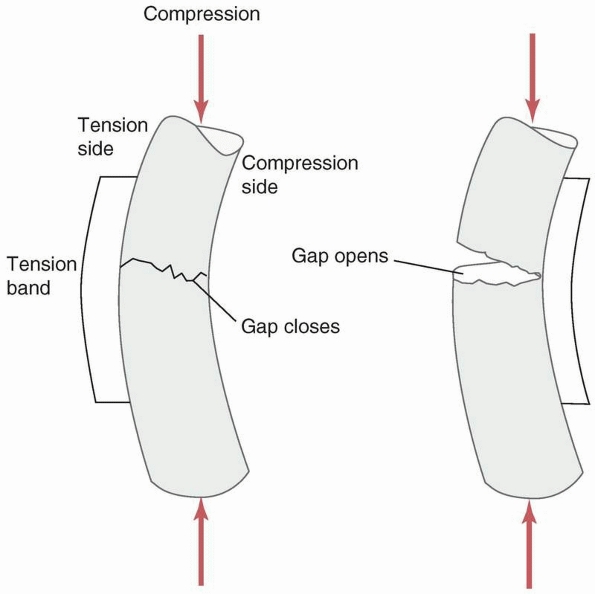
Gapping at the fracture also occurs when the plate is applied to the
predominantly compressive side instead of the tensile side of a long
bone during functional loading that causes bending. Figure 1-35 demonstrates that placing the plate on the compressive side will cause a gap to open under load.
 |
|
FIGURE 1-34
A demonstration of the gapping that occurs on the opposite cortex when a flat plate is applied to a flat bone surface. Slightly prebending the plate causes the ends of the opposite cortices to be driven together when the plate is applied.118 |
In comminuted fractures in which it is difficult to approximate the
fracture ends, screws should be placed as close as possible across the
fracture gap to reduce strains in the plate.53
Torsional and bending stiffness of a fracture construct can be
significantly increased, and therefore plate strain reduced, by
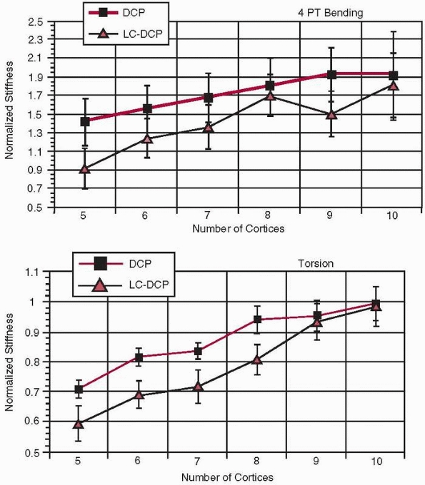
increasing the length of the plate itself133 as well as with several cortices of fixation (i.e., screw-cortex contact). However, as shown in Figure 1-36,
there is an optimum number of cortices, eight for DCP plates and nine
for LC-DCP plates, beyond which there is little additional gain in
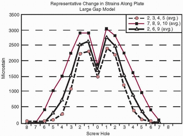
torsional stiffness54. Figure 1-37
shows several interesting aspects related to plate fixation with
screws. First, plate strains are highest at the two holes adjacent to
the fracture gap and become very small five holes away. Second, this
occurs regardless of whether the screws were placed near the fracture
(locations 2, 3, 4, and 5), far from the fracture (locations 7, 8, 9,
and 10), or were mixed (locations 2, 6, and 9).53 This data also indicates that not all holes of the plate need to be filled with screws to provide similar fixation stiffness.
 |
|
FIGURE 1-35
The application of a plate on the compressive as opposed to the tensile side of a bone subjected to bending causes a gap to open on the opposite side of the plate during functional loading. |
in which the screw head has a machine thread, separate from the bone
thread, which locks it to the plate. The screws and plate form a rigid
connection. In addition, the screws have been designed with a finer
thread for unicortical fixation.53
The LISS plate functions differently biomechanically from the dynamic
compression plate (DCP). The DCP plate is compressed against the bone
fragments by the screws and requires bone to plate contact to produce a
stable fracture construct. Buttressing of the opposite cortex is
important in maintaining fracture stability and reducing plate stresses
with the DCP plate. Bending loads applied to the screws in the
nonlocking DCP plate caused the screws to rotate within the plate
resulting in fracture fragment motion, higher plate stresses, and
reduced stability at the fracture site.
in which the pins (screws) are rigidly connected to the side bar (the
plate) and bone to fixator contact is reduced in the low contact plate
version. This produces less interference with the biological processes
of fracture healing, especially helping to preserve the blood supply
near the fracture site. Also, the LISS plate provides more stability in
comminuted fractures142 in which
cortical buttressing and compression are difficult to achieve and
fracture mechanical stability occurs mainly from the hardware.50
LISS plates do not allow the screws to be directed obliquely, except
when specifically designed into the implant, and do not generally
develop interfragmentary compression at the fracture site. Bending
loads applied to the screws from bone are resisted by the locking
interface between the threads in the screw head and the threads in the
plate. Therefore, these plates are not as dependent on cortical
buttressing for stability as the DCP plate. Dynamic fatigue testing has
shown that LISS plates have fatigue strengths similar to other systems
and are able to support loads comparable to 1 bodyweight for 2 million
cycles, which should be sufficient for normal fracture healing. Because
screw
pullout strength is related directly to the length of screw purchase in
bone cortex, the unicortical screws used in some systems have lower
pullout strength than bicortical screws. More screws must be used to
compensate for the inherent lower pullout strength of the unicortical
screw. As with other systems, the LISS plates have mechanical
sensitivities. For example, accurate placement of the locking screws is
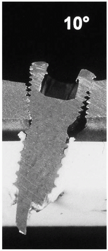
important. As Figure 1-38
shows, angulation of the screw causes incomplete engagement and,
therefore, lower mechanical stability of the construct. In fact,
comparatively, the bending stability of a 4.5-mm LISS plate was reduced
to 63% and 31%, respectively, caused by a 5- or 10-degree misalignment
of the locking screws in the plate.81
 |
|
FIGURE 1-36 Relative stiffness of a plate-bone construct in (top) torsion and (bottom)
bending as a function of the number of cortices through which screws have been placed (DCP, dynamic compression plate, LC-DCP, limited contact dynamic compression plate).54 |
 |
|
FIGURE 1-37 Distribution of strain (measured in microstrain or strain × 10-6)
at various locations along a plate regardless of placement of the screws in different locations (holes 2, 3, 45), (holes 7, 8, 9, 10), or holes (2, 6, 9).53 |
 |
|
FIGURE 1-38 A demonstration of the importance of accurate placement of locking screws into the plate.81
|
provide flexibility of fixation of bone fractures with complex
geometries. It is not necessary to place screws in every hole in the
plate,46 but the effects of screw
placement on fixation stiffness should be understood. The screw hole
will be an area of elevated stresses on the plate, unless the plate is
made thicker near the holes to compensate, as is the case with some
plates. Placing the plate so that an empty screw hole is located over
the fracture will significantly increase the potential for fatigue
fracture of the plate. The plate material around the holes will have
higher material stresses than occurs in the solid regions of the plate.
Around the holes, the force acts through a smaller cross-sectional
area, so the material stresses must be higher. A second consideration
related to multihole plates is that separating the screws so that there
is a greater distance between them across the fracture site results in
lower stiffness of the plate-fracture construct. As with any beam
(plate), the greater the distance between the supports (screws), the
greater the bending displacement and the higher the stresses will be
for the same applied load. It is best to avoid placing screw holes over
or near the fracture site and it is beneficial, in terms of improving
fixation stiffness, to place screws as close together across the
fracture site as possible.
large compressive forces across fracture fragments, and these forces
are applied directly across the fracture site. The head and upper part
of the shaft of the screw must be allowed to glide in one fracture
component so that it pulls the other fracture component towards it to
create compression across the two. As shown in Figure 1-39,
a fully threaded lag screw blocks the gliding action between the two
components. Comparing the compressive forces across the fracture site
using fully and partly threaded lag screws demonstrated that the
average compressive force at the opposite cortex (i.e., the force in
the screw itself) was about 50% greater when a partly threaded screw
was used.86
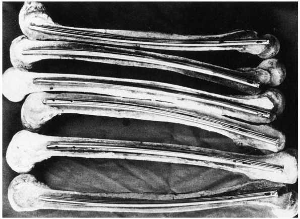
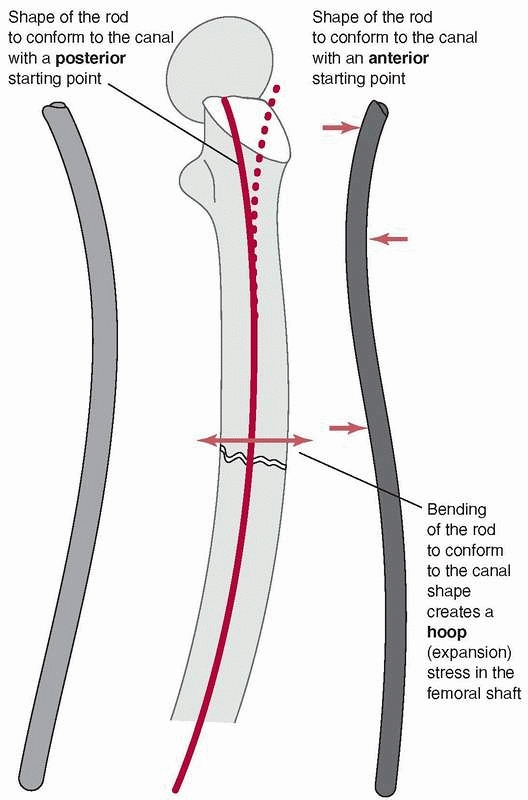
can lead to difficulties because the femur has a significant anterior
curvature,169 shown in Figure 1-40.
Current femoral nails have radii of curvature that range from 186 to
300 cm, compared with the average for a large sample of femora, which
was 120 +/- 36 cm. Therefore, current femoral nails are considerably
straighter than the femora they are inserted into.49
The rod, which also has a curved shape to accommodate the femoral bow,
must conform to the curvature of the femur as insertion progresses.
Placing a rod, which is essentially a steel curved spring, down the
femoral canal causes the rod to bend, because the femur is generally
much stiffer than the rod, Figure 1-41. In fact, the nail must conform not only to an anterior-posterior
bow but also canal curvature medially and laterally.51 Figure 1-42
demonstrates that rod contact with the internal surfaces of the femur
generates forces which resist insertion. These rodfemur contact forces,
directed perpendicular to the surface of the medullary canal cause the
femur to expand and will result in splitting if they become too large.80
 |
|
FIGURE 1-39
Using a fully threaded lag screw causes the threads to engage in bone on both sides of the fracture. This inhibits the screw from compressing the bone fragments together.86 |
 |
|
FIGURE 1-40 Cross sections of various femora demonstrate the curvature that an IM rod must conform to when it is fully inserted.169
|
 |
|
FIGURE 1-41
Mismatch of the curvature between the IM rod and the medullary canal results in bending stresses that could cause splitting of the femur during insertion.80 |
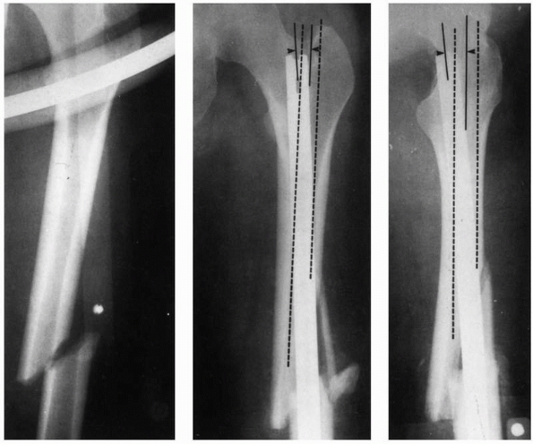
during insertion and the resulting internal forces acting within the
femur are the proximal starting hole position, the length of the
proximal fragment, the initial curvature of the IM rod compared with
the curvature of the femur, and the rod bending stiffness. Stiffnesses
of rods can vary considerably.131 Figure 1-42 demonstrates examples in which rod proximal starting hole position resulted in femoral splitting during rod insertion.80 Some newer IM nails employ a valgus bend to be used with a femoral trochanteric entry portal.120
The optimal entry point for retrograde nailing, used selectively when
antegrade nailing is not possible, was found to be about 1.2 cm
anterior to the femoral origin of the posterior cruciate ligament and
at the midpoint of the intracondylar sulcus.91
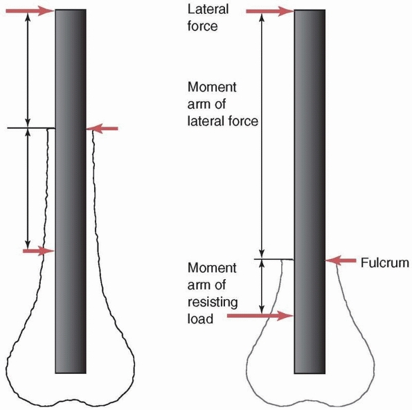
occasionally during healing. The most demanding mechanical situation
for IM rod fixation of the femur or tibia occurs when the fracture is
very distal. Figure 1-43 compares the forces
acting on idealized femora with more proximal and more distal
fractures. For a specific location of the external load (muscle load or
body weight), the more distal fracture results in a longer moment arm
(the perpendicular distance from the load to the fracture site)
creating a greater moment, and therefore higher stresses in the rod.
The highest stresses in the rod occur near the fracture site. With a
distal fracture, in addition to the greater moment, the locking
holes—which are significant stress risers—are usually located just
distal to the fracture site. It has been shown that the maximum
stresses acting in the rod increase rapidly once the distance between
the fracture and the most superior of the distal screw holes is reduced
to less than about 4 cm.28 Cyclic
loading of nails used to fixed distal fractures, with peak loading of
about 1 times bodyweight, confirm that titanium alloy nails can survive
more than 1 million loading cycles when the more proximal of the distal
locking screws is more than 3 cm from the fracture site.7
In addition, placing the distal locking screws can be difficult because
they must be inserted freehand under fluoroscopic guidance. Sometimes
the corner of the screw hole of the rod can be nicked by the drill or
while driving the screw, creating an additional stress riser that can
accentuate the fatigue process. Awareness of these potential problems
has led to design changes such as closing the proximal section of the
rod, increasing material thickness around the screw holes, and cold
forming, which increases the strength of the rod material.
screws are placed into bone with relatively low bone density, the screw
is supported mostly by the cortices. The distal end of the femur widens
rapidly (Fig. 1-44), so the unsupported length
of the screw between the cortices can be quite variable. For the same
diameter and material, the stiffness and strength of a screw subjected
to bending decreases with the third power of its unsupported length
(the distance between cortices, assuming no support from the trabecular
bone). If the unsupported length of one screw is twice as long as that
of another, and assuming that the trabecular bone does not contribute
to support of the screw, one can expect the stiffness and strength of
the screw with the longer unsupported length to be 8 times less than
that of the screw with the shorter length between cortical supports,
and therefore the deformation will be 8 times greater under the same
load. This does create a tradeoff in fixation of
these
fractures with respect to screw placement. If the screws are too close
to the fracture, the stresses in the rod increase, while if they are
located within the flair of the metaphysis, with poor trabecular bone,
their unsupported length increases, decreasing stiffness and strength.
The fatigue life of the distal locking screws is directly related to
the diameter of the root of the thread and the resulting moment of
inertia, so it has been proposed to remove the threads to increase
fatigue life by 10 to 100 times.73
 |
|
FIGURE 1-42
The starting position selected for rod entry into the medullary canal affects the degree to which it must bend and the internal forces generated in the femur. A starting position offset from the axis of the medullary canal, coupled with a stiff rod and a longer proximal segment that requires the rod to bend more during insertion, generate higher insertion forces and internal femoral forces. In this example of a midshaft femoral fracture (left), the starting hole was selected medial relative to the axis of the medullary canal (middle) and posterior (right). The medullary canal is outlined in dashed lines. Therefore the rod must bend both medially and posteriorly as it is inserted into the canal and has created internal stresses which have split the distal end of the femur.80 |
 |
|
FIGURE 1-43 If the same force acts on IM rods placed in femora with more proximal (left) or more distal (right)
fractures, the moment arm of the force will be longer in the case of the more distal fracture and therefore the moment acting at the fracture site on the implant will be larger. For the more distal fracture, the high stress region close to the fracture site is also significantly closer to the distal locking screw holes which are significant stress risers. |
from several causes. The shape of the end of the pin itself, because it
is self-tapping, can affect the local heat generated in bone during
insertion, potentially causing thermal necrosis around the pin hole
site,160 along with bone microcracking. In addition, high
local stresses can occur in the pins and bone if the hole through which the pin is inserted is undersized.78 A third mechanism, Figure 1-45,
is micromotion, which induces bone resorption at the pin/bone interface
if the pin is a loose fit in the hole. To reduce these problems, slight
undersizing of the bone hole by about 0.1 mm in diameter has been
advocated. If the bone hole is undersized by 0.3 mm in diameter, the
yield strength of bone may be exceeded when the pin is inserted.118
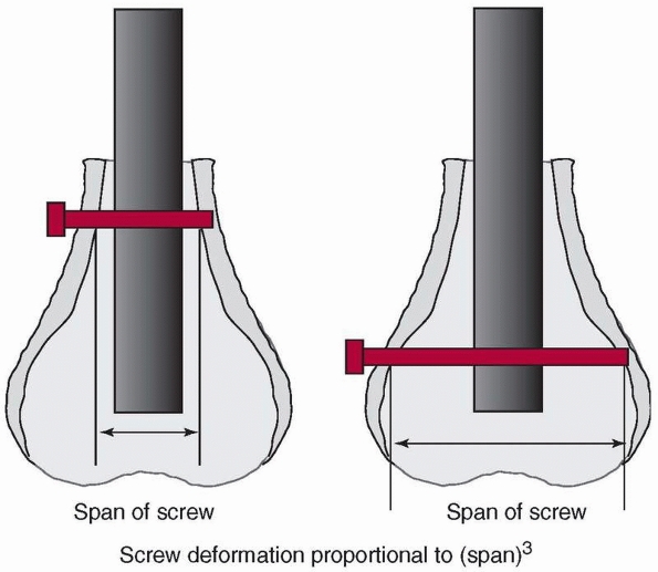 |
|
FIGURE 1-44
Because the distal end of the femur flares rapidly, the length of the locking screw required to crosslock the rod can be quite variable. If the screw is not well supported by trabecular bone but mainly by cortex, then its stiffness and strength decrease with the 3rd power of its length between cortices. If the screw length doubles, the deformation of the screw under the same load increases by a factor of 8. |
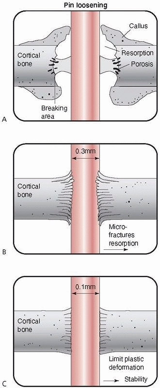 |
|
FIGURE 1-45
A proposed mechanism for loosening of external fixation pins involves under- or oversizing the diameter of the pin relative to the bone hole. A. If the pin and bone hole are the same diameter, micromotion can occur with bone resorption. B. If the pin is more than 0.3 mm smaller in diameter than the hole in bone, microfracture may occur during insertion. C. If the bone hole diameter is about 0.1 mm smaller than the pin diameter, the bone is prestressed but does not fracture, micromotion is eliminated, and pin stability is maintained.118 |
bone fragments, along with clamps and sidebars that couple the pins.
This assembly allows considerable variation in construction of a frame
to accommodate the fracture. The optimal stiffness of a fixator is not
specifically known. The stiffness necessary to stabilize the fracture
and induce healing changes as the fracture consolidates. It must be
rigid enough to initially support the forces applied by the patient
during ambulation without causing malalignment of the fracture. On the
other hand, it should not be so stiff that the fracture is shielded
from the stresses required to stimulate healing. Some basic mechanical
guidelines in the construction of the frame, explained below, will
ensure that frames are adequately constructed for the loads they are
subjected to. Figure 1-46 demonstrates that
when the diameter of a pin or sidebar increases, its stiffness and
strength increase to the 4th power of the relative change in diameter
(actually the ratio of the larger to the smaller diameter). As its
length (distance between bone surface and sidebar) decreases, stiffness
and strength increase to the 3rd power of the length change. This
principle also holds also for the pins spanning the fracture, which
affect the unsupported length of the sidebar across the fracture.
the sidebar to bone distance, which decreases the unsupported lengths
of the pins, increases the pin diameter, and decreases the distance
between the pins which span the fracture—for example, increasing the
number of pins applied also increases frame stiffness. In terms of
actual effects, for example in bending, doubling the sidebar distance
from bone decreases frame stiffness by about 67%, doubling the
separation distance of the pins across the fracture decreases stiffness
by 50%, and decreasing pin diameter by 1 mm (from 6 to 5 mm, for
example) also decreases frame stiffness by about 50%.152
Using a partly threaded pin and burying the pin thread completely
within the cortex enhances the stiffness of the pin, because the
smaller diameter of the root of the pin thread is not exposed. Also,
using hydroxyapatite coated external fixation pins to enhance the
screw-bone interface117 can be a good option.
are constructed to resist the major loads, axial compression, and
anterior-posterior bending, acting on a long bone such as the tibia
during walking, with the sidebar usually aligned with the
anterior-posterior plane. To resist torsion and out-of-plane
(medial-lateral) bending, the fixator can be assembled with additional
pins and sidebars in other planes. A comparison of the relative
stiffnesses of different fixator assemblies is given in Figure 1-47.
The unilateral half pin frame with sidebars mounted at right angles
provides the greatest overall resistance to bending, compression, and
torsional loads.20 Hybrid fixation
devices have adopted components of both unilateral bar fixators and
ring fixators with wire transfixing pins. Both axial compression and
torsional stiffnesses have been found to increase significantly with
increases in the number and diameter of the transfixing wires, and
pretensioning the wires.31 More
anterior placement of wires, or addition of an anteromedial halfpin
have been found to increase anterior-posterior bending stiffness.63 Testing of several different configurations (see Figure 1-48)
showed that the box type (two rings above and two below the fracture,
along with anterior half pins, two connecting rods and a unilateral
bar) was the stiffest configuration, compared with a unilateral frame
alone or a unilateral frame with rings only proximal to the fracture
site. The addition of an anterior half pin significantly increased
fixation stiffness.128
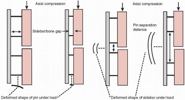 |
|
FIGURE 1-46
To produce more rigidity in construction of an external fixator, the basic principles that should be considered are that for pin and rod type sidebars, stiffness increases with the 4th power of the cross-sectional area (the moment of inertia, Fig. 1-7) and decreases with the 3rd power of their span or unsupported length (Fig. 1-44). This explains why it is beneficial to decrease sidebar to bone distance, increase pin diameter, place pins as close together across the fracture site, and use larger diameter or multiple sidebars in frame construction.77,152 |
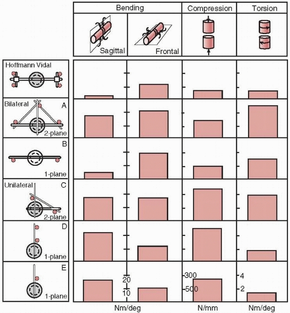 |
|
FIGURE 1-47
A comparison of the bending, compression, and torsional stiffnesses of different external fixation constructs for multiplane load resistance.20 |
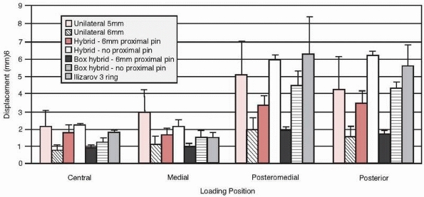 |
|
FIGURE 1-48
A comparison of displacement of the proximal fragment in a simulated tibia fracture under 100N load with various unilateral and hybrid external fixators (the box type uses both a large unilateral frame connecting bar and two smaller diameter connecting rods).128 |
bone, a screw for example, is directly related to the local bone
density, and because a dominant mechanical characteristic of
osteoporotic bone is low density, several strategies can be used when
osteoporotic bone is encountered. These include cortical buttressing by
impaction; wide buttressing, which spreads the load over a larger
surface area; long splintage; improved anchoring; and increasing the
local bone density by injection of, for example, hydroyapatite or
methylmethacrylate, see Figure 1-49.71
Impaction strategies can be applied in fractures of the distal radius,
femoral neck, and lumbar vertebrae. The dynamic hip screw is an example
of a device which allows controlled impaction of the fracture of the
femoral neck. An angled blade plate applied to supracondylar femur
fractures, as compared with a condylar screw, provides wider
buttressing—that is, a larger surface area of contact with bone. The
rafter plate, which permits placement of numerous cancellous screws for
tibial plateau fractures, is another example of the application of this
principle.25 Long splinting with a
longer, more flexible plate has been applied in humerus fractures, and
the interlocked intramedullary rod is a second example of long
splinting. Enhanced anchoring of pedicle screws using augmenting
laminar hooks is an example of augmentation of anchoring.17
The locking plate, in which the screws are threaded into the plate and
fixed so they cannot rotate, can be useful in stabilizing osteoporotic
fractures when cortical buttressing is not practical because of low
bone density and the fixation hardware must support most of the load.
Hydroxyapatite coated external fixation pins have been shown to enhance
the screw-bone interface.117 Interlocking
screws, in which a standard screw has a 45-degree hole drilled into the
shaft to accept an interlocking pin, can be used to reduce screw
backout.107
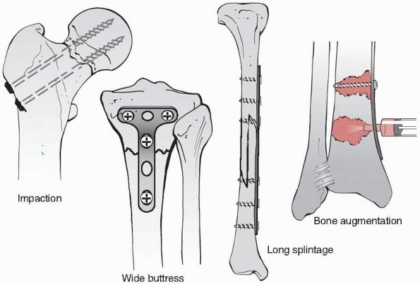 |
|
FIGURE 1-49
Some basic strategies to augment fixation strength in osteoporotic bone include impaction of the fracture components using a device that allows sliding, buttressing with a wide plate, increasing the plate length, and augmenting the bone locally by injection of methylmethacrylate or a calcium phosphate cement.71 |
more recently, absorbable hydroxyapatite cements has been studied,
particularly in relation to fixation of femoral and vertebral
osteoporotic fractures. PMMA injection has been widely employed in
vertebroplasty through a transpedicular approach99
and has been shown to restore the stiffness of fractured vertebrae to
that of intact vertebrae. Biomechanical studies have shown
significantly improved strength of the fixation of femoral neck
fractures, up to 170%,147 and
similar findings, including decreased shortening and greater stability
were noted when hydroxyapatite cement was applied to unstable
three-part intertrochanteric fractures fixed with a dynamic hip screw.52
Calcium phosphate cements used in vertebroplasty instead of PMMA also
restored the stiffness of fractured vertebrae to intact levels.102
Calcium phosphate cement injection into the pedicle has been shown to
improve the bending stiffness of pedicle screws by up to 125%.18
screw pullout and plate breakage common to fracture fixation mainly in
the long bones were discussed. In this section, the focus is placed on
specific challenging problems in fixation, including the femoral neck,
tibial plateau, pelvis, and spine.
particularly challenging because the compressive force acting through
the femoral head can range from 4 to 8 times body weight during normal
activities.121 This force acts
through a significant moment arm (the length of the femoral neck),
which causes large bending loads on the fixation hardware. In addition,
many of these fractures occur in the elderly, who are likely to have
trabecular bone of low density and poor mechanical quality.100 Also, it is generally not possible to gain screw purchase in the cortical bone of the femoral head.
fracture of the femoral neck, fixed with a sliding hip screw is the
joint reaction force through the femoral head, which derives from body
weight and forces generated by muscle action during ambulation. The
joint reaction force can be divided into two components. One (Fig. 1-50)
is perpendicular to the axis of the sliding screw and causes shearing
of the fracture surfaces along the fracture line, which results in
inferior displacement and varus angulation of the femoral head, and
increases the resistance of the screw to sliding. The other is parallel
to the screw, driving the surfaces together and enhancing stability by
frictional and mechanical interlocking of the fracture. Therefore, the
aim of femoral neck fixation systems is to utilize the component of the
joint force parallel to the femoral neck to encourage the fracture
surfaces to slide together. This is the basic principle behind
selection of a higher angle hip screw when possible.
nail with a sliding lag screw, it is important to ensure that the screw
can slide freely in the barrel of the side plate or the hole in the
nail. The following comments related to sliding hip screw devices apply
as well to nail/lag screw constructs. When screw sliding occurs, the
screw is supported by the barrel against inferior bending of the
femoral head because the construct is buttressed by fracture
interdigitation. Adherence to two basic mechanical principles will
enhance the ability of the screw to slide in the bore of the side plate
or nail. As mentioned above, the higher angle hip screw is more
effective at accommodating sliding. Also, the screw should be engaged
as deeply as possible within the barrel. For the same force acting at
the femoral end of the screw, the internal force where the screw
contacts the barrel is increased if less of the screw shaft remains in
the barrel. This occurs because the moment (bending load) caused by the
force transverse to the axis of the screw (Fh in Fig. 1-51)
(at the femoral head) acts over a longer moment arm or perpendicular
distance, Le (force X perpendicular distance to the edge of the barrel,
which is the fulcrum). The balancing moment arm, Lb, is shorter because
less of the screw remains in the barrel. Because Fh acts over a longer
moment arm while Fe acts over a shorter moment arm, Fb increases. The
internal force, Fb, where the screw contacts the barrel causes a
greater frictional resistance force, which requires more force to
overcome to permit sliding.93
Sliding hip screws with either two- or four-hole side plates appear to
provide equivalent resistance to physiologic compressive loading.110
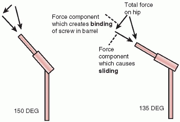 |
|
FIGURE 1-50
The joint reaction force in the femoral head can be divided into two major components. The one parallel of the axis of the femoral neck produces sliding and impaction of the fracture components and the other, transverse to the femoral neck, causes the screw component of the femoral hip screw to bind, resisting sliding. The higher-angle hip screw has a screw axis more closely aligned with the joint reaction force so the force component that produces sliding is larger while the transverse force component resisting sliding is smaller. |
fixation using multiple screws, but the number of screws used (three or
four) is not a significant factor.155
Factors that do increase the strength of this type of fixation include
a more horizontal fracture line with respect to the long axes of the
screws,48 placement of the screws in areas of greater femoral head bone density,145,149 fractures with less comminution129 and a shorter moment arm for the joint load (shorter distance from the center of the femoral head to the fracture line).145
However, the most important factor has been found to be the quality of
the reduction because of the importance of cortical buttressing in
reducing fracture displacement.143 Under physiological load, several mechanisms of failure of fixation have been observed, see Figure 1-52.
In some cases the screws bend inferiorly, especially if buttressing of
the fracture surfaces inferior to the screws is not possible because of
comminution of the fracture. The fixation screw heads, if no washers
are used to distribute the screw load against bone, have been found to
pull through cortex near the greater trochanter when the cortex is
thin. Finally, if the screws are not well supported inferiorly where
they cross the fracture, they may rotate inferiorly carrying the
femoral head into a varus orientation.145 Supporting at least one screw against the inferior cortex may help prevent this from occurring.
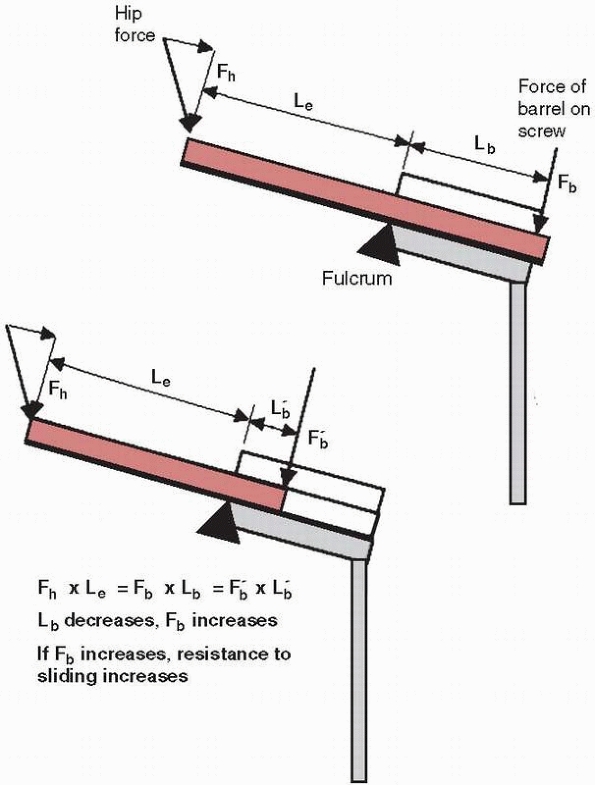 |
|
FIGURE 1-51
The greater the length of the sliding screw within the barrel, the lower its resistance to sliding. In this diagram Fh is the component of the joint reaction force perpendicular to the axis of the screw. The inferior edge of the proximal end of the barrel is the location of the fulcrum in bending. An internal force, Fb, from the surface of the barrel acts against the screw to counteract Fh. For equilibrium, the moments produced by Fh (Fh × Le) and Fb (Fb × Lb) must be equal. If Lb, the distance from the point of application of internal force Fb to the fulcrum, decreases, Fb must increase to produce the same moment. If Fb is larger, the frictional force and therefore the resistance to screw sliding will increase. (Le is the length of the screw beyond the barrel).93 |
different devices, the actual stiffness provided by the sliding hip
screw, the reconstruction nail, and multiple pin constructs are quite
similar, except that the reconstruction nail offers significantly
greater torsional stiffness than the other forms of fixation because of
its tubular shape.66,130
New techniques applied to proximal fracture fixation include the
femoral locking plate and percutaneous compression plating. In fixation
of the challenging vertical shear fracture of the proximal femur, the
proximal femoral locking plate was found to produce considerably
stiffer constructs than cannulated screws, a dynamic hip screw, or a
dynamic condylar screw.6 Percutaneous compression plating has been found to provide adequate bending and torsional stability92
and was equivalent to the trochanteric antegrade nail in fracture site
stability, though it failed at about 2100N (about 3 times body weight)
compared to the antegrade nail at 3200N.67
are challenging to stabilize because they may involve fixation of
multiple small fragments of primarily cancellous bone. Supracondylar
fixation alternatives that have been compared mechanically include
condylar plates, plates with lag screws across the fracture site, and
blade plates. All devices tested appeared to provide similar construct
stiffnesses. The most important factor identified for plate fixation
was maintaining contact at the cortex opposite that to which the
fixation device was applied. Fixation constructs without cortical
contact were only about 20% as stiff as those with cortical buttressing.59,140
Using a retrograde intramedullary supracondylar nail was found to
produce constructs that were 14% less stiff in axial compression and
17% less stiff in torsion, compared with a fixed angle side plate.112 However, longer nails (36 cm) enhanced fixation stability compared to shorter nails (20 cm).144
Several newer fixation systems have been described for femoral
supracondylar fracture stabilization. The less invasive stabilization
system (LISS) uses a low-profile plate with monocortical screws
distally which also lock to the plate. LISS plates produced constructs
with more elastic deformation and less subsidence than those with a
condylar screw or buttress plate.105,156
Considering patient outcomes, the loss of reduction was related to
patients being more than 60 years old, premature weight bearing,
fracture fragmentation, and severe osteoporosis.4 Different methods of fixation include using wires or screws alone, Figure 1-53,
or screws placed through an L- or T-shaped plate, which buttresses the
cortex. Various configurations of wires have been tested24 and show that the stiffness of the construct increases with the number of wires, regardless of their specific orientations. As Figure 1-53 shows, fixation with screws alone requires
that the screw resist bending forces as the tibial fragment is loaded
distally in compression through the joint. With the addition of a
plate, not only is the load distributed to the plate, but additional
screws can be placed in the stronger cortical bone distal to the
metaphyseal region of the tibia. One disadvantage of a buttress plate
is the additional invasiveness that it requires for installation with
potential compromise of blood supply. Fixation with T plates and screws
showed the greatest resistance to an axial compressive load,46 regardless of the specific configuration of the screws.84
Investigations of different plate configurations found that for
bicondylar tibial plateau fractures, dual (lateral and medial) side
plating reduced subsidence under axial loading by about 50% compared
with single-sided lateral locking plating.72
For medial plateau fractures, the medial buttress plate, which supports
the load directly, is superior mechanically to a lateral locked plate.126
A new alternative is the short proximal tibial nail with multiple
interlocking screws. In combined axial loading, bending and rotation,
the nail provided stability equivalent to that of double plating and
was greater than constructs with a locking plate, external fixator, or
conventional unreamed tibial nail.69
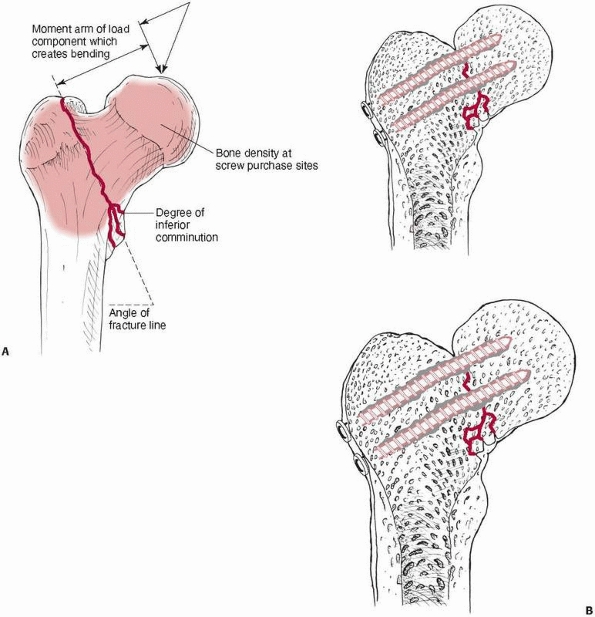 |
|
FIGURE 1-52 A.
Some factors that decrease the strength of femoral neck fracture fixation include decreased bone density; a more vertical fracture surface, which facilitates sliding of the fracture components; comminution at the inferior cortex, which reduces buttressing against bending; and a longer moment arm or distance of the center of the femoral head to the fracture line. B. Observed mechanisms of failure of femoral neck fixation using screws include bending of the pins, displacement of the screw heads through the thin cortex of the greater trochanter, especially if washers are not used, and rotation of the screws inferiorly through the low density cancellous bone of the Ward triangle area until they settle against the inferior cortex.145 |
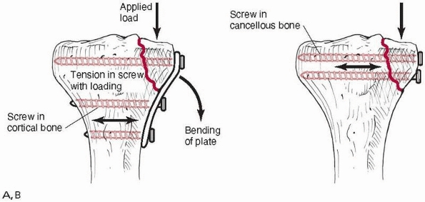 |
|
FIGURE 1-53 Two alternative methods of fixation of tibial plateau fractures: (A) transverse screws combined with a buttress plate and (B)
transverse screws alone. The buttress plate provides additional support in bending as the tibial fracture component is loaded in an inferior direction and allows the screws to engage the thicker, more distal cortical bone. |
cervical spine injuries that are stable in compression. It stabilizes
the injured cervical spine mainly in bending but not in compression.
Factors that affect its mechanical performance include (Fig. 1-54)
the fit of the jacket on the torso and the frictional characteristics
of the lining. High friction linings decrease slip at the vest
lining/torso interface, more rigid vests reduce deflection under loads,
and less flexible superstructures all decrease cervical spine motion at
the injury level. While stiffening the vest enhances its ability to
stabilize the injury, this property must be balanced with enough
flexibility to provide reasonable comfort for the wearer and to
accommodate expansion and contraction of the chest. Because the injured
cervical segment is relatively distant from the vest, small motions of
the vest can result in relatively large displacements at the injury
site.114 A very rigid halo
superstructure attaching the vest to the halo ring may not increase
injury stability if connected to a poorly fitting vest.
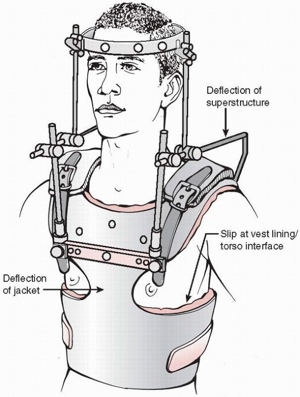 |
|
FIGURE 1-54
A schematic diagram showing possible sources of deformation in the halo apparatus. The large distance from the vest to chest contact points to the cervical injury site results in relatively large motions at the injury site for small motions of the vest.114 |
spine injuries. The major differences between them relate to the
location of the fixation device itself on the vertebra—anterior,
lateral, or posterior—and to the method by which the fixation is
attached to bone. Generally the most rigid fixation is the one with the
longest moment arm from the center of rotation of the injured segment.
For a specific applied moment, say flexion, a posteriorly located
fixation, being located further from the center of rotation, results in
greater rigidity. Figure 1-55 shows the
approximate locations of the centers of rotation at different cervical
spine levels when the posterior elements have been
disrupted.5
After corpectomy, testing has shown that posterior rods provide the
greatest stability, which is unchanged after augmentation with an
anterior plate, while anterior plating alone offers the least stability.146
Similarly, another test showed that after corpectomy, sagittal plane
motion was most rigid after supplementation with lateral mass plates,
less rigid with an anterior plate alone, and least with strut grafting
alone.85 Anterior plates provide
relatively similar stability, especially if augmented with a bone
graft, however, with multilevel corpectomy, anterior plate constructs
were more prone to fatigue loosening than single level corpectomies.79
Some of the newer semiconstrained anterior plates, most of which offer
devices to lock the screws to prevent backout, allow screw rotation
which results in more load sharing with the graft.125
By comparison, the compressive load estimated to be transmitted through
the graft increased from about 40% with a fully constrained device to
about 80% when a semiconstrained device was used.125
Wiring or plating with lateral mass screws generally reduces
anterior-posterior motion across the fixed segment by 20% to 70%, so
none of the techniques can be considered as entirely rigid.113
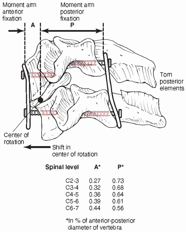 |
|
FIGURE 1-55
The ratios, in terms of anterior-posterior diameter of the vertebra, of the location of the center of rotation at each vertebral level, from the anterior and posterior surfaces. A fixation device must resist bending moments caused by flexion, extension, lateral bending, and torsion. The resisting moment in the fixation is the product of the force acting in the fixation (for example, at the screw-plate junction) and the distance of that point on the fixation to the center of rotation of the motion segment. The longer the moment arm for the same bending load, the smaller the force on the fixation components. Posterior fixation, by its location, will have lower moments in its components.5 |
vertebra is fundamental to its performance. Wires, hooks, screws, or
combinations of them all produce different types of force transfer
between the fixation and the vertebra, Figure 1-56.36
A wire can resist only tension, while a screw can resist forces in all
directions (tension, compression, bending transverse to the axis of the
screw) except for rotation about its longitudinal axis. A hook only
resists forces that drive the surface of the hook against bone, and
depends also on the shape of the hook and the bone surface it rests
against. For this reason, screws are biomechanically superior to other
forms of vertebral attachments.
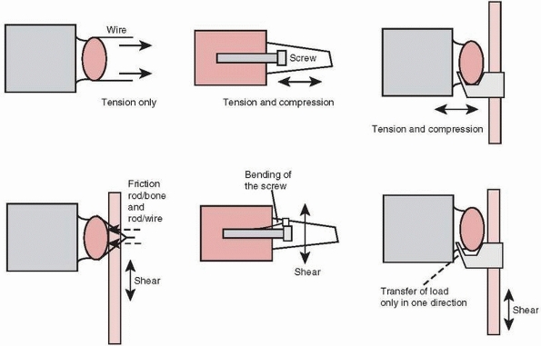 |
|
FIGURE 1-56
Comparisons of the forces that can be resisted by different methods of attachment of the fixation to the vertebra. A sublaminar wire resists only tension, while a screw can resist forces in all directions except for rotation about its long axis. A hook resists only forces that drive it against the bone surfaces. |
manner as bone screws described elsewhere, therefore pullout strength
increases with increased density of the bone it is embedded into,33,104,161,164 a greater depth of insertion,95 engagement of the anterior cortex,115
and a larger screw diameter. Single screws placed into pedicles and
loaded in a caudal-cephalad direction, which occurs during flexion and
extension of the vertebra, are vulnerable to toggling, and eventual
loosening, even under relatively small forces. As demonstrated in Figure 1-57,
the screw tends to toggle about the base of the pedicle, which is the
stiffest region, being comprised mainly of cortical bone. Toggling
tends to open the screw hole in a “windshield wiper” fashion.13,95
Toggling can be reduced if the screw head is locked to the plate or
rod, and the plate or rod contacts the vertebra over a wide area.95
applying lumbar spinal fixation. Longer fixation, attached to more
vertebrae, reduces forces acting on the screws because of the effect of
the greater lever arm of a longer plate or rod. A longer fusion,
although biomechanically advantageous, is not necessarily beneficial
from a clinical perspective because remaining spinal motion is
significantly reduced. Adding an anterior strut graft or a fusion cage
is important because it buttresses a posterior fixation system against
flexion moments, reducing forces in the fixation.89
Coupler bars, which connect the fixation rods to form an H
configuration, prevent the rods from rotating medial and lateral when
torsion is applied to the motion segment, Figure 1-58. This significantly enhances the torsional and lateral bending stability of the implant.72
to be developed. Testing of anterior fixation systems with and without
an augmented strut graft showed that load sharing with the graft ranged
from 63% to 89% for six systems tested, three being plates and three
based on locked rods. These tests demonstrated the significant effect
of the graft in sagittal plane stability of the fixation. The most
rigid systems, not significantly different in performance, relied on
either a thick rigid plate or large rods.26
In cases of delayed or nonunion the cyclic performance of the implant
can be very important, more so than its static stiffness or maximum
load to failure. A comparison test of 12 fixation systems showed that
only three could withstand 2 million load cycles with 600N of
compressive force. The two fixations with greatest bending strength
also did not fail after cycling, however, there was no correlation
between bending strength and cyclic failure for the other 10 systems,
indicating that particular design aspects could cause fatigue failure
regardless of static strength.88
Three devices failed in less than 10,000 cycles. Currently, most
posterior devices use essentially the same principles, including
pedicle screws with an interface clamp to the rod that allows variable
orientation of the screw, a low profile assembly, and crosslinks. They
provide similar fixation stiffness. Lumbosacral fixation using sacral
screws was most rigid and demonstrated the least screw strain when
supplemented with iliac screws, and was more effective than using
screws at S1 supplemented with screws at S2.96
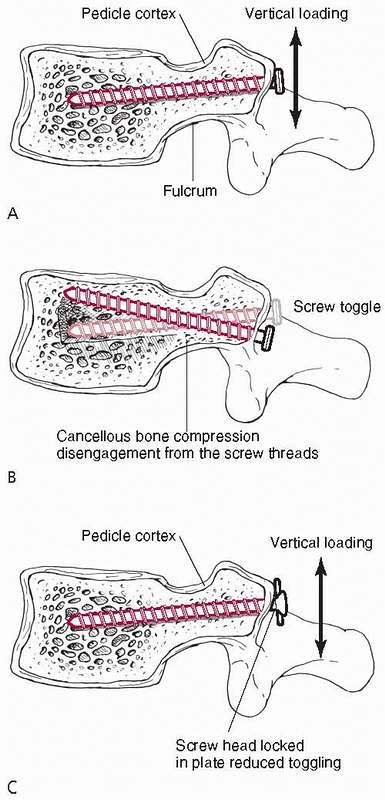 |
|
FIGURE 1-57 A. The mechanism of toggling of a single pedicle screw subjected to a caudo-cephalad loading. B.
The fulcrum is at the base of the pedicle, the narrowest region with little cancellous bone. The screw toggle compresses bone within the vertebral body. C. Toggling is reduced if the plate or rod to which the screw connects contacts the vertebra over a wide surface, which prevents it from rotating, while the screw head is locked to the plate or rod.95 |
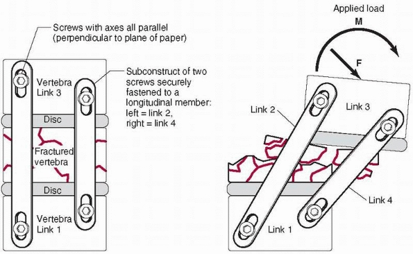 |
|
FIGURE 1-58 Without a coupler bar between two longitudinal rods (left), they can rotate when a lateral moment or axial torsion is applied (right). A coupler connecting the rods to form an H configuration reduces this effect.72
|
investigated. A fusion cage is a hollow threaded insert that can be
applied from anterior, lateral, or posterior directions in single or
double units. Various fusion cages are available for the cervical
spine. The devices fall into one of three categories: screw designs
with a horizontal cylinder and external threads, box shapes, and
vertical cylinders. In general, all cage designs increased flexion
stiffness by 130% to 180%. Only a few box or cylinder designs increased
extension stiffness, and box designs were most effective in increasing
axial rotation and lateral bending stiffnesses, ranging from 140% to
180% of intact values.82 Testing of
lumbar fusion cages has shown that placement of cages in lateral,
posterolateral, or posterior orientations had little effect on
stiffness, except for torsional loading with posterior cage placement,
because posterior insertion damaged the lamina
or
facets, reducing the inherent torsional stability of the motion
segment. Fixation with cages alone did not significantly increase
lumbar motion segment stability, so augmentation with posterior
fixation in cases of motion segment instability is necessary. Because
cage fixation relies on the combination of distraction of the soft
tissues and the strength of the vertebral cancellous bone, the
properties of these tissues will have a significant effect on the
performance of cage implant constructs.153
provided greater stability against torsional loading but were similar
to blade plate constructs in bending, because both fixation devices are
loaded as tension bands in bending.116,137,138
In comparing different types of blade plate constructs, the stiffest
construct employed an eight-hole, low-contact dynamic compression
plate, contoured into a blade configuration, and fixed with a diagonal
screw that triangulates with the end of the blade. This arrangement was
considerably stiffer than other blade plates or T plate and screw
constructs.101 One potential problem is penetration of the screws through the subchondral bone in osteoporotic patients.
appreciation of the forces applied to a damaged bone or joint and the
basic mechanisms by which these loads are transferred through the
bridging fixation and the implant-bone interface. In particular, the
importance of the contribution of cortex-to-cortex contact across the
fracture site in resisting both compressive and bending forces must be
emphasized. This contact creates a buttress that contributes
significantly to the stability of the construct and the functional life
of the implant. Many of the observations used to formulate these basic
principles have been made using cadaveric bone in experimental
laboratory simulations, and conclusions are based on comparisons of the
most rigid mechanical construct. Other aspects such as the compromise
of blood flow or the extent of the incision during installation should
also be considered. Further, even if one construct is more rigid than
another, within a certain range of mechanical stiffness, both may
perform equally well in producing fracture healing with anatomic
alignment. It is important to correlate the biomechanical findings to
clinical observations of the performance of the implant during fracture
healing.
GB, Dennis MG, Elshinawy A, et al. Circumstances of falls causing hip
fractures in the elderly. Clin Orthop Rel Res 1998;348:10-14.
A, Husby T, Hoiseth A. Bone mineral content and mechanical strength. An
exvivo study on human femora at autopsy. Clin Orthop Rel Res
1988;227:292-297.
A, Gao F, Fedoriw WW, et al. Vertically oriented femoral neck
fractures: mechanical analysis of four fixation techniques. J Orthop
Trauma 2007;21:544-548.
SB, Burden RL, Voor MJ, et al. Mechanical study of the safe distance
between distal femoral fracture site and distal locking screws in
antegrade intraeduallary nailing. J Orthop Trauma 2005;19:693-697.
HT, Wippenman BW, Hodgson SF, et al. Prediction of properties of
fracture callus by measurement of mineral density using microbone
densitometry. J Bone Jt Surg 1989;71A:1020-1030.
RB, Galpin RD, Corin JD, et al. Biomechanical analysis of pedicle screw
instrumentation in a corpectomy model. Spine 1989;14:1398-1405.
MJ, Mow VC, Wirth CR, et al. Analysis of the intraosseus stress field
due to compression plating. J Biomech 1975;8:203-212.
M, Huber P, Rohr E, et al. Are drivers more likely to injure their
right or left foot in a frontal car crash: a car crash and
biomechanical investigation. 46th Annual Proceedings, Association for
the Advancement of Automotive Medicine 2002:273-288.
P, Merk J, Wolf S, et al. Mechanical stimulation by external
application of cyclic tensile strains does not effectively enhance bone
healing. J Orthop Trauma 2001;15: 54-60.
SA, Ehteshami JR, McLain RF. Offset laminar hooks decrease bending
moments of pedicle screws during in situ contouring. Spine
1997;22:376-381.
B, Kummer FJ, Spivak J. Augmentation of anterior vertebral body screw
fixation by an injectable biodegradable calcium phosphate bone
substitute. Spine 2001;24: 2679-2683.
MH Jr., Arnold JS, Haslam RK, et al. The relationship of bone strength
and bone quantity in health, disease, and aging. J Gerontol
1996;21:517-521.
F, Johnson WD. Unilateral external fixation methods to increase and
reduce frame stiffness. Clin Orthop Rel Res 1989;241:48-56.
GH, Dunbar O, Beck JS, et al. Variations in strength of vertebrae with
age and their relation to osteoporosis. Calcif Tissue Res 1967;1:75-86.
J, Bried J, Dohm M, et al. Biomechanical evaluation of various forms of
fixation of transverse patellar fractures. J Orthop Trauma
1987;1:219-222.
AE, Glisson RR, Seaber AV, et al. Load tolerance of tibial plateau
depressions reinforced with a cluster of K-wires. 34th Annual Meeting
of the Orthopedic Research Society. 1988;13:301.
SK, Swiontkowski MF. Knee. In: Hansen ST, Swiontkowski, MF, eds.
Orthopedic Trauma Protocols. New York: Raven Press, 1993.
DS, Gollogly S, Bachus KN, et al. Anterior thoracolumbar
instrumentation: stiffness and load sharing characteristics of plate
and rod systems. Spine 2003: 1794-1801.
RW, Ross SE, Lawrence KL. Fatigue fracture of the interlocking nail in
the treatment of fractures of the distal part of the femoral shaft. J
Bone Jt Surg 1987;69A: 1391-1399.
AH, Zika IM, Heiple KG, et al. Contribution of collagen and mineral to
the elastic-plastic properties of bone. J Bone Jt Surg 1975;57A:956-961.
JH, Li F, Ledbetter BR, et al. Biomechanics of Ilizarov for fracture
fixation. 37th Annual Meeting of the Orthopedic Research Society
1991;16:439.
JR, Harrington RM, Lee KM, et al. Factors affecting the pullout
strength of cancellous bone screws. ASME J Biomech Eng 1996;118:391-398.
CR, Morgan C, Sonstegard DA, et al. The effect of biopsy-hole shape and
size on bone strength. J Bone Jt Surg 1977,59A:213-217.
DD, Goldstein SA, Flynn MJ, et al. Correlations between vertebral
regional bone mineral density (rBMD) and whole bone fracture load.
Spine 1991;16:146-154.
JD, Herzig MA, Warden KE, et al. Load to failure of spinal implants in
osteoporotic spines; a comparison of pedicle screws, laminar hooks, and
spinous process wires. 35th Annual Meeting of the Orthopedic Research
Society 1989;14:71.
J, Florin P, Klaue K, et al. Compression achieved with the dynamic
compression plate: effects of the inclined sloping cylinder and
inclination of the screw. In: Uhthoff HK, ed. Current Concepts of
Internal Fixation of Fractures. Berlin: Springer-Verlag, 1980:192-200.
JD. The effects of strain rate, reconstruction, and mineral content on
some mechanical properties of bovine bone. J Biomech 1975;8:81-86.
N, Hellstrom LG, Jacobson B. Bone mineral content and mechanical
strength of the femoral neck. Acta Orthop Scand 1976;47:503-508.
LD, Keating EM, Engelhardt JA, et al. A comparison of fixation
techniques in tibial plateau fractures. 30th Annual Meeting of the
Orthopedic Research Society 1984; 9:314.
WT, Lewallen DG, Hayes WC. The effect of pin number and fracture
pattern on immediate mechanical fixation of a subcapital hip fracture
model. 31st Annual Meeting of the Orthopedic Research Society
1985;10:219.
KA, Chang EY, Cvitkovic J, et al. Mismatch of current intramedullary
nails with the anterior bow of the femur. J Orthop Trauma
2004;18:410-415.
LW, Polzin BMI, Madey SM, et al. Femoral nailing through the
trochanter: the reamer pathway indicates a helical shaped nail. J
Orthop Trauma 2006;20:668-674.
S, Frankenberg E, Yetkilner DN, et al. Biomechanical evaluation of
calcium phosphate cement augmented fixation of unstable
intertrochanteric fractures. 43rd Annual Meeting of the Orthopedic
Research Society 1998;23:432.
T, Bourgeault CA, Kyle RF. Screw position affects dynamic compression
plate strain in an in vitro fracture model. J Orthop Trauma
2001;15:333-337.
Maraghy AW, Elmaraghy MW, Nousiainen M, et al. Influence of the number
of cortices on the stiffness of plate fixation of diaphyseal fractures.
J Orthop Trauma 2001; 15:186-191.
FG, Bang S. Differences and relationships between the physical
properties and the structure of human femoral, tibial, and fibular
cortical bone. Am J Anat 1967;120: 79-88.
FG, Vincentelli R. Relation of collagen fiber orientation to some
mechanical properties of human cortical bone. J Biomech 1969;2:63-71.
JB, Jarada I, Boune RB, et al. Analysis of the pull-out strength of
screws and pegs used to secure tibial components following total knee
arthroplasty. Clin Orthop Rel Res 1989;247:220-231.
EP, Robinson AP, Urquhart AG, et al. Supracondylar femur fractures: a
biomechanical analysis of four fixation devices. 38th Annual Meeting of
the Orthopedic Research Society 1992;17:413.
R, Appenzeller A, Christensen R, et al. The development of the distal
femur Less Invasive Stabilization System (LISS). Injury
2001;32:S-C-24-31.
J, Tornetta III P, Tiburzi D, et al. Tension wire position for hybrid
external fixation of the proximal tibia. J Orthop Trauma
2000;14:502-504.
FS, Sander TW, Oh I. The fatigue resistance of orthopedic wire and
cable systems. Second World Congress on Biomaterials, Washington DC,
1984:146.
MW, MacLennan PA, McGwin G, et al. The association between restraint
system and upper extremity injury after motor vehicle collisions. J
Orthop Trauma 2005;19:529-534.
SB, Davidson JA, Locke L, et al. A biomechanical study of two methods
of internal fixation of unstable fractures of the femoral neck. J
Orthop Trauma 1992;6: 66-72.
Y, Cohen B, Rotem A. Biomechanical evaluation of the percutaneous
compression plating system for hip fractures. J Orthop Trauma
2002;16:644-650.
L, Hutter J, Haas N. The prebending of AO plates in compression
osteosynthesis. In: Uhthoff HK, ed. Current Concepts of Internal
Fixation of Fractures. Berlin: Springer-Verlag, 1980:201-210.
M, Mehler D, Hessmann MH, et al. Intramedullary stabilization of
extra-articular proximal tibial fractures: a biomechanical comparison
of intramedullary and extramedullary implants including a new proximal
tibial nail (PTN). J Orthop Trauma 2007; 21:701-709.
RM, Tong J, Weinhold PS, et al. Comparison of the mechanical properties
of different tension band materials and suture techniques. J Orthop
Trauma 2003;17: 119-122.
R, Jost B. Basic principles and techniques of internal fixation in
osteoporotic bone. In: Yhu An, ed. Internal Fixation in Osteoporotic
Bone. New York: Thieme, 2002:108-115.
TF, Klatt J, Bachus KN. Biomechanical analysis of bicondylar tibial
plateau fixation: how does lateral locking plate fixation compare to
dual plate fixation? J Orthop Trauma 2007;21:301-306.
S-H, Wang J-L, Lin J. Mechanical strength, fatigue life, and failure
analysis of two prototypes and five conventional tibial locking screws.
J Orthop Res 2002;16:701-708.
T, Geerling J, Oldag G, et al. Accuracy study of computer assisted
drilling: the effect of bone density, drill bit characteristics, and
use of a mechanical guide. J Orthop Trauma 2005;19:317-322.
AN, Jordan BA. The mechanical properties of surgical bone screws and
some aspects of insertion practice. Injury 1972;4:25-38.
R, Chao EYS, Crippen TE. Parametric analyses of pin-bone stresses in
external fracture fixation. J Orthop Res 1985;3:341-349.
T, Panjabi MM, Wang J-L, et al. Stabilizing potential of anterior
cervical plates in multilevel corpectomies. Spine 1999;24:2219-2223.
KD, Tencer AF, Sherman MC. Biomechanical factors affecting fracture
stability and femoral bursting in closed intramedullary nailing of
femoral shaft fractures, with illustrative case presentations. J Orthop
Trauma 1987;1:1-11.
MJ, Frenk A, Schmeling A, et al. Locked internal fixator, sensitivity
of screw-plate stability to the correct insertion angle of the screw. J
Orthop Trauma 2004;18: 483-487.
F, Pflugmacher R, Schafer J, et al. Biomechanical comparison of
cervical spine interbody fusion cages. Spine 2001;26:1850-1857.
IA, Miles AW, Cunningham JL, et al. Biological internal fixation of
long bone fractures: a biomechanical study of a noncontact plate
system. Injury 1998;29: 689-695.
MA, Egol KA, Peindl R, et al. Split depression tibial plateau
fractures: a biomechanical study. J Orthop Trauma 2002;16:172-177.
JS, Levy JA, Carillo J, et al. Reconstruction after multilevel
corpectomy in the cervical spine. Spine 1999;24:1186-1191.
K, Perren SM, Kowalski M. Internal fixation with a self-compressing
plate and screw: improvements of the plate hole and screw design. I.
Mechanical investigation. J Orthop Trauma 1991;5:280-288.
J, Diederichs G, Arzdorf M, et al. A biomechanical evaluation of
methods of distal humerus fracture fixation using locking compression
plates versus conventional reconstruction plates. J Orthop Trauma
2004;18:286-293.
Y, Cunningham BW, Parker LM, et al. Static and fatigue biomechanical
properties of anterior thoracolumbar instrumentation systems. Spine
1999;24:1406-1413.
MH, Beynnan BD, Pope MH, et al. An internal fixator for posterior
application to short segments of the thoracic, lumbar, or lumbosacral
spine. Design and testing. Clin Orthop Rel Res 1986;203:75-98.
EN, Bong M, Park SS, et al. Intramedullary fixation of unstable
intertrochanteric hip fractures. J Orthop Trauma 2004;18:12-17.
RF, Wright TM, Burstein AH. Biomechanical analysis of the sliding
characteristics of compression hip screws. J Bone Jt Surg
1980;62A:1308-1314.
M, Freeman MA, Swanson SA. Engineering considerations in the internal
fixation of fractures of the tibial shaft. J Bone Jt Surg
1969;51B:754-768.
M, Tencer AF, Anderson PA. Caudo-cephalad loading of pedicle screws:
mechanisms of loosening and methods of augmentation. Spine
1993;18:2438-2443.
NH, Cunningham BW, Dmitriev A, et al. Biomechanical comparison of
lumbosacral fixation techniques in a calf spine model. Spine
2002;27:2312-2320.
RE, Lindsey RW, Panjabi MM. Strength reduction and the effects of
treatment of long bones with diaphyseal defects involving 50% of the
cortex. J Orthop Res 1988; 6:540-546.
RK, Waddell JP, Bray TJ, et al. Biomechanical testing of new and old
fixation devices for vertical shear fracture of the pelvis. J Orthop
Trauma 1991;5:313-317.
MAK, Rosenberg WS, Keaveny TM. Effects of bone cement volume and
distribution on vertebral stiffness after vertebroplasty. Spine
2001;26:1547-1554.
I, Margulies JY, Weinreb A, et al. The relationship between bone
density, mineral content, and mechanical strength in the femoral neck.
Clin Orthop Rel Res 1982;163:272-281.
JP, Aksenov SA, Zdero R, et al. Biomechanical analysis of plate
osteosynthesis systems for proximal humerus fractures. J Orthop Trauma
2008;22:23-29.
TH, Breback GT, Renner SM, et al. Biomechanical evaluation of an
injectable calcium phosphate cement for vertebroplasty. Spine
2002;27:1297-1302.
JC, Gerhart TN, Hayes WC. Mechanical properties of trabecular bone from
the proximal femur by single-energy quantitative computed tomography. J
Computer Assisted Tomogr 1990;14:107-114.
KA, Bartel DL. A structural analysis of the fixation of pedicle screws
to vertebrae. 36th Annual Meeting of the Orthopedic Research Society
1990;15:611.
A, Fankhauser C, Frenk A, et al. Biomechanical evaluation of the less
invasive stabilization system for the internal fixation of distal femur
fractures. J Orthop Res 2001;15:482-487.
RJ, Cheal EJ, Hayes WC. Strength reductions from metastatic cortical
defects in long bones. J Orthop Res 1988;6:369-378.
BE, Conner GS, An YH. An interlocking screw for fixation in
osteoporotic bone. In: An YH, ed., Internal Fixation in Osteoporotic
Bone.New York: Thieme, 2002: 237-241.
SW, Wheeler DL, Rider J, et al. Biomechanical evaluation of the dynamic
hip screw with two- and four-hole side plates. J Orthop Trauma
2000;14:318-323.
RW, Plaxton NA, Postak PD, et al. Mechanical comparison of a distal
femoral side plate and a retrograde intramedullary nail. J Orthop
Trauma 2000;14:398-404.
GR, Peek RD, Wiltze LL, et al. Anatomic analysis of pedicle canal and
cancellous diameter related to screw size. Spine 1989;14:367-372.
S, Jasper LE, Elliott DS, et al. Biomechanical evaluation of
intramedullary nail versus tension band fixation for transverse
olecranon fractures J Orthop Trauma 2004; 18:170-174.
A, Aspenberg P, Toksvig-Larsen S, et al. Enhanced fixation with
hydroxapatite coated pins. Clin Orthop Rel Res 1998;346:171-177.
DM, Perren SM. A radiological and histological analysis of fracture
healing using prebending of compression plates. Clin Orthop Rel Res
1979;138:167-174.
RF, Marcantonio A, Marburger R. A critical analysis of the eccentric
starting point for trochanteric intramedullary femoral nailing. J
Orthop Trauma 2005;19: 681-686.
SM. Physical and biological aspects of fracture healing with special
reference to internal fixation. Clin Orthop Rel Res 1975;138:175-194.
SM, Cordey J, Baumgart F, et al. Technical and biomechanical aspects of
screws used for bone surgery. Int J Orthop Trauma 1992;2:31-48.
MC, Valdevit A, Anderson L, et al. Biomechanical evaluation of dual
energy A-ray absorptiometry for predicting fracture loads of the infant
femur for injury investigation: an in vitro porcine model. J Orthop
Trauma 2000;14:571-576.
JR, Werner FW, Green JK, et al. Medial buttress versus lateral locked
plating in a cadaver medial tibial plateau fracture model. J Orthop
Trauma 2007;21:444-448.
M, Thermann H, Wippermann B, et al. Foot fractures in restrained front
seat car occupants: a long-term study over 23 years. J Orthop Trauma
2001;15:287-293.
CS, Dodds JC, Perry K, et al. Hybrid external fixation of the proximal
tibia: strategies to improve frame stability. J Orthop Trauma
2003;17:415-420.
R, Trent P, Arnold W, et al. Knowles pinning of experimental femoral
neck fractures: a biomechanical study. J Trauma 1981;21:1036-1039.
TA, Dingman CA, Wisnewski P. Mechanical and clinical rationale for
femoral neck fracture fixation with a cephalomedullary interlocking
nail. 37th Annual Meeting of the Orthopedic Research Society
1992;17:177.
TA, Taylor JC, LaVelle DG, et al. Mechanical characterization of
femoral interlocking intramedullary nailing systems. J Orthop Trauma
1991;5:332-340.
R, Haidukewych GJ, Milne T, et al. Minimal versus maximal plate
fixation techniques of the ulna: the biomechanical effect of number of
screws and plate length. J Orthop Res. 2002;16:166-171.
TA, LeDoux WR, Chapman JR, et al. Triangular osteosynthesis and
iliosacral screw fixation for unstable sacral fractures: a cadaveric
and biomechanical evaluation under cyclic loads. J Orthop Trauma
2003;17:22-31.
I, Korner J, Arsdorf M, et al. Mechanical comparison in cadaver
specimens of three different 90-degree double-plate osteosyntheses for
simulated C2-type distal humerus fractures with varying bone densities.
J Orthop Trauma 2008;22:113-120.
PC, Peindl RD, Coley ER, et al. Biomechanical analysis of blade plate
versus locking plate fixation for a proximal humerus fracture:
comparison using cadaveric and synthetic humeri. J Orthop Trauma
2006;20:547-554.
PT, Routt ML, Harrington RM, et al. The unstable iliac fracture: a
biomechanical evaluation of internal fixation. Injury 1997;28:469-475.
PT, Thomson GT, Emley W, et al. Angled screw placement in the lateral
condyle buttress plate for supracondylar femur fractures. 43th Annual
Meeting of the Orthopedic Research Society, 1998.
PT, Schwappach JR, Routt Jr MLC, et al. Evaluation of new plate designs
for symphysis pubis internal fixation. J Trauma 1996;41:498-502.
M, Thompson G, Turner PG. A mechanical comparison of the locking
compression plate (LCP) and the low contact dynamic compression plate
(DCP) in an osteoporotic bone model. J Orthop Trauma 2008;22:121-125.
L, Cummings P, Tencer AF, et al. Biomechanical factors and failure of
transcervical hip fracture repair. Injury 2001;32:223-228.
BR, Ostrum RF, Litsky AS. A mechanical study of gap motion in cadaver
femurs using short and long supracondylar nails. J Orthop Trauma
2004;18:354-360.
CJ, Chapman J, Muthusamy R, et al. Relationship of mechanical factors
to the strength of proximal femur fractures fixed with cancellous
screws. J Ortho Trauma 1996;10:248-257.
K, Vaccaro AR, Kim J, et al. Biomechanical comparison of cervical spine
reconstructive techniques after a multilevel corpectomy of the cervical
spine. Spine 2003; 28:2352-2358.
CJ, Swiontkowski MF, Tencer AF, et al. Augmentation of femoral neck
fracture fixation with an injectable calcium-phosphate bone mineral
cement. J Orthop Res 1996;14:786-793.
MF, Harrington RM, Keller TS, et al. Torsion and bending analysis of
internal fixation techniques for femoral neck fractures: the role of
implant design and bone density. J Orthop Res 1987;5:433-444.
AF, Asnis SE, Harrington RM, et al. Biomechanics of cannulated and
noncannulated screws. In: Asnis SE, Kyle RF, eds. Cannulated Screw
Fixation, Principles, and Operative Techniques. New York:
Springer-Verlag, 1996.
AF, Claudi B, Pearce S, et al. Development of a variable stiffness
fixation system for stabilization of segmental defects of the tibia. J
Orthop Res 1984;l:395-404.
AF, Hampton D, Eddy S. Biomechanical properties of threaded inserts for
lumbar interbody spinal fusion. Spine 1995;20:2408-2414.
AF, Kaufman R, Ryan K, et al. Estimating the loads in femurs of
occupants in actual motor vehicle crashes using frontal crash test
data. Accident Analysis and Prevention 2002;34(1):1-11.
Audekercke R, Martens M, Mulier JC, et al. Experimental study on
internal fixation of femoral neck fractures. Clin Orthop Rel Res
1979;141:203-212.
KE, Kregor PJ, Hartsock LA. LISS plate fixation of periprosthtic
supracondylar femur fractures. In: An YH, ed. Internal Fixation in
Osteoporotic Bone. New York: Thieme, 2002:271-278.
JK, Chalmers J. Cancellous bone: its strength and changes with aging
and an evaluation of some methods for measuring its mineral content 1.
Age changes in cancellous bone. J Bone Jt Surg 1966:48A:289-299.
III AA, Panjabi MM, Southwick WO. Effects of compression and cyclical
loading on fracture healing—a quantitative biomechanical study. J
Biomech 1977;10:233-239.
MA, Lewallen DG, Markel MD. In vitro mechanical, thermal, and
microstructural performance of five external fixation pins. 38th Annual
Meeting of the Orthopedic Research Society 1992;17:409.
RH, Shea M, Swartz DE, et al. Importance of bone mineral density in
instrumented spinal fusions. Spine 1991;16:648-652.
Pl, Self J, Calhoun JH, et al. The effect of implant axial and
torsional stiffness on fracture healing. J Orthop Trauma 1987;l:33l-340.
TM, Hayes WC. Tensile testing of bone over a wide range of strain
rates: effects of strain rate, microstructure, and density. Med Biol
Eng 1976;14:671-680.
S-S, Edwards WT, Zou D, et al. Transpedicular vertebral screws in human
vertebrae: effect on screw-vertebra interface stiffness. 38th Annual
Meeting of the Orthopedic Research Society 1992;17:459.
S, Scott CC, Evans NJ, et al. Effect of cutting flute design on
cortical bone screw insertion torque and pullout strength. J Orthop
Trauma 2001;15:216-221.
K, Scalise J, Olson SA, et al. Biomechanical comparison of posterior
pelvic ring fixation. J Orthop Trauma 2003;17:481-487.
JWR, Burgess AR, Brumback RJ. Lateral compression fractures of the
pelvis; the importance of plain radiographs in the diagnosis and
surgical management. Skeletal Radiol 1986:15:103-109.
K, Schneider E, Eulenberger J, et al. Form und Dimension der Markhohle
menschlicher Femora in Hinblick auf die Passung von
Marknagelimplantaten. Unfallchirurg 1988;91:314-319.