
VII – Foot and Ankle > Chapter 33 – Biomalleolar Ankle Fractures:
Open Reduction and Internal Fixation
tolerance for variation from normal anatomy if good joint function is
to be maintained. A congruent joint with reestablishment of normal
ankle mortise relationships is necessary to prevent the long-term
sequelae of painful, posttraumatic arthritis. Anatomic, stable
reduction should be the goal in treatment of these intraarticular
fractures. This chapter describes the operative treatment of
bimalleolar ankle fractures.
The articular surface of the distal tibia is concave and broader
anteriorly than posteriorly. The roof of the ankle joint (i.e.,
plafond) is continuous medially with the medial malleolus, which
projects below the plafond and articulates with the medial surface of
the talus. The distal aspect of the medial malleolus is divided into
two prominences, the anterior and the posterior colliculi. The lateral
malleolus projects about 1 cm distal and posterior to the medial
malleolus. The talus is covered largely by cartilage; its body is wider
anteriorly than posteriorly and is matched to the distal tibial
articular surface.
 |
|
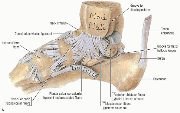
FIGURE 33-1. A: Medial view of the ligaments of the ankle. B: Lateral view of the ligaments of the ankle. C: Disarticulated talus. (From Agur AMR, Lee MJ. Grant’s atlas of anatomy, 10th ed. Philadelphia: Lippincott Williams & Wilkins, 1999, with permission.)
|
lateral collateral ligaments and the ligaments of the tibiofibular
syndesmosis. The deltoid ligament (i.e., medial collateral ligament) is
a thick, triangular band consisting of superficial and deep fibers. The
superficial fibers arise largely from the anterior colliculus of the
medial malleolus and run as a continuous sheet in the sagittal plane to
attach to the navicular, the sustentaculum tali, and the talus. The
intraarticular and more horizontal deep fibers run from the
intercollicular notch and posterior colliculus to the medial surface of
the talus.
 |
|
FIGURE 33-1. Continued.
|
 |
|
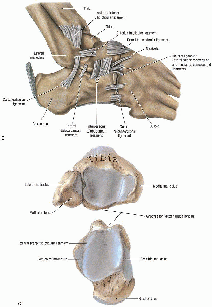
FIGURE 33-2. A: The anteroposterior radiograph demonstrates an isolated fibula fracture. B:
A stress view, taken with external rotation of the foot with the ankle in dorsiflexion, documents medial clear space widening and talar shift. |
constitute the lateral collateral ligament: the anterior talofibular
ligament, which runs from the anterior margin of the lateral malleolus
to the anterior lateral facet of the talus; the calcaneofibular
ligament, which extends down and posteriorly from the tip of the fibula
to a tubercle on the lateral aspect of the calcaneus; and the posterior
talofibular ligament, which originates on the medial surface of the
lateral malleolus and inserts on the posterolateral aspect of the talus.
joined together by four ligaments and the interosseous membrane. The
ligaments are the anterior inferior tibiofibular ligament, the
posterior inferior tibiofibular ligament, the inferior transverse
ligament, and the posterior talofibular ligament. These ligaments
stabilize the distal articulation of the tibia and fibula.
Nonoperative treatment is reserved for nondisplaced, stable fracture
patterns with an intact syndesmosis and for patients with marked
osteoporosis, arterial insufficiency, limited goals for ambulation, or
short life expectancy. Although it is possible to gain a satisfactory
or even anatomic reduction of a displaced malleolar fracture by closed
reduction, maintaining this reduction generally requires immobilization
in a nonfunctional position in a long leg cast for at least 6 weeks. It
is important to identify and separate patients with isolated fibular
fractures from those who have obvious or occult injury to the medial
side of the ankle. For patients with an isolated fibula fracture and
medial pain but no talar shift, stress radiographs should be taken. If
medial clear-space widening (>4 mm) with talar shift is present on
stress radiographs (taken with external rotation of the foot with the
ankle in dorsiflexion), the fibular fracture should be stabilized (Fig. 33-2).
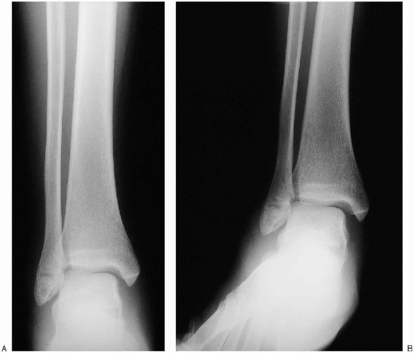
based on the position of the foot at the time of injury and the force direction (Fig. 33-3).
the fibula distal to the level of the joint or a rupture of the lateral
collateral ligaments.
ligament with or without an associated avulsion fracture at its tibial
or fibular attachment.
fracture of the distal fibula at or above the level of the syndesmosis;
this results from a bending force that causes medial tension and
lateral compression of the fibula, producing lateral comminution or a
butterfly fragment.
 |
|
FIGURE 33-3.
The Lauge-Hansen classification for ankle fractures is based on the position of the foot at the time of injury and the force direction. SA, supination-adduction; SER, supination-external rotation; PA, pronation-abduction; PER, pronation-external rotation. (From Carr JP, Trafton PG: Malleolar fractures and soft tissue injuries of the ankle. In: Browner BD, Jupiter JB, Levine AM, eds. Skeletal trauma, 2nd ed. Philadelphia: WB Saunders, 1998, with permission.) |
 |
|
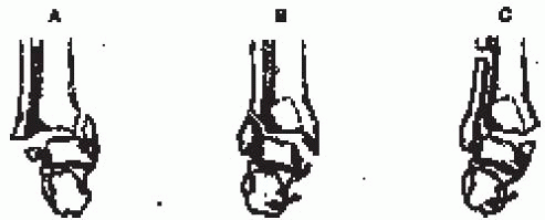
FIGURE 33-4.
The Danis-Weber classification is based on the level of the fibular fracture. (From Carr JP, Trafton PG. Malleolar fractures and soft tissue injuries of the ankle. In: Browner BD, Jupiter JB, Levine AM, eds. Skeletal trauma, 2nd ed. Philadelphia: WB Saunders, 1998, with permission.) |
fibula at or above the level of the syndesmosis running from
anterosuperior to posteroinferior.
the fibular fracture; the more proximal the fracture, the greater is
the risk of syndesmotic disruption and associated instability (Fig. 33-4):
of the tibial plafond, an avulsion injury that results from supination
of the foot and that may be associated with an oblique or vertical
fracture of the medial malleolus.
caused by external rotation occurring at or near the level of the
syndesmosis.
of the syndesmosis, causing disruption of the syndesmosis, and is
almost always with associated medial injury.
of ankle fractures is based primarily on fracture level in relation to
syndesmosis (Fig. 33-5):
|
Type A is an infrasyndesmotic lesion. |
|
|
A1: |
infrasyndesmotic lateral malleolus, isolated |
|
A2: |
infrasyndesmotic lateral malleolus with associated medial malleolar fracture |
|
A3: |
infrasyndesmotic lateral malleolus with associated posteromedial tibial fracture |
|
Type B is a transsyndesmotic lesion. |
|
|
B1: |
transsyndesmotic lateral malleolus, isolated |
|
B2: |
transsyndesmotic lateral malleolus with associated medial lesion |
|
B3: |
transsyndesmotic lateral malleolus with medial lesion and fracture of the posterolateral rim of the tibia |
|
Type C is a suprasyndesmotic lesion. |
|
|
C1: |
simple diaphyseal fibular fracture |
|
C2: |
complex (multifragment) diaphyseal fibular fracture with associated medial injury |
|
C3: |
proximal fibular fracture with associated medial injury |
 |
|
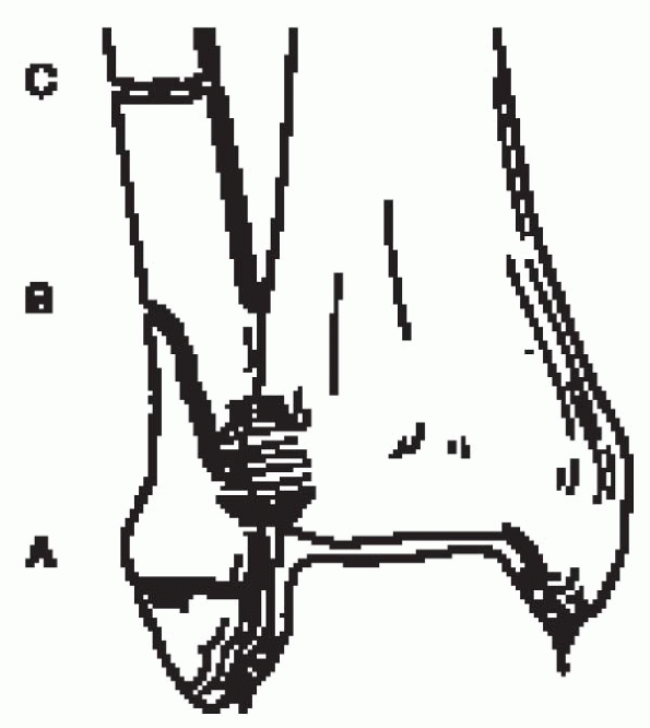
FIGURE 33-5.
The Orthopaedic Trauma Association (OTA) classification of ankle fractures is based on the fracture level in relation to the syndesmosis. (From Marsh JL, Saltzman CL. Ankle fractures. In: Heckman JD, Bucholz RW, eds. Rockwood and Green’s fractures in adults, 5th ed. Philadelphia: Lippincott Williams & Wilkins, 2001, with permission.) |
should include anteroposterior, mortise, and lateral views of the ankle
(Fig. 33-6). The surgeon should also ascertain that there is not a proximal fibula fracture by clinical or radiographic examination.
 |
|
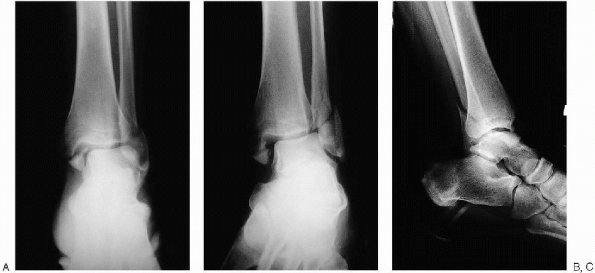
FIGURE 33-6. Anteroposterior (A), mortise (B), and lateral (C) views of the ankle demonstrate a displaced bimalleolar ankle fracture.
|
-
Tibiofibular overlap of less than 10 mm is abnormal and implies syndesmotic injury.
-
Tibiofibular clear space of more than 5 mm is abnormal and implies syndesmotic injury.
-
In a talar tilt, a difference in width of
the medial and lateral aspects of the superior joint space of more than
2 mm is abnormal and indicates medial or lateral disruption.
-
The dome of the talus should be centered under the tibia and congruous with the tibial plafond.
-
Posterior tibial tuberosity fractures can be identified, as well as the direction of fibular injury.
-
Avulsion fractures of the talus by the anterior capsule may be identified.
degrees of internal rotation to offset the intermalleolar axis, is used
to ascertain talar positioning:
-
A medial clear space of more than 4 mm is abnormal and indicates lateral talar shift.
-
In assessing talar tilt, a line drawn
parallel to the distal tibial articular surface and a second line drawn
parallel to the talar surface should be parallel. More than 2 degrees
of angulation indicates talar tilt. -
Tibiofibular overlap of less than 1 cm indicates syndesmotic disruption.
-
A talar shift of more than 1 mm is abnormal.
complex or comminuted fractures, especially of the distal tibia when
plain radiographs are not able to fully delineate the fracture extent
or in adolescents to demonstrate a possible triplane fracture.
-
Small fragment plate and screws
-
Pelvic instrument and implant sets
-
Kirschner wires (K-wires)
-
Small-diameter, cannulated screws
-
Large and small, pointed reduction clamps
-
Cerclage wire set
buttock on the injured side to aid access to the fibula. All pressure
points are padded. A pneumatic tourniquet is applied to the upper thigh
for use during surgery. The leg is prepared and draped free.
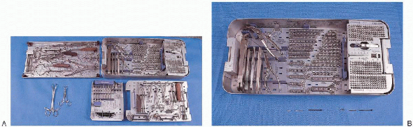 |
|
FIGURE 33-7. A: The basic instruments necessary for open reduction and internal fixation of the ankle include a cerclage wire set (top left tray); small fragment plate and screw set (top right tray); large and small, pointed reduction clamps (2) (bottom left); drill bits, taps, Kirschner wires, and bending templates (bottom tray, middle); and drill guides, screw driver, retractors, and reduction forceps (bottom right tray). B: Small fragment plate and screw set.
|
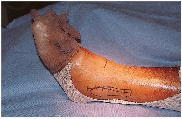
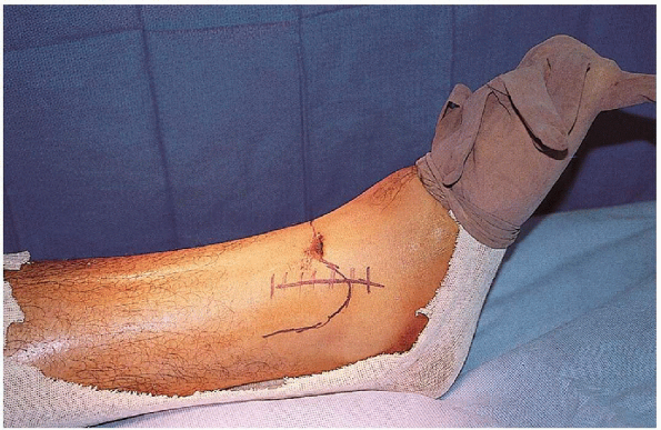
incision centered over the fracture and curving anterior distally to
allow access to the anterolateral corner of the ankle joint (Fig. 33-8).
The placement of this incision, however, may be adjusted, based on soft
tissue conditions such as the presence of blisters or abrasions (Fig. 33-9). The deeper tissue is dissected in line with the skin incision, taking care not to injure the superficial peroneal nerve. Division or entrapment of fixation devices the peroneal nerve in scar can lead to a symptomatic neuroma.
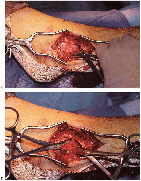
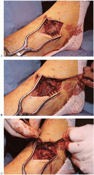
fibula, and the periosteum is incised over the lateral and posterior
aspect of the fibula (Fig. 33-10). The full
extent of the usual posterior fracture spike is exposed to allow proper
fracture reduction assessment. Soft tissue stripping of butterfly
fragments is kept to a minimum, particularly if there is comminution.
Exposure must be sufficient to allow placement of reduction forceps,
evaluation of the fracture reduction, and insertion of plate and screws.
the usual supination-external rotation injury, external rotation of the
foot opens the fracture surfaces and allows full exposure of the
internal and external aspects of the fibula for irrigation and clot
removal.
reduction can be accomplished by the use of clamps without strenuous
manual traction. A small reduction (lion jaws) clamp from the small
fragment set is placed obliquely across the fibula, perpendicular to
the fracture
plane (Fig. 33-12); this clamp is then used to obtain fracture length and rotation.  A second clamp can be placed proximal or distal to the first clamp and used to fine tune the fracture reduction. The
surgeon should avoid placing the reduction clamp around the thin
portion of the anterior or posterior fracture spikes to minimize the
risk of iatrogenic fracture comminution. If
there is significant fracture comminution or poor bone quality, the
surgeon can manually reduce the fracture and place provisional fixation
with two or three 1.6-mm K-wires inserted from the tip of the fibula
across the fracture.
 |
|
FIGURE 33-8.
The fibula is approached through a straight lateral incision centered over the fracture and curving anteriorly distally to allow access to the anterolateral corner of the ankle joint. |
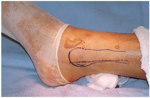 |
|
FIGURE 33-9. Modification of the lateral skin incision because of an anterolateral blister.
|
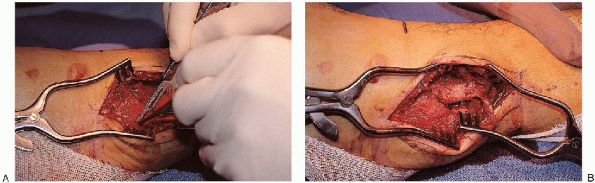 |
|
FIGURE 33-10. A and B:
The dissection is carried to the lateral border of the fibula, and the periosteum is incised over the lateral and posterior aspects of the fibula. |
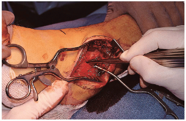 |
|
FIGURE 33-11. Removal of a clot from between the fracture edges.
|
 |
|
FIGURE 33-12. A and B:
A small reduction (lion jaws) clamp from the small fragment set is placed obliquely across the fibula, perpendicular to the fracture plane, to reduce the fracture. |
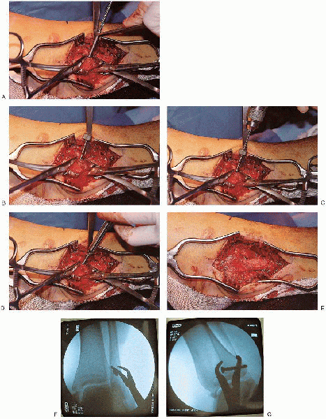
A 3.5/2.5 mushroom cap is then used to make a hole in the far cortex using a 2.5-mm drill. After measurement of the screw length and tapping of the screw tract, the lag screw is inserted. The surgeon must angle the drill bit laterally to capture the distal fragment.A one-third tubular plate is then contoured, placed laterally or
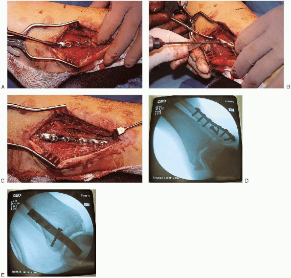
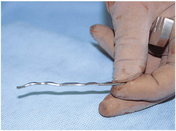
posterolaterally, and secured to the proximal and distal fragments (Fig. 33-14). The plate must be contoured
with a bend and a twist (Fig. 33-15). The
plate is bent so that it is concave just above the plafond level and
gently convex over the larger lateral malleolus itself.
This contouring is particularly important if fracture comminution
precludes use of a lag screw, because fracture reduction can be altered
by poor plate bending. I usually insert
the distal screw first and then verify that the proximal aspect of the
plate is centered on the fibula. After placement of a second screw, the
plate position is fixed, and the plate cannot be rotated to a better
position on the bone. With lateral plate placement, the distal
screws must remain unicortical to avoid intraarticular protrusion; the
proximal screws are bicortical.
 |
|
FIGURE 33-13. A:
A lag screw is placed from anterior to posterior across the fracture fragments. A gliding hole is made in the near cortex using a 3.5-mm drill. B and C: A 3.5/2.5 mushroom cap is then used to make a hole in the far cortex using a 2.5-mm drill. D and E: After measurement of the screw length and tapping of the screw tract, the lag screw is inserted. F and G: Fluoroscopic evaluation after lag screw insertion. |
 |
|
FIGURE 33-14. A to C:
Lateral plate placement with screw insertion proximally and distally. The most distal screw is usually inserted first and angled proximally. D and E: Fluoroscopic evaluation after plate insertion. |
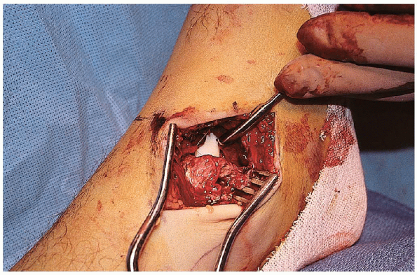
It is sufficiently long to allow fracture reduction and stabilization
without excessive soft tissue retraction. The saphenous vein and its
accompanying saphenous nerve branches are preserved. The medial border
of the medial malleolus is dissected of soft tissue and the fracture identified (Fig. 33-17).
The periosteum on either side of the fracture should be cleared for 2
to 3 mm to allow assessment of fracture reduction. The anteromedial
corner of the ankle joint is visualized and irrigated to determine the
extent of cartilage injury and remove any osteocartilaginous debris (Fig. 33-18).
 |
|
FIGURE 33-15.
The plate is contoured with a bend and a twist. The plate is bent so that it is concave just above the plafond level and gently convex over the larger lateral malleolus. |
 |
|
FIGURE 33-16. The medial incision is slightly curved and centered over the medial malleolus.
|
 |
|
FIGURE 33-17. A and B: Soft tissues is dissected off the medial border of the medial malleolus, and the fracture is identified. C: The periosteum is incised on either side of the fracture.
|
 |
|
FIGURE 33-18. Visualization of the anteromedial corner of the ankle joint.
|
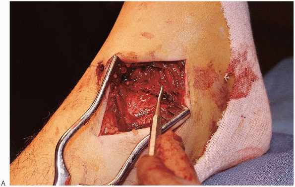
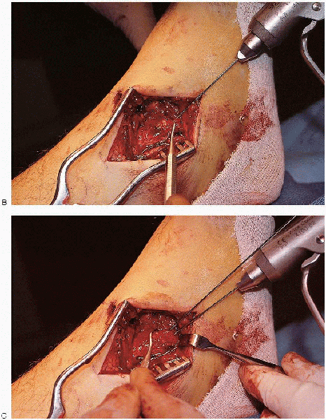
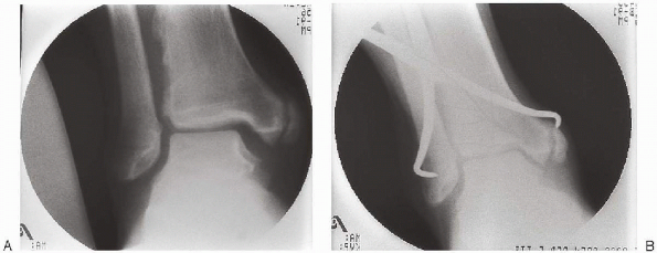
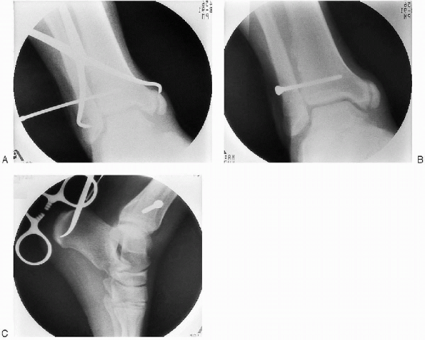
and provisionally stabilized using K-wires or reduction forceps (Fig. 33-19). Once satisfied with the fracture reduction visually and
radiographically, two 4.0-mm, partially threaded, cannulated cancellous
screws are inserted perpendicular to the fracture (Fig. 33-20).
For most fractures, these are placed halfway between medial cortex and
articular cartilage and angled proximally and laterally from the tip of
the malleolus to remain entirely within the malleolus and the distal
tibial metaphysis. Generally, 35- or 40-mm screw lengths are
sufficient, although this depends on the patient’s size and the
fracture pattern. It is better to stay within
the dense bone of the more distal tibial metaphysis, especially in
osteoporotic patients, than to use longer screws.
 |
|
FIGURE 33-19. A: Reduction of the medial malleolus using a dental pick.
|
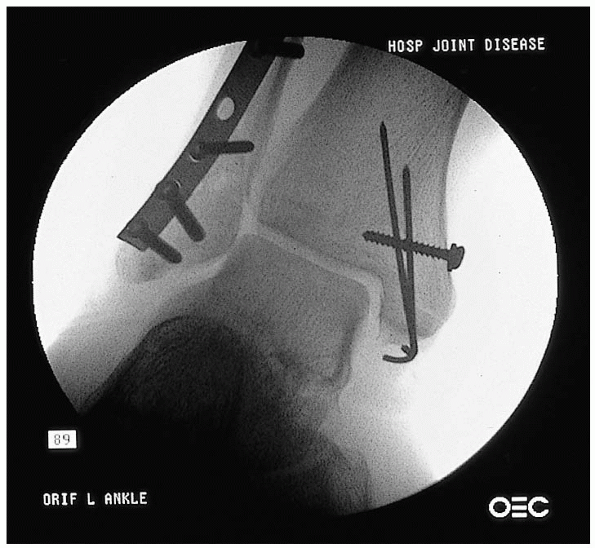
screw, typically in the larger anterior colliculus, with a parallel
K-wire in the posterior colliculus to prevent rotation. Bending the K-wire so its tip lies on the screw head aids hardware removal and minimizes the prominence.
Comminuted fragments may be stabilized with K-wires and a supplementary
“tension-band” suture or wire anchored around a proximal screw and
washer (Fig. 33-21).
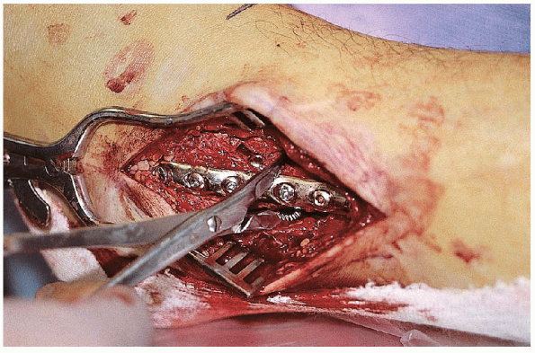
medial and lateral malleolar reduction and stabilization, the surgeon
should assess the status of the syndesmosis. Syndesmotic instability
can be assessed by pulling laterally with an instrument hooked around
the distal fibula or manually displacing the talus laterally with
external rotation (Fig. 33-22).
Displacement of more than a few millimeters, especially if there is
failure or elastic recoil to the anatomic position, is an indication of
soft tissue disruption and the need for syndesmotic screw fixation.
shape of the talus. A large tenaculum clamp placed across the distal
tibia and fibula can be used to provisionally stabilize the syndesmosis
(Fig. 33-23). After provisional fixation, radiographic confirmation of mortise alignment is obtained.
 |
|
FIGURE 33-19. Continued. B and C:
Provisional stabilization of the fracture using two Kirschner wires. If these wires are in a good position, they can be used for insertion of a cannulated lag screw. |
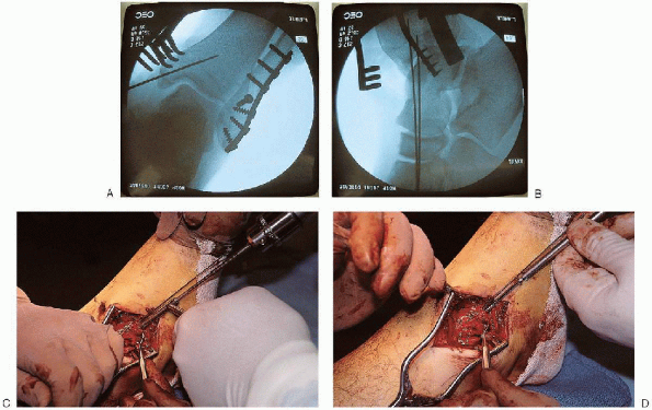 |
|
FIGURE 33-20. A and B: Fluoroscopic evaluation of the fracture reduction and Kirschner wire position. C and D: Insertion of two 4.0-mm, partially threaded, cannulated cancellous screws.
|
 |
|
FIGURE 33-21.
A small medial malleolar fragment is stabilized with Kirschner wires and a supplementary “tension-band” suture anchored around a proximal screw and washer. |
 |
|
FIGURE 33-22. Assessment of syndesmotic stability by pulling laterally with a reduction clamp placed around the distal fibula.
|
 |
|
FIGURE 33-23. Reduction of a widened syndesmosis (A) using a tenaculum clamp placed across the distal fibula and tibia with the ankle in dorsiflexion (B).
|
cortices of fixation remain controversial. However, I generally
stabilize the syndesmosis using a fully threaded, 3.5-mm cortical screw
placed through three or four cortices (Fig. 33-24). The
advantage of placing the syndesmotic screw through four cortices is
that, if the screw breaks, the tibial portion can be removed through a
medial incision. This screw is inserted parallel to the ankle
joint, from the posterolateral fibula to the anteromedial tibia, 1.5 to
2.0 cm above the plafond. If a plate was used for fibular fixation, it
is often possible to place this screw through one of its holes.
protruding a couple of millimeters on the medial side.
 |
|
FIGURE 33-24. A to C: Stabilization of the syndesmosis using a fully threaded, 3.5-mm cortical screw placed through three cortices.
|
anatomic fibula reduction. Dorsiflexion of the foot may assist in
reduction by a ligamentotaxis effect from the posterior capsule. If the
fragment is large and involves more than 25% of the articular surface
of the distal tibia, I favor fixation, particularly if associated with
posterior talar subluxation or dislocation. The posterior malleolus may
be stabilized using lag screws inserted in a posterior-to-anterior or
anterior-to-posterior direction.
 |
|
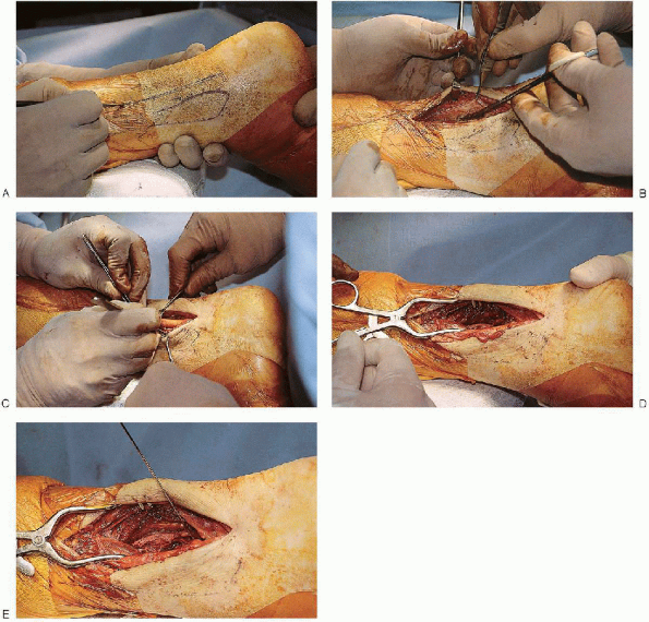
FIGURE 33-25.
Exposure of the posterior malleolus can be performed from a posterolateral approach. The skin incision is placed posterior to the fibula (A). The approach uses the interval between the peroneal tendons and the flexor hallucis longus muscle (B and C) to expose the distal aspect of the posterior tibia (D and E). |
requires direct reduction, exposure of this fragment and of the lateral
malleolus can be performed from a posterolateral approach. The skin
incision is placed posterior to the fibula. The fibula is reduced
first. The approach then uses the interval between the peroneal tendons
and the flexor hallucis longus muscle to expose the distal aspect of
the posterior tibia (Fig. 33-25). The external
edges of the fracture are used as a guide to anatomic reduction and the
posterior malleolus fracture stabilized with one or two cancellous
screws directed from a posterior to an anterior direction (Fig. 33-26).
 |
|
FIGURE 33-26. A and B: Stabilization of the posterior malleolus using two cancellous screws directed from posterior to anterior aspects.
|
 |
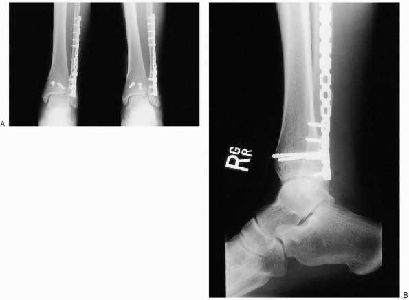
|
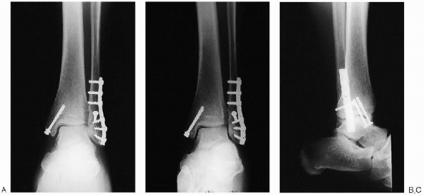
FIGURE 33-27. Final intraoperative anteroposterior (A), mortise (B), and lateral (C) radiographs.
|
range of motion to assess fixation stability. Intraoperative
radiographs are also taken to ensure that reduction and fixation are
adequate (Fig. 33-27). I obtain anteroposterior, mortise, and lateral views.
compartments but may be closed distally over the malleoli. The
subcutaneous tissue is reapproximated using Vicryl sutures. The skin is
closed with nylon using vertical mattress sutures to evert the wound
edges. Tight closure should be avoided because of the tendency for the leg to swell in the early postoperative period. If
the wound is too swollen to close without excessive tension, the wound
should be left open and a delayed wound closure performed. A bulky dressing is applied with a posterior and U-shaped splints holding the ankle in a neutral position.
as possible for the first week after surgery. They are instructed in
ambulation training while not bearing weight on the injured extremity.
At the first postoperative office visit, the leg is placed in a
removable functional brace, and the patient is instructed on active and
passive range-of-motion exercises of the ankle and subtalar joint. The
brace is removed several times each day for active range-of-motion
exercises. As the patient becomes more comfortable, gentle but
progressive passive dorsiflexion stretching is added.
individuals in whom a syndesmosis screw had been used. These patients
do not bear weight on the affected site for 8 weeks, at which time the
screw is removed. Postoperative radiographs are obtained at 2 and 6
weeks. After the patient is allowed to bear weight as tolerated,
resistive exercises are initiated.