
VIII – THE SPINE > Principles and Anatomy > CHAPTER 137 –
BIOMECHANICS OF SPINAL INSTRUMENTATION
Department of Biomedical Engineering; Professor, Department of
Orthopaedic Surgery; Co-Director, Iowa Spine Research Center,
University of Iowa, Iowa City, Iowa, 52242.
function is to protect the spinal cord from damage while allowing
physiologic motions at each vertebral level. Many times, especially in
disease states or in the case of trauma, vertebral motion may produce
impingement on the spinal canal, resulting in elevated pressure on the
spinal cord. Some spinal disorders may reduce mechanical stability,
resulting in abnormal motion, pain, or deformity in the face of normal
loads and activity. The primary goal of surgical intervention is to
relieve extraneous spinal pressure, reduce the patient’s pain, and
obtain correct spinal alignment.
the long-term goal of surgery. It is commonly achieved by open
reduction and bone grafting, with the postoperative reduction
maintained by fixation implants. Each stage in treatment has an
associated biomechanical implication that cannot be overlooked.
spinal structures, particularly the facet joints and intervertebral
disc. The spine exhibits two types of motion: in-plane and “coupled”
motion. Coupled motion is defined as movement that is out of the plane
of the applied loads. The orientation of the facet joints primarily
determines the magnitude of in-plane and coupled motion.
partially by the intervertebral disc and ligaments. Hyperextension, for
instance, is limited by the anterior longitudinal ligaments and the
anterior portion of the annulus fibrosis (16).
Flexion is limited primarily by the posterior ligamentous complex and
capsules of the facet joints. The degree of lateral bending is usually
checked by the capsular ligaments and facet joints. Axial rotation is
regulated by the intervertebral discs including Luschka’s
joints
(cervical spine), facet joints, and capsular, interspinous, and
supraspinous ligaments. It has been demonstrated that 90% resistance to
axial rotation in the lumbar spine is provided by the facet joints and
intervertebral discs; the ligaments are responsible for the remaining
10% (10).
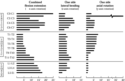
Both the occipitoatlantal and atlantoaxial levels allow greater than
20° of flexion and extension. Also, the C1–C2 facets and the
atlantodental articulation allow for 40° to 50° of axial rotation to
each side. The lower cervical spine (C3–C7) exhibits more lateral
bending than the occipitoatlantoaxial complex. Sagittal plane and axial
rotation diminish from the C4–C5 level and below.
 |
|
Figure 137.1.
Mapping of the normal ranges of motion in combined flexion and extension, lateral bending, and axial rotation as a function of spinal position. Note that these values should not be regarded as absolute and that considerable variation exists within the population. (From White AA, Panjabi MM. Clinical Biomechanics of the Spine, 2nd ed. Philadelphia: J.B. Lippincott Co., 1990:107, with permission.) |
thoracic region is the least mobile portion of the spine. The upper
thoracic spine allows significant axial rotation (approximately 10°),
but below T8–T9, the major motion of the thoracic spine is in flexion
and extension. The lumbar spine permits a significant degree of flexion
and extension across all levels. There is a sharp increase in the
amount of lateral bending exhibited by the L3–L4 level, with a
corresponding decrease at the L2–L3 and L4–L5 motion segments. Axial
rotation in the lumbar spine is limited by the vertical orientation of
the facet joints.
integral to the diagnosis and treatment of the lumbar spine.
Instability of the spine can be a result of a purely mechanical
disorder or a disorder of another origin.
unnecessary surgery in some cases or inadequate treatment in others.
Unrecognized and untreated instability exposes the patient to an
increased risk of neurologic injury, pain, and in the upper cervical
spine, mortality. White and Panjabi (54) define
clinical instability as “the loss of the ability of the spine under
physiologic loads to maintain its pattern of displacement so that there
is no initial or additional neurological deficit, no major deformity,
and no incapacitating pain.” The key phrase within this definition, for
the purpose of understanding stability, is “to maintain its pattern of
displacement.” Trauma, degeneration, and certain clinical procedures
can severely alter the spine’s normal pattern of displacement and lead
to instability.
has been developed to help the physician determine the degree of
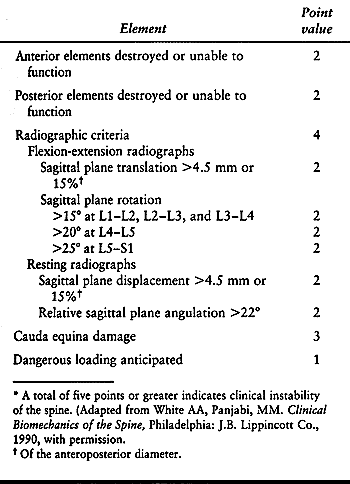
instability; see Table 137.1. (43)
Radiographs of the spine are taken, whereupon the physician assigns a
certain number of points depending on range of motion and condition of
spinal elements. According to this system, a total of five points or
more indicates a clinically unstable spine.
 |
|
Table 137.1. Checklist for the diagnosis of clinical instability of the lumbar spine*
|
of the anteroposterior diameter of the vertebral body or relative
angulation greater than 22° denotes potential instability (45,50).
Also, relative sagittal rotation greater than 15% at L1–L2, L2–L3, and
L3–L4; greater than 20° at L4–L5; or greater than 25° at L5–S1
represents an abnormal range of motion and potential instability (54). The presence of a neurologic deficit is also diagnostic of spinal stability.
Within the neutral zone, there is minimal resistance to intervertebral
motion; minor changes in load result in considerable shifts in
position. A patient in pain may reveal an increase in the neutral zone,
allowing motion to occur beyond the pain-free zone under physiologic
loads, while showing no change in the spine’s overall range of motion.
In contrast, when the spine is stabilized, pain may decrease because of
a decrease in the range of the neutral zone as well as the overall
range of motion.
instability within the lumbar spine through the use of magnetic
resonance imaging (MRI), computed tomography (CT) scans, and
radiographs, which can indicate the spine’s range of motion. (Take care
to identify whether the data are based on active or passive range of
motion, because there is a difference between the two.) Many recent
studies have also postulated that a measurement of the time course of
motion within the spine may be as important as range of motion in
determining degrees of instability (34,40).
acceleration of movement give key insight into the patient’s condition.
Slow motion could indicate a patient’s lack of confidence or pain.
Jerky movements may be indicative of a lack of fine motor control. Some
studies suggest that the dynamics behind the movement of the spine are
subject to a great amount of variability depending on neuromuscular
coordination, motivation, skill, physiologic strength and flexibility,
and metabolic support (24).
speed at which the patient moves is unknown. No conclusive evidence has
indicated that velocity measurements are more sensitive to impairment
than ROM measurements. The large amount of variability found in studies
that examine movement velocity for diagnostic purposes has limited the
clinical usefulness of such measurements. Therefore, a dynamic analysis
of the spine should be used as a supplement to static radiographs for
the determination of spinal instability; flexion and extension x-ray
studies are the most widely used studies for this purpose.
degeneration, tumor, infection, muscle dysfunction, surgical
intervention, or any combination thereof. Damage to any portion of the
functional spinal unit (vertebra-disc-vertebra assembly) can lead to
instability. The most important spinal elements contributing to
instability are the intervertebral disc, facet joints, and the
perispinal ligaments. It is often necessary to dissect some or all of
these components during spinal surgery. Just exposing the spine can
damage fine nerves that contribute to muscle function and coordination (38,44).
Nerve damage can upset the normal distribution and transmission of
loading, leading to further instability. Thus, it is necessary to
describe the biomechanical effects due to partial or complete spinal
element removal. The three most common procedures involving spinal
element resection are laminectomy, facetectomy, and partial or complete
removal of the intervertebral disc.
posterior vertebral arch to decompress the neural elements, cord and
nerve roots. Partial laminectomy does not necessarily result in
instability. Cadaver experiments show that partial laminectomy has a
greater effect on the amount of flexion and axial rotation
(approximately a 15% to 20% increase) than lateral bending (less than a
5% increase) (23). Controversy exists as to
whether fusion is necessary following laminectomy procedures.
Degenerative spondylolisthesis cohort studies suggest that laminectomy
with fusion results in a decrease in pain, with increased stability.
However, follow-up studies on patients who had laminectomies for spinal
stenosis showed no difference in outcome whether or not a coincident
fusion procedure was performed. It appears that an indication for
fusion depends more on the evidence of pre-existing instability than on
the decompression itself.
determining the relative amount of motion at each spinal level. In
particular, the facets serve to resist axial rotation and extension
motion. Farfan et al. (10) demonstrated that,
in the lumbar region, the facets alone resist approximately 50% of the
torsional loads experienced by the spine.
of these vertebral elements would result in an unstable spine. In fact,
however, partial unilateral or bilateral facetectomy at one level
results in greater motion but may not produce instability (23).
Complete facetectomy (unilateral or bilateral) increased motion by 78%
in extension, 63% in flexion, 15% in lateral bending, and 126% in axial
rotation as compared with the intact controls, confirming that the
degree of instability can be directly correlated with amount of facet
removal.
The intervertebral disc can degenerate, becoming dehydrated and
fissured, resulting in nonphysiologic loading (18).
The nucleus pulposus can evidence fibrous tissue formation, leading to
nonhomogeneous stresses within the disc. The intervertebral disc, which
may protrude or herniate, causing nerve root compression, has been
implicated as common source of low back pain (“discogenic pain”). Thus,
many surgical interventions involve removing part or all of an
intervertebral disc, as do interbody fusion techniques.
instability. It has also been shown that discectomy with minimal
removal of the lamina does not produce instability. In fact, complete
discectomy (partial laminectomy, partial facetectomy, partial annulus
removal, and complete nucleotomy) results in an 80% increase in
flexion, an increase of 60% in extension, a 38% increase in lateral
bending, and a 62% increase in axial rotation (14). Postdiscectomy back pain may be associated with more extensive disc removal at the time of surgery.
used to treat ailments ranging from fractures and tumors to
spondylolisthesis and disc degeneration. Eliminating motion between the
affected segments increases the likelihood of fusion and may reduce the
degree of pain the patient experiences (41,53).
Properly applied, spinal instrumentation maintains alignment and shares
spinal loads until a solid, consolidated fusion is achieved.
the number of available fixation systems has grown. With few
exceptions, these systems are used in combination with bone-grafting
procedures and may be augmented by external bracing systems.
in terms of where the hardware is attached: anterior, posterior, or
interbody.
-
The “anterior” devices such as anterior
plates and screw systems usually are classified as those systems that
are designed to attach to the anterior or anterolateral aspect of the
vertebral body. Typically, the plate or rod construct is transfixed to
the involved vertebral segments by screws that pierce one or both
cortices as well as gain purchase in the cancellous bone of the
vertebral body. -
“Posterior” systems are affixed to the
elements situated posterior to the vertebral body, the spinous
processes, pedicles, facets, or laminae. These instrumentation systems
use laminar hooks, pedicle screw systems, facet screws and wiring
techniques. -
Finally, interbody fusion systems promote
fusion between the vertebral bodies by the incorporation of a device or
graft that spans the disc space. Although allograft and autograft
spacers are routinely used in combination with other anterior or
posterior instrumentation, a variety of “stand-alone” devices are now
available and approved for implantation. Usually, the interbody systems
are further classified by the surgical approach used during device
implantation. The comingling of system and approach has given rise to
such contemporary terminology as anterior lumbar interbody fusion
(ALIF), transforaminal lumbar interbody fusion (TLIF), and posterior
lumbar interbody fusion (PLIF) procedures.
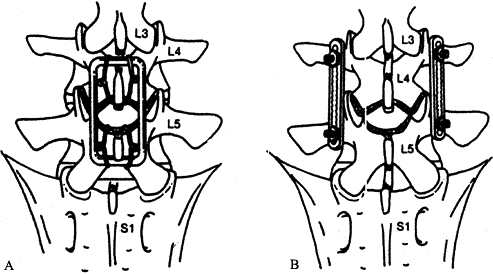
the posterior fusion technique. The concept originated using the
midline fusion technique wherein the graft material spanned adjacent
spinous processes and lamellae (Fig. 137.2A).
This technique is biomechanically disadvantageous. The graft material
is situated far from the center of rotation and experiences tensile
forces when the spine is put in flexion, both factors that may induce
excessive motion and cause the graft to migrate before it can
incorporate and consolidate. The measured stress increases as the
distance from the center of rotation increases; thus, grafts placed at
this distance may result in a nonunion due to resorption or material
failure. In addition, tensile loads experienced by the graft also may
cause it to fail because bone is inherently more stable in compression
than in tension. The clinical outcome is delayed union or nonunion.
 |
|
Figure 137.2. Schema depicting two types of posterior fusion devices. A: The Luque Loop application is a midline procedure that uses wiring to achieve fixation to the spine. B:
The posterolateral application of Steffee plates involves pedicle screw fixation (From Goel VK, Lim TH, Gwon J, et al. Biomechanics of Fusion. In: Andersson GBJ, NcNeill TW, eds. Lumbar Spinal Stenosis. Chicago: Mosby–Year Book, 1996:403, with permission.) |
relatively high pseudoarthrosis rate with early posterior fusion
techniques. The most commonly employed contemporary method of fusion,
the posterolateral fusion technique (Fig. 137.2B), addresses many of these flaws. The posterolateral technique involves fusion of the transverse
processes and the facet joints of adjacent vertebrae. The
intertransverse fusion allows placement of the graft in closer
proximity to the center of vertebral rotation than the midline fusion,
thus reducing the tensile loads experienced by the graft and decreasing
the risk of graft migration.
solid fusion. Although aggressive removal of the facet cartilage does
reduce the inherent stability of the motion segment, the increased
surface area for fusion and close apposition of the facet joint
surfaces facilitates the rate of fusion. Internal fixation using
wiring, pedicle screw fixation, and hooks usually reduces the risk of
graft displacement by decreasing displacement and the loads through the
graft during the healing process.
distraction devices, using hooks to force the laminae apart and
straighten the spine. Sublaminar wires were the first implant used to
provide “segmental” fixation, attaching the rod to the spine at
multiple points along the length of the construct. They are still used
in deformity surgery, but because they do not provide axial stability,
they are a poor choice for stabilizing fractures or bone loss due to
tumors. Sublaminar wires have greater leverage in directly pulling the
displaced element to the correcting rod than the distraction systems
could safely generate, but they cannot prevent these elements from
sliding down the rod should adjacent levels collapse.
attach to multiple points along the construct, and they offer a means
of locking the hook to the rod at any given point to maintain axial
distraction or compression forces after implantation. Pedicle screws,
large fixation screws implanted through the lamina and pedicle into the
vertebral body, allow segmental fixation even in areas where the
laminae have been removed. Pedicle screws are the only devices
available that provide fixation to all three vertebral columns. When
used in combination with sublaminar wires and pedicle screws,
contemporary posterior instrumentation systems are highly versatile and
effective devices.
use. These systems provide a high degree of construct stability as well
as afford good fixation to the spine. Because pedicle screws are
inserted into the vertebral body, these posterior devices can directly
manipulate the intervertebral space. Pedicle screws also allow one to
apply distraction, compression, lordosis, rotation, and anterolisthesis
or retrolisthesis forces selectively. They are the most important
factor that provides torsional stiffness in thoracolumbar spinal
constructs. Pedicle screw systems provide a means to treat
thoracolumbar instability after burst fracture or resection of a spinal
tumor. However, they must be augmented with anterior column support to
avoid exposing the screws to excessive cantilever loads that might
cause bending failure or breakage.
have increased, additional modifications have become essential to
increase their effectiveness and compensate for the shortcomings of the
system for a given indication. For example, studies reported a high
rate of screw failure when first-generation screws were used to treat
thoracolumbar burst fractures (39). Implant
failure, by either acute bending failure (postyield deformation) or
acute fracture, was seen in young patients with axial instability due
to trauma. Screw failure contributed to loss of alignment and fixation.
Loosening, toggling, or backing out of the screw owing to failure of
bone may occur, early or late, in older patients with weak,
osteoporotic bone.
period, often results in asymptomatic screw breakage and is usually not
a problem clinically. To reduce screw-bone interface
problems, augmentation of thoracolumbar constructs with offset laminar hooks has been recommended (51).
Laminar hooks help decrease the load transmitted between the bone and
pedicle screws, thereby protecting the screws and the bone. Injection
of bone cement in the hole before insertion of the screw has also been
suggested to increase the bone–screw interface strength, but this
approach has limited effectiveness in severely osteoporotic patients
and introduces some very real, if uncommon, risks.
loosening and fixation failure and by acute or subacute bending failure
or breakage. Loosening occurs as repetitive loading persists beyond the
tolerance of the bone, which is usually due to delayed union or
excessive activity. The screw is exposed to a combination of cantilever
bending and axial pullout loads. Cantilever bending loads may also
exceed the yield point of the screws, resulting in acute bending
failure and breakage. Even in the degenerated and collapsed disc, axial
loads impart small cyclic displacements that generate significant
cantilever loads and bending moments. These are most pronounced around
the screw hub, inside the pedicle. When the pedicle screws are forced
to bear most or all of the anterior column’s axial loads, as in burst
fracture or tumor reconstruction, excessive bending moments predictably
lead to screw failure and progressive kyphosis.
that it gives direct access to the area of disease, which is frequently
the disc or vertebral body. The anterior approach allows the surgeon to
decompress the neural structures, resect the disease, reduce deformity,
and stabilize the injured segment. Fusion anteriorly has the mechanical
advantage of being in closer proximity to the vertebral center of
rotation, thus reducing the stresses on the graft and hardware, as well
as being placed in compression.
forces acting on the thoracic and thoracolumbar spine—the anterior
compressive forces generated by gravity, posture, activity, and
muscular contraction. Unopposed, these forces lead to progressive and
disabling kyphosis. Whereas posterior systems depend on long lever arms
and cantilever forces to resist kyphotic collapse, anterior struts are
loaded in nearly pure compression, the cortical bone’s strongest
aspect. Anterior instrumentation need only share the compressive load
and resist translation and torsion to be effective.
have demonstrated the efficacy of obtaining a solid fusion when
anterior instrumentation is used. These studies also indicate that
fusion mass consolidation is greater when anterior instrumentation is
used, resulting in higher torsional stiffness of the fused levels. Most
anterior fixation systems use screws placed into the vertebral body
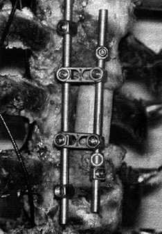
with rods or plates, or both (Fig. 137.3). The
weak link in these constructs is most often the bone–screw interface,
or fatigue failure of the implant occurs due to nonunion.
 |
|
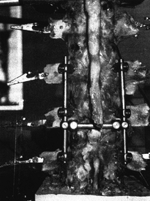
Figure 137.3.
An example of an anterior instrumentation device (applied to a cadaveric specimen). This device (ALC dynamized system, AcroMed, Inc., Cleveland, OH) uses screws driven into the vertebral body with bars spanning between the screws. These devices are commonly used in conjunction with vertebrectomy procedures. |
important feature associated with immediate postoperative stability,
the higher stiffness fixation systems can, in time, impart
progressively deleterious effects. “Stress shielding” is a phenomenon
that occurs with both anterior and posterior devices when a relatively
stiff implant bears a disproportionately large amount of physiologic
loads compared with the host bone. The biologic response of the bone to
the reduction in load is resorption of the bone around the implant.
the implant can lead to progressive angular deformities and loss of
fixation of the implant to the bone owing to weakening or resorption of
the bone around the implant, which leads to migration of the implant in
the bone. More rigid fixation, however, has been associated with
greater degrees of immediate postoperative stability. Thus, the dilemma
is that although higher implant rigidity is needed in the immediate
postoperative period, it may contribute to stress shielding as time
proceeds.
construct remains unclear. Additionally, the controlled subsidence of
the graft into the vertebral endplate may be a contributing factor to
successful fusion, which stiffer implants may impair. At the extreme,
resorption of the graft adjacent to a rigid implant may convert a
“load-sharing” device to a “load-bearing” device, leading predictably
to implant failure.
The flexible devices theoretically permit more load-bearing through the
interbody bone graft. They may not, however, provide the same degree of
immediate stability until fusion occurs. In newer implants the rigidity
of the device decreases as a function of time, providing a rigid
construct for the initial healing phase and thereafter permitting
larger loads through the fusion site because of a gradual decrease in
the rigidity of the device (20). The newer
anterior as well as posterior “dynamized” systems seek to allow a
preset degree of axial subsidence due to graft resorption and settling,
thereby allowing temporal load-sharing as graft consolidation proceeds (28). These devices are quite new, however, and are still in evaluation and thus not accepted for general use.
surgical procedures invariably leads to a loss of disc height and an
unstable segment. Both allografts and autologous bone grafts have been
used as interbody spacers. Autogenous bone grafts have the disadvantage
of donor site morbidity, and both autografts and allografts are subject
to dislodgement when used anteriorly, resulting in loss of alignment.
materials has gained popularity. These inserts may be implanted through
an anterior or posterior approach.
mesh promote fusion by imparting immediate postoperative stability,
promoting fusion through the incorporation of bone chips packed inside
the cage (29). Anterior procedures used to
implant cages usually require extensive removal of the anterior portion
of the annulus fibrosis and anterior longitudinal ligament. The
strength of the construct relies in part on distraction, which produces
tension in the remaining annulus (11).
various posterior elements. Iatrogenic or acquired (spondylolytic)
posterior column instability frequently requires posterior fixation.
Combined anterior or posterior interbody fusion and posterior
instrumentation and fusion in the lumbar spine usually requires partial
or complete facetectomy, removal of the pars interarticularis, and
partial or complete discectomy. These constructs require a significant
amount of load-bearing by the graft (and cage) construct and posterior
hardware to resist translation and torsion forces (47).
large part, from a desire on the part of surgeons to improve success
rates. The operative assumption is that better instrumentation will
produce better surgical results, whether success is defined in terms of
fusion rate, correction of deformity, pain relief, or hardware
survival. Thus, it is no surprise that the engineering community, in
concert with surgeons, is constantly evaluating the mechanical
performance of spinal instrumentation.
have appeared in peer-reviewed journals publishing data on a multitude
of clinically relevant mechanical parameters, collected using an
equally large and diverse number of in vitro and in vivo
testing methods. The literature can be loosely divided into several
distinct categories that outline the stepwise evolution that typically
occurs in the design and development of spinal implants and subsequent
release for clinical use (1,2,13,46). The majority of data deal with three mechanical parameters: construct stiffness, load to failure, and fatigue load (7,12,26,29,42,55,59,60).
resultant displacement. The failure load defines the maximum load that
can be applied to the construct before component or fixation failure
occurs. Fatigue load is usually defined as the number of loading
cycles, at physiologic loading levels, that can be applied to a given
system before hardware or fixation failure.
motion between the affected levels; thus knowledge of the construct
stiffnesses in flexion, extension, lateral bending, and axial rotation
is requisite for a complete understanding of a particular hardware
system. Load-to-failure studies reveal how the implant is likely to
behave when it is first applied. Fatigue studies give insight into the
likelihood and type of failures to be expected when the system is
exposed to normal loads over time. Several important categories of
biomechanical testing modalities illustrate the nature and value of
data obtained from each study type.
-
Interconnection testing
of spinal instrumentation systems has become increasingly more common,
owing to the complexity of contemporary designs. This type of testing
seeks to characterize mechanically the slip and failure properties of
the various interfaces within
P.3626
the device (Fig. 137.4).
Interconnection testing performed for pedicle screw and rod systems can
assess the failure load needed to produce appreciable slip at the
screw-rod junction.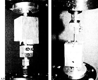 Figure 137.4.
Interconnection testing seeks to characterize mechanically the
interfaces within an assembled device. Pictured are two examples:
testing of the hook–rod interface (A) and the screw–rod interface (B).Because these tests are standardized as to configuration and loading, comparisons between various studies can be made. Figure 137.5,
for example, shows the loads needed to produce failure slip under both
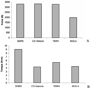
axial and rotational forces for many contemporary lumbar designs (21).![]() Figure 137.5. Data from interconnection testing for both (A) axial load and (B)
Figure 137.5. Data from interconnection testing for both (A) axial load and (B)
axial rotation. The four systems tested were the Surgical Dynamics
Rodding System (SDRS), Cotrel-Dubousett Horizon (CD-Horizon), Texas
Scottish Rite Hospital (TSRH), and ISOLA system. -
Plastic vertebrae (simulated corpectomy) models
are tests that mimic the performance of fixation devices under the
worst possible clinical scenario, which is where an anterior gap is
produced by vertebrectomy. Tests using plastic models standardize the
bone-screw interface and, thus, highlight the performance of the
assembled device as distinguished from the bone-screw interface. The
devices are mounted onto molded plastic vertebral components (Fig. 137.6) (8,48)
and subjected to axial compression, compression-flexion bending, and
torsional modes, loading either statically or cyclically (fatigue
testing).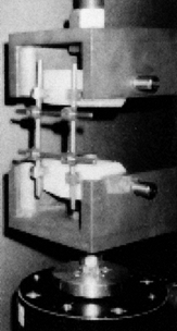 Figure 137.6.
Instrumentation testing using the plastic vertebrae model. The
construct is assembled with the two plastic blocks representing the
vertebral bodies. The assembly depicted here is being subjected to a
combined loading of flexion and compression.Results show that most devices fail at up to 50% less
load, when fatigue tested to 5 million cycles, as compared to the loads
they can withstand when loaded statically (22).
Failure always seems to occur at points of stress concentration, such
as attachment of the rod to the screw, at threads in the rod, at the
junction of the cross-links, and in the longitudinal members. These
failure patterns are supported by pedicle-screw loading studies.P.3627One such study (56) demonstrated
that the maximum stresses are seen near the hub of the screw and decay
nonlinearly to zero at the screw tip. Additionally, the stress
concentrations introduced by the geometry of the screw hub–shaft
junction increased the stresses experienced by the screw such that the
screw would be at risk of fatigue failure. Biomechanical studies using
analog models have shown that even small changes in screw orientation
or insertion technique can affect screw bending moments (35,36 and 37).
Thus, it seems that with the development of more versatile pedicle
screw systems, the clinical ease for implanting the devices may improve
but may introduce additional stress concentration sites. This type of
testing clearly shows the need for coordination between implant design
engineers and clinicians to ensure that the likely locations of failure
will be the least problematic.Tests of the compression strength of cortical and
cancellous bone dowels and cortical femoral rings, inserted between
plastic blocks having matching geometry and loaded in axial compression
using a servohydraulic testing machine, have shown that fresh human
cancellous bone fails at an average load of 863 N, whereas cortical
bone dowel strength may exceed 24,000 N (4). -
The strength of the bone–implant interface
is as important as the strength of the implant in preventing failure.
Axial pullout tests, which evaluate the fixation characteristics of
different screw types (31), have led to optimization of screw placement (6)
and thread design, producing instrumentation systems that are less
likely to fail clinically owing to fixation failure. Use of offset
hooks has been suggested as a supplement to pedicle screw fixation.
Yerby et al. (57) demonstrated that hook
augmentation to screw fixation decreased the bending moment experienced
by pedicle screws by approximately 30%, leading to reduced screw
migration during in situ contouring of the rods.The strength of pedicle screw fixation can be augmented
by filling the screw holes with hydroxyapatite grouting material. This
method can increase screw purchase in situations in which the bone
quality is diminished.In an animal study, Spivak et al. (49)
used hydroxyapatite as a grouting material for posterior screw
placement. They showed that grouting significantly improved screw
pullout strength 6 weeks following implantation. Histologic analysis
showed that this was most likely due to new bone formation within the
grout material around the screw.In an acute pullout study, Yerby et al. (58)
performed similar testing to determine the potential improvement in
fixation provided by hydroxyapatite augmentation for revision pedicle
screws. They simu- lated revision by pulling out 6.0 mm screws and
replacing them with 7.0 mm screws. The results showed that
hydroxyapatite augmentation increased the pullout strength by 325%.
They also showed that 7.0 mm screws that pulled out could be salvaged
by augmention with hydroxyapatite.Pullout studies have also been used to study the
parameters governing cage migration and extrusion in the immediate
postoperative period. Brantigan and Steffee (5)
reported that an average force of 342 N was required to dislodge their
fiber cage, whereas a force of 122 N was required to extract
rectangular PLIF bone plugs. Bagby and Kuslich (3)
determined that a mean force of 569 N was needed to dislodge the BAK
interbody fusion cage, compared with a mean force of 271 N for
corticocancellous bone dowels. -
Cadaveric construct testing (Fig. 137.7)
provides important information about the effectiveness of a device in
reducing intervertebral motion across the affected and adjacent
segments during quasiphysiologic loading.![]() Figure 137.7.
Figure 137.7.
Cadaver construct testing is an important evaluation in the testing
protocol. In this example, a pedicle screw system is applied to the
lumbar spine and pure moments are applied to the superiormost vertebra.
The motion of each lumbar vertebra is tracked to determine the
hardware’s effectiveness in reducing motion at the affected and
adjacent levels.For example, a cadaver study (28)
was used to compare the load-deformation characteristics of three
different anterior devices: the Synthesis Anterior Thoracolumbar
P.3628
Locking
Plate (ATLP, Synthes, Paoli, PA), the AcroMed Smooth Rod Kaneda System
(SRK, AcroMed Corp., Cleveland, OH), and Z-Plate (Sofamor-Danek, Inc.).
Loads of 0 to 6 Nm were applied in increments of 1.5 Nm to
thoracolumbar spine segments from T9–L3. Following destabilization by
L-1 corpectomy and removal of the adjoining discs, a wood dowel was
placed between the T-12 and L-2 vertebral bodies to simulate the
presence of an interbody bone graft to restore bony alignment and
height.Results showed that the SRK device provides greater
stiffness than the ATLP, although neither is different from the intact
spine (Fig. 137.8A). The Kaneda rod system
provided the highest degree of immediate stability, which should
provide the best chance of fusion. The stiffness of the construct
obtained with the SRK and ATPL systems were equivalent to the intact
spine. The SRK and Z-Plate systems withstood best fatigue loading in
5,000 cycles of flexion and extension (Fig. 137.8B).
The data show that the SRK and Z-Plate system will maintain their
structural integrity in the face of repeated physiologic loading, thus
reducing the chance of failure. Most important, the stability of
construct using existing anterior devices can, at best, only approach
that of the intact spine.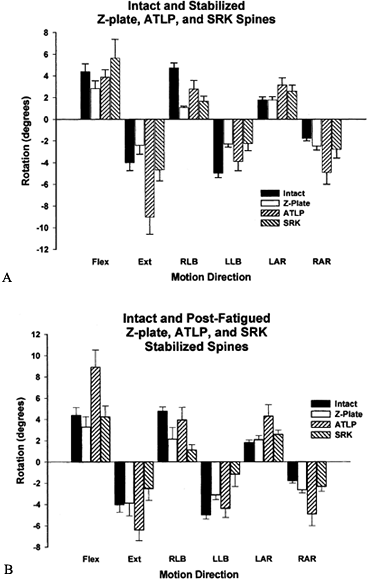 Figure 137.8.
Rotational data of the intact spine and the spine stabilized using
three devices: the Synthesis Anterior Thoracolumbar Locking Plate
(ATLP, Synthes, Palo, PA), the AcroMed Smooth Rod Kaneda System (SRK,
AcroMed Corp., Cleveland, OH), and Z-Plate (Sofamor-Danek, Inc.). A: Following stabilization, a significant difference was observed between the ATLP and both the SRK and Z-Plate in extension. B:
After cyclic testing, the SRK was found to provide significantly more
stability to the segment, as compared with the ATLP device, in flexion,
extension, lateral bending, and right axial rotation. The Z-Plate was
significantly more stable as well in flexion, extension, and axial
rotation.In flexion and extension, rigid posterior devices
provide a 70% reduction in motion across the L4–L5 level, compared with
the intact spine. Similar results were obtained for three different
systems which were loaded in lateral bending and axial rotation as well
(27).Pedicle screw systems are effective, at least initially,
in stabilizing the motion segment, irrespective of screw size, implant
shape, or other variables. This finding is not surprising in that
stainless steel and titanium implants are many orders of magnitude
stiffer than the bony and ligamentous components of an intact spine. As
a result, slight variations in the shapes and sizes of pedicle screw
devices are not likely to affect the stability of constructs to any
significant degree.Flexible restraints have been tried. The Graf system is
an extreme example of a flexible posterior system, in which bilateral
polyester tension bands span the vertebral pedicle screws (51).
After laminectomy, this system restored axial rotation to normal
stiffness levels. It also significantly decreased the range of motion
in flexion and extension and lateral bending. Flexible systems have not
proven successful in restoring stability to a severely destabilized
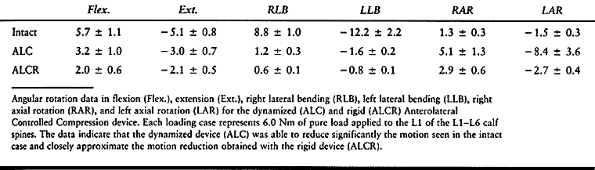
spinal segment such as after partial or total discectomy.The major concern with dynamized systems is whether they
can impart initial rigidity comparable to that of traditional systems
using plates, bars, and screws. Hitchon et al. (28)
evaluated the stiffness properties of one such anterior dynamized
system, the Anterolateral Controlled Compression (ALC) device (AcroMed,
Cleveland, OH). The implant can be applied as a dynamized device (ALC)
or can be attached rigidly (ALCR). Both applications produced the same
degree of stiffness in flexion, extension, lateral bending, and axial
rotation (Table 137.2). There seems to be no
loss of immediate stability using the implant as a dynamized device,
which may reduce long-term, deleterious effects due to stress shielding.![]() Table 137.2. Angular Rotations (Degrees)P.3629In a similar study (48), this
Table 137.2. Angular Rotations (Degrees)P.3629In a similar study (48), this
group compared the Segmental Spine Correction System (SSCS), which is a
pedicle hinged screw-rod system (Osteotech, Inc. Eatontown, NJ), with
its equivalent rigid screw system. The hinged screw allows 15° of
movement, at which point the hinge mechanism engages the screw shaft;
it then behaves like a rigid screw. The researchers showed a 65%
reduction of motion in flexion and extension and 90% reduction in
lateral bending across the destabilized segment for both devices when
compared with the intact spine.Interbody fusion cages have also been mechanically evaluated using cadaver models (42,52). Nibu et al. (42)
studied the stabilizing effect of implantation of the BAK (Spine Tech
Inc., Minneapolis, MN) interbody fusion device in human lumbrosacral
specimens (L5–S1). They found that range of motion was reduced by 46%
in flexion, 66% in lateral bending, and 40% in axial rotation after
implantation of the device as compared with the intact spine. However,
extension range of motion increased by 14% after implantation of the
device owing to the anterior approach, which required cutting the
anterior longitudinal ligament and the anterior annulus, which
compromises the stability in extension. -
Analytic modeling (15,19),
such as finite element (FE) analysis, is a valuable tool for
determining how implant and intraosseous loading patterns change with
varying parameters of the device design. FE modeling can also help
predict bone remodeling in response to the implant; therefore, it helps
in evaluating stress shielding. Goel et al. (13)
have generated osteoligamentous one-segment (L3–L4) and two-segment
(L3–L5) FE models of the intact lumbar spine. Using the L3–L4 model,
they simulated bilateral fusion using unilateral and bilateral plating,
and measured the magnitude and position of internal stresses in bone,
ligament, and the implants. They normalized their data to an intact
model. Bilateral plating models showed significantly reduced stresses
in cancellous bone. In a simulated consolidated fusion mass, there was
unloading of the cancellous bone, even after simulated removal of the
device. This model predicts that removal of the fixation would not
alleviate stress-shielding–induced osteopenia, which may be due to the
fusion mass itself.Models of unilateral plating revealed higher initial
trabecular bone stresses than were seen with bilateral plating.
However, the degree of initial stability was reduced. Thus, the best
appears to be a fixation system that allows the bone to bear greater
load as fusion proceeds, which would offer higher initial stability and
yet minimize the problem of long-term stress-shielding–induced bone
resorption.FE modeling (17) of newer
dynamic fixation systems shows that the load through the bone graft
increases 10% compared with the rigid systems. Thus, it seems that the
competing criteria can, in some part, be simultaneously satisfied with
these dynamized devices.FE modeling coupled with adaptive bone remodeling
algorithms has been used to predict temporal changes that may be
associated with interbody fusion devices. Grosland et al. (25) studied the BAK device (Fig. 137.9)
and showed that implantation of this interbody fusion device results in
hypertrophy of bone directly overlying and underlying the implant,
whereas lateral atrophy occurs due to the stress-shielding effects
associated with the relatively high stiffness of the implant. The model
also predicts that bone would be stimulated to grow into and around the
larger holes in the implant, resulting in sound fixation of the device. Figure 137.9.
Finite element (FE) modeling has proved to be an invaluable tool for
determining the changes in load sharing associated with device
implementation. The schematic depicts the implantation of an interbody
fusion device into a three-vertebrae FE model. This model has been used
to characterize not only the loading changes that will occur
immediately in the postoperative period but also as consolidation of
the graft proceeds.The value of FE modeling is that mapping of the stresses
and strains in bone, ligaments, and instrumentation can be obtained in
a relatively inexpensive and
P.3630
time-efficient
manner. In addition, it yields important predictive data concerning
temporal changes in bone in response to implantation of a device. It
also facilitates quick assessment of the relative advantages and
disadvantages of design iterations. Actual mechanical testing of
constructs is still necessary, from time to time, to validate
theoretical assumptions and confirm FE predictions. -
Animal studies provide real-time in vivo
data concerning the performance and associated biologic response to an
implant. Temporal changes in both the host biologic tissue and
associated instrumentation can be assessed with selective intermittent
sacrificing of the animals.The usefulness of these tests is best illustrated by the animal studies performed by McAfee et al. (32,33).
They investigated the effects of instrumentation on fusion
consolidation and peri-implant bone density in 63 canines. The data
confirmed a higher probability of achieving fusion when instrumentation
was used. Mechanical testing of the fusion sites after sacrifice (and
removal of all metal components) revealed that fusions achieved with
instrumentation were more rigid than those that occurred without
instrumentation. There was, however, an inverse correlation between
volumetric density of bone and rigidity of the implant, implying that
utilization of the implant resulted in an osteoporotic effect owing to
stress shielding. These findings could not have been predicted by the
FE models available at the time.The findings of animal models must be evaluated in terms
of their inherent limitations. Most animal studies involve quadrupeds;
thus, the loading imposed on the spinal instrumentation may not
represent the loading that it would experience in patients.For example, in the study mentioned earlier, McAfee et
al. used a complete corpectomy model, with the device spanning the
vertebrectomy space. In patients, one would expect a degenerated disc
or interbody bone graft between the vertebral bodies. Hence, in the
experimental model, the device assumed 100% of the load in contrast to
the load-sharing capabilities for which it was designed.The greatest value of animal studies is to provide
bioengineers and clinicians with data as to how the osseous and soft
tissues adapt to the altered loading environment produced by
instrumentation. They also demonstrate the impact of normal and altered
biology on the healing process.The biomechanical evaluation of spinal fusion and
stability has produced a large knowledge base that has allowed for the
design, development, and implementation of progressively more
sophisticated devices. The preceding methods are used to demonstrate
the safety and potential effectiveness of instrumentation. Of course,
the ultimate measure of efficacy of any system is based on
well-designed and selected studies.
segment work in unison to transmit loads and permit motion. If the
degenerative process, trauma, or any other factor affects an anatomic
component, changes in loading and motion patterns result. Modern
imaging techniques and clinical observations have adequately delineated
morphologic changes in certain spinal structures that may precede
degeneration of the spine. A surgeon combines this information with his
or her experience to assess instability and the need for surgery,
especially when conservative treatment options fail to produce
satisfactory results.
interbody, and fixation system must be approached from a biomechanical
perspective. The biomechanical data available can make the choice a
more informed one. On a short-term basis, rigid fixation devices (both
anterior
and
posterior) are capable of imparting stability to an injured or unstable
segment. The degree of stability imparted, at least in the physiologic
range of motion, does not vary significantly with the screw size,
implant shape, or other variables.
spinal fixation device to share a load with the maturing fusion mass
are essential for fusion to occur. If the load transferred through the
fusion mass is increased without sacrificing the rigidity of the
construct, a more favorable environment for fusion may be created.
Finally, although a host of experimental methods have enabled
researchers to evaluate initial device performance and failure
characteristics, the true measure of a device’s effectiveness can be
assessed only through properly designed clinical outcome studies.
scheme: *, classic article; #, review article; !, basic research
article; and +, clinical results/outcome study.
GW, Kuslich SD. Arthrodesis of the Lumbar Spine Utilizing a Rigid
Housing Containing Bone Graft—the BAK Interbody Fusion Method. In:
Thalgott JS, Aebi, eds. Manual of Internal Fixation of the Spine. Philadelphia: Lippincott-Raven Publishers, 1996:156.
GD, Abitbol JJ, Anderson DR, et al. Screw Fixation in the Human
Sacrum—an In Vitro Study of the Biomechanics of Fixation. Spine 1992;17:S196.
KW, Dewei Z, McAfee PC, et al. A Comparative Biomechanical Study of
Spinal Fixation Using the Combination Spinal Rod-plate and
Transpedicular Screw Fixation System. J Spinal Disord 1989;1:257.
VK, Grosland NM, Grobler LJ, Griffith SL. Adaptive Internal Bone
Remodeling of the Vertebral Body Following an Anterior Interbody
Fusion—a Computer Simulation. The 24th Annual Meeting of the
International Society for the Study of the Lumbar Spine, Singapore.
1997.
VK, Konz RJ, Chang H-T, et al. Hinged-dynamic Posterior Device Permits
Greater Loads on the Graft and Similar Stability as Compared to Its
Equivalent Rigid Device—a Three-dimensional Finite Element Assessment.
Submitted for publication, 1999.
VK, Lim TH, Gwon J, et al. Effects of Rigidity of an Internal Fixation
Device: A Comprehensive Biomechanical Investigation. Spine 1991;16:S155.
VK, Scifert JL, Grosland NM. Evaluation of Surgical Dynamics Rodding
System (SDRS) Using ASTM Standard Methodologies. (Personal
Communication), 1998.
T, Beach G, Cooke C, et al. Normative Database for Trunk Range of
Motion, Strength, Velocity, and Endurance with the Isostation B-200
Lumbar Dynometer. Spine 1991;16:15.
NM, Goel VK, Grobler LJ, Griffith SL. Adaptive Internal Bone Remodeling
of the Vertebral Body Following an Anterior Interbody Fusion—a Computer
Simulation. 24th Annual Meeting of the International Society for the
Study of the Lumbar Spine, Singapore, 1997.
JK, Chen J, Lim TH, et al. In Vitro Comparative Biomechanical Analysis
of Transpedicular Screw Instrumentations in the Lumbar Region of the
Human Spine. J Spinal Disord 1991;4:437.
K, Nightingale RW, Yu JR, et al. Strength and Stability of Posterior
Lumbar Interbody Fusion—Comparison of Titanium Fiber Mesh Implant and
Tricortical Bone Graft. Spine 1997;22:1181.
IH, Khazim R, Woodside T. Anterior Vertebral Body Screw Pullout
Testing. A Comparison of Zielke, Kaneda, Universal Spine System, and
Universal Spine System with Pullout-resistant Nut. Spine 1998;23:908.
TO, McLain RF, Yerby SA, et al. The Effect of Pedicle Morphometry on
Pedicle Screw Loading in Unstable Burst Fractures: A Synthetic Model. Spine 1997;22:246.
TO, McLain RF, Yerby SA, et al. Effects of Pedicle Screw Insertion
Techniques on Pedicle Screw Bending Moments: A Biomechanical Analysis. Spine 1999;24:18.
RF, McKinley T, Sarigul-Klijn N, et al. The effects of Cancellous Bone
Quality on Pedicle Screw Loading in Axial Instability: A Synthetic
Model. Spine 1997;22:1454.
K, Panjabi MM, Oxland T, Cholewicki J. Multidirectional Stabilizing
Potential of Bak Interbody Spinal Fusion System for Anterior Surgery. J Spinal Disord 1997;10:357.
I, White AA, Edwards WT, Hayes WC. A Biomechanical Analysis of the
Clinical Stability of the Lumbar and Lumbosacral Spine. Spine 1982;7:374.
JL, Sairyo K, Goel VK, et al. Stability Analysis of an Enhanced Load
Sharing Posterior Fixation Device and Its Equivalent Conventional
Device in a Calf Model. Spine 1999;24:2206.
P, DeMauroy JC, Dran G, et al. Reciprocal Angulation of Vertebral
Bodies in a Sagittal Plane: Approach to References for the Evaluation
of Kyphosis and Lordosis. Spine 1982;7:335.
RH, Shea M, Edwards WT, et al. A Biomechanical Study of the Fatigue
Characteristics of Thoracolumbar Fixation Implants in a Calf Spine
Model. Spine 1992;17:S121.