
separate intracapsular articulations. These are highly congruent joints
with multiplanar, noncollinear surfaces that make imaging difficult.
The relatively small amount of overlying soft tissue and the ease of
positioning, however, aid in imaging efforts. As with other joints,
multiple imaging tools are available. The most commonly used include
plain radiographs, computed tomography, and magnetic resonance imaging.
Arthrography is often a useful adjunct to these studies, but is less
commonly used alone. Ultrasound may be helpful in some situations where
dynamic images are required. Plain tomography and xeroradiography have
largely been replaced by newer, better studies and are mentioned here
for the sake of completeness.
the elbow, including appropriate techniques and parameters. Guidelines
to assist in choosing the appropriate test for specific clinical
situations will be discussed.
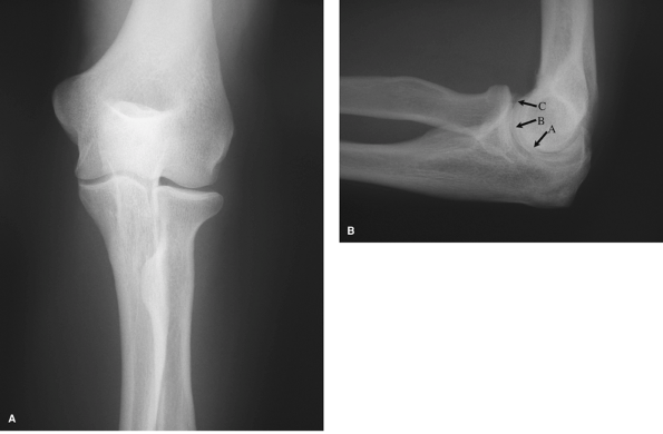
demonstrates the distal humeral articular surface, medial and lateral
epicondyles, radial head and neck, and most of the proximal ulna,
excluding clear views of the coronoid and olecranon processes. The
ulnohumeral and radiocapitellar joint spaces are well seen and can
demonstrate widening or narrowing depending on the clinical condition.
The lateral radiograph (Fig. 48-1B) clearly
shows the coronoid and olecranon processes, as well as the associated
fossa. The radial head overlies the coronoid, but should still allow
adequate visualization of both structures. Adequacy of the lateral view
can be determined by the target sign of three concentrically larger
circles seen in the distal end of the humerus. These rings represent,
from inside out, the minimum dimension of the trochlea, the capitellum,
and the medial rim of the trochlea. Malrotation by as little as 5
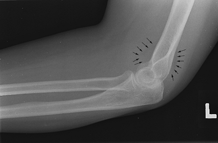
degrees will disrupt this appearance. Anterior and posterior fat pads
can be seen in situations of intra-articular distension (Fig. 48-2). The supinator fat stripe can be displaced by swelling associated with radial head fractures.
an appropriately sized image receptor. The arm is parallel with the
plate, and the forearm is in supination. The beam is directed
perpendicular to the midpoint of the elbow joint, and the joint is
centered on the film. The lateral view is obtained with the shoulder
abducted to 90 degrees, the arm parallel to the plate, and the forearm
in full supination. The beam is directed perpendicular to the elbow
joint, or ideally at a 7-degree caudal angle to replicate the carrying
angle.
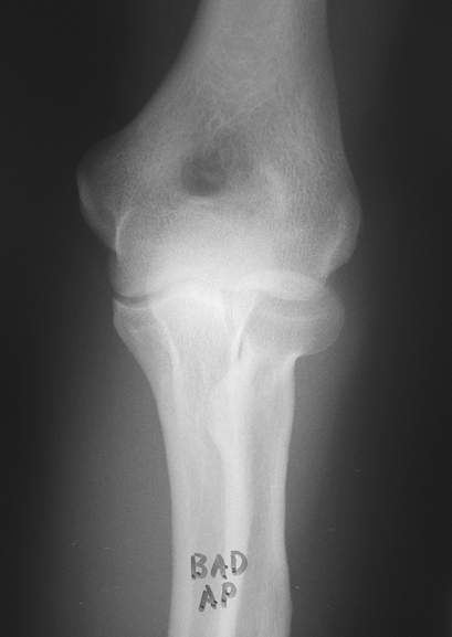
A single AP view obtained through a flexed elbow is of little value. In
this situation, two views—an AP view of the proximal forearm and an AP
view of the distal humerus—should be obtained.
flat and the elbow joint centered on the plate. A greater degree of
flexion deformity will require increased kilovoltage (Kvp) to allow
adequate penetration to demonstrate bony detail. The humerus view is
obtained with the distal humerus flat on the plate with the elbow
centered. The forearm should be supported for comfort. The beam is
directed perpendicular to the elbow joint.
features of the elbow anatomy. The internal (medial) oblique view
improves visualization of the trochlea, olecranon, and coronoid. The
external (lateral) oblique view improves visualization of the
radiocapitellar joint, radioulnar joint, medial epicondyle, and
coronoid tubercle.
positioned initially as for an AP view. The arm is then rotated
internally 45 degrees. The beam is directed perpendicular to the plate
and elbow joint. The external oblique view is obtained by rotating the
arm externally 45 degrees.
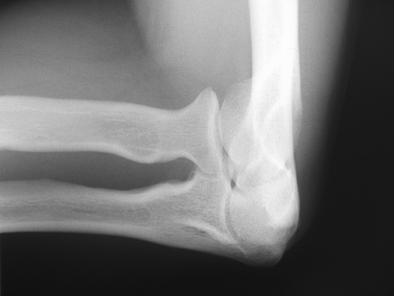
head view and lateral radial head rotation positions. The radial head
view (Fig. 48-4) minimizes the overlap of the
radial head and coronoid, improving visualization of radial head and
capitellar pathology. Visualization of the fat pads is enhanced as
well. The lateral rotation positions demonstrate
the
radial head in profile throughout its full available arc of motion. The
radial tuberosity is the most obvious indicator of the position of
forearm rotation. The coronoid is viewed without superimposition with
the coronoid-trochlea position.
 |
|
Figure 48-1 A: Anterior-posterior (AP) view of the elbow in full extension. B: Lateral view of the elbow. Note concentric circles representing, from the center out, (A) trochlear sulcus, (B) capitellum, and (C) medial wall of the trochlea.
|
elbow in the standard lateral position and angling the beam 45 degrees
cephalad, parallel to the long axis of the humerus. The lateral
rotation positions require standard lateral position of the elbow and
perpendicular beam position. The forearm is then positioned in
hypersupination, midsupination, midpronation, and hyperpronation. The
coronoid-trochlea image is obtained by positioning similar to the
radial head view, but angling the beam 45 degrees caudal.
 |
|
Figure 48-2 Lateral view of the elbow with occult radial head fracture. Note the elevated anterior and visible posterior fat pads (black arrows).
|
These include the axial olecranon projection view, which enhances the
visualization of the olecranon margins and associated spurs; also, the
cubital tunnel view demonstrates any bony abnormalities or encroachment
on the ulnar nerve in the cubital tunnel.
proximal dorsal forearm flat against the plate, full supination, and
maximal elbow flexion with the humerus overlying the forearm. The beam
is angled 20 degrees toward the hand along the long axis of the
forearm. The cubital tunnel view is obtained by placing the humerus
flat on the plate, maximal flexion of the elbow, and 15 degrees of
external rotation of the arm. The beam is directed perpendicular to the
plate and elbow joint.
evaluation of valgus instability. This technique can minimize
apprehension but requires patient relaxation and cooperation to avoid a
false-negative result. Gravity-induced valgus instability is
demonstrated by widening of the joint space of the medial side of the
joint.
the arm abducted 90 degrees away from the side. The arm is externally
rotated, the thumb pointing to the floor. The
elbow
is flexed 15 degrees. The plate is oriented vertically and placed
dorsal to the elbow. The beam is directed horizontally, perpendicular
to the elbow joint.
 |
|
Figure 48-3
Poor-quality anterior-posterior view of the elbow. Flexed position creates overlap of structures and inadequate visualization of bony detail. |
systematically reviewed and irregularities noted, and when indicated,
additional views or studies obtained. On all views the radial head
should line up with the capitellum. The radiocapitellar and ulnohumeral
joint space should be symmetric on the AP view; the coronoid-trochlear
and the olecranon-trochlear joint spaces should be symmetric on the
lateral view. Visualization of the anterior and posterior fat pads on
the lateral radiograph (Fig. 48-2) is a
reliable sign of intra-articular fluid collection, most common with
trauma or inflammation. Occult fracture should be sought when
accompanied by a history of trauma. Finally, for all of the utility of
plain radiographs, they still present a two-dimensional representation
of a three-dimensional structure. The ability of computed tomography
and magnetic resonance imaging to present the elbow anatomy in three
dimensions underscores their importance as an adjunct to the diligent
history taking and careful physical examination in the diagnosis of
elbow pathology.
 |
|
Figure 48-4 Radial head view. Overlap of the coronoid is minimized, improving visualization of the radial head and capitellum.
|
of plain tomography in this country. CT has the advantage of clearer
images and multiplanar views over plain tomography, although metal
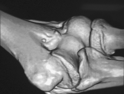
artifact remains a limitation. Three-dimensional rendering of the elbow
joint is possible as well (Fig. 48-5). The
decreased slice thickness and helical image acquisition of the newest
scanners provide for improved clarity of reconstructed images.
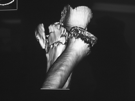
Nonaffected bones can be digitally subtracted to allow improved
visualization of the involved area (Fig. 48-6).
This is especially helpful in complex coronoid fractures as well as for
preop planning for elbow malunion surgery. The injection of
radio-opaque dye with or without air (single- or double-contrast
arthrogram) provides more sensitive evaluation of cartilaginous loose
bodies and the status of the articular cartilage. The author believes
that
CT
arthrogram provides the best evaluation for loose bodies in the elbow
with catching and/or locking, although other literature demonstrates no
advantage of CT arthrogram over MRI evaluation.
 |
|
Figure 48-5 Three-dimensional reconstruction of the elbow joint. Coronoid spur and anterior loose body are well seen.
|
 |
|
Figure 48-6
Three-dimensional reconstruction of the elbow joint with digital removal of the humerus. The comminuted coronoid fracture is clearly seen. The abnormality of the radial head represents artifact rather than radial head/neck fracture. |
highest-quality images of the soft tissues about the elbow. As more
imaging protocols emerge, the utility of this technology broadens. MRI
should be used, however, to test a specific hypothesis, developed by
the history and clinical examination, rather than as a “fishing
expedition” on any and all painful elbows. The nature of the suspected
problem determines the positioning and imaging protocols used to
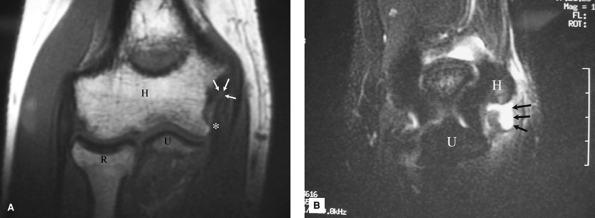
evaluate the elbow. Common indications include collateral ligament
injuries (Fig. 48-7A, B), osteochondritis
desiccans, and partial biceps injuries. MRI is not usually required in
complete biceps tears with retraction or in the setting of traumatic
fracture/dislocations where significant soft tissue injury can be
assumed. Some have advocated the use of MR arthrogram to improve the
sensitivity of collateral ligament injury diagnosis. Imaging can be
performed safely with implanted metallic plates and screws, although
scatter artifact limits image clarity.
 |
|
Figure 48-7 A: T1, spin echo, coronal image. Humerus (H), ulna (U), and radius (R). The low-signal, anterior bundle of the medial collateral ligament (MCL) (asterisk) is detached from its origin on the medial epicondyle; there is intermediate signal intensity (white arrows) seen at the site of the origin of the MCL indicating discontinuity. B: T2, fast spin echo with fat suppression, coronal image. Humerus (H), ulna (U). High-signal fluid (arrows) seen exiting through the tear of the origin of the MCL into surrounding soft tissues.
|
Fluid and edema appear bright on the T2-weighted images, indicating
soft tissue injury. Avascular bone appears dark on T1 images surrounded
by the brighter signal of the normal cancellous bone. A fast spin echo,
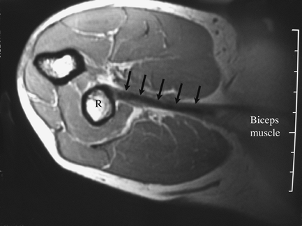
T2-weighted image with fat suppression is used to best image the
collateral ligaments (Fig. 48-7B). Special positioning improves the image acquisition in patients with distal biceps injuries (Fig. 48-8).
ligaments, muscles, peripheral nerves, and joint structures. Advantages
to ultrasound include accessibility, low cost, portability, and lack of
contraindications (unlike MRI). In several specific applications, elbow
ultrasound is the preferred imaging method, even over MRI. One such
application is dynamic imaging of the elbow, where abnormalities may be
present only with specific joint movements or
position.
Examples include ulnar nerve dislocation and snapping triceps syndrome,
which occurs with elbow flexion. An additional dynamic examination of
the elbow under ultrasound observation is assessing injury to the
anterior bundle of the ulnar collateral ligament with valgus stress
applied to the elbow. Another advantage of ultrasound is evaluation of
soft tissues superficial to metal hardware free of artifact. Peripheral
nerves can also be efficiently evaluated with ultrasound, such as
evaluation for the radial nerve injury after plate fixation of a
humeral diaphyseal fracture.
 |
|
Figure 48-8 MRI of the distal biceps tendon (arrows)
using the flexion, abduction, supination (FABS) view. Note that the entire length of the tendon is well visualized on one image, from the muscle belly (labeled) to the radius (R). |
plain radiographs. Additional radiographic images should be included as
indicated for specific pathology (Table 48-1).
Evidence of associated fracture should be sought in all cases of elbow
dislocation, as this affects treatment and prognosis. Thin-cut CT with
multiplanar reconstructions are especially helpful in the evaluation of
coronoid and capitellum fractures, as well as intracapsular distal
humerus fractures. The CT images often demonstrate more significant
pathology than suspected on plain films. Three-dimensional
reconstructions with digital subtraction of uninvolved bony structures
allow excellent visualization of complex intra-articular pathology. MR
imaging provides excellent soft tissue definition, but is rarely
indicated in high-energy trauma. Certain soft tissue injury patterns
are common, such as lateral ulnar collateral ligament injury associated
with radial head and coronoid fracture, and should be anticipated. MRI
has increased utility in the evaluation of musculotendinous and
ligamentous trauma, such as acute throwing injuries and biceps tendon
pathology. Special imaging protocols have been developed to improve
diagnostic accuracy.
|
TABLE 48-1 Recommended Studies I: Trauma
|
||||||||||||
|---|---|---|---|---|---|---|---|---|---|---|---|---|
|
||||||||||||
case of acute instability, the above trauma recommendations apply.
Chronic instability is largely a clinical diagnosis. MRI is less
sensitive in delineating attenuated ligamentous structures unless there
is a superimposed acute on chronic injury. Gravity stress radiographs
may confirm the diagnosis of valgus instability. In cases of
posttraumatic chronic instability, CT images may clarify the competence
of key structures such as the anterior and medial coronoid and radial
head. Evaluation of the joint with real-time fluoroscopy before
surgical procedures can be invaluable in clarification of instability
patterns Examination of the awake patient to determine patterns of
instability can be unreliable. It is highly recommended that all
patients with a question of instability undergo a fluoroscopic
examination after general anesthesia but prior to sterile surgical
preparation of the patient.
contracture, bony block, or most commonly, both causes. Plain films
demonstrate bone causes such as heterotopic ossification (HO), loose
bodies, or joint incongruity. CT scanning provides three-dimensional
visualization of the bony abnormality and can be helpful in
preoperative planning. Certain patterns of heterotopic bone formation
are common. Posttraumatic HO typically occurs in the anterior lateral
aspect of the joint. In cases of neuromuscular or burn HO, the
posterior medial joint is most commonly involved. The ulnar nerve may
be completely encased in bone;
nevertheless,
surprisingly, it almost always functions normally. CT images may
clarify whether the ankylosis is complete or incomplete; in the latter
case removal is simplified. MRI is of limited value in cases of soft
tissue contracture and is not recommended.
|
TABLE 48-2 Recommended Studies II: Nontrauma
|
||||||||||||||||
|---|---|---|---|---|---|---|---|---|---|---|---|---|---|---|---|---|
|
||||||||||||||||
The traumatized elbow is discussed above. In young athletes,
osteochondritis dissecans (OCD) and apophysitis should be considered.
These may be seen on plain x-ray films (contralateral images should be
obtained), but MRI may be needed in early or subtle presentations. MRI
or bone scan will demonstrate stress fractures, not seen on plain x-ray
views. In cases of painful catching or locking, with or without
limitation of motion, the author uses CT arthrogram to evaluate for
loose bodies if the plain films are inconclusive. If the CT is
positive, loose body removal is recommended; if negative, a symptomatic
plica may be the cause of the symptoms. Throwers and other overhead
athletes with medial elbow pain rarely exhibit gross instability. A
medial stress view may show widening of the medial joint. An axial
olecranon view may show posterior medial osteophytes associated with
valgus extension overload syndrome. Finally, MRI may demonstrate medial
collateral ligament (MCL) pathology or flexor pronator mass
inflammation. Ulnar nerve instability may cause medial-sided pain. This
is well evaluated by ultrasound. Ultrasound is also useful for
demonstrating the snapping triceps syndrome, owing to the dynamic
nature of the image acquisition. Additional imaging is rarely indicated
in clinical cases of medial or lateral epicondylitis. Plain films may
show periosteal reaction at the involved epicondyle. MRI adds little to
the diagnosis or treatment of this condition. Avascular necrosis of the
distal humerus is occasionally seen in patients on high-dose steroids,
with alcoholism, or other lipid metabolism disorders. This may be seen
on plain films, but often late in the course. MRI will demonstrate
low-signal intensity of avascular bone on T1 images before changes can
be detected on plain radiographs. Osteoarthrosis and inflammatory
arthropathies are typically well visualized on plain x-ray films. CT is
occasionally helpful to determine the extent of joint space
involvement. Anterior cubital fossa pain, especially with resisted
flexion and supination, may indicate a partial biceps injury. MR
imaging can identify partial biceps injury or associated pathology.
Ultrasound can provide similar information, often at lower cost, but
the results are more operator dependent.
high-resolution images of the bone and soft tissue anatomy of the
elbow. Plain radiographs remain the appropriate initial choice in the
diagnosis of many conditions and may indicate the need for confirmatory
studies. MR imaging is most useful for the imaging of the soft tissues,
whereas CT best defines the bony anatomy. Fluoroscopy and ultrasound
provide motion images in real time, improving the diagnosis of dynamic
conditions such as snapping triceps and instability patterns. All of
these studies provide invaluable information to supplement, rather than
replace, a careful history and physical examination for the diagnosis
of complex elbow problems.