
specialized, antegrade, femoral, intramedullary nails designed to
provide fixation into the femoral head and neck for selected, complex,
proximal-femoral fractures. Reconstruction nails are a subset of
cephalomedullary nails that are distinguished by two proximal
interlocking screws that permit sliding lag-screw fixation into the
femoral head, which enhance rotational stability in the proximal femur,
and distal interlocking screws, which ensure rotational and axial
stability. In addition, the geometry of the nail is altered throughout
its length with variations in cross section to maximize nail strength
and to minimize its stiffness. This modulation in cross section is
especially important in the subtrochanteric region where fatigue
stresses are relatively high. All reconstruction nails have an anterior
bow to facilitate nail insertion.
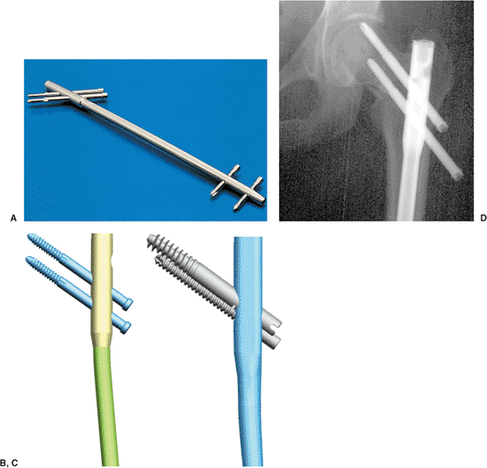
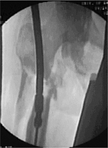
Reconstruction Nail (Smith & Nephew, Memphis, TN) introduced in
1986. It was a closed-section implant designed for a piriformis entry.
The nail was calibrated to approximate 95% of the intact bending
stiffness and 50% of the rotational stiffness in the intact femoral
diaphysis. The proximal cross section was modified to enable a higher
fatigue life in the subtrochanteric region and was 15 mm in diameter in
this area with the diaphyseal diameter available in 12, 13, and 14 mm (Fig. 20.1).
This original design was frequently referred to as a “second-generation
interlocking nail.” Subsequently, newer generations of reconstruction
nails have been introduced by various manufacturers. They vary in their
proximal geometries, diameter, cross-sectional design, and proximal
screw geometries (see Fig. 20.1A–C).
can be used to stabilize injuries from the femoral neck to
approximately 4 cm above the knee. Reconstruction nails were originally
designed for subtrochanteric femoral fractures, pathologic femoral
fractures, and
selected,
ipsilateral, femoral neck and shaft fractures. Segmental fractures of
the femur, in which the proximal fracture extends into the upper
femoral metaphysis, are also good indications for reconstruction nails.
Reconstruction nail techniques are also used for deformity correction
and stabilization of malunions, nonunions, and failed plate fixation of
subtrochanteric femur fractures.
 |
|
Figure 20.1. A.
Second-generation reconstruction nail: Russell-Taylor. Fifteen millimeter, proximal, cross section with 135-degree angle-reconstruction screws. B. Third-generation reconstruction nail: TriGen TAN for reconstruction or standard mode. Proximal cross section decreased to 13 mm with screws at 130 or 135 degree angles. Titanium alloy material. C. Fourth-generation reconstruction nail: TriGen Intertan reconstruction nail. Rotationally stabilized, compression, screw mechanism with enhanced proximal metaphyseal fill design. Titanium alloy material. D. Z-effect. Note rotationally unstable neck component leading to medial migration and intra-articular penetration of proximal screw and backing out of inferior reconstruction screw. |
of first choice for diaphyseal fractures of the femur because of the
complexity of targeting and placing screws in the femoral head.
However, in pathologic fractures and osteoporotic femoral fractures,
reconstructions nails are often recommended to prevent subsequent
femoral-neck fractures. Reconstruction nailing is contraindicated in
children with open, proximal, physeal plates.
entry portals should be avoided in displaced femoral-neck fractures and
four-part intertochanteric fractures due to their propensity for
fixation loss with rotation and varus loading. This so-called
“Z-effect” results in loss of proximal screw fixation with intrusion of
the cephalic screw into the joint space and subsequent backing out of
the inferior head and neck screw (see Fig 20.1D).
In an effort to minimize fracture deformity and loss of reduction or
fixation, third-generation reconstruction nails, such as the TriGen
Trochanteric Reconstruction Nail (Smith & Nephew, Memphis, TN) for
use with trochanteric entry portal, have been designed.
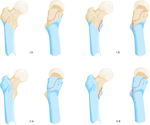
subtrochanteric femur fractures based on the presence or absence of
fracture involvement of the lesser trochanter/medial calcar and greater
trochanter (piriformis fossa) (Fig. 20.2).
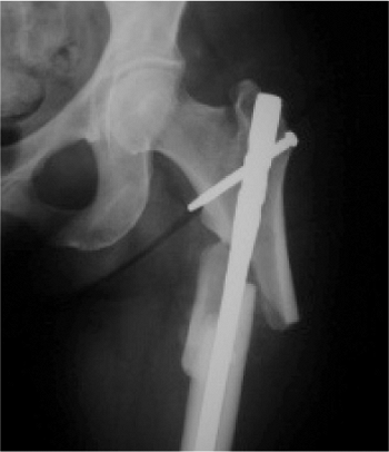
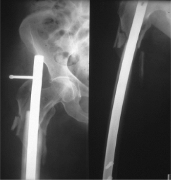
Fractures involving the lesser trochanter but without extension into
the greater trochanter (Russell-Taylor IB), are perhaps the best
indication for a piriformis-portal reconstruction nail (Fig. 20.3).
Historically, group 1 Russell-Taylor fractures were considered optimal
for intramedullary nail techniques with piriformis portal approaches,
and group 2 Russell-Taylor fractures were most often treated with plate
and screw techniques. Now, almost 20 years since the first
reconstruction nail was introduced, the techniques of nailing have
undergone such significant improvements that many Russell-Taylor group
II fractures can be addressed with an intramedullary hip screw (IMHS)
or third-generation trochanteric reconstruction nails.
 |
|
Figure 20.2.
Diagram of components of Russell-Taylor IB subtrochanteric pattern with greater trochanter intact and lesser trochanteric fracture. |
 |
|
Figure 20.3. Subtrochanteric fracture with intact greater trochanter and fracture of the lesser trochanter.
|
trauma in younger patients and lower-energy falls in the elderly. With
high-energy subtrochanteric fractures, associated injuries are found in
up to 50% of patients. Open subtrochanteric fractures are rare, as are
compartment syndromes, but both of these complications increase the
morbidity of the injury if rapid assessment and treatment are not
instituted.
have hip or thigh pain, an external rotation deformity, and angulation
in the proximal thigh if the extremity is not splinted. Frequently
(depending on the mechanism and time elapsed since injury), ecchymosis
and swelling of the thigh are apparent. Neurological or vascular
injuries are uncommon with subtrochanteric fractures unless they are
the result of penetrating trauma.
(AP) and lateral views of the entire femur including the hip and knee.
The radiographs should be carefully inspected to rule out
intra-articular propagation of fractures or concomitant degenerative
disease. In patients with complex fracture patterns or extensive
comminution, radiographs of the uninjured femur may be used to estimate
nail diameter and length. Radiographic templates for planning an
operation in which reconstruction nails are available from most of the
implant manufacturers.
fracture site must be obtained with skeletal traction before closed
nailing. Failure to restore length may lead to excessive intraoperative
traction and resultant pudendal or sciatic nerve injuries.
determine whether the fracture extends into the greater trochanter and
piriformis fossa. With the widespread use of rapid CT scanners in
trauma units, inclusion of proximal femur scans of patients with hip
injuries is an excellent method for determining trochanteric
involvement. In patients with extension of the fracture above the
lesser trochanter, a coronal split in the proximal fragment is
frequently present. This may result in comminution of the proximal
fragment with loss of the entry portal during reaming and nailing. In
these cases, reconstruction nailing may be contraindicated. If the
fracture is nailed, an open reduction of the proximal fragment with
provisional stabilization of the trochanteric region via reduction
forceps is strongly advised.
ranging from 10 to 16 mm in diameter with lengths between 240 and 500
mm. The nails are right-sided and left-sided, to compensate for the
anteversion of the femoral neck in relation to the shaft axis in the
coronal plane. To facilitate screw entry into the femoral head, the
proximal locking-screw holes are oriented anteriorly 8 to 15 degrees in
relation to the distal screw holes. When
using
reconstruction nails, surgeons typically also use two sliding lag
screws proximally to maximize purchase in the femoral head and to
minimize rotation of the proximal fragment. These lag screws vary
between 5 and 8 mm in diameter.
in relation to the nail, spacing between the proximal screws, and their
enclosed diameter are important in implant selection. Nail neck-shaft
angles vary from 125 to 135 degrees. Higher-angle designs maximize
sliding capabilities but are difficult to insert in hips with a
relative varus position. Lower-angle designs have higher stresses and
less sliding capability but are easier to insert. Most designs are
moving toward a compromise of 130 degrees. In most designs,
reconstruction nails have an effective spread between the two proximal
screws of 11 to 21 mm. Measurement of the preoperative radiographs is
necessary to understand the patient’s neck-shaft angle and to plan
screw spacing and final nail position. Reconstruction nails are
typically enlarged proximally to compensate for the higher stresses in
the subtrochanteric region. This must be recognized in preoperative
planning because additional reaming of the proximal fragment is
necessary in relation to the diaphyseal reaming. Distal interlocking
screws are usually 4.5 to 6.4 mm in diameter and vary from
full-threaded to partially threaded designs.
of the patient and the extent of femoral comminution. To minimize the
risk of nail failure, the largest implant suitable for the patient
should be used such that excessive amounts of cortical bone are not
removed. Even when interlocking is used, the nail should fill the
medullary canal at the isthmus to minimize translational deformities.
For maximal stability, static locking is recommended in acute
fractures. The nail tip should extend into the distal femoral
metaphysis to avoid stress risers in the diaphyseal area and facilitate
distal interlocking.
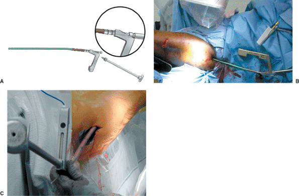
technique (MINIT) in conjunction with the TriGen nail system with both
piriformis and trochanteric nail designs. MINITs are designed to
protect soft tissues and preserve bone; they are not just percutaneous
techniques. They emphasize precise portal placement and preservation,
as well as trajectory control, to avoid malreductions and damage to the
proximal femur.
reconstruction nailing because it is familiar to most surgeons and
allows adequate visualization of the hip in both AP and lateral views,
which is critical to successful implantation of the device. The lateral
decubitus position, which allows better visualization of the entry
portal than does the supine position, is helpful with revision nailing,
especially in patients who have experienced previously failed nailings
due to incorrect entry portals. It is also helpful with reverse
obliquity fractures because the lateral position reduces the medial
translation of the shaft component.
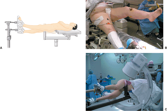
limb and trunk are abducted while the affected extremity is adducted.
To reduce the distal shaft fragment to the proximal fragment, the
affected hip is flexed 15 to 35 degrees with maintenance of the
heel-to-toe relation (Fig. 20.4). Traction is
applied after flexion positioning through the foot holder attached to
the fracture table or through a skeletal pin in the distal femur or
proximal tibia. Rotational alignment of the proximal fragment is
determined with the image intensifier. The distal fragment is rotated
to align with the proximal fragment (a true lateral of the knee is
confirmed with overlapping of both femoral condyles). The surgeon must
remember that femoral-neck anteversion in adults averages 15 degrees in
Caucasian populations, but it may be up to 30 degrees in Asian
populations. In the supine position, the leg will usually lie in 0 to
15 degrees of external rotation when the distal fragment is correctly
rotated. In the lateral decubitus position, the foot and leg should be
internally rotated approximately 15 degrees to match the tendency of
the femoral head to orient toward the floor in a pendulum-like fashion.
 |
|
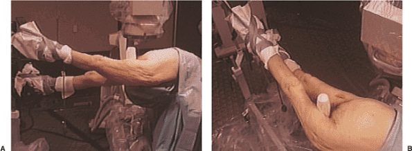
Figure 20.4. A,B.
Supine position with affected extremity in foot traction, adducted for facilitation of entry portal, flexed approximately 15 degrees at the hip, and with knee extended. |
crest, including the buttocks and lateral thigh, distally to below the
knee. The image-intensifier arm should be covered with a sterile
isolation drape. A first-generation cephalosporin (or substitute in the
patient with penicillin allergies) is administered. Vancomycin or an
aminoglycoside is added if the fracture is open. Usually cephazolin (1
g by IV) is continued for 24 to 48 hours after surgery in patients with
closed fractures. Reconstruction nailing of open fractures should be
performed only after appropriate debridement and irrigation of the open
fracture wound. Delayed nailing is recommended for grade IIIB
fractures. Reprepping and redraping of the extremity are required to
minimize cross contamination at the nail insertion site.
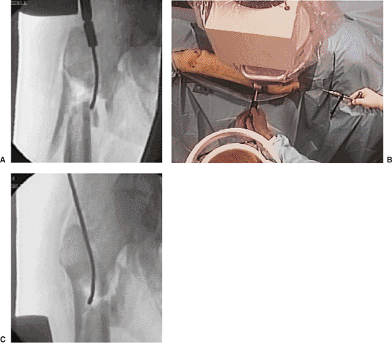
The fascia of the gluteus maximus is incised, and the muscle is opened
in line with its fibers. The subfascial plane of the gluteus maximus is
identified, and the trochanteric or piriformis fossa is palpated.
 |
|
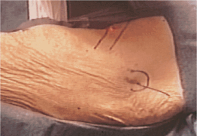
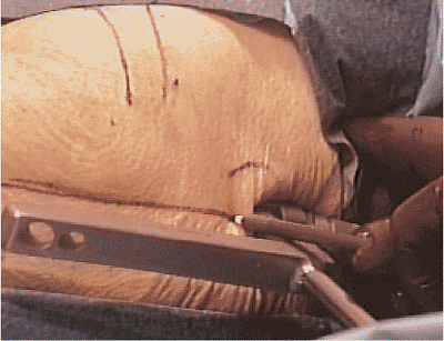
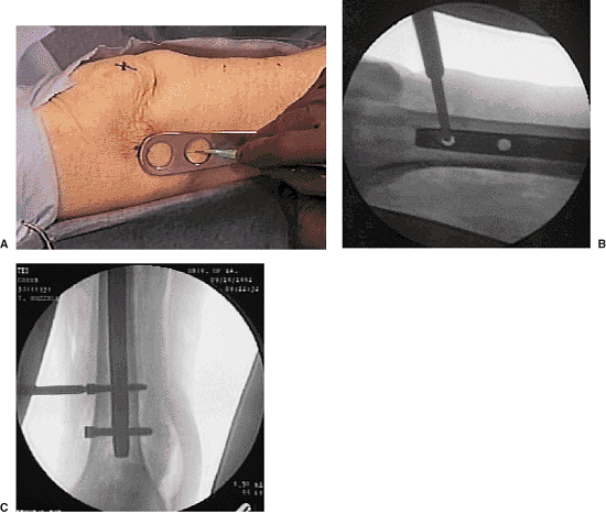
Figure 20.5. Skin incision.
|
 |
|
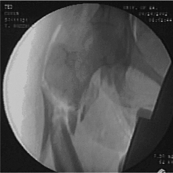
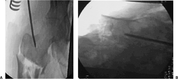
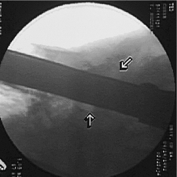
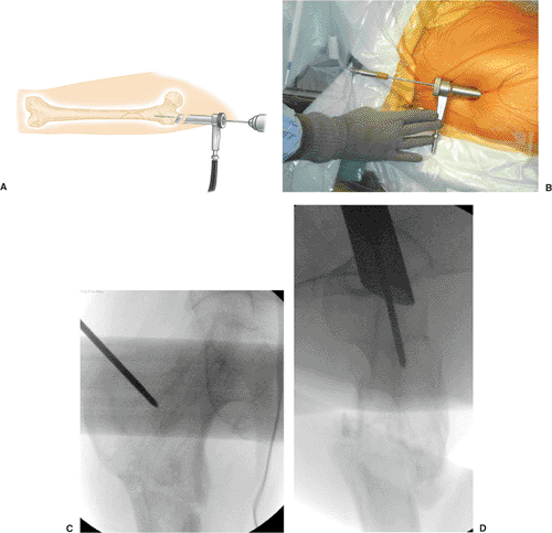
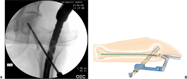
Figure 20.6. A,B. Tip-threaded guide pin inserted into piriformis fossa, centered on lateral view.
|
crucial. Incorrect starting points can lead to angular deformities. For
conventional, reamed, piriformis, intramedullary nailing, the correct
starting point is in the piriformis fossa. However, for reconstruction
nailing, the portal of entry is slightly anterior to the fossa. Because
the femoral neck arises from the anterior portion of the proximal
femur, moving the starting point 3 to 4 mm anteriorly facilitates
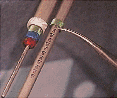
proximal screw insertion. A 3.2-mm threaded guide pin is inserted at
the entry site and confirmed by fluoroscopy to be in the midline of the
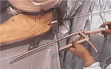
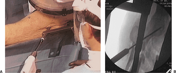
femur in both AP and lateral views (Fig. 20.6). The entry portal is enlarged with the cannulated reamer over the guide pin (Fig. 20.7).
If the proximal femoral fragment is flexed, externally rotated, and
adducted to such a degree that the entry portal cannot be visualized,
then the surgeon should manipulate the proximal fragment with a pointed
reduction forceps or percutaneously inserted Schanz pin into a position
such that the AP projections show a normalized fragment.
 |
|
Figure 20.7. A,B. For correct entry portal, the guide wire should be overreamed with an 8-mm cannulated rigid reamer.
|
 |
|
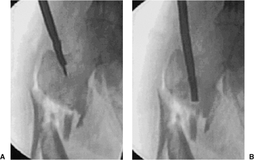
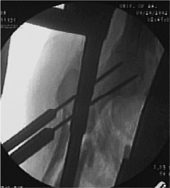
Figure 20.8. A,B. A 3.2-mm guide wire is inserted into fracture site. The tip of wire is bent to facilitate fracture reduction.
|
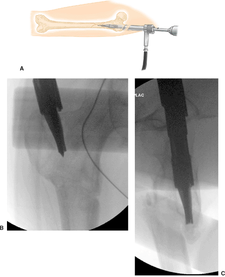
ball-tipped guide wire is bent at its tip. The wire is advanced to the
level of the fracture with the curve opposing the medial cortex. Its
position is confirmed within the femur by AP and lateral views taken
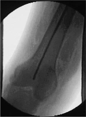
with the image intensifier (Fig. 20.8). The proximal fragment is reduced to the distal fragment manually or with an internal fracture-alignment device (Fig. 20.9).
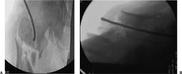
The guide wire is advanced into the center of the distal fragment until
its tip reaches the distal femoral-epiphyseal scar. The position of the
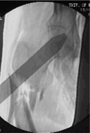
guide wire is verified within the femur by image intensification (Fig. 20.10).
at least 1.0 mm more than the proposed nail diameter. In patients with
a large anterior bow of the femur, as seen on lateral radiographs, or
fracture extension into the distal one fourth of the femur, the surgeon
should overream 1.5 to 2.0 mm larger than the nail diameter. The final
reamer diameter should be verified with the reamer template before nail
selection and insertion. A nail that has a larger diameter than the
last reamer used should never be inserted. The proximal 8 cm of the
femur is reamed to 15 mm in diameter with progressive reamers (starting
with a 9-mm reamer) to accommodate the enlarged proximal end of most
reconstruction nails (Fig. 20.11). Because the
proximal fragment must be reamed substantially, the surgeon must avoid
the destruction of the proximal entry portal that can be caused by
eccentric reaming, which usually occurs during insertion of the reamer
and during its extraction. To avoid this complication, a slotted hammer
or other instrument to direct a medial force on the reamer shaft should
be used during insertion and extraction (Fig. 20.12).
by two separate methods: the guide-wire method or the nail-length
gauge. With either method, residual distraction at the fracture site
must be eliminated. In the guide-wire method, the distal end of the
guide wire is placed between the proximal pole of the patella and the
distal femoral-epiphyseal scar, while a second guide wire is overlapped
to the portion of the reduction guide wire extending proximally from
the femoral entry portal. To determine nail length, the length (in mm)
of the overlapped guide wires is subtracted from 900 mm. In another
alternative, a nail-length ruler is placed on the skin of the anterior
thigh (unaffected femur preoperatively; affected femur
intraoperatively) with its distal end between the proximal pole of the
patella and the distal femoral-epiphyseal scar. The c-arm is moved to
the proximal end of the femur, and the correct nail length is read
directly from the stamped measurements on the nail-length ruler.
wire to maintain fracture reduction while the ball-tip guide wire is
replaced with a nail-driving wire (without ball tip). The medullary
exchange tube is removed. With the Russell-Taylor system, the reaming
guide rod and nail driving rods are identical, so placement of the
medullary exchange tube is unnecessary.
 |
|
Figure 20.9. A–C.
Combination of external force, internal guide, and adjustment of fracture table into abduction to accomplish fracture reduction. |
 |
|
Figure 20.10. Guide wire inserted to knee for reaming and length determination of nail.
|
 |
|
Figure 20.11.
Progressive flexible reamers in 0.5-mm increments with proximal 8- to 9-mm overreaming for reconstruction-nail proximal expansion. |
 |
|
Figure 20.12. A,B.
Slotted hammer is used to insert a medial force on the reamer shaft in which damage to the greater trochanter is avoided during reamer head insertion and extraction. |
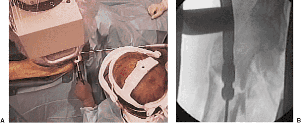
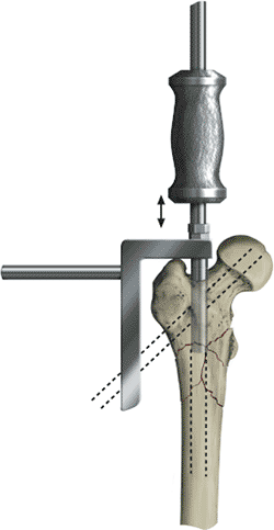
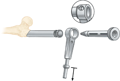
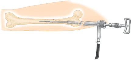
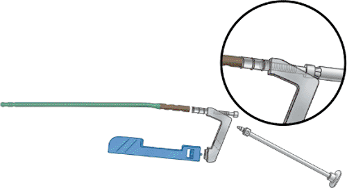
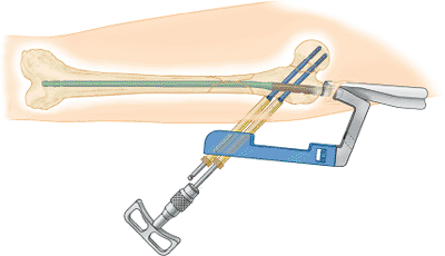
driving/proximal drill guide. When assembled properly, the nail will
have an anterior bow, and the orientation of the proximal drill guide
points laterally.
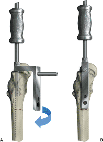
to the proximal drill guide, and the nail is inserted over the guide
wire. The proximal drill guide acts as a handle to control rotation and
aid in insertion of the nail (Fig. 20.13). The
surgeon must not strike the proximal drill guide directly, because this
may deform the targeting device and compromise proximal interlocking.
Once the nail has been inserted, the proximal targeting device should
be retightened. The nail is driven under radiographic control to within
1 to 2 cm of its anticipated depth.
person, so a reconstruction nail is inserted to the point where the
upper end of the nail will accommodate two proximal screws into the
femoral head. Frequently, minor adjustments in nail position, either
proximal or distal, are necessary to line up the holes in the nail
within the femoral head and neck. Nail insertion and screw placement
can be initially performed with the nail-length ruler and a radiopaque
ruler or guide. Its outline is drawn with a skin marker over the
femoral head and neck (Figs. 20.14 and 20.15).
With the nail nearly fully seated, the inferior drill sleeves are
placed into the proximal drill guide to extrapolate the eventual
location of the inferior screw.
the femoral head and neck. The proximal targeting guide is aligned with
the c-arm axis by rotating the proximal drill guide
in the transverse plane (Fig. 20.16).
If the proximal targeting device is radiopaque, the guide is
centralized with respect to the femoral head, bisecting the femoral
head in the coronal plane as seen on the true, lateral, c-arm view. The
posterior and anterior portion of the femoral head must be seen in
relation to the proximal drill guide for the surgeon to confirm that
the screws will be contained within the femoral head (Fig. 20.17).
Further verification of the proximal guide wires, drill bits, and
locking screws may be obtained with oblique c-arm views. With a skin
marker, a horizontal line is drawn on the lateral thigh as a reference
to correct rotation of the proximal drill guide (Fig. 20.18). The traction is released, and the nail is seated. The intramedullary guide wire is removed from the femur.
 |
|
Figure 20.13. Nail assembly with proximal drill guide.
|
 |
|
Figure 20.14. Overlay ruler is used to access anticipated final screw-insertion zone.
|
 |
|
Figure 20.15. Adjust nail-insertion depth for centering of proximal locking screws.
|
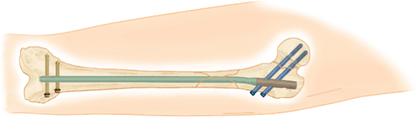
cancellous screws. For maximal stability, the proximal interlocking
screws should reach the dense subchondral bone of the femoral head. The
skin and fascia are incised through the inferior hole of the proximal
drill guide. The stacked drill sleeves are inserted through the
inferior hole and pushed to bone. The appropriate guide pin is inserted
through the drill sleeve and advanced into the femoral head at least 4
mm superior to the calcar and within 5 mm of the subchondral bone of
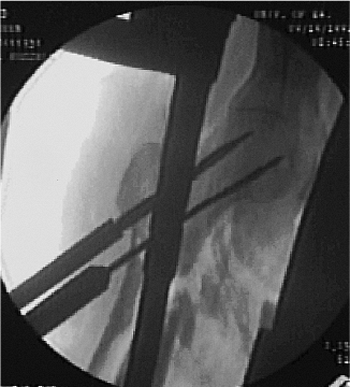
the femoral head. The position of the guide pin within the head is
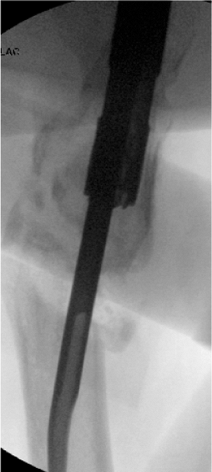
confirmed with AP and oblique lateral views with the c-arm (Fig. 20.19).
by the proximal drill guide but the femoral head is visible anteriorly
and posteriorly, then central placement of the pin can be inferred. For
further confirmation, the c-arm can be rotated anteriorly and
posteriorly from the true lateral position. The second guide pin is
placed in the superior hole of the nail, and its location within the
femoral head is confirmed with the c-arm. The skin and fascia are
incised through the superior hole of the proximal drill guide, and the
stacked drill sleeves are inserted
through
the superior hole. The drill sleeves are pushed to bone. The second
proximal guide pin is inserted through the drill sleeve and advanced
into the femoral head (Fig. 20.20).
 |
|
Figure 20.16. A,B.
Rotation of proximal drill guide to center guide for correct anteversion of screws into femoral head; drill guide should bisect the femoral head on the true lateral radiographic view. |
 |
|
Figure 20.17. Lateral fluoroscopic view with bisection of femoral head through use of drill guide for correct screw position.
|
removed if the screw is noncannulated. This leaves a pilot hole to
center the large step drill. The appropriate step drill is inserted
through the remaining drill sleeve into the femoral head to within 5 mm
of subchondral
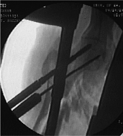
bone. The surgeon should verify that the drill sleeves are against bone (Fig. 20.21). Screw-length measurement is determined with calibrated drill bits (Fig. 20.22).
In another method, length can be assessed with the use of a depth
gauge. The appropriate lag screw is inserted through the drill sleeve
into the femoral head (Fig. 20.23). To maximize
purchase, the threads of the screws must lie totally within the femoral
head and not in the femoral neck. The remaining drill sleeves are
removed.
 |
|
Figure 20.18. The drill guide should be traced to serve as a visual reminder of correct anteversion.
|
 |
|
Figure 20.19. A,B.
Inferior guide wire is inserted, and correct placement to within 5-mm of subchondral bone and correct neck-shaft alignment are confirmed. |
similar to the insertion of the first screw: With the superior hole of
the drill guide, a guide pin, if not already in place, is advanced to
within 5 mm of subchondral bone. The guide pin and appropriate drill
sheaths for noncannulated screws are removed. The step drill is
inserted through the drill sleeve into the femoral head to within 5 mm
of the subchondral bone. The surgeon should verify that the drill
sleeve is against bone. The screw length is determined at this point
through use of the calibrated drills or by a depth gauge. The step
drill is removed. Tapping is usually recommended, but in dense bone in
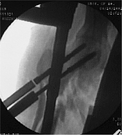
young patients, it is required (Fig. 20.24). The appropriately sized proximal screw is inserted into the femoral head. The
drill sleeve is removed, and with AP, lateral, and oblique views, the
surgeon confirms containment of both screws in the femoral head (Fig. 20.25).
For maximal stability, all threads of the proximal locking screws
should be within the femoral head. To avoid distraction, screw threads
must not be passed across any fracture line. Proximal interlocking is
now complete. Insertion of a distal locking screw improves stability
and fatigue life of the construct in comminuted fractures, and it
decreases the incidence of shortening and malrotation. I prefer a
freehand technique or use a radiolucent drill guide for distal
interlocking-screw placement (Fig. 20.26).
 |
|
Figure 20.20. Insert second guide wire for centering and stability of proximal guide.
|
 |
|
Figure 20.21. Use step drill for screw-tract preparation.
|
 |
|
Figure 20.22. Correct screw-length selection is determined from calibrated step drill.
|
 |
|
Figure 20.23. Proximal lag screw is inserted.
|
entire femur is scanned with the c-arm to confirm correct screw
placement, adequacy of reduction, stability at fracture site, and
proper nail length. The wounds are irrigated and closed in layers
(fascia, subcutaneous, and skin) in the standard fashion. Sterile
dressings are applied. If skeletal traction was used, the traction pin
is removed, and the wounds are covered with sterile dressings.
 |
|
Figure 20.24. Second guide wire is removed and step drill is used for drilling second screw; tapping is frequently required in dense bone.
|
 |
|
Figure 20.25. Second proximal screw is inserted, and seating is confirmed radiographically.
|
 |
|
Figure 20.26. A–C.
Freehand technique: hole is located with external marker and a stab incision is made over the hole axis; the trocar is inserted to dimple bone; drilling is done for bicortical fixation; screws are inserted. |
and bone loss. Pepper et al developed a third-generation nail insertion
technique that facilitates either piriformis or trochanteric
portal-entry selection. It also allows faster fracture reduction with
less chance of damage to the proximal femoral-bone stock when a closed
reaming system is used.
The affected limb is adducted 0 to 5 degrees because relatively less
adduction is required for a trochanteric portal. The affected hip is
flexed 15 to 40 degrees to facilitate the reduction of the distal
fragment to the proximal fragment. Traction is applied through a
skeletal pin or through the foot with the fracture-table foot holder.
The surgeon adjusts the affected limb for length and rotation by
comparing it with the unaffected limb. The surgeon further checks
rotation by rotating the c-arm to align the femoral neck in anteversion
and then making the appropriate correction by the foot, usually 0 to 15
degrees of external rotation.
 |
|
Figure 20.27. Supine position with both feet in traction. A,B. Note increased flexion and slight external rotation to better expose subtrochanteric fracture for trochanteric nail portal and (C) lateral decubitus positioning.
|
fracture table. It is used when the change of position of the femoral
head causes the leg to be internally rotated 10 to 15 degrees (see Fig. 20.27C).
The rotation is best checked by visualizing the femoral anteversion
proximally and matching it with correct rotation at the knee. The
greater trochanter is palpated. Fracture reduction is confirmed
possible before skin incision and after c-arm views of good quality are
obtained. A 2.5-cm incision is made 3 cm proximal to the greater
trochanter in line with the femoral shaft. The incision should be
carried through the fascia.
surgeon tightens the entry reamer connector onto the 14.0-mm channel
reamer and inserts the 12.5-mm entry reamer until it “clicks” into the
assembly. Then, power is applied to the 12.5-mm entry reamer to ream
the proximal section of the femur through the entry tool. The entry
tool–honeycomb assembly is oriented so that the superior side of the
bevel is medial. (This requires setting the entry tool indicator to “R”
for a left nail and to “L” for a right nail, which is opposite to the
standard femoral antegrade nail [FAN] technique and advanced until it
rests against the lateral aspect of the greater trochanter.) Suction is
attached to the entry tool to assist in blood evacuation and to
minimize blood aerosolization to which the operative team is subjected (Fig. 20.28).
The 3.2-mm tip-threaded guide wire is inserted through the honeycomb
and advanced 1 cm into the cortex at the tip of the greater trochanter,
as seen on the AP view, and in line with the center of the femoral
canal as visualized on the lateral view (Fig. 20.29A). With image guidance, a second guide wire may be used to refine the starting portal exactly.
 |
|
Figure 20.28. Entry portal tool assembly.
|
 |
|
Figure 20.29. Guide wire is inserted through entry portal tool. A. Guide wire insertion schematic. B. Position of guide wire. C. Radiographic control ape. D. Radiographic control lateral.
|
The channel reamer assembly is introduced over the tip-threaded guide
wire and advanced 1 to 2 cm into bone. The reamer assembly is then
manipulated under image guidance until the shaft axis and intended path
of the reamer form an angle of approximately 5 degrees in the AP view
and is in line in the ML view. The tip of the reamer should be directed
to a point just inferior to the normal location of the lesser
trochanter as seen on the AP view. Once the correct orientation is
obtained, the reamer assembly is advanced to full depth so that it
contacts the proximal end of the entry portal tool (Fig. 20.30).
This reamer assembly enlarges the proximal femur 1.0 mm over the
diameter of the nail head to 14.0 mm. The 12.5-mm entry reamer and
guide wire are removed, but the entry tool and 14.0-mm channel reamer
is kept in place.
reducer is placed through the entry tool and 14.0-mm channel reamer to
reduce the fracture. The reducer is advanced down the medullary canal
to the fracture site and then the proximal fragment is manipulated with
the
entry
portal tool and reducer until it is aligned with the distal-fragment
medullary canal. The tip of the reducer is rotated into the distal
medullary canal to capture the distal fragment (Figs. 20.31 and 20.32).
The 3.0-mm ball-tipped guide rod is inserted through the reducer into
the distal femur in the region of the old physeal scar. The reducer is
rotated to center the guide wire distally in the femur as seen on AP
and lateral views.
 |
|
Figure 20.30. Channel reamer insertion schematic. A. Insertion of channel reamer. B. Radiograph AP. C. Radiograph lateral.
|
patient requirements and injury. If reaming is planned, progressive
reamers should be used through the entry tool. Unreamed nails are
selected based on preoperative planning but should be of sufficient
size to provide translational fill of the intramedullary canal in the
mid diaphysis. Once the guide rod is in place, the reducer is removed,
but the surgeon should leave the 14.0-mm channel reamer in place. The
channel reamer protects the proximal portal from eccentric reaming,
which could lead to a varus reduction (Figs. 20.33 and 20.34).
The femoral shaft should be sequentially reamed, through the 14.0-mm
channel reamer, to 1.0 mm or more above the chosen nail diameter. For
more curved femoral shafts, 1.5 to 2.0 mm of reaming greater than the
nail diameter may be required to avoid nail incarceration. In patients
who have long femurs, the flex reamer extender may be added to extend
the shaft of the flexible reamer for very distal fractures or nails
longer than 42 cm.
removed before the diaphysis is reamed with the 13.5- and 14.0-mm
reamer diameters. Usually a 13-mm nail will be reamed at the diaphysis
to 14 mm. However, the reamer should be inserted into the femur before
reaming is started, and to avoid portal damage, the surgeon should stop
reaming before final extraction of the reamer from the medullary canal.
 |
|
Figure 20.31. Reducer schematic.
|
 |
|
Figure 20.32. Reducer insertion across fracture site.
|
 |
|
Figure 20.33. Reamer canal preparation through channel reamer to protect the trochanteric region from eccentric reaming.
|
 |
|
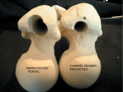
Figure 20.34. Effect of eccentric reaming on portal with second-generation nail instrumentation with unprotected reaming (left) versus minimally invasive channel reamer technique (right).
|
templating. A nail that has a larger diameter than the last reamer used
should never be inserted. With the distal tip of the guide rod at the
desired level of the distal femur, the nail length is measured by
positioning the open end of the ruler over the exposed end of the guide
rod and pushing the end down to the level of bone through the 14-mm
channel reamer. The position of the ruler should be confirmed on the
image intensifier. The tip of the ruler should line up with the final
position of the proximal end of the nail. This may be predetermined by
preoperative templating.
of the greater trochanter allows optimal screw positioning. However,
successful positioning also depends on the femoral neck-shaft angle and
the screw-nail angle, usually a 130 or 135 degree nail. The nail length
is read from the calibrations exposed at the other end of the ruler.
The guide rod is left in place for placement of the nail. Exchange of
the ball-tipped guide rod is not necessary.
the guide bolt wrench is used to secure the bolt to the nail. The
impactor is screwed onto the top of the drill guide to drive the nail
into the medullary canal (Fig. 20.35A). The
skin protector is inserted into the incision parallel to the entry
reamer tool. The entry reamer tool and 14-mm channel reamer are
removed. The skin protector will assist in maintaining control of the
surrounding tissues and provide continued access to the bone. The nail
is advanced over the guide rod with the nail rotated 90 degrees with
the proximal guide aimed anteriorly, and the nail is inserted carefully
past the fracture; the nail is rotated into correct rotational
alignment after it is approximately 50% inserted (see Fig. 20.35B,C).
This insertion technique minimizes insertion forces required for nail
insertion from the trochanteric portal. The guide rod is removed after
the nail is inserted to within 2 cm of the final position of the nail
tip and before the locking screws are inserted.
cephalomedullary technique, only one additional instrument is attached
to convert the nail into a cephalomedullary construct. This drop is
either a 135 or 130 degree guide and may be added after the nail is
inserted, or if a
reconstruction
nail is planned, before nail insertion. Screws (6.4 mm) (blue) screws
are used to lock the 10-mm, 11.5-mm, and 13-mm diameter trochanteric
antegrade nails (TAN) implants proximally in the recon mode. The guide
bolt is inserted into the drill guide and the guide bolt wrench is used
to secure the bolt to the nail. The hip guide is connected to the drill
guide. The guide is keyed so that it will only fit one way. The knurled
knob is tightened by hand until snug. The end of the guide bolt wrench
is used to finish tightening the guide in place (Fig. 20.36).
 |
|
Figure 20.35. Nail insertion. A. Assembly of nail for insertion. B,C. Nail is inserted and internally rotated 90 degrees until 50% of nail is inserted. It is then rotated into final position.
|
checked by the surgeon passing the medium screwdriver through the gold,
outer, drill sleeve up into the holes of the nail. The impactor should
be screwed onto the top of the drill guide to drive the nail into the
medullary canal. The skin protector is inserted in the incision
parallel to the entry reamer tool. The entry reamer tool and channel
reamer are removed. The skin protector will assist
in
maintaining control of the surrounding tissues and provide continued
access to the bone. The nail is advanced over the guide rod and
carefully past the fracture. The guide rod is removed after the nail is
inserted and before the locking screws are inserted.
 |
|
Figure 20.36. Proximal locking recon mode. Recon drop assembly.
|
must be noted before drilling into the femoral head: anteversion
alignment and depth of nail insertion. To begin, the surgeon rotates
the c-arm proximally until a true lateral of the hip is visualized;
this gives the correct axis of alignment for anteversion. The handle of
the nail guide is rotated until it bisects the femoral head in the
lateral view. In this position, the nail and guide are overlaid on the
center of the femoral head such that femoral head is visualized
anteriorly and posteriorly. This position is marked with a skin marker
on the leg parallel to the driving handle. Next, the c-arm is rotated
into an AP view through the use of the calibrated notches on the
proximal attachment of the nail, which is visualized radiographically.
determining the depth of nail insertion will center both screws within
the femoral head. Usually, the nail will be countersunk 5 to 15 mm
below the tip of the greater trochanter. As a rule, the inferior drill
is placed first, then the most proximal drill is placed (Fig. 20.37).
These screws are angled at 130 or 135 degree in relation to the shaft.
If both screws will not seat within the femoral head, too much varus
positioning of the proximal fragment has probably occurred, or the
proximal nail entry portal is too lateral. With the trochanteric
portal, if the varus deformity originates medial to the nail insertion,
traction and adduction may correct the varus. An incision is made at
the entry holes of the proximal screw sleeves, and the two puncture
wounds are connected; a 2.5-cm incision will accommodate the insertion
of both screws. The silver, inner, drill sleeve is inserted into the
gold, outer, drill sleeve and they are pushed to bone. The 4.0-mm drill
bit is inserted into the silver, inner, drill sleeve and power is
conducted through the miniconnector.
desired depth and position. The femoral neck is drilled with the 6.4-mm
step drill to slightly less than the depth desired. The alignment is
checked in the AP view and 15-degree lateral views again before the
6.4-mm drill is removed. The 6.4-mm tap should be used in very dense
bone. The depth for the screw length is measured from the calibrations
on the drill or tap with respect to the gold, outer, drill sleeve. The
appropriate-length 6.4-mm screw is attached to the medium screwdriver.
The screwdriver T handle is attached and the captured screw is inserted
into the inferior proximal hole. Once the first screw is inserted, the
screwdriver should not be disassembled.
from the screws, proximal locking is complete. Distal locking is
performed with standard freehand technique. Two distal locking screws
are preferred for very comminuted fractures and long spiral-fracture
components into the diaphysis. The freehand technique is used with the
c-arm placed medial to the patient, allowing for proper image of the
femur (Fig. 20.39). Five mm (gold) screws are used to distal lock 10-mm, 11.5-mm, and 13-mm diameter TAN Implants.
 |
|
Figure 20.37. Proximal screw preparation. A. Proximal drilling through blue recon drop. B. Second drill insertion.
|
 |
|
Figure 20.38. Final tightening of both compression lag screws with traction off.
|
is removed with the guide bolt wrench; the wounds are irrigated and
closed in a standard fashion. Rotation and final check of length are
performed before the patient is transferred off the operative field.
mobilized from the bed to chair and gait trained with a walker or
crutches on the first or second postoperative day. Thromboembolic
prophylaxis is usually begun 12 hours after surgery with a
low-molecular-weight heparin and continued for 7 to 14 days, depending
on the patient’s mobility. Weight bearing is restricted to 10 to 15 kg
on the affected extremity in comminuted fractures. If cortical contact
is restored and bone quality is good, weight bearing is permitted as
tolerated with crutches or walker. Range-of-motion exercises and
straight-leg lifts are started in the first week. Patients are usually
discharged to home on the third or fourth postoperative day, when they
demonstrate lower-extremity control sufficient for household ambulation
with crutches or a walker.
radiographs are obtained at each visit. When callus is detected
(usually at 4 to 8 weeks), progressive weight bearing is allowed.
Patients
must demonstrate full weight bearing on the affected leg for 60 seconds
before crutches are discontinued and have equal abductor strength with
standing lateral leg lifts without a Trendelenberg sign. Frequently,
the patients have rehabilitated the fractured side but have neglected
the opposite side, resulting in a Trendelenberg gait without ambulatory
support. A progressive, resistance, exercise program is prescribed, and
swimming or stationary bicycling is recommended.
 |
|
Figure 20.39. Distal interlocking with freehand technique for static construct.
|
radiographs shows mature radiographic callus bridging of the fracture
site: rarely before 1 year. A general anesthetic is required and
usually a 24-hour hospitalization. Patients use crutches after implant
removal until their gait returns to the pre-implant–removal status.
After implant removal, contact sports are avoided for 3 months.
community-ambulation status within 6 to 8 weeks with crutches, begin
driving motor vehicles at 8 to 16 weeks, and are full weight bearing by
4 to 6 months after injury. Patients can expect functional recovery
sufficient to return to their previous occupations in most cases. Union
rates after closed reconstruction nailing are 95% to 100% in acute
subtrochanteric fractures uncomplicated by other injuries.
treatments for subtrochanteric femur fractures. As with most hip
fractures, avoidance of varus and significant leg-length discrepancies
are tantamount to a good result for the patient. Most patients return
to their previous occupations and recreational activities if functional
restoration is achieved. Most persisting problems are related to
associated knee or neurological injuries. Sanders et al proposed a
rating system for subtrochanteric fractures, but no comparative series
are yet available with this outcome measure.
significantly more difficult than for standard femoral nailing. When a
piriformis portal nail is used, eccentric, lateral, portal placement or
portal damage can result in comminution of the medial cortex and varus
displacement of the hip with nail insertion (Fig. 20.40). After subtrochanteric fractures, strong
muscle pull leads to flexion, external rotation, and varus positioning
of the proximal fragment. This increases the difficulty in c-arm
visualization of the entry portal. The problem may be solved by
internally rotating the leg and attempting a closed reduction of the
hip or by inserting a pin percutaneously into the trochanteric mass and
using this as a joystick to rotate the proximal femur into a more
anatomically recognizable position (Fig. 20.41).
 |
|
Figure 20.40. Varus deformity with nonunion and medial comminution from eccentric lateral portal with piriformis design nail.
|
 |
|
Figure 20.41. Use of Schanz pin inserted percutaneously to facilitate reduction of the proximal fragment.
|
in obese patients, a straight nail driver will tend to offset the nail
laterally and force the hip into varus. This occurs because of driver
pressure on the lateral ilium. To restore normal hip alignment, one may
use an offset driver and apply pressure medially through the driver the
nail is inserted to the correct depth. In an alternative method,
nailing in the lateral decubitus position may decrease the tendency
toward varus mal-alignment.
fractures with first- and second-generation antegrade-nailing
techniques in a level-one trauma center with trauma, orthopedic, staff
surgeons. Russell and Taylor studied the problem of malunions and loss
of reduction with intramedullary nailing of subtrochanteric fractures.
The technical complications relate to nail selection and surgical
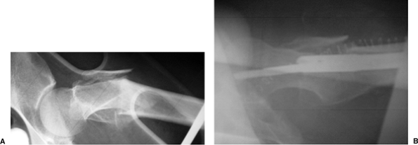
technique. First, with Russell-Taylor 1B, 2A, and 2B fracture patterns,
a cephalomedullary interlocking nail must be used instead of a
centromedullary interlocking construct. If fracture lines extend into
the medial calcar region or trochanteric area, a single, diagonal,
locking screw will not have sufficient stability (Fig. 20.42).
The problems encountered result from combinations of four errors:
incorrect starting point, loss of trajectory control of the reamers in
the proximal femur, failure to obtain reduction of the fracture prior
to nail insertion, and entry portal damage during fracture reduction
and medullary canal preparation.
piriformis portal is very difficult to obtain with patient supine
positioning, and the deformity of the subtrochanteric fracture makes
the piriformis region very difficult to identify with the image
intensifier. Frequently, the surgeon compromises the portal by starting
too posterior or too anterior and too far lateral for a conventional
piriformis-design nail. In an attempt to reach the medial side of the
trochanter, the entry portal is damaged.
fracture reduction; rather it is the trajectory of the cutting tools
that facilitates the reduction of the proximal fragment. If the
trajectory is anterior to posterior in the proximal femur, it will
induce a varus reduction of the hip upon nail insertion (Fig. 20.43).
The MINIT allows precise machining of the proximal fragment to optimize
reduction with nail insertion. The channel reamer then protects the
portal during fracture reduction and diaphyseal reaming. This precise
trajectory
control coupled with the protection of the portal with the channel
reamer optimizes the fracture reduction made via nail insertion (Fig. 20.44).
The development of nails with smaller proximal geometries that make
them better suited for a trochanteric portal than the original
Russell-Taylor nail, allows nail insertion in between the gluteus
minimus and short external rotators such that the MINIT spares the
important tendon insertion. In addition, use of these optimized nails
means that the trochanteric portal can be
obtained without the excessive varus positioning required with the piriformis technique (Fig. 20.45).
 |
|
Figure 20.42.
Russell-Taylor 1B fracture pattern with failed standard-screw construct in proximal femur. A reconstruction nail construct is recommended for Russell-Taylor IB fractures. |
 |
|
Figure 20.43.
Model of varus and flexion deformity of the proximal femur with trajectory of proximal fragment directed posteriorly and lateral placement of the entry portal. |
 |
|
Figure 20.44. A. Lateral radiograph of subtrochanteric fracture with flexion deformity of proximal femur. B.
Correction of deformity with channel reamer technique creating an anterior trajectory along anterior cortical wall; note resultant correction of deformity with nail placement. |
 |
|
Figure 20.45.
New trochanteric portal with MINIT. Placement is just medial to the gluteus medius tendon on the left and anterior to the piriformis tendon insertion inferiorly. |
observed a significantly decreased malunion rate with the use of MINIT
via the channel reamer. In 56 consecutive cases of subtrochanteric
fractures, use of the MINIT with the channel reamer resulted in a 95%
rate of reduction with less than 5 degrees of deformity in any plane
and a 81% rate of normal alignment when MINIT was not used.
screw centralization of the femoral head can be surprisingly difficult.
Preoperative templates can be helpful in determining the diameter of
the femoral neck and aid in selection of the proper implant.
particularly in the lateral projection, may be difficult. Rotation of
the c-arm until a true lateral of the femoral head and neck is the key
to successful proximal-screw placement. This is facilitated by
temporarily rotating the proximal guide anteriorly. Once a true lateral
of the femoral neck can be visualized and a reduction confirmed, the
handle is rotated posteriorly until the opaque guide bisects the
femoral head. This will allow visualization of the femoral head
anterior and posterior to the locking guide. When a portion of the
femoral head anterior and posterior to the proximal guide handle is
visualized, the screws will be contained in the centered position of
the femoral head (see Fig. 20.17). I favor screws slightly anterior in the femoral head.
head is anterior to the shaft of the femur, which requires the proximal
drill guide to be rotated slightly below horizontal to prevent
posterior screw placement in the femoral head. Anteversion built into
the nail compensates for the anterior femoral-head offset from the
center of the medullary canal. This minimizes the amount of external
rotation needed to insert the nail and optimizes distal interlocking so
that distal screw insertion is not too posterior at the knee. During
insertion, the proximal locking screws tend to be placed in
retroversion. Even though 8 to 15 degrees of anteversion (in relation
to the distal locking holes) is built into most reconstruction nails,
the proximal drill guide should be positioned slightly below the
horizontal axis of the limb. Rotational alignment and centralization of
the proximal drill guide is confirmed on the lateral c-arm view.
femoral head may be difficult. The most common causes for this problem
are varus reduction of the proximal fragment, a narrow femoral neck,
and preexisting coxa vara in reference to the neck-shaft angle of the
proximal screws and nail. If the proximal screws transverse an inferior
to superior tract in the femoral head or the surgeon perceives that
only one screw can be inserted, the fracture is probably in varus.
the nail. This can be minimized by preoperative planning and
referencing the tip of the greater trochanter to the center of the
femoral head. The goal is to try to place the inferior screw just above
the medial femoral cortex. If the nail is inserted too deep, it will be
difficult to insert the screw or the screw will penetrate the cortex.
The guide wire should be placed 4 to 5 mm above the medial femoral
neck. In an alternative, a Kirschner (K) wire may be inserted
percutaneously anterior to the femoral neck into the desired position
and the proximal driving guide inserted by using this reference point.
will note that the proximal locking screw will not advance past the
nail into the femoral neck. This is usually because of the partially
threaded proximal screw functioning as a bolt. When all of the threads
of the bolt become contained within the proximal nail, no threads are
available to pull the nail into the bone. At this point, the surgeon
may tap the screw into the femoral head until threads contact bone and
start the threading process again.
operating room. In cases of severe osteoporosis or pathologic lesions
in which the screws do not have good fixation, augmentation of proximal
screw fixation with nonpressurized methyl methacrylate is advisable.
techniques and probably occurs at a rate of 1% in closed fractures and
slightly higher in open fractures. If the implant is stable, incision
and drainage of the acute infection and intravenous antibiotics are
recommended. Once the fracture has united, the implant should be
removed and the canal debrided. A more difficult problem is loss of
fixation accompanied with an occult infection. Depending on the type of
organism, debridement and exchange nailing and antibiotics may be
successful. If a virulent organism is encountered with loss of nail
stability, traction or external fixation or both may be required; a
higher morbidity expected in this latter situation.
fixation or nail or screw breakage. Nail breakage usually implies
nonunion and fatigue failure. If the problem is aseptic, exchange
reamed nailing is recommended. Loss of proximal screw fixation acutely
reflects pathologic bone (i.e., osteopenia or neoplasia) or poor
initial-screw placement. Late loss of screw fixation implicates
nonunion. Revision nailing and bone grafting are required for
successful salvage. Distal screw breakage early is usually the result
of premature or excessive weight bearing. Length or rotational loss may
occur if distal screws are removed prematurely or if the patient
engages in excessive weight bearing.
not be complicated with implant failure. If the existing implant is
loose, it should be revised to the most suitable fixation, usually to a
larger, reamed, interlocking, reconstruction nail. In hypertrophic
nonunions, exchange nailing is frequently all that will be required.
When the outcome of these solutions is in doubt or in atrophic
nonunions, autologous cancellous iliac-bone graft to the nonunion site
with a Phemister–Judet technique is advised.
about the hip or knee. Heterotopic ossification is a frequent
radiographic finding but rarely symptomatic. Associated patella and
peri-articular knee fractures, as well as soft-tissue injuries, can
result in the loss of motion after subtrochanteric fractures.
Neurological injuries associated with the subtrochanteric fracture are
rare but must be evaluated carefully before nailing is done. Sciatic
and pudendal nerve injuries observed postoperatively are usually caused
by excessive traction required for reduction or compartment syndrome.
These injuries do not always resolve with time and therefore may result
in significant morbidity.
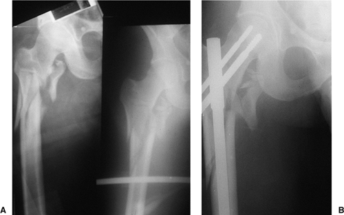
malfunction while jumping. On impact, he had a closed, displaced,
proximal, femur fracture (Fig. 20.46). The
patient underwent reamed, static, reconstruction nailing. His fracture
united at 3 months, and he returned to his work without restrictions.
This fracture pattern probably represents the ideal indication for a
reconstruction nail; that is, it was a subtrochanteric fracture with
loss of medial cortical stability and with fracture of the lesser
trochanter (Russell–Taylor IB). The fracture did not extend into the
piriformis fossa.
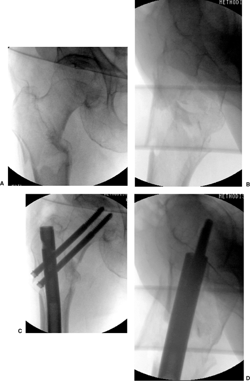
fall down stairs, sustained a Russell-Taylor IIB, closed,
subtrochanteric fracture (Fig. 20.47). She
underwent closed TriGen reconstruction nailing with a trochanteric
portal nail. Her fracture united, and she regained independent
ambulatory status by 4 months after surgery. This case represents the
advantages of a trochanteric portal with the MINIT in comminuted
fracture situations.
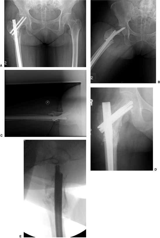
nondisplaced femoral-neck fracture that was treated with multiple
screws. Two months after the surgery, she fell again, sustaining a
subtrochanteric fracture. Her injury was revised with a piriformis
entry nail but in a malreduced position. After 1 year, her fracture was
successfully revised with a percutaneous osteotomy, autogenous bone
grafting with DBM extender, and TriGen Intertan (Smith & Nephew,
Memphis, TN) nailing in a reduced position with the channel reamer
technique (Fig. 20.48).
 |
|
Figure 20.46. A,B. Subtrochanteric fracture caused from parachuting accident. Stabilization with Russell-Taylor reconstruction nail, static mode.
|
 |
|
Figure 20.47. A,B Russell Taylor IIB subtrochanteric fracture from a low-level fall. C,D. Reduction and stabilization with trochanteric antegrade TriGen nail in reconstruction mode with MINIT.
|
 |
|
Figure 20.48. A–C.
Preoperative nonunion of subtrochanteric fracture with malreduction of proximal fragment. Note poor bone apposition because of the malreduction. D,E. Postoperative appearance with percutaneous osteotomy and grafting with reduction of deformity and fixation through use of TriGen Intertan system. |
GJ, Ward AJ. Reconstruction femoral nailing for nonunion of
subtrochanteric fracture: a revision technique following dynamic
condylar screw failure. Int Orthop 1996;20:55–57.
J, Russell T, Sanders R, et al. Minimally invasive intramedullary nail
insertion instruments and method. US Patent 5,951,561. September 14,
1999.
JC, Russell TA, Walker BC. Intramedullary nailing of complex
subtrochanteric fracture of the femur. Paper presented at: American
Academy of Orthopedic Surgeons Orthopaedic Transactions; 1992.
DC, Erpelding JM, Whitman CS, et al. Treatment of comminuted
subtrochanteric femoral fractures in a young population with a
reconstruction nail. Mil Med 1996;161:735–738.