
VIII – THE SPINE > Trauma > CHAPTER 139 – UPPER CERVICAL SPINE
FRACTURES AND INSTABILITY
Alvin and Lois Lapidus Cancer Institute, Professor of Orthopaedic
Surgery and Oncology, Sinai Hospital of Baltimore, Baltimore, Maryland,
21215.
of injuries whose patterns differ from those of injuries in the lower
cervical, thoracic, and lumbar spine because of the unique anatomic
configuration of the vertebral elements of the craniocervicum (45,57).
The craniocervicum includes the base of the skull, the atlas, and axis,
and is unique both in its bony as well as ligamentous structure. A
variety of conditions can lead to upper cervical spine instability
(infections, tumors, spondylosis, and congenital abnormalities), but
the most common cause is direct trauma. Although upper cervical
fractures occur as a result of mechanisms of injury that are similar to
those causing other spine fractures (i.e., motor vehicle accidents,
falls, diving, or direct trauma), they are nevertheless unique for
several reasons. First, in autopsy series (2,13,17),
many injuries to the upper cervical spine resulted in trauma to the
brain stem and thus immediate death. In addition, in those patients
surviving their initial trauma, the incidence of neurologic injury as a
direct result of fractures and dislocations in the craniocervicum is
proportionately less than the incidence in other areas of the cervical
spine because of the relatively large area available for the spinal
cord within the spinal canal. Again, because of the unique relationship
of this spinal region to the skull, most fractures in the upper
cervical spine result from a force applied through the skull, with
resultant excessive motion of the head and upper cervical spine,
creating the injury pattern. Although the fractures in the upper
cervical spine may be survivable, some of these patients succumb as a
result of associated severe head injury. In fact, many of the
neurologic deficit patterns are a result not of the injuries to the
spine but of direct head injuries. To understand the nature of these
injuries and to be able to apply the most appropriate treatment
methodologies, the physician must first thoroughly appreciate the
anatomic considerations of the
craniocervicum
and then fully understand the mechanism associated with each injury
pattern. Appreciation of the significance of the injury in relation to
the immediate and subsequent potential instability is important in
preventing both undertreatment and overtreatment of injuries in this
location. It also may alert the physician to potential pitfalls in
treatment modalities that may apply to the various injury types.
area at the base of the skull, the atlas, and the axis. The area is
unique because it is the junction between the skull and the cervical
spine, and is characterized by extreme mobility (37).
It is unique also because of the size, shape, and location of the
joints that allow motion between the occiput and the atlas or the atlas
and the axis. At the lower end of the craniocervicum (C2–C3), there is
a transition in the size, shape, and location of the joints,
transitioning to the more usual pattern seen in the lower cervical
spine. Forces applied to the craniocervicum may result in injuries
having far different patterns and resultant instabilities than those
seen in the lower cervical spine.
with reference to the spinal canal in that area. Those joints are made
up of convex-shaped lateral masses adjacent to the foramen magnum that
articulate with the concave lateral masses of the atlas. The joints are
trapezoidally shaped and are somewhat wider medially than laterally. In
children, these joints are less concave and flatter, and therefore,
they restrict motion to a less significant degree than they do in
adults. Therefore, children have more mobility and are more predisposed
to injury at this level (5). The normal range
of motion at the occipitocervical junction is 21° of extension (which
is in part limited by the occiput abutting on the posterior arc of the
atlas) (89), 3° of flexion, 7° of rotation, and 5° of lateral bending (64).
element present in the remainder of the vertebrae of the cervical
spine. Embryologically, the vertebral body of C-1 is absorbed into the
formation of the dens process of C-2; therefore, the atlas has two
lateral masses connected by an anterior and a posterior arch. The
anterior arch is thicker and shorter than the posterior arch. The
posterior arch has a tubercle in its posterior midportion and two
relatively flatter areas just posterior to the lateral masses, over
which the vertebral artery runs after it exits from the foramen in C-2.
The shape of the lateral masses is important because it helps one
understand how injuries to C-1 occur. The articular surfaces for C1–C2
and also occiput–C1 are concave, with that of the atlantoaxial joint
being somewhat flatter than that of the occipitocervical joint. The
resultant shape of the C-1 lateral mass is that it is thinner medially
than laterally; thus, when axial loading forces are applied across the
craniocervicum, there is a resultant force that serves to displace the
lateral masses of C-1 in a lateral direction.
because the atlantoaxial joint has two different sets of articulations.
The first is the articulation of the slightly convex inferior articular
process of the atlas with a slightly convex superior articular process
of the atlas. Both joints are oriented in the horizontal plane with a
medial inclination of approximately 35°. These joints permit rotation,
accounting for nearly 50% of the rotation in the cervical spine (69).
The odontoid process projects up inside the ring of the axis, forming a
second joint with the anterior arch of the atlas. The dens generally is
between 14 and 15 mm in height and thus is approximately 40% of the
overall height of the axis (74). The overall diameter of the atlas is quite large in relation to the space necessary for the spinal cord (82).
Generally, the midsagittal diameter of the cord is one third of the
midsagittal diameter of the inner surface of the axis. Actual rotation
between the occiput and C-1 is generally approximately 5° to 7°, with
more than 8° being pathologic, and at the atlantoaxial joint, the
amount of normal rotation is approximately 43°, with more than 50°
representing hypermobility and approximately 65° of rotation required
for atlantoaxial dislocation (20,38).
At C-2, the isolation of the pedicles of the axis between the
atlantoaxial joint anterior to them and the C2–C3 joint posterior to
them contributes to the occurrence of fractures at the base of the
pedicles. The relative stability of the craniocervicum as a unit
isolates the pedicles of C-2, predisposing them to fractures. Finally,
the large bifid process of C-2 is an anatomic landmark for physical
examination as well as for anatomic dissection.
development of the upper cervical spine is also helpful in further
understanding injuries to this area. Although all other cervical
vertebrae develop from at least three ossific nuclei, the atlas
develops from only two centers of ossification, which usually fuse
together between 3 and 5 years of age. Because there is an ossific
center in each lateral mass, defects in both the anterior arch and
posterior arch can occur. The axis has four centers of ossification,
which also tend to fuse together between 3 and 6 years of age, with the
exception of the junction between the odontoid process and the body,
which may persist up to 11 years of age. The presence of persistent
congenital defects in the ring of C-1 or C-2 in the adult and delayed
fusion of ossific nuclei in children should not be confused with acute
fractures.
both the anterior and posterior ascending arteries from the vertebral
arteries that anastomose to create a rich vascular network. The
cartilage plate that separates the odontoid
from
the body of C-2, as previously mentioned, tends to ossify around 7
years of age, preventing direct vascularization from the rich plexus in
the vascular body. There is also a zone of ossification at the tip of
the dens, which appears between 3 and 6 years of age and can remain
open until 12 years of age. Both of these delayed closures can be
mistaken as fractures.
of the craniocervicum is far different from that between the bony
components of the lower cervical spine. The major difference is that
there is no disc between occiput and C-1 or between C-1 and C-2 because
there is no vertebral body at C-1. Therefore, without the stability
provided by the intervertebral discs, the ligamentous integrity of the
craniocervicum is provided by a structure quite different from that in
the lower cervical spine. The central point of ligamentous stability in
the upper cervical spine is the odontoid process. Affixed to it are
several ligaments, which provide resistance to translation, flexion,
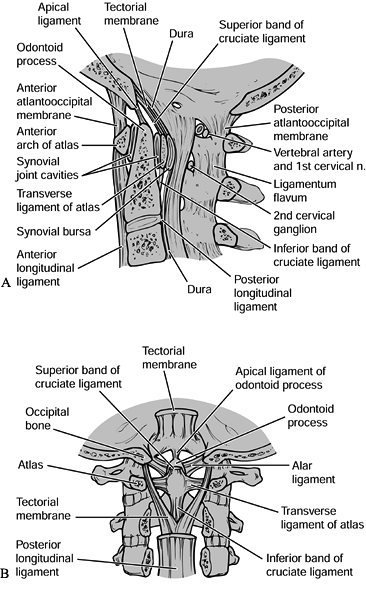
extension, and rotation. The transverse ligament
is fixed at the tubercle on the lateral mass at one side of the atlas
and traverses just posterior to the odontoid process to attach to the
tubercle of the contralateral lateral mass. It secures the anterior
surface of the dens in close proximity to the posterior facet of the
anterior arch of the atlas. The transverse ligament provides stability
in flexion between the atlas and the axis, and also prevents anterior
translation of the atlas on the axis (29). The alar ligaments attach to the tip of the dens (Fig. 139.1).
They actually arise from the medial aspect of the occipital condyles
and insert along the tip of the odontoid. They function to prevent
anterior translation at C1–C2 as well as to restrict rotation and
lateral bending at that level (22,23). The apical ligament
arises from the rim of the foramen magnum and inserts more centrally
than the alar ligaments into the tip of the dens. Finally, the accessory ligaments
arise from the lateral masses of C-2 and insert into the base of the
dens. These three types of ligaments—the alar, apical, and accessory
ligaments—act as important secondary restraints to C1–C2 translation,
especially in the event of failure of the transverse ligament (29).
 |
|
Figure 139.1. A:
A midsagittal section through the craniocervical junction. This figure shows the appropriate relationship of the basion or anterior aspect of the foramen magnum to the ring of C-1 and the odontoid process, and nicely illustrates the ligaments at the occipitocervical junction. B: A coronal section demonstrating the ligaments at the craniocervical junction. Note especially the alar ligaments and the tectorial membrane. (Redrawn from Martel W. The Occipito-atlantoaxial Joints in Rheumatoid Arthritis and Ankylosing Spondylitis. AJR 1961;86:223, with permission.) |
two different mechanisms of injury. First, a severe flexion force
between C-1 and C-2 may result in failure of the transverse ligament by
impingement on the dens process, and this may also result in failure of
the alar, apical, and accessory ligaments. In contrast, the transverse
ligament can fail in tension with axial loading applied across C1–C2,
resulting in failure of the accessory ligaments and transverse
ligaments, but because of the direction of attachment, the alar and
apical ligaments remain intact. Additional stability to this complex is
imparted by the joint capsules, especially the C1–C2 capsules (16).
These capsules function to limit rotation and, to a lesser degree,
translation at the C1–C2 level. Posterior to the central ligamentous
complex is the pectoral ligament. This is an attenuation of the
interspinous ligament, which is a direct restraint to flexion. The
final ligamentous component in the upper cervical spine is the
continuation of the anterior longitudinal ligament. This, again, is
somewhat attenuated, although it provides restraint to extension in the
upper cervical spine.
There are three elements in the vascular anatomy of concern: the
position and course of the vertebral arteries; the plexus of
thin-walled vessels lying just posterior to the facet capsule at C1–C2;
and the vascular supply surrounding the dens process. The vertebral
arteries course upward through the foramen in C-2, then loop over the
posterior arch of the atlas approximately 1.5 to 2 cm lateral to the
tubercle of the posterior arch. The vertebral artery is vulnerable to
injury during surgery in two separate areas. Dissection of the ring of
C-1 more than 2 cm lateral from the midline may expose the vertebral
artery to trauma. Also, the insertion of atlantoaxial screws exposes
the vertebral artery to injury by direct trauma from a drill bit as it
traverses the C-2 body. Because the location of the vertebral artery
within C-2 varies, determine its position radiographically before screw
fixation (65). It is, however, also important
to know that because the vertebral arteries are paired structures (with
one usually larger and, therefore, dominant over the other in terms of
blood supply), injury to a single vertebral artery rarely results in
significant neurologic deficit. In addition, as shown by Rauschning,
there is a plexus of thin-walled vessels lying superficial to the facet
capsule of C1–C2 with exposure of the C1–C2 articulation from a
posterior direction. Sharp dissection through the soft tissue
superficial to these vessels may result in profuse bleeding; there is
less probability of injuring this vascular network by blunt dissection
of the soft tissues caudal to rostral along the pedicle of C-2.
Although the bleeding may be bothersome during the course of surgery,
the consequences of disruption of the venous plexus is not significant.
the sole reason for the high rate of nonunion of the dens, it has since
been found that in fact there is a significant endosteal and
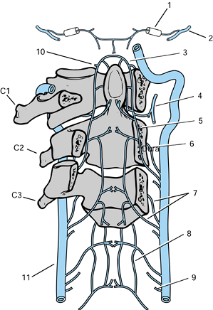
ligamentous blood supply (Fig. 139.2). The
combination of the carotid arteries and vertebral arteries supply
sufficient blood vessels to the dens process. Even the internal carotid
supplies vessels to the dens through arteries that anastomose in a
vascular arcade, and the dens may even have a direct blood supply
through an ascending pharyngeal artery.
 |
|
Figure 139.2.
The arterial supply to the upper cervical vertebrae and the odontoid process. 1, Hypoglossal canal containing the meningeal artery. 2, Occipital artery. 3, Apical arcade of the odontoid process. 4, Ascending pharyngeal artery giving a collateral branch beneath the anterior arch of the atlas. 5, Posterior ascending artery. 6, Anterior ascending artery. 7, Precentral and postcentral arteries to a typical cervical vertebral body. 8, Anterior spinal plexus. 9, Medullary branch of the vertebral artery. Radicular, prelaminar, and meningeal branches are also found at each level. 10, Collateral to the ascending pharyngeal artery passing rostral to the anterior arch of the atlas. 11, Left vertebral artery. (Redrawn from Parke WW. The Vascular Relations of the Upper Cervical Vertebrae. Orthop Clin North Am 1978;9:879, with permission.) |
trauma to the cervical spine be first assessed for adequacy of airway,
breathing, and circulation according to the American Trauma Life
Support (ATLS) protocols, it is even more vital in patients with
injuries to the upper cervical spine. Especially with injuries caused
by distraction at the level of occiput–C1 or C1–C2, brain stem
contusion is possible, resulting in cessation of spontaneous
respiration. Emergent maintenance of airway and respiration may be the
key to patient survival. Treat any patient with a head injury who is
comatose or obtunded as if an injury is present until it is clearly
ruled out. As with other spinal injuries, immobilize the entire spine
on a backboard with a rigid collar. The physical examination of
patients with upper cervical spine injuries begins with an evaluation
of the skull for evidence of head trauma, including scalp or facial
lacerations. Localizing signs, such as tenderness and especially the
location of trauma to the skull, is helpful in
the
further evaluation of the patient as well as ultimately determining the
mechanism of injury. In the awake, alert patient, palpate the entire
spine for areas of localized tenderness or asymmetry.
function and strength; evaluate sensation with pinprick and
light-touch; check the deep tendon reflexes, cranial nerves, and rectal
tone and perianal sensation. Physical findings help in ordering proper
radiographic evaluation of the patient.
neurologic injuries are rare. The most common neurologic patterns are
Brown–Séquard syndrome resulting from rotatory injuries at the
occiput–C1 or C1–C2 areas, or flexion injuries with rupture of the
transverse ligament. Brain stem injuries with impairment of respiration
most commonly occur in occipital–cervical dissociations and often
result in sudden death because of lack of respiratory effort. Radicular
injuries (aside from injury to the occipital nerve, which can occur
with fractures at C-1 resulting in numbness in the posterior aspect of
the skull) are infrequent in the craniocervicum. Because of the large
area available for the spinal cord, incomplete spinal cord injury as
seen in the lower cervical spine is uncommon. Neurologic deficit in
patients with this type of injury is usually either severe or trivial.
Fractures in patients without a neural deficit or with trivial deficits
are usually diagnosed either on routine radiographic screening
(especially in the elderly where pain may not be a significant
component) or by the presence of pain in the upper cervical spine.
Document the complete neurologic examination on a form such as the
American Spinal Injury Association (ASIA) Neurologic Assessment form.
surgeons includes a lateral cervical spine roentgenogram and may also
include an anteroposterior (AP) roentgenogram, and for the upper
cervical spine, an open mouth view. Correlate the findings on the
initial roentgenograms of the upper cervical spine with the initial
physical examination to determine whether additional radiographic
workup is necessary.
a spinal injury has two separate components. The first is to “clear”
the cervical spine. The ultimate goal of this phase of evaluation is to
ascertain as definitively as possible whether there is an injury in the
cervical spine. The second phase is to define fully the nature of the
spine injury once it has been shown to exist.
separate approaches. In patients who are alert, oriented,
nonintoxicated, and have no pain or neurologic symptoms, more than a
single, lateral radiograph is unnecessary. The probability of finding
significant injuries is very low in such patients. However, in patients
with tenderness of the cervical spine or an altered state of
consciousness, or in any polytrauma victim, perform a good quality
lateral cervical spine film. An AP as well as an open mouth view may be
indicated as part of the initial screening. It is clearly of no
additional value to perform a five-view cervical spine radiograph
(including two pillar views) unless you are trying to delineate a
specific injury further. In patients with negative roentgenograms who
are symptomatic and have no neurologic deficit, obtain
physician-supervised flexion-extension lateral views in an awake, alert
patient to rule out ligamentous instability.
should contribute final clearance of the cervical spine in an obtunded
patient. The opinions range from keeping the patient immobilized until
responsive enough to undergo further radiographic evaluation to
performing an magnetic resonance imaging (MRI) scan to look for
ligamentous disruption. If all radiographs are negative, we prefer to
keep the patient immobilized until he or she is responsive enough to
cooperate with further testing.
-
Assess overall alignment.
-
Evaluate each vertebral level (base of
the skull, C-1, and C-2) for orientation. If one level is true lateral
and the next is oblique, a rotatory abnormality can be inferred. -
Look for translation or kyphosis on the
lateral view. Assess routine parameters such as the anterior spinal
line, the posterior spinal line, and the spinolaminar line for
continuity. -
Identify the line forming the base of the
clivus (known as Wachenheim’s line) to verify the appropriate
gleno-occipital relationships. Draw a line along the posterior surface
of the clivus and extend it inferiorly; it should intersect or lie
tangentially to the posterior cortex of the odontoid. -
The distance between the tip of the
clivus (basion) and the odontoid process, the basion–dental interval,
should be less than 1.2 cm in adults. -
The Powers’ ratio (71) is also useful in assessing possible occipital–cervical dissociation (Fig. 139.3).
This is the ratio of the distance between the basion and posterior arch
of C-1 to the distance between the posterior margin of the foramen
magnum (opisthion) and the anterior arch of C-1. A ratio of greater
than 1.0 is abnormal and further imaging with a computed tomography
(CT) scan is indicated.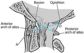 Figure 139.3.
Powers’ ratio: if BC/OA is greater than 1, then an anterior
occipitoatlantal dislocation exists. Ratios less than 1 are normal
except in posterior dislocations, associated fractures of the odontoid
process or the ring of the atlas, and congenital anomalies of the
foramen magnum. (Redrawn from Jarrett PJ, Whitesides TE Jr. Injuries of
the Cervicocranium. In: Browner BD, Jupiter JB, Levine AM, et al, eds. Skeletal Trauma: Fractures, Dislocations, Ligamentous Injuries, Vol 1. Philadelphia: W.B. Saunders Co., 1992:668, with permission.) -
The lateral roentgenogram also defines
the atlanto–dens interval (ADI), which should be 3 mm or less in adults
and 5 mm or less in children (32). -
Actual radiographic visualization of dens
fractures may be difficult on the lateral roentgenogram. However, the
angle of the dens with reference to the vertebral body
P.3668
of
C-2 should be evaluated. Angles exceeding 20° should probably be
considered abnormal or at least suggestive of a fracture and requiring
additional evaluation. -
Fractures of the posterior arch of C-1
are generally visible on the lateral roentgenogram, but significant
angulation of the posterior arch may be the only visible sign when the
fracture line is in close proximity to the lateral mass of C-1.
can be visualized and fully defined on the plain lateral radiograph.
Vertical distraction injuries at either occiput–C1 or at C1–C2 are
easily visualized on the lateral roentgenogram and are most clearly
defined on that study. Finally, the lateral roentgenogram can also be
of some value in assessing the retropharyngeal soft-tissue shadow (68,85).
The prevertebral soft tissue anterior to C-1 is clearly thicker than
that more distal in the cervical spine. An increase in prevertebral
soft-tissue shadow may not be present within the first hour or two of
injury and is a quite unreliable sign in an uncooperative or screaming
or crying patient. Soft-tissue shadows anterior to C-1 of greater than
10 mm in a cooperative patient suggest that there is some anterior
column injury causing bleeding into the retropharyngeal space. This
finding, in combination with a posterior arch fracture at C-1, would
suggest that there is an anterior element injury as well.
is to look for contiguous or noncontiguous injuries in the cervical
spine (55). Injuries in combination usually
have the same mechanism of injury. The initial lateral roentgenogram
may reveal an associated injury in 22% to 50% of patients, depending on
the pattern and severity of the upper cervical injury.
evaluation of the upper cervical spine than it does to the evaluation
of the lower cervical spine. However, the posterior elements of C-1 and
C-2 can be visualized with this view. One of the more critical features
is to assess the orientation of the spinous processes. Loss of
alignment of the spinous processes is highly suggestive of a rotatory
injury in the upper cervical spine. In addition, an angular deformity
on the AP roentgenogram may also be helpful, especially in patients
with torticollis, for whom the lateral may be extremely difficult to
assess. The AP is also helpful for assessing concurrent injuries in the
lower cervical spine.
condyles, may show evidence of a fracture of the occipital condyles,
and also gives an excellent view of the lateral masses of C-1.
Spreading of the lateral masses of C-1 is indicative of a fracture of
the anterior arch of C-1, as seen in Jefferson’s fractures. The total
displacement of the lateral masses can be evaluated (80),
providing an indication of rupture of the transverse ligament. The
radiographic appearance of a rotatory subluxation at C1–C2 is often
defined on the open mouth radiograph with the so-called “wink” sign
[overlapping of the inferior edge of the lateral mass of C-1 and the
superior edge of the lateral mass of C-2, thus apparently eliminating
the joint space (31)]. The odontoid–lateral
mass relationship (distance from lateral mass to dens on each side),
which sometimes is cited as a pathologic sign, is, in fact, asymmetric
in many normal individuals and is of little significance (52,67).
delineation of fractures that have already been identified. Make the
slices at a 1.5 or 2 mm interval to enhance coronal and sagittal
reconstructions and three-dimensional reconstructions. In fractures of
the atlas, the gantry of the CT scanner must be parallel to the arch of
C-1. If care is not taken with the orientation, the views will be
difficult to interpret and not add much information to the plain
radiographs. At C-1, the CT scan is most helpful in defining the nature
of injuries involving the ring. For injuries of the transverse
ligament, CT scanning is of help where the disruption of the transverse
ligament is with a bony avulsion. In those dens fractures in which the
fracture line is not clearly visualized on either the AP or the lateral
plain radiographs, but an angular deformity of the dens is noticed, a
CT scan with midsagittal reconstructions may define the injury. CT
scanning is also helpful for defining dens anatomy before screw
fixation (44). It is excellent in defining abnormal C1–C2 relationships, especially in rotatory dislocations and subluxations (21,50,61,63), and as defined by Sonntag and Dickman (79), the CT scan with appropriate reconstruction may also help define the
position of the vertebral artery and determine whether placement of an atlantoaxial screw is possible in both sides.
useful. It has recently been used to allow direct visualization of the
transverse ligament, especially in patients with head injuries. The
gradient echo MRI pulse sequence is of greatest value (18).
Although MRI is helpful in delineating compression injuries to the
brain stem and spinal cord in the upper cervical spine, it is of less
value than the CT scan in defining bony anatomy. Because the majority
of concerns in upper cervical spine trauma are about bony anatomic
relationships, the role of MRI remains limited.
injury, or those who are suspected of having a spine injury, will
usually present to the emergency facility immobilized in a collar and
on a spine board. Continue this immobilization until the spine has been
cleared or until definitive immobilization and treatment can be
instituted. Most upper cervical spine injuries in patients without
neurologic deficit can be continuously immobilized in a collar until
evaluation by CT scan and MRI is completed. Thus, a neurologically
intact patient with a posterior arch fracture who is suspected of
having a Jefferson fracture may undergo a CT scan using collar
immobilization. In contrast, some place patients with transverse
ligament rupture and a Brown–Séquard lesion in traction immobilization
before initiating any further radiologic studies. It is our preference
to keep the patient immobilized in a Philadelphia collar or Miami J
collar and not to convert the patient to traction until the workup is
completed. This makes transfer into the imaging machinery easier. With
transfer in and out of a CT scanner or MRI machine, any traction will
generally need to be discontinued several times, with some additional
risk to the patient. Furthermore, it is critical with certain injuries,
such as traction injuries to the upper cervical spine, that traction
not be applied at all. If this mechanism is not recognized, even
traction weights as small as 10 lb can cause stretching of the brain
stem or cord with additional neurologic injury.
apply once the radiologic examination is completed. The decision
depends on two factors: What personnel are available to apply the
traction device? What is the goal of applying the device to the
patient? It is far simpler and more expeditious in the emergency
setting to place Gardner–Well tongs, because this procedure can be done
accurately by one person in a very short period of time and with
minimal movement of the patient. Placement of a halo ring requires
precise positioning of the patient and a surgeon and an assistant to
make sure that the ring is applied properly. If the goal is simply to
apply a traction force to either reduce or stabilize an injury before
surgery, in which the surgical procedure will give definitive
stabilization not requiring postoperative immobilization in a halo
vest, Gardner–Wells tong traction is preferred. In contrast, in
injuries that require initial reduction by traction and that will
either be treated definitively in a halo vest or treated by surgery
most likely will require additional postoperative immobilization in a
halo vest, initial placement of a halo is appropriate. A third group of
patients—those with distraction injuries to the cervical spine, such as
occiput–C1 dissociations or type IIA traumatic spondylolisthesis of the
axis—will be placed in a halo and then immediately in a halo vest for
stabilization. No traction is indicated in either of those injuries but
ensuring stability is important.
in a supine position or whether the erect position is safe, which
simplifies the placement. Patients with grossly unstable injuries or
multiple injuries cannot tolerate a sitting position, and thus require
application in the supine position using a head-positioning apparatus
and an open ring halo to allow accurate placement. In those patients
who have an isolated upper cervical spine injury, such as a minimally
displaced dens fracture, the halo ring can be applied by applying a
cervical collar and placing the patient in the sitting position, for
placement of the ring and, subsequently, the vest.
-
Apply cervical tongs, such as
Gardner–Wells tongs, in the supine position. Cleanse the hair directly
above the external auditory meatus of the ear with povidone-iodine
(Betadine) solution, but shaving the patient’s hair is not necessary. -
Place the sterile pins through the ring
and insert at a site directly superior to the external auditory meatus
and one fingerbreadth above the pinna. Before application of the tong,
inject the area down to the periosteum of the skull with 1% lidocaine,
usually with epinephrine (1:100,000). -
Do not incise the skin. Tighten the pins
simultaneously and, depending on the manufacturer’s recommendations,
bring the pressure indicators either to the level of outer surface of
the pin or approximately 1 mm beyond. -
The initial traction weight in an adult
is generally 10 lb, but before adding any weight, ascertain that the
injury will not be made worse by traction. -
Increase the weights incrementally and
obtain an appropriate radiograph between each increase to ensure that
overdistraction is not occurring.
cervical level above the fracture, with an initial 10 (4.6 kg) to 15 lb
(6.8 kg) to overcome the friction of the head on the bed has been
suggested, this is often not enough to reduce
certain
cervical spine injuries. The weight in certain types of traumatic
spondylolisthesis as well as Jefferson’s fractures will need to be
increased to as much as 30 lb (13.6 kg) before an acute injury can be
reduced. Between each 5 lb (2.3 kg) increment, however, appropriate
radiographic evaluation is critical.
-
Before placing the ring, measure the head and torso and size for the halo and vest according to the manufacturer’s instructions.
-
Place the patient in the supine position
or an operating table and use either a mechanical head holder or
positioner, or apply the halo with the patient in the sitting position. -
Select the pin sites carefully; four pin
sites are adequate in the adult, but more may be needed in the elderly
patient with a thin skull or in the child. -
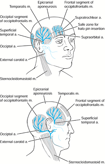
The preferred sites for halo insertion have been determined by a series of radiographic, cadaver, and clinical studies (36):
Anteriorly place the pins approximately 1 cm superior to the orbital
ridge, below the equator of the skull, and over the lateral two-thirds
of the orbit. This will generally avoid the temporalis muscle, the
supra-orbital branch of the trochlear nerve, and the frontal sinuses (Fig. 139.4).![]() Figure 139.4.
Figure 139.4.
The “safe zone” for placement of halo fixator pins. Place the anterior
pins anterolaterally, approximately 1 cm above the orbital rim, below
the equator of the skull, and cephalad to the lateral two thirds of the
orbit. The safe zone avoids the temporalis muscle and fossa laterally,
and avoids the supraorbital and supratrochlear nerves and the frontal
sinus medially. (Redrawn from Ballock RT, Botte MJ, Garfin SR.
Complications of Halo Immobilization. In: Garfin SR, ed. Complications of Spine Surgery. Baltimore: Williams & Wilkins, 1989, with permission.) -
Place the pins as far laterally as
possible to minimize prominent scarring. Avoid placement within the
temporalis muscle and fossa because it is particularly painful with
motion and could cause significant bleeding; in addition, the area has
a very thin cortical base, making perforation more common. -
The posterior sites are less critical and
are generally placed at 180° on the contralateral side. Any area 2 to 3
cm posterior to the edge of the pinna of the ear is generally
satisfactory. Shave the areas so that hair is not trapped as the pin is
placed. -
Prepare and anesthetize each pin site by
passing the needle for the local anesthetic through the selected hole
or from above the halo to the exact contact point on the skin.
Infiltrate the skin and deep tissues down to the skull. -
Ask the patient to close his or her eyes,
and then make a small vertical incision with a #11 blade, directly in
line with the selected screw holes. Some surgeons place the pins
without using skin incisions (10). Place the
four pins through the halo and screw them into the small incisions.
Tighten the pins in a sequential fashion so that the halo is not
shifted by overtightening one side before tightening the other. -
Tighten the pins in 2-inch-pound
increments to a maximum of 8 inch-pounds in the normal adult skull.
Tighten to lower levels when multiple pins are used in either the child
or the osteoporotic elderly adult (9). Although
6 inch-pounds were initially used, 8 inch-pounds appears to have a
lower rate of complications in terms of loosening and infection (9). -
Once the optimal torque is achieved with
a torque screwdriver or a disposable wrench, place lock nuts over the
pins and tighten them to prevent backing out of the pins. -
Now check the reduction of the cervical
spine with a radiograph with the patient supine, if applied in the
supine position, and then obtain a second radiograph in the upright
position to be certain that the reduction does not shift. Obtain
another upright roentgenogram 24 hours after the patient is allowed to
ambulate, to ensure the maintenance of position. Subsequent adjustments
to the halo, in terms of position of the fracture, should be done in
the upright position for optimal vest fit. -
With a torque wrench, retighten all four
pins in the halo at 24 hours back to 8 inch-pounds. Teach the patient
to cleanse the pin sites daily and to inspect for any problems.
number of different ways, although it is probably easiest to classify
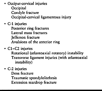
them by level as opposed to any type of mechanistic classification (Table 139.1).
 |
|
Table 139.1. Classification of Injuries by Cervical Level
|
extremely rare and often are fatal. This group of injuries includes
dislocations that can occur with or without occipital condyle
fractures, as well as occipital condyle fractures that occur without
any subluxation. In addition, there are pure distraction injuries at
the occipital–cervical junction. These are the most commonly fatal.
These injuries may be overlooked in the acute emergency because they
are uncommon and difficult to diagnose on plain roentgenograms. Many of
these injuries are found only at autopsy (3).
The injuries are commonly associated with other noncontiguous cervical
spine fractures and with head injuries. The presence of a high-level
neurologic deficit, often with involvement of all four extremities plus
abnormal respiratory function, known as “pentaplegia,” is a tipoff to
injury at the occipital–cervical junction. As a group, these injuries
most commonly result from high-speed motor vehicle accidents or are
found in pedestrians struck by motor vehicles (3,4,51,53,56,78,86).
The cause of death may be due to the associated head injury or sudden
loss of voluntary respiratory function because of brain stem injury
from the occipital–cervical dissociation (53).
a higher rate of survival than occipital–cervical dissociations or
dislocations. Patients may present with cranial nerve involvement as
well as persistent occipital headaches. The mechanism of injury of all
occipital condylar fractures is believed to be either sudden
deceleration or direct axial loading on the cranium. Occipital–cervical
dislocations can occur as a result of violent hyperextension or
distraction forces in which the torso is pinned in position and the
distraction force applied to the neck by a force applied beneath the
patient’s chin. Occipital condyle fractures have been characterized by
Anderson and Montesano (4) (Fig. 139.5). A type I fracture (Fig. 139.5A)
is a unilateral undisplaced, comminuted fracture of the condyle,
usually resulting from axial impact between the skull and the axis. The
alar ligament may be disrupted on that side, but the segment is usually
stable. A type II fracture (Fig. 139.5B) is a
unilateral occipital condyle fracture that is associated with a basilar
skull fracture on the same side. The mechanism is generally axial
loading with lateral bending, and this injury is generally stable. Type
I and II injuries can be treated nonoperatively using a rigid cervical
orthosis for 6 to 8 weeks; halo mobilization is not generally required.
The type III fracture (Fig. 139.5C) is a
unilateral alar ligament avulsion from the occipital condyle. It occurs
as a result of extreme lateral bending, rotation, or a combination of
the two. This injury, because it has a ligamentous component, may be
associated with atlanto-occipital dislocations. Type III fractures may
be unstable. Treatment is based on the degree of instability, ranging
from collar immobilization, to halo immobilization, to posterior
occipital–cervical fusion if associated disruption of the occiput–C1
complex is significant. Perform flexion-extension radiographs at the
end of nonoperative management to assess the degree of stability. At
that
point,
abnormal motion can be considered evidence of either nonunion or
nonhealing of the ligamentous injuries, which requires treatment with
an occipital–cervical fusion. Occipital condyle injuries are commonly
unilateral but may be bilateral as well.
 |
|
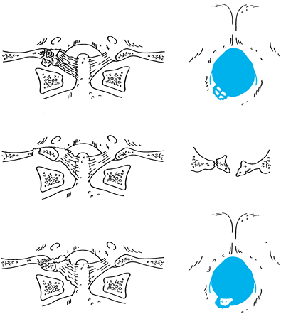
Figure 139.5. The classification of Anderson and Montesano describes three basic types of occipital condyle fractures. A:
An impaction-type fracture, which is usually the result of an asymmetrical axial load to the head; it may be associated with other lateral mass fractures in the upper cervical spine. B: A basilar skull-type occipital condyle fracture. C: An avulsion-type occipital condyle fracture, which may be the result of a distraction force applied through the alar and apical ligament complex. (Redrawn from Anderson P, Montesano P. Morphology and Treatment of Occipital Condyle Fractures. Spine 1988;13:731, with permission.) |
been incorporated into a single classification described by Traynelis
et al. (86) (Fig. 139.6).
Type I injuries are anterior dislocations and generally have the
highest survivability. Type II injuries demonstrate vertical
displacement, usually from a distraction mechanism: type IIa injuries
occur at the occipital–cervical junction, and type IIb injuries occur
between the atlas and axis. In some cases, these injuries may be
combined injuries. When there is greater than 2 mm of vertical
displacement between the occiput and C-1 (IIa), a rupture of the
tentorial ligament and alar ligaments must be suspected. At the C1–C2
level (IIb), the joint capsule is usually involved as well as the
tentorial membrane and the alar ligaments. Injuries to the transverse
ligament can also occur. Type II injuries should not be placed in
longitudinal traction. Type III injuries are posterior dislocations and
are often fatal, although accompanying fracture of the C-1 arch may
increase the chance of survival. Types I and III injuries may be
realigned initially using traction, although the degree of ligamentous
disruption is difficult to assess initially. Traction should be used
only in type I and type III injuries, with traction restricted to
between 2 (0.9 kg) and 5 lb (2.3 kg). Interestingly, gravity itself is
usually sufficient to reduce any translation. Increased survival has
been reported with traction (26). After closed
reduction is achieved, immediately place the patient in a halo vest and
obtain a CT scan to identify any fractures. After this assessment,
treat only patients with minimal ligamentous destruction and minimal
bony disruption definitively in a halo vest for a period of 3 months.
At the conclusion of that time, perform flexion-extension
roentgenograms to check stability and decide whether a
occipital–cervical fusion is necessary based on the degree of residual
translation.
 |
|
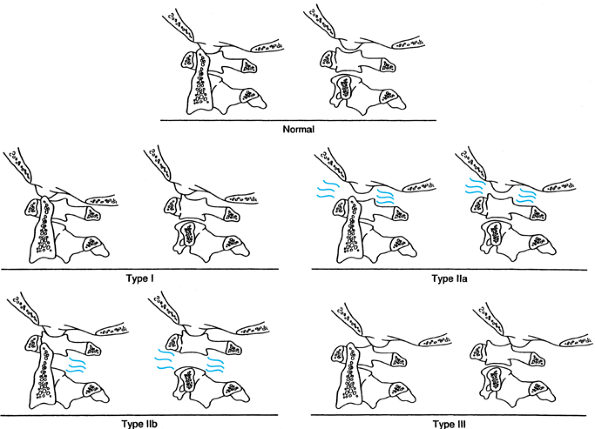
Figure 139.6.
The classification of Traynelis and others takes into account both the direction and level of upper cervical dislocation. Type I injuries (antero-occipital–cervical dislocations) are more common than type III, but both are easily missed on routine radiographs. Type II injuries are distraction types, with type IIa occurring predominantly at the occipitoatlantal level and type IIb occurring at the atlantoaxial level. Not accounted for in this classification are double-level distraction injuries, which are uniformly fatal. Type III injuries, which are quite infrequent, are posterior atlantooccipital dislocations. (From Levine AM, Eismont FJ, Garfin SR, Zigler JE. Spine Trauma. Philadelphia: W. B. Saunders Co., 1998, with permission.) |
injuries and a posterior occipital–cervical fusion is indicated.
Various techniques have been used to achieve an occipital–cervical
fusion. The most rigid fixation involves the use of a contoured plate
secured with multiple occipital screws and a C1–C2 transarticular screw
(24,38,39) (Fig. 139.7). Techniques for occipital–cervical wiring, described by Wertheim and Bohlman (90), require postoperative immobilization in a halo vest, but in their series, all 13 patients developed a
solid arthrodesis. Other techniques using corticocancellous struts
wired into the skull and beneath the spinous processes of C-1 and C-2
similarly have had high rates of union with minimal loss of fixation in
patients treated postoperatively in a halo vest. A contoured
occipital–cervical rod has also been described by a number of authors,
giving additional stability that is not provided by bone graft alone (73,79).
Irrespective of the type of construct, overall fusion rates for
occipital–cervical fusions, when properly immobilized postoperatively,
are in excess of 90%.
 |
|
Figure 139.7.
Lateral view of the occipitocervical plating technique using C1–C2 transarticular screws and titanium reconstruction plates with bicortical cranial screws. |
-
With the patient in the traction applied
at the time of admission, perform an awake fiberoptic intubation. Then
turn the patient into the prone position while still awake. -
Use a three-pin Mayfield (Ohio Medical
Instrument Co., Inc., Cincinnati, OH) or halo modified headrest to
secure the head. Induce general anesthesia once appropriate positioning
is obtained and the patient’s neurologic status is reassessed and found
to be unchanged. -
Any manipulation of the head is done
before inducing general anesthesia. Avoid extreme positions of flexion
or extension because the plate fixation is rigid. -
Set up fluoroscopy so that AP and lateral images can be easily obtained, preferably simultaneously with two machines.
-
Make a posterior incision from the
occipital prominence and extend it to the midcervical spine. Elevate
all soft tissue off the bone from the greater occipital prominence to
the C2–C3 joint. -
Select two plates with appropriate hole
spacing and then contour them to fit the occipital–cervical junction,
with at least three fixation holes available in the occiput and
extending far enough distally to allow a C1–C2 transarticular screw to
be placed on each side. -
Take care in contouring the occipital
portion of the plates so that the terminal end is not prominent and the
screw fixation is on the undersurface of the occiput rather than on its
most prominent posterior portion. -
After templating and drilling the C1–C2 transarticular screw according to the technique described by Magerl and Seemann (Fig. 139.7 and Fig. 139.12) (59),
select the appropriate-length screw, place the plate into position, and
pass the transarticular screw through the plate, tightening it so that
the plate lies in the appropriate position against the occiput on one
side.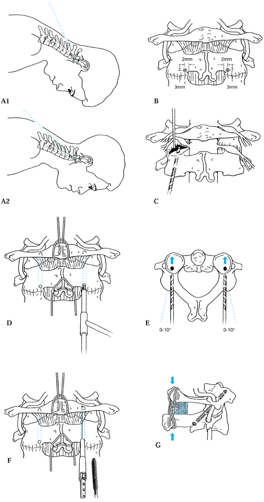 Figure 139.12. The C1–C2 fusion technique of Magerl. A1, A2, B to F: The surgical technique; see text for details. G: Lateral view of the completed fixation. [Redrawn from (parts C and G) the Barrow Neurological Institute, Phoenix, AZ and (parts A and B, and D to F) from Levine AM, Eismont FJ, Garfin SR, Zigler JE. Spine Trauma. Philadelphia: W. B. Saunders Co., 1998, with permission.] The C1–C2 fusion technique of Magerl. A1, A2, B to F: The surgical technique; see text for details. G: Lateral view of the completed fixation. [Redrawn from (parts C and G) the Barrow Neurological Institute, Phoenix, AZ and (parts A and B, and D to F) from Levine AM, Eismont FJ, Garfin SR, Zigler JE. Spine Trauma. Philadelphia: W. B. Saunders Co., 1998, with permission.]
 -
Then place the occipital screws using
three bicortical screws per side. The screws are typically between 6
and 12 mm in length. In older patients, the dura may be adherent to the
inner surface of the skull, causing a small cerebrospinal fluid (CSF)
leak, but this can be easily stopped by simply placing the screw in the
hole. -
Then apply the second plate in a similar fashion.
-
Fashion a corticocancellous graft to lie
between the two plates, covering the posterior portion of the occiput,
the posterior arch of C-1, and around the spinous process of C-2. Hold
this graft in place using heavy suture or wire. -
If transarticular screw fixation cannot
be achieved because of the patient’s position, alternatively, a C-2
pedicle screw can be placed, generally in combination with a C-3
lateral mass screw and a wire or suture placed around the arch of C-1
and tied to the plate on either side. -
Immobilize the patient postoperatively in
a rigid collar for 12 weeks. While the patient is in the collar, be
certain that he does not develop an occipital decubitus either because
of the cervical spine trauma resulting in anesthesia in the area of the
greater occipital nerve or as a result of the surgical dissection.
associated with a second fracture, and approximately 25% of them are
associated with noncontiguous second fractures. The two most common
types of fractures associated with a fracture of the atlas are
fractures of the dens (27,55,58) or type I traumatic spondylolisthesis (55).
Because the majority of injury patterns for fractures of the atlas
involve widening of the space available for the cord rather than
narrowing of the canal area, these injuries are not generally
associated with neurologic deficit. If a deficit is present, its
etiology may be from another associated or nonassociated spine or head
injury. Multiple types of fractures of the C-1 arch have been
identified (Fig. 139.8). The initial description of fractures of the C-1 arch was by Jefferson (48,49).
He described isolated fractures of the posterior arch as well as
multiple fractures of the arch, although his name is most associated
with the four-part fracture. Segal et al. (77)
have actually identified six different fracture patterns. However, the
most common injury type is the posterior arch fracture. This is thought
to be the result of a hyperextension-axial loading injury in which the
posterior arch is pinched between the occiput and the ring of C-2 (92).
These fractures tend to occur at the area just behind the lateral mass
where the vertebral artery passes over it. Associated with this
hyperextension-axial load mechanism of injury are other fractures that
have a similar mechanism, such as posteriorly displaced dens fractures,
type I traumatic spondylolisthesis of the axis, and C-2 anterior
extension teardrop fractures.
 |
|
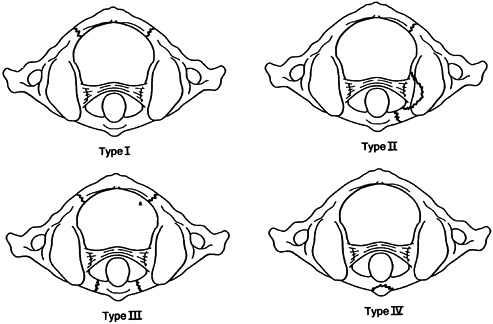
Figure 139.8.
Four major types of fractures can occur at the level of the atlas. Type I is the most common and is a posterior arch fracture, which is the result of hyperextension and axial loading. It may be associated with other injuries caused by the same mechanism, such as traumatic spondylolisthesis. Type II, or lateral mass fracture, is the result of axial loading and lateral bending. There is usually a fracture line anterior and posterior to the lateral mass, causing asymmetric spreading. A second fracture line can also be present in the contralateral posterior arch. Type III, or Jefferson’s fracture, is a burst fracture resulting from axial loading of C-l. Two to five fracture lines can be present, although most commonly there are four fracture lines: two in the anterior arch and two in the posterior arch. The final category, type IV, is an avulsion fracture of the anterior tubercle of the atlas. (From Levine AM, Eismont FJ, Garfin SR, Zigler JE. Spine Trauma. Philadelphia: W. B. Saunders Co., 1998, with permission.) |
mass fracture, is generally composed of a fracture anterior to the
lateral mass and one posterior to the lateral mass. In some instances,
there may also be a fracture through the posterior arch on the
contralateral side (42,55).
These fractures have the same degree of instability, whether they are
two-part or three-part injuries. The mechanism of injury is an axial
load with lateral bending. The presence of a second fracture on the
contralateral side would suggest at least some slight extension
associated with this injury. In addition, the most common fracture
occurring in association with this type is a lateral mass fracture in
the lower cervical spine, which also has the same mechanism of
extension, axial loading, and lateral bending.
Jefferson fracture, which is a classic bursting injury of the ring of
C-1. It has variably been described as having two fractures, one in the
anterior arch and one in the posterior arch; or having three fractures,
one in the anterior arch and two in the posterior arches; or having
four or five fractures, with at least two in the anterior arch and two
in the posterior arch. On open mouth radiograph view, this generally
shows symmetric displacements of the lateral masses of C-1 (43,48,49,55,77).
The injury is believed to be the result of axial loading applied to the
skull. Because the lateral masses of C-1 are wider laterally than
medially, they act like a wedge when they are axially loaded, driving
the lateral masses laterally and disrupting the ring. Splaying of the
lateral masses more than 6.9 mm on an open mouth view may indicate
disruption of the transverse ligament (80).
the inferior portion of the anterior tubercle of C-1, where the longest
colli muscle inserts. It is generally the result of hyperextension and,
therefore, is an avulsion injury. It is completely stable (83). The final type of injury is a transverse process fracture, which may be either unilateral or bilateral (15).
treated nonoperatively with 6 to 12 weeks of immobilization in a hard
collar. Nonunion is exceedingly rare (55,77).
Patients who have a dens fracture in association with a posterior arch
fracture cannot be stabilized by standard C1–C2 wiring techniques.
Without the integrity of the posterior arch, either an anterior dens
screw or a posterior transarticular C-1 atlantoaxial arthrodesis may be
necessary when operative treatment is indicated. Avulsions
from
the anterior tubercle and transverse process fractures can be treated
symptomatically with simple collar immobilization until pain relief is
achieved.
into two groups: those that are only minimally to moderately displaced
(less than 7 mm total displacement on an open mouth view) and those
that are more significantly displaced. Controversy remains concerning
the most effective treatment for these injuries. For minimally to
moderately displaced fractures, the transverse ligament is intact.
Immobilization in a hard collar for less significantly displaced
injuries or immobilization in a halo vest for more significantly
displaced injuries appears to give adequate long-term results. The most
common complications of treating these patients is symptomatic nonunion
(77) in those patients who have displaced
fragments of the ring that do not unite. If the fragments are
symptomatic, they may require arthrodesis. Remember that the halo and
vest cannot be expected to reduce the ring fragments, even with
traction. Once traction is removed, the original displacement will
recur. Thus, placing the patient in traction for several days before
immobilizing the patient in a halo vest does not improve the degree of
displacement (42,94).
and, therefore, more than 7 mm displacement on an open mouth
radiographic view can be treated in one of two ways. Although it was
initially thought that these patients would have long-term instability
without surgical intervention, on the basis of the apparent rupture of
the transverse ligament (75), this has turned out not to be the case (51).
Thus, if the patient can achieve union of the ring of C-1, the degree
of instability, after treatment, is limited. As demonstrated earlier by
Fielding (29), this is because only the
transverse ligament is ruptured, and the alar, apical, and accessory
ligaments as well as the joint capsule are still intact and providing
sufficient stability. Thus, the degree of C1–C2 instability is minimal
when the ring heals solidly (55). Therefore,
patients can be treated with enough longitudinal traction to reduce the
splaying of the lateral masses to anatomic position and then held in
longitudinal traction until early healing takes place (approximately 6
weeks). Once preliminary healing has occurred, the patient can be
mobilized in a halo vest for an additional 6 weeks without risk of loss
of reduction.
then the patient is immediately mobilized (within the first week),
reduction will be lost. Because of the long hospitalization required,
long-term traction is less popular than it was previously. In addition,
if the patient cannot be left in a supine position on a Stryker
(Stryker Corp., Kalamazoo, MI) frame for long periods of time,
operative treatment for significantly displaced fractures may be
indicated.
Jefferson’s fracture is the modified Magerl transarticular C1–C2 screw
fixation. The technique, however, has to be modified over that
originally described by Magerl and Seemann (Fig. 139.9) (59)
because a considerable portion of the stability of the technique is
with the bone block that is usually placed between the intact posterior
arch of C-1 and the spinous process of C-2. Because a Jefferson’s
fracture has an incompetent C-1 arch, additional stress is placed on
the screws, risking early failure of fixation. Therefore, denude the
cartilage of the facet joints, and pack bone directly into the
posterior aspect of the C1–C2 joint. Also, place graft between the ring
of C-1 and C-2, recognizing, however, that its structural integrity is
compromised. Postoperatively, additional immobilization may be
necessary in the form of a rigid collar or a halo vest, depending on
the original degree of instability, the quality of the patient’s bone,
and the quality of the fixation.
 |
|
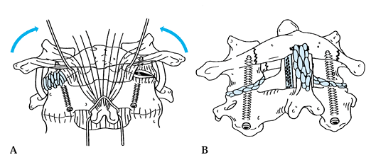
Figure 139.9.
An alternative method for the treatment of a widely displaced lateral mass or Jefferson’s fracture is the Magerl transarticular C1–C2 screw fixation. See text for details. |
-
Reduce the fracture with halo traction
using about 30 to 35 lb (13.6 to 15.9 kg) of traction to achieve an
anatomic reduction, which makes placement of the screws relatively
straightforward. Further reduction is not possible once operative
stabilization has begun. Use a biplanar fluoroscope imaging. -
The only variation in the standard technique is that the joints are fully exposed (Fig. 139.9A)
so that the cartilage can be curetted out for fusion, and no fixation
of bone graft is possible between the fractured arch of C-1 and the
lamina of C-2. -
Graft directly into the facet joints and also do an onlay graft from C-l to C-2 (Fig. 139.9B)
so that as healing occurs, a solid arthrodesis will also occur. With
satisfactory screw fixation, either the halo vest can be continued
postoperatively or hard collar can be used.
satisfactory fusion, long-term results in terms of stability are
excellent. In patients with relatively undisplaced lateral mass
fractures and Jefferson’s fractures treated only in a collar or halo
vest, late instability is rare if union is achieved between all
fragments (55,77). The motion between C1–C2 however rarely returns to normal. In the Levine and Edwards series (55), up to 80% of patients had some residual neck pain, although none required secondary fusions for neck pain (55).
The significant joint incongruity and resultant degenerative changes in
fractures that are significantly displaced at the conclusion of
treatment will commonly lead to pain and secondary occipital cervical
fusion. In one study, nonunions occurred in 17% of patients (77),
and nonunion was directly related to the amount of displacement.
Patients with a nonunion and displacement of the posterior arch could
sustain neural compression on the basis of the displaced fragment, but
this is a rare complication.
congenital abnormalities, infection, and arthritis. Traumatic
atlantoaxial instability can be of two types. It can be related to
flexion instability with anterior translation of the atlas on the axis
resulting from rupture of the transverse ligament and disruption of the
secondary stabilizers—the alar, apical, and accessory ligaments. The
second type of atlantoaxial instability is a rotatory instability,
which can be of several different types and be the result of both bony
and ligamentous injuries. The transverse ligament is the primary
stabilizer, preventing anterior translation of C-1 on C-2, but the
alar, apical, and accessory ligaments, as well as the capsular
ligaments, offer secondary stabilization. Posterior translation of C-1
on C-2 is prevented by the impingement of the anterior ring of C-1 on
the dens. As shown by early work by Fielding et al. (29),
a maximum of 3 mm of anterior translation of C-1 on C-2 can occur with
an intact transverse ligament in the adult. Within the range of 3 to 5
mm of translation, catastrophic failure occurs, usually within the
midsubstance of the ligament rather than at the bony attachments. No
correlation has been made between the strength of the transverse
ligament and age other than that children tend to be slightly more lax
and, therefore, an ADI of 5 mm of translation can be accepted in
children as normal. Simple experimental sectioning of the transverse
ligament without disruption of the alar, apical, and accessory
ligaments results in an ADI of only 5 mm in the adult in the
experimental setting (29). In patients with
gross instability with an ADI greater than 10 mm, not only does the
transverse ligament need to be sectioned but all of the secondary
restraints as well.
trauma to the head, although they may occur in older patients with a
simple fall and striking of the occiput. Patients may have varying
neurologic involvement, from being neurologically normal with severe
neck pain to a transient quadriplegia to a Brown–Séquard–type syndrome.
The diagnosis of this injury is generally made on a lateral
roentgenogram. If roentgenograms are taken in the supine position, the
subluxation may reduce, especially in a patient whose chest is
disproportionately large in relation to his or her head, thus placing
the patient in extension, as is frequently the case with children. If
the patient does not have neurologic deficit and injury is suspected,
physician-supervised flexion-extension films in the alert, awake,
neurologically intact, cooperative patient may be very helpful in
making the diagnosis. In contrast, if the patient has severe neck pain
and paraspinous muscle spasm, adequate-quality flexion-extension films
may not be attainable. There may not be enough motion in the cervical
spine to indicate whether the patient has instability. In that case,
several options are available. The patient may be simply immobilized in
a hard collar, and when the spasm subsides, adequate flexion-extension
films can be obtained. Alternatively, under physician supervision, the
amount of spasm in the paraspinous musculature can be reduced by
intramuscular injection, allowing flexion-extension roentgenograms to
be taken. An MRI may be used to investigate the integrity of the
ligamentous complex.
which its insufficiency is the result of the avulsion from its
insertion on the lateral mass, is uncommon. This is one of the few
injuries in the upper cervical spine that routinely requires surgical
intervention. There are a variety of techniques to achieve C1–C2
arthrodesis. These are commonly done by posterior arthrodesis because
it is infrequent to have a fracture of the posterior arch and a rupture
of the transverse ligament from a flexion type injury. C1–C2 fusion,
using either a Gallie (35), Brooks (12), or
a Magerl (46) C1–C2 transarticular screw fixation, will give satisfactory results in this situation.
With any method, significant loss of rotation at the atlantoaxial joint
will occur postoperatively because 50% of neck rotation normally occurs
at this joint. In fact, because of compensatory motion at other joints,
the loss is often less, as reported by Fielding et al. (30).
Fielding demonstrated that an average loss of only 13% of rotational
motion occurred in patients younger than 20 years of age; a 25% loss
occurred in those in the 20-to-40-year-old age group, and a 28% loss
occurred in those older than 40 years of age.
 |
|
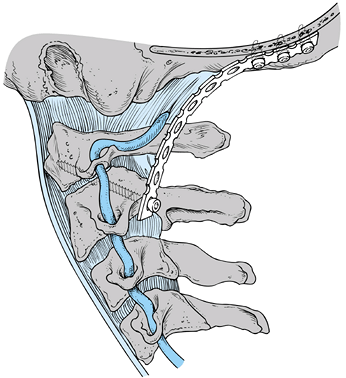
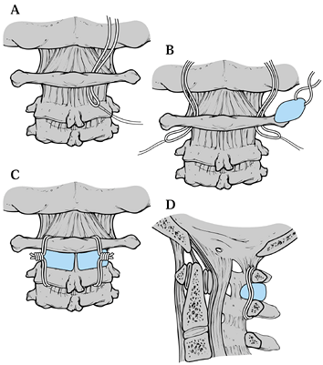
Figure 139.10.
Brooks fusion: The occipital nerves emerge through the interlaminar space between the atlas and the axis, the vertebral arteries are more lateral. See text for a description of the surgical technique. (Redrawn from Jarrett JP, Whitesides TE Jr. Injuries of the Cervicocranium. In: Browner BD, Jupiter JB, Levine AM, et al, eds. Skeletal Trauma: Fractures, Dislocations, and Ligamentous Injuries, Vol 1. Philadelphia, W. B. Saunders Co., 1992:689, with permission.) |
passed beneath the arch of C-1, around the spinous process of C-2 in
the Gallie technique and sublaminarly beneath the arch of C-2 in the
Brooks technique. With the Gallie technique, a corticocancellous bone
lock is laid on the arch of C-1 and notched to fit around the spinous
process of C-2. There are a number of different modifications of the
Brooks technique, ranging from two wedge-shaped blocks (Fig. 139.10),
one on each side, with a single wire around them, to two wires around
them, to instances of a single block in the center with wires that pass
beneath the laminar at C-1 as well as sublaminar at C-2.
space between the atlas and the axis; the vertebral arteries are more
lateral.
-
Make a midline approach. The arteries and nerves are fairly well protected by the neck muscles. Expose C-1 and C-2.
-
On both the right and left, pass sutures under the posterior arch of the atlas (Fig. 139.10A).
Then pass the sutures on the lamina of C-2. A twisted wire is then tied
to the suture, which is used to guide the wire under the arch of the
atlas and the lamina of the atlas (Fig. 139.10B). -
In the Figure 139.10C
the wires are now in place and lie anterior to the anterior portion of
the atlantoaxial membrane, which was not removed during exposure of the
posterior elements of the atlas and axis. -
Harvest either two iliac crest
corticocancellous grafts or one larger midline graft and fashion them
to fit between the posterior arches of C-1 and C-2. Bevel edges to fit
in the interval between the atlas and axis. Hold the graft in place
with a towel clip. When they are wired in place, the beveled edges will
be in contact with the arch of the atlas and the lamina of the axis. -
Secure the graft or grafts with the wires (Fig. 139.10D)
atlantoaxial instability. These include Down’s, Morquio’s, and
Klippel–Feil syndromes, as well as occipitalization of the atlas. The
incidence of atlantoaxial instability in Down’s patients has been
reported to be as high as 20%. There is still controversy surrounding
the need for prophylactic fusion in these individuals. Most recommend
restriction of contact activities in patients with an ADI of less than
7 mm. Prophylactic fusion is recommended for displacement of greater
than 7 mm.
and clinically by the duration of symptoms, response to treatment, or
their underlying etiology. They are most commonly due to infection or
trauma and have been reported in all age groups, with a higher
incidence in children (70) and young adults,
regardless of the etiology. The typical presentation is a sudden onset
of torticollis in which the head is rotated away and tilted anteriorly
toward the rotated side with
associated
spasm of the sternocleidomastoid muscle. The patients generally have
significant neck pain and an inability to rotate the head past neutral.
By palpating the posterior wall of the oropharynx, it is possible to
feel the difference between the normal and abnormally rotated lateral
masses. On the subluxed side, it is possible to appreciate a stepoff
from the C-1 lateral mass to the C-2 lateral mass. Any motion produces
significant discomfort. In long-standing cases, facial asymmetries may
occur. Compensation for the torticollis may occur after some time as a
result of counterrotation in the lower cervical spine or
atlanto-occipital joint.
radiograph is an obliquity in the orientation of the posterior arch of
C-1 in comparison to the remaining lower spinous processes. A widened
ADI may be seen. On the open mouth view, the anteriorly rotated lateral
mass can appear wider and closer to the midline than the opposite side.
However, the most pathognomonic sign on the open mouth view is the
“wink” sign when the inferior edge of the lateral mass of C-1 on the
affected side overlaps the lateral mass of C-2, obliterating the joint
space. On an AP view the spinous process of C-2 may be rotated away
from the side of the anterior displaced lateral mass, known as Sudeck’s
sign (84). A fixed subluxation can be easily seen on a thin-cut CT scan, which demonstrates the abnormal relationship of C-1 to C-2 (21,33,63).
The dimensional reconstructions are also very useful for complete
delineation of the injury. For reducible subluxations, a dynamic CT
scan in maximal left and right rotation will generally reveal the
deformity.
A type I deformity indicates an intact transverse ligament and a fixed
C1–C2 position within a normal range of rotation. Type II deformities
show mild deficiency of the transverse ligament with an ADI of 3 to 5
mm. Mild fixed rotation exceeds the normal motion of the C1–C2 joint. A
type III deformity has an ADI greater than 5 mm, and both lateral
masses of C-1 are displaced anteriorly, with one side rotated farther
than the other. A type IV deformity describes a posterior subluxation
of one or both lateral masses. Types III and IV have greater
instability with increased neurologic risk, and decreased success with
conservative management. Posttraumatic episodes of atlantoaxial
deformity have a higher rate of instability and require more aggressive
treatment. Rotatory dislocations of traumatic origin may have not only
ligamentous disruption but also bony avulsions or fractures from the
C-1 joint surfaces, increasing the degree of instability.
geared toward eradicating the organism responsible with intravenous
antibiotics. Treatment is then primarily based on the duration of the
deformity at presentation. If the deformity has been present for less
than 1 week, place the patient in a soft collar and put him on bed
rest. If the deformity does not spontaneously reduce, institute halo
traction. The weight initially used is based on the age of the patient:
7.7 lbs (3.5 kg) for younger children and up to 13 to 17.6 lb (6 to 8
kg) for adults. The weight may be increased in increments of 1.1 lb to
2.2 lbs (0.5 to 1 kg) every 3 to 4 days until reduction is achieved to
a maximum limit of 13.2 lb (6 kg) in children (70)
and 19.8 lb (9 kg) in adults. If the deformity has been present for
more than 1 week, start halo traction immediately. Continue traction
for up to 3 weeks, but if reduction is not accomplished, a surgical
stabilization procedure in symptomatic individuals is indicated.
devised a protocol for immobilization based on the type of deformity.
They recommend a soft collar for type I, a rigid collar for type II,
and a halo for types III and IV for a duration of up to 3 months. After
treatment, obtain flexion-extension radiographs to document stability.
evidence of significant instability or neurologic deficits, when there
is failure to achieve or maintain a reduction in an acute traumatic
deformity, or if symptoms persist after conservative treatment. A
posterior C1–C2 fusion is recommended. In situ
fusion is recommended by some, but the passing of sublaminar wires is
more difficult because of the narrowed space behind the posterior ring
of C-1. Improvement in the cosmetic deformity is usually slow and often
occurs through rotation at cephalad and caudal levels, which may become
symptomatic in the future. Some surgeons recommend an attempt at open
reduction.
-
Pass a sublaminar wire under the posterior arch of C-1 and gently applying traction in order to manually derotate the atlas.
-
After reduction is achieved, incorporate
the wire into a Gallie or Brooks C1–C2 fusion, or C1–C2 transarticular
screw fixation can be done. The C1–C2 transarticular screw fixation is
the most stable construction to prevent redisplacement if reduction can
be achieved either preoperatively or intraoperatively. -
Screw placement is difficult when residual rotatory deformity exists at the time of screw passage.
-
If neurologic deficit is present and
reduction cannot be achieved, perform a decompression of the posterior
arch of C-1, followed by an occipitocervical fusion.
of all cervical spine fractures. Neurologic deficits occur in
approximately 25% of patients with fractures and can range from
quadriplegia
to
slight neuralgias. There is a higher mortality rate associated with
this fracture in elderly patients. In younger patients, these fractures
tend to occur as a result of motor vehicle accidents; in older
patients, they tend to result from falls. The mechanism is forceful
flexion or extension with an axial load. Flexion results in anterior
subluxation, whereas extension results in posterior subluxation.
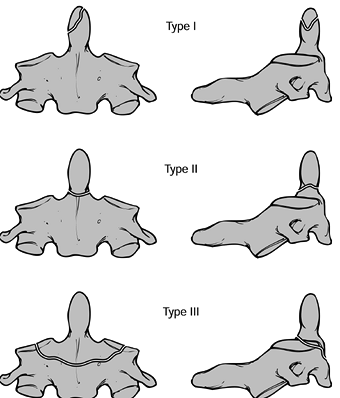
A type I fracture is an avulsion fracture at the tip of the odontoid
above the transverse ligament. A type II fracture occurs at the
junction of the body and dens, and may be transverse or oblique. A type
III fracture extends into the cancellous portion of the body of C-2.
 |
|
Figure 139.11.
Classification of odontoid fractures: Three types of odontoid fractures as seen on AP and lateral radiographs. Type I is an oblique fracture through the upper part of the odontoid process. Type II is a fracture at the junction of the odontoid process with the vertebral body of the second cervical vertebra. Type III is a fracture through the body of the axis. (Redrawn from Anderson LD, D’Alonzo RT. Fractures of the Odontoid Process of the Axis. J Bone Joint Surg [Am] 1974;56:1664, with permission.) |
immobilization with a soft collar until symptoms resolve. However a
type I fracture may be an indication of a distraction injury at C1–C2
and thus may be a grossly unstable injury requiring C1–C2 arthrodesis.
Take flexion-extension radiographs to document stability because some
instances of type I fractures are associated with other significant
ligamentous injuries that can be grossly unstable. The outcomes are
excellent, with few residual symptoms; even persistent nonunion of the
avulsion fragment offers no long-term problems.
-
Posterior displacement (19)
-
Initial displacement of greater than 5 mm (41)
-
Inability to obtain or maintain an anatomic reduction
-
Advanced patient age
-
Pre-existing diabetes or rheumatoid arthritis in the injured patient
stabilization is recommended. In addition, the inability to achieve a
reduction in traction or the inability to maintain a reduction in a
halo vest is an indication for surgical stabilization.
Nondisplaced type III injuries can be treated in a rigid collar, but
displaced injuries usually require halo vest immobilization for 12
weeks. If the fracture line is oblique, it is generally not possible to
correct collapse, but angulation can be corrected and maintained to
healing. Obtain flexion-extension radiographs at 12 weeks to document
stability. Treat failures of halo treatment with a C1–C2 fusion. Loss
of initial reduction is also an indication for fusion.
methods, as previously described. The Gallie method is not indicated
for posteriorly displaced fractures. Results of treatment of dens
fractures uniformly demonstrate an arthrodesis rate of approximately
90% irrespective of the technique used.
fragment is so unstable that it translates both anteriorly and
posteriorly, a C1–C2 transarticular screw (59) or a direct anterior osteosynthesis of the dens is necessary (Fig. 139.12). This technique provides increased initial stability when compared with wiring techniques but is technically challenging.
-
Perform an awake fiberoptic intubation
and turn the patient prone. Position the patient’s head in a Mayfield
three-pronged head holder. Verify the neurologic status and initiate
general anesthesia. -
The position of the neck that can be
achieved consistent with reduction of the deformity influences
exposure. If the neck can be flexed (Fig. 139.12A1)
and reduction achieved (as is the case with a posteriorly displaced
dens fracture), then the drill insertion and instrumentation can
usually be done through the primary surgical incision. If the neck
cannot be significantly flexed and the position maintained, as is often
the case with ruptures of the transverse ligament (Fig. 139.12A2), then use a shorter primary incision with the drills and taps passed percutaneously into the primary incision. -
Make a midline incision from occiput to
the C-4 spinous process, exposing the posterior arch of C-1 to the
C2–C3 facet joint. Carefully dissect with a Penfield elevator to expose
the pedicle of C-2 all the way up to the posterior capsule of the C1–C2
joint. Remove the joint capsule. This dissection is done by elevating
carefully along the proximal edge of the lamina of C-2 in a lateral
direction until the pedicle is identified. Take care at this point to
sweep the soft tissues proximally over the C-1 lateral mass rather than
incise them because the greater occipital nerve and a very friable
complex of thin-walled venous lakes overlie those structures.
Significant bleeding may occur. -
Clearly dissect the medial aspect of the pedicle (Fig. 139.12B).
The landmarks for the starting holes for the drill need to be near the
medial edge of the facet and inferior margin of the lamina. -
Hold the soft tissue out of the way by placing a small K-wire below it drilled into the upper edge of the facet (Fig. 139.12C).
-
Elevate the ligamentum flavum from under the posterior arch, and pass a sublaminar wire (Fig. 139.12E).
Gentle traction on the wire may be needed to reduce any residual
subluxation. The wire will be used later to secure the bone graft. -
The orientation of the drill should be
from the medial starting hole to slightly lateral; do this by direct
visualization of the path. It is important to monitor the position on
the lateral image carefully so that the drill exits the C-2 lateral
mass at its posterior aspect (Fig. 139.12E). -
Advance the wire slowly toward the
posterior rim of the superior facet of C-2, across the joint, and into
the middle or posterior third of the inferior articular process of C-1.
Advance the wire toward the superior margin of the anterior arch of
C-1. A percutaneous approach through the soft tissues at the C6–C7
level is sometimes necessary to obtain the correct trajectory. -
Use a cannulated screw system to simplify
the remaining steps, but take great care because inadvertent
advancement of the guidewire can cause significant injury. This method
requires constant imaging. -
Drill and tap for 3.5 or 4 mm screw and determine the depth (Fig. 139.12F).
A 3.5 mm fully threaded screw is most commonly used, with the length
varying between 40 and 50 mm, depending on patient size and screw
trajectory. -
Secure it in place with the sublaminar wire previously passed using Gallie technique.
collar for 6 to 8 weeks if no posterior arch fracture is present. If a
posterior arch fracture is present or if the fixation is weak,
immobilize the patient for 12 weeks in either a halo vest or
suboccipital-mandibular immobilization (SOMI)-type brace.
as possible, a direct anterior screw fixation technique has been
recommended by some and has shown high union rates, requiring only
limited postoperative immobilization (Fig. 139.13) (8,47).
The complication rates, however, have been reported to be as high as
20%. The indications include acute type II fractures and very selected
type III fractures without much C-2 body involvement. Contraindications
include comminuted fractures, associated unstable ring fractures,
atypical oblique coronal fractures, irreducible fractures, and nonunion
with poor bone quality. It is essential that the fracture be reducible;
reducibility must be verified preoperatively with either fluoroscopy or
plain radiographs. A small amount of displacement significantly
decreases the area available for insertion of the screw. Large amounts
of cervicothoracic kyphosis make this procedure technically unfeasible
because adequate space must be available for the correct screw
trajectory. This procedure is technically difficult in posteriorly
displaced fractures because reduction will be lost as extension of the
cervical spine as is required to achieve access to C2. The
postoperative range of motion has been shown to still be reduced,
possibly secondary to adhesions and callus formation.
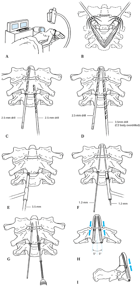 |
|
Figure 139.13. Direct anterior screw fixation technique. See text for details. [Part (A) redrawn from Grob D, Magerl F. Operative Stabilisirrung bei Frakturen von C1 and C2. Orthopade 1987:16; parts (B to I) redrawn from Muller ME, Allgower M, Schneider R, et al., eds. Manual of Internal Fixation Techniques Recommended by the AO-ASIF Group, ed 3. Berlin: Springer-Verlag, 1991:638, with permission.]
|
-
Positioning of the patient for anterior
dens osteosynthesis is critically important. Place the patient in the
supine position with the neck extended so that exposure of the inferior
edge of C-2 is possible. Rest the head on a Mayfield horseshoe head
support. If fracture reduction is lost (as may happen with posteriorly
displaced dens fractures), use less extension until provisional
fixation has been achieved. Biplanar image intensification monitoring
is essential (Fig. 139.13A). Perform an awake
fiberoptic intubation and document the neurologic status. Aid reduction
by placing a rolled towel under the neck for anterior displacement and
under the head for posterior displacement. -
Set up fluoroscopy so that satisfactory AP and lateral views can be obtained; simultaneous imaging is preferred.
-
When reduction is obtained, make a
standard anterior lateral approach through a transverse incision
centering the incision at the C5–C6 level (Fig. 139.13B) -
Make a retropharyngeal approach, as described by Smith-Robinson (see Chapter 138),
at the C5–C6 disc space level and carry the dissection up to the C2–C3
disc space. Make an incision in the anterior longitudinal ligament at
the level of the inferior portion of the C-2 body. A one- or two-screw
technique can then be used. -
Starting 3 mm to either side of the
midline and on the caudal edge of the body, medially insert a 1.5 mm
K-wire to ascertain trajectory and stabilize the fragment (Fig. 139.13C). Insert it across the fracture into the center
P.3685
of the odontoid. Two K-wires can be placed and a cannulated system
used, but inadvertent advancement of the wire is a complication;
preferably, one wire is removed and replaced at a time with a solid 2.5
mm drill bit advancing to the tip of the dens. -
Pass the drill bit over the guidewire and
advance it under fluoroscopic control. Take care—there have been
instances in which the guidewire has been advanced into the spinal cord. -
Because a lag effect is desired, either a
partially threaded screw can be used or one drill bit can be removed
and the near fragment overdrilled with a 3.5 mm drill bit (Fig. 139.13D). Tap the near cortex only (Fig. 139.13E, Fig. 139.13F and Fig. 139.13G). Be sure that all threads of this lag screw are across the fracture site. -
Final screw fixation should have the
screw slightly oblique toward the midline and optionally may perforate
the cortex of the tip of the dens (Fig. 139.13H and Fig. 139.13I).
Take care to begin the screw on the undersurface and not the anterior
surface of the C-2 body to achieve the proper trajectory (Fig. 139.13I).
biomechanical stability with two screws, and anatomic studies have
revealed that some odontoids are of inadequate size to accommodate two
screws (1,8,28,59). Postoperative immobilization in a Philadelphia collar for 6 weeks is generally sufficient.
that occurs through the pars interarticularis usually at its junction
with the posterior aspect of the vertebral body. Such fractures are
relatively uncommon and the mechanism of injury varies with the
fracture type. These usually occur in motor vehicle accidents in which
the head strikes the windshield or dashboard. The amount of
displacement and angular deformity is related to the amount of rebound
occurring from the associated acceleration and deceleration forces.
These fractures are generally not associated with significant
neurologic deficits because most of the injury patterns expand the
canal diameter. As with fractures of the atlas, if a deficit is
present, it may be related to a head injury or to some associated
injury. Diligently search for associated injuries that can occur in up
to 30% of patients with these fractures. Most of the concurrent
injuries occur in the adjacent three cervical levels (56).
to describe traumatic spondylolisthesis of the axis. The systems have
been based on either instability criteria (34), mechanism of injury (56), or anatomic or radiologic criteria (25,56,81).
The classification most commonly used now is based on four patterns,
each of which has both common radiographic and mechanistic
characteristics (Fig. 139.14) (56).
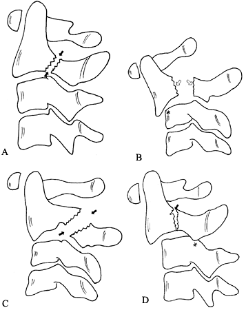 |
|
Figure 139.14. Traumatic spondylolisthesis of the axis can be characterized by the amount of translation and angulation at the fracture site. A: In a type I injury, the fracture line is either vertical or slightly off vertical (arrows). B: In a type II injury, the fracture line is relatively vertical with wide separation of the fragments (arrows).
These are characterized by more than 3 mm of translation and significant angulation as well. They frequently demonstrate a compression of the anterosuperior corner of the body of C-3 as a result of the flexion force that caused the anterior translation (star). In this case, avulsion of the anterosuperior corner of the body has occurred. C: Type IIA traumatic spondylolisthesis is different in its mechanism from type I and II injuries. Frequently, the fracture lines are more oblique (arrows) and are not located as close to the junction of the body and the pedicle as in the type I and II injuries. D: Type III traumatic spondylolisthesis of the axis combines fractures of the neural arch with facet injuries at C2–C3. The first type is a bilateral facet dislocation at C2–C3 (star) with a type I Hangman’s fracture at the base of the body–pedicle junction (arrowhead). (From Levine AM, Eismont FJ, Garfin SR, Zigler JE. Spine Trauma. Philadelphia: W. B. Saunders Co., 1998, with permission.) |
C-2, just posterior to the junction of the body and the pedicles. A
type I injury (Fig. 139.14A) is either a
nondisplaced fracture or minimally displaced, with less than 3 mm of
displacement and no angulation. It usually results from an axial load
with an associated hyperextension moment. The type IA, or atypical
hangman’s pattern (81), involves a fracture
between the junction of the pedicle and the body of C-2 in which, at
least on one side, a portion of the posterior wall breaks off and
remains attached to the pedicle. The significance of this pattern is
that, if there is any displacement, the cord can be compressed between
the ring of C-1 and the retained portion of the posterior wall. The
fracture line frequently traverses the foramen for the vertebral artery
and may result in intimal damage. A higher incidence of neurologic
deficits is associated with this pattern.
involves displacement and angulation of C-2 on C-3. A type II injury is
the result of a hyperextension axial load, which breaks the neural
arch, followed by a flexion injury, which results in significant
translation. The pattern of the fracture line is similar to that seen
with a type I injury.
has only minimal translation of C-2 over C-3 but has severe angulation.
The type IIA injury is characterized by minimal translation and
significant angulation with widening of the posterior aspect of the
disc space. With application of traction, these are the injuries that
will demonstrate significant widening of the disc. The mechanism is
different in that this type of injury occurs as a result of a flexion
distraction force. The fracture line, instead of being vertical at the
junction of the pedicle and the body is obliquely through pedicle.
Traction may produce distraction, leading to potential neurologic
injury.
is a pars fracture with an associated C2–C3 unilateral or bilateral
facet dislocation. The mechanism most probably is initial
flexion-distraction, which causes the dislocation, and then extension,
which causes the traumatic spondylolisthesis. Reversing the mechanism
would not permit the dislocation to occur, because the inferior facet
of C-2 would then be detached from the cervicocranium, which serves as
the lever for the dislocation. This pattern is associated with a higher
incidence of neurologic deficits.
spondylolisthesis can usually be made on a lateral cervical spine
roentgenogram. However, because most radiographs of this injury are
performed in the supine position, the true nature of the injury may be
obscured because any displacement may be reduced in the supine
position. Thus, to ensure that the injury is indeed a type I,
physician-supervised flexion-extension radiographs are necessary to
differentiate
it from a reduced type II. In order to undergo flexion-extension
radiographs, patients must be awake, alert, and neurologically intact,
and able to perform the flexion extensor maneuver themselves. Atypical
hangman’s fractures may require axial images from a CT scan to fully
appreciate the direction and extent of the fracture lines. Finally, in
type III injuries, a CT scan with reconstructions may be necessary to
characterize the facet component of the injury.
for 8 to 12 weeks. Late-onset degenerative arthritic changes can occur
in up to 30% of patients because the initial injury causes severe
impaction forces across the facet joint, which can be destructive to
the articular cartilage. Patients with type I injuries do not go on to
spontaneous ankyolsis across the C2–C3 disc, as is seen in type II
injuries. Treat type II injuries with significant amounts of
displacement or angulation initially by reduction using skeletal
traction in a slight amount of extension followed by a halo vest for 12
weeks. It is not uncommon for some reduction to be lost in the halo
vest, but this loss of reduction usually does not lead to any long-term
consequences. If the displacement is in the range of 6 to 7 mm,
alignment is maintained with a period of 4 to 6 weeks in halo traction,
followed by another 6 weeks in the halo vest. Alternatively, after
reduction in traction a direct osteosynthesis of the fracture can be
accomplished with a lag screw. Treat type IIA injuries with a halo vest
placed in compression and extension. This is achieved by placing the
halo vest on the patient in a routine fashion and then using the bolts
on the uprights to compress the ring down toward the vest.
immediate surgery. When this fracture pattern is identified, closed
reduction should not even be attempted because it is rarely achieved
and is potentially dangerous. Even if it is achieved, the remaining
instability present is enough to warrant arthrodesis. A preoperative
MRI is performed to evaluate the C2–C3 disc. The goal of surgical
treatment is to stabilize the C2–C3 facet joint. This can be
accomplished with a C2–C3 posterior plate with a C-2 pedicle screw and
a lateral mass screw at C-3.
-
Carry out a fiberoptic, awake intubation
and turn the patient prone on a Stryker frame. Check the patient’s
neurologic status and induce general anesthesia. Check lateral position
on fluoroscopy or plain radiographs. High-quality biplanar flouroscopy
is required to monitor the trajectory of the screws. -
Make a standard approach to the posterior
cervical spine from the occiput down to C3–C4 level and expose the
C2–C3 and C3–C4 facet joints. Use an elevator to dissect the medial
aspect of the C-2 pedicle. -
The facet joint at C1–C2 does not need to
be disrupted, but dissection from posterior to anterior toward the
facet will usually demonstrate the fracture of the pedicle. -
Then carry out the reduction of the
unilateral or bilateral facet dislocation at C2–C3. Place towel clips
on the spinous processes of C-2 and C-3. Spread the spinous processes
apart with a slight amount of flexion. This should unlock the jumped
facets. Apply a posterior translation force to the C-2 spinous process
as the towel clamps are brought together to achieve the final reduction. -
A bilateral subluxation is generally
easier to reduce than a unilateral subluxation because of the increased
ligamentous damage. Traction is not effective in this situation because
the break in the pars of C-2 prevents any force from being transmitted
to the C2–C3 joint level. Rarely, the C2–C3 facets need to be unlocked
manually. -
Place a Freer or small Cobb elevator into
the facet joint and gently elevate the C-2 facet until it becomes level
with the C-3 facet. Then apply a posterior translation force to the
towel clip on C-2 as the elevator is slowly removed to achieve
reduction. After reduction is obtained, the C2–C3 joint must be
stabilized. A standard interspinous process wiring or C2–C3 lateral
mass plating can be used; however, the pedicle fracture would then be
treated as a type II Hangman’s fracture with 12 weeks in a halo vest. -
An alternative method of fixation is to insert a C-2 pedicle screw to secure the pedicle fracture (Fig. 139.15A, Fig. 139.15B, Fig. 139.15C and Fig. 139.15D) (72).
If this technique is used, a partially threaded lag screw must be
placed so that the threads are beyond the fracture site to prevent any
distraction.![]() Figure 139.15. A:
Figure 139.15. A:
The surgical technique for osteosynthesis of a traumatic
spondylolisthesis of the axis. See the text for a description of the
technique. B: Orientation of the drills along the pedicle in an axial plane. Slight convergence of the screws is desirable. C:
Orientation across the fracture line from the posterior fracture to the
anterior fragment. A partially threaded screw, with usually about 15 mm
of thread and 20 mm of shank, is desirable. The proximal fragment can
be overdrilled and lagged to the anterior fragment. D: The final axial view. -
Before beginning screw insertion, take
care that the fracture is as reduced as possible and that a #4 Penfield
elevator can be placed along the medial border of the pedicle for
guidance. -
Verify the trajectory of the pedicle and
the location of the vertebral arteries on a preoperative CT scan.
Palpate the medial wall and gently retract the epidural soft tissue
medially. The fracture site and posterior body should be seen. Then
pass a drill, starting at the center of the facet and directed along
the pedicle into the body beyond the fracture site. -
Select a plate of the appropriate length and contour to fit the lateral masses of C-2 and C-3.
-
Place a partially threaded screw through
the plate across the pedicle fracture. The threads should be beyond the
fracture site, and no distraction of the pedicle fracture should be
observed. -
Place a standard C-3 lateral mass screw through the plate.
-
A rigid collar for 12 weeks is needed for postoperative immobilization.
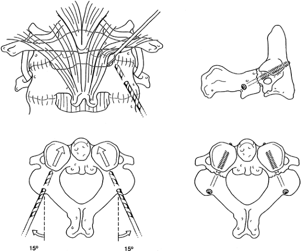
patterns only if there is an associated cervical fracture that requires
fixation, if conservative treatment fails, or if the use of a halo is
contraindicated. A C-2 pedicle screw (Fig. 139.15A, Fig. 139.15B, Fig. 139.15C and Fig. 139.15D)
can be used and offers immediate stability to the fracture. The
starting point for the screw is just medial to the C2–C3 facet joint on
the inferior edge of the lamina. Check the starting point on a lateral
fluoroscopic view. A preoperative CT scan is necessary to identify the
angle of the pedicle and the location of the vertebral artery. Use a
rigid collar for 8 weeks for postoperative immobilization. Anterior
arthrodesis for this injury has also been used with mixed results (40,41,87).
For type I fractures, union rates approach 98%. Recognition of other
associated injuries is important because these fractures can occur with
posterior arch fractures or odontoid fractures. The result of these
combined injuries follows that of the associated fracture. The most
common long-term problem of type I fractures is arthritic degeneration
of the C2–C3 facet joint, which occurs in approximately 10% of
injuries. For type IA fractures, the results are related to the
fracture pattern but generally are similar to type I fractures. For
type II fractures, displacement of 5 mm or more between the anterior
and posterior fragments yields a high incidence of nonunion, although
more than 70% go on to develop anterior fusions of the disc space.
Injuries with symptomatic nonunion and large gaps are generally not
amenable to C-2 pedicle screw fixation and
require
an anterior C2–C3 fusion. The results of type III fractures depend on
the severity of the commonly associated head injuries and neurologic
deficits. The overall success rate of fusion after reduction is
achieved is quite high.
fractures” have been described since the term was first used by
Schneider and Kahn in 1956 (76) the two most
common types are the flexion variant, which occurs in the lower
cervical spine, and the extension type, which occurs predominantly in
the upper cervical spine. The extension type of injury results from a
hyperextension and axial loading mechanism and may be observed in
combination with posterior arch fractures of the atlas and traumatic
spondylolisthesis of the axis. The injury can be easily diagnosed on a
lateral roentgenogram of the cervical spine. The triangular fragment
usually comprises approximately 50% of the height and 50% of the width
of the body. The vertebral body of C-2 remains in normal alignment with
the body of C-3, but the avulsed fragment is rotated anteriorly (Fig. 139.16).
This is in contradistinction to flexion teardrop injuries, in which the
fragment remains in relatively normal orientation to the bodies above
and below and the affected body is rotated posteriorly.
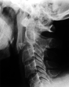 |
|
Figure 139.16. Extension teardrop fracture.
|
occur in combination with unstable contiguous injuries in the upper
cervical spine. If they occur alone or in combination with a stable
injury collar, immobilization is sufficient to achieve a satisfactory
result. If they occur in combination with an unstable injury, the
treatment of the second injury determines the overall treatment.
cervical spine fractures is diligent and thorough follow-up of the
patients after treatment. Progressive deformities and neurologic
deficits are more easily dealt with when recognized early. Union must
always be verified with maximum flexion-extension radiographs after
treatment.
requires the use of a halo vest, take care in its proper placement and
in follow-up. Complications include pin loosening, bone erosion, skull
perforation, pin track infections, and cerebrospinal fluid leaks. If a
circumferential collar is used, injury to the greater occipital nerve
must be recognized because loss of sensation in this area can lead to
occipital decubitus ulcers.
nonunion rates may be as high as 10%. Take care also with the passage
of sublaminar wires because neurologic injuries have been reported.
Mechanical testing has shown the transarticular screw to be more stable
than wiring techniques. The procedure is difficult, but the early
concerns of neurologic injury and the sequelae of perforation of one
vertebral artery are not as formidable as they were previously thought
to be. Clearly, if a vertebral artery injury does occur on one side, do
not attempt screw placement on the other side for any reason. Screw
malpositions have occurred in approximately 16% of cases, but
complications attributable to this problem are rare (less than 2%) and
include hypoglossal nerve irritation from excessive screw length,
instability from the screws not crossing the joint, and screw breakage.
and can cause spinal cord injury, cranial nerve injury, and loss of
fixation. Other technical problems include incomplete fracture
reduction with residual posterior angulation, incorrect screw entry
site, and posterior screw angulation. Because of these problems, only
experienced spine surgeons should use transarticular or anterior
odontoid screws.
added significant benefits to traditional wiring techniques.
Complications are associated with the placement of the Magerl screw, as
described previously. Leakage of CSF is not uncommon with the placement
of bicortical occipital screws, but no persistent leaks or significant
problems have been reported.
spectrum of not only fractures but also patterns of instability that
result from ligamentous disruption. The most critical features of the
treatment of these injuries are to appreciate the true nature of the
instability and the pertinent regional anatomy. Injuries of the upper
cervical spine have often been treated more aggressively than necessary
(e.g., halo vest for a posterior arch fracture or a Type I hangman’s
fracture). Surgery is often not necessary if appropriate use of
nonoperative modalities are employed.
have appeared that have been applicable to the upper cervical spine
injuries. The Magerl C1–C2 transarticular screw fixation has simplified
fixation for several different types of injuries. However, the
rationale for surgery has sometimes been the desire not to use a halo
as the immobilization device. Clearly, the risks and benefits have to
be discussed with the patient in an objective fashion before the final
treatment decision is made. For example, elderly patients have been
reported to have difficult times tolerating a halo as an immobilization
device, and physicians have resorted to operative procedures that also
have high rates of morbidity. For example, the use of an anterior dens
screw in the elderly patient with a Type II fracture without neurologic
deficit may have more morbidity than halo immobilization. More recent
studies suggest that less rigid immobilization may yield acceptable
patient outcomes without either the risks of surgery or a halo.
Accurate
assessment
of the true significance of the injury and its effect on spine
stability will ultimately yield the best patient outcomes.
scheme: *, classic article; #, review article; !, basic research
article; and +, clinical results/outcome study.
MB, Shepard MJ, Holford PR, et al. Administration of Methylprednisolone
for 24 or 48 Hours or Tirilizad Mesylate for 48 Hours in the Treatment
of Acute Spinal Cord Injuries: Results of the Third National Acute
Spinal Cord Injury Randomized Controlled Study—National Acute Spinal
Cord Injury Study. JAMA 1997;277:1597.
CA, Mamourian A, Sonntag VKH, et al. Magnetic Resonance Imaging of the
Transverse Atlantal Ligament for the Evaluation of Atlantoaxial
Instability. J Neurosurg 1991;75:221.
J, Hayek J, Zehnder R. CT-functional Diagnostics of the Rotatory
Instability of the Upper Cervical Spine: II. An Evaluation on Healthy
Adults and Patients with Suspected Instability. Spine 1987;12:726.
J, Panjabi M, Gerber M, et al. CT-functional Diagnostics of the
Rotatory Instability of the Upper Cervical Spine: I. An Experimental
Study on Cadavers. Spine 1987;12:197.
NA, Lu J, Bijani A, et al. An Anatomic Study of the Thickness of the
Occipital Bone: Implications for Occipitocervical Instrumentation. Spine 1996;21:1725.
VK, Winterbottom JM, Schulte KR, et al. Ligamentous Laxity Across
C0-C1-C2 Complex: Axial-torque Rotation Characteristics Until Failure. Spine 1990;15:990.
B, Magerl F. Primary Posterior Fusion of Cl-2 in Odontoid Fractures:
Indications Technique, and Results of Transarticular Screw Fixation. J Spinal Disord 1992;5:464.
B, Vernet O, Frei S, Magerl F: Atlantoaxial Mobility after Screw
Fixation of the Odontoid: A Computed Tomographic Study. J Spinal Disord 1991;4:203.
S, Joyce S, Seeger J. Asymmetry of the Odontoid-lateral Mass
Interspaces: A Radiographic Finding of Questionable Clinical
Significance. Ann Emerg Med 1986;15:1173.
F, Blondel M, Dhellemmes P, et al. Post-traumatic Atlanto-occipital
Dislocation Revealed by Sudden Cardiorespiratory Arrest. Lancet 1982;2:447.
F, Seemann PS. Stable Posterior Fusion of the Atlas and Axis by
Transarticular Screw Fixation. In: Kehr P, Weidner A, eds. Cervical Spine. Berlin: Springer-Verlag, 1986:322.
RC, Kahn EA. Chronic Neurological Sequelae of Acute Trauma to the Spine
and Spinal Cord, Part I: The Significance of the Acute Flexion or
“Teardrop” Fracture Dislocation of the Cervical Spine. J Bone Joint Surg [Am] 1956;28A:985.
PA, Young JWR, Mirvis S, et al. The Value of Retropharyngeal Soft
Tissue Measurements in Trauma of the Adult Cervical Spine. Skeletal Radiol 1987;30:1.