
VIII – THE SPINE > Trauma > CHAPTER 140 – FRACTURES AND
DISLOCATIONS OF THE CERVICAL SPINE FROM C-3 TO C-7
of death and disability, range in severity from simple soft-tissue
injuries to severe fractures or dislocations with paralysis or death.
Cervical spine injuries are often first detected in the emergency room
and must be carefully evaluated and managed to minimize adverse
sequelae. Early diagnosis, immobilization, preservation or restoration
of spinal cord function, and stabilization are the keys to successful
management of these injuries.
result from motor vehicle accidents, one third from falls, and the
remainder from athletic injuries, falling objects, or fired projectiles
(9). Most injuries occur to young and active
persons in adolescence or early adulthood. The second-largest group
comprises adults in their sixth or seventh decades. In this age group,
preexisting spondylosis or stenosis may predispose these patients to
severe injuries despite a relatively small amount of force being
imparted to the cervical spine.
progress in emergency care, medical and surgical intervention, and
rehabilitation of the patient who has sustained a spine and/or spinal
cord injury. A team approach is important to obtain optimal results.
The therapeutic goals are to preserve life, maintain or restore
neurologic function, provide stabilization of the cervical spine, and
allow optimal rehabilitation. These goals are attainable if appropriate
care is provided.
injury begins at the scene of the accident. Carefully move the patient
to safety and then immobilize her on a long backboard and apply a rigid
cervical collar. Stabilize the head by placing sandbags along each side
or use tape to secure the forehead to the board. Paramedics or other
emergency management team members often perform the initial assessment
and resuscitation.
resuscitation. Follow advanced trauma life support (ATLS) guidelines.
If an airway needs to be secured, take care to prevent further cervical
injury by utilizing fiberoptic nasotracheal intubation whenever
possible. This technique minimizes movement of the injured cervical
spine. Intravenous access is mandatory for fluid resuscitation in cases
of neurogenic shock.
witnesses to determine the mechanism of injury and the circumstances
surrounding the accident. A history of loss of consciousness is
important, as the patient may not be able to accurately recall the
events as they occurred. In addition, there is a high correlation
between head trauma and cervical spine injuries. Make note of the
initial neurologic assessment, with attention to any paralysis.
exam. The observation of craniofacial trauma can be important in the
assessment of the mechanism of injury. If the patient is conscious,
gently palpate the anterior and posterior cervical spine to determine
the site of pain or swelling. Palpate the posterior elements in the
midline posteriorly, noting any increase in the interspinous distance.
Palpate the anterior vertebral bodies in the interval between the
sternocleidomastoid and the trachea.
general state of consciousness as well as respiratory status. The C-3
to C-5 levels innervate the diaphragm. Cord injury above the C-5 level
may lead to respiratory failure. If the patient is conscious, perform
motor, sensory, and reflex examination of the upper and lower
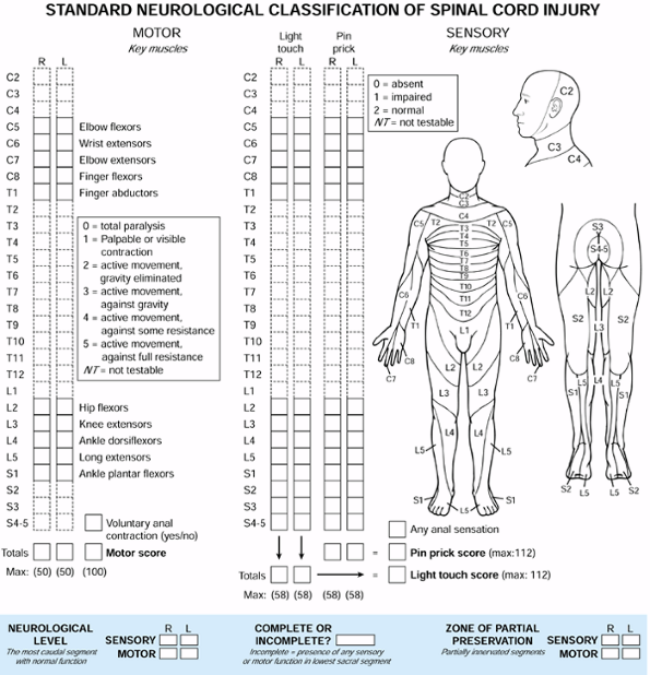
extremities. The American Spine Injury Association (ASIA) spinal cord
injury assessment form (Fig. 140.1) provides an
excellent checklist to ensure completeness. Use rectal tone and
perianal sensation to assess for the presence of sacral sparing.
Document the absence or presence of the bulbocavernosis reflex for the
determination of spinal shock.
 |
|
Figure 140.1.
American Spine Injury Association (ASIA) spinal cord injury assessment form. (Redrawn with permission from the American Spine Injury Association. Standard Neurological Classification of Spinal Cord Injury, revised. Chicago: American Spine Injury Association, 1992.) |
Delay in diagnosis ranged from 1 day to 1 year. The common causes for
lack of recognition were concomitant closed head injuries, multiple
traumatic injuries, alcohol intoxication, and initial misdiagnosis such
as cerebrovascular accidents. An alteration in consciousness
contributed to the lack of proper evaluation and failure to take
appropriate radiographs. Patients with these injuries often do not
complain of pain, and facial and neck lacerations may detract from the
evaluation of the cervical spine. Nevertheless, the physician always
must suspect a cervical spine injury any time there is associated head
trauma (7,18).
lateral view of the cervical spine, anteroposterior (AP) view of the
chest, and AP view of the pelvis. Approximately 80% of cervical spine
fractures can be diagnosed on the initial lateral view if it is
adequately done (49,53).
Once the patient is stabilized, complete the remaining views of the
cervical spine trauma series. This includes the AP, open-mouth
odontoid, and bilateral obliques or pillar views. The lateral view must
extend to the C7–T1 level to be considered complete (7,36).
A swimmer’s view may be required to visualize the C7–T1 level in
patients with short necks. If visualization still remains questionable,
perform a computed tomography (CT) scan (59).
alignment or fractures. The presence of retropharyngeal soft-tissue
swelling is important and may indicate adjacent fractures or
ligamentous injuries (20). Loss of facet
parallelism, facet overlap, or widening of the distance between
adjacent vertebrae may also indicate ligamentous injury. If
abnormalities are noted, a CT scan is helpful in defining the
compromised structures and the presence of bone or disc fragments
within the spinal canal. Ligamentous injuries are best visualized by
magnetic resonance imaging (MRI) performed within the first 72 hours (23,45).
Little inherent stability is achieved from the interrelationships of
the osseous structures, and therefore the integrity of the supporting
ligaments is very important (34,40). The anterior and posterior longitudinal ligaments span the length of this region and are firmly adherent to the annulus
fibrosis at each level. These ligaments, along with the annulus, are
the primary stabilizers of the anterior column. Posteriorly, the
interspinous, supraspinous, and facet joint capsules comprise the
primary ligamentous stabilizers. The ligamentum flavum becomes
important at the extremes of motion (56).
longitudinal ligament and the annulus fibrosis, act as a tension band
during extension. Similarly, the posterior longitudinal ligament,
supraspinous and interspinous ligaments, and facet capsules act as a
tension band in flexion (57). Flexion
compresses the anterior column and tensions the posterior column,
whereas extension tensions the anterior column and compresses the
posterior column. Thus, the anterior and posterior columns are
reciprocally affected by sagittal plane motion (27).
the cervical spine is achieved through the occipital cervical
articulation. The remainder occurs through the lower cervical
vertebrae, ranging from 8° to 17° at each motion segment. Rotation is
equally shared between the atlantoaxial joint and the lower cervical
vertebrae. Lateral bending in the subaxial region ranges from 4° to 11°
at each segment (58).
In a retrospective review of 165 cases of lower cervical spine injury,
they developed a mechanistic system of classifying closed indirect
fractures and dislocations.
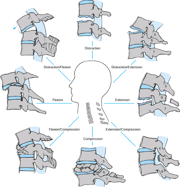
according to the dominant force vector leading to failure and the
position of the cervical spine at the time of injury (Fig. 140.2).
The groups include compressive flexion, vertical compression,
distractive flexion, compressive extension, distractive extension, and
lateral flexion. The three most common groups are compressive flexion,
distractive flexion, and compressive extension. The least common are
distractive extension and lateral flexion, with vertical compression
falling between. Compressive indicates that compression accounts for the initial structural failure in a motion segment, whereas distractive indicates that tension is the dominant force. The use of flexion or extension denotes the position of the cervical spine at the time of injury (3).
 |
|
Figure 140.2.
Mechanistic classification of lower cervical spine injury. (Modified from Allen BL, Ferguson RL, Lehmann TR, O’Brien RP. A Mechanistic Classification of Closed, Indirect Fractures and Dislocations of the Lower Cervical Spine. Spine 1982;7:1, with permission.) |
Although the degree of neurologic injury cannot be correlated with the
staging, the risk of injury is certainly greater in the advanced stages.
(CF) group. The force vector is directed anteriorly and inferiorly. In
CFS1 injuries, mild blunting of the anterior-superior vertebral body is
noted, caused by impression of the more superior vertebrae. In CFS2,
the anterior vertebral body loses additional height and becomes wedged,
but still without disruption of the posterior ligamentous structures.
In CFS3, a fracture line passes obliquely from the anterior vertebral
surface to the inferior endplate without displacement. CSF4 injuries
have subluxation and displacement of the posterior vertebral wall into
the spinal canal, but not exceeding 3 mm. CFS5 injuries involve severe
displacement of the body fragment into the canal, as well as increased
interspinous distance, facet subluxation, and posterior longitudinal
ligament disruption (3).
flexion (DF) group. The force vector is directed anteriorly, away from
the trunk, with the neck flexed. In DFS1 injuries, posterior
ligamentous disruption with facet subluxation and increased
interspinous distance is noted. DFS2 represents a unilateral facet
dislocation and DFS3 a bilateral facet dislocation. In DFS4, the
superior vertebral body is displaced anteriorly, the full width of the
body, creating a “floating” vertebra (3).
potentially unstable, although DFS1 injuries can commonly be treated
nonoperatively. DFS2–4 commonly require operative intervention to
prevent late instability (5,7,22,44).
(CE) group, although the distinction between the latter stages remains
unclear. Unilateral vertebral arch fracture with or without
displacement is found in CES1 injuries. Bilateral involvement
distinguishes CES2. In CES3–5, comminution of the lamina and lateral
masses occurs with vertebral or disc space separation. In CES5,
complete anterior displacement of the superior vertebral body is noted (3).
nonoperatively. However, the higher stages, especially CES5, usually
require operative stabilization.
(VC) group, in which the force vector is axial. In VCS1 injuries, a
fracture occurs through either the superior or the inferior endplate.
VCS2 involves a fracture through both endplates, but with minimal
displacement. In VCS3, further compression causes the fracture
fragments to displace peripherally, possibly through a tear of the
posterior longitudinal ligament (3).
healing when treated nonoperatively. However, VC3 injuries with canal
compromise require operative decompression and stabilization (1,2).
(DE) group, in which the force vector is directed posteriorly, away
from the trunk, with the head in extension. DES1 injuries involve
either a transverse fracture through the vertebral body or disruption
of the anterior ligamentous complex. DES2 consists of failure of the
posterior ligamentous structures with displacement of the superior
vertebral body into the canal (3).
heal nonoperatively without deformity. DES2 injuries, however, often
require operative intervention.
group, in which the force vector is directed laterally. In LFS1
injuries, an ipsilateral vertebral body fracture and neural
arch fracture are noted, without displacement. LFS2 progresses to displacement (3). Treatment depends on the extent of the injury, but most LFS1 injuries may be treated nonoperatively.
defined clinical instability as the “loss of the ability of the spine
under physiologic loads to maintain relationships between vertebrae in
such a way that there is neither initial nor subsequent damage to the
spinal cord or nerve roots, and in addition, there is neither
development of incapacitating deformity nor severe pain.” In this
definition, physiologic loads are those incurred during normal daily
activity. Incapacitating deformity is defined as gross deformity that
the patient finds intolerable. Severe pain is that which cannot be
controlled by nonnarcotic medications.
devised a checklist, incorporating both clinical and radiographic
parameters. Radiographic parameters for ligamentous instability were
established through biomechanical studies. Using fresh cadaveric
specimens, serial sectioning of the posterior and anterior ligamentous
structures was performed. Abnormal motion of the adjacent vertebrae was
then measured. In an otherwise intact spine, instability was defined as
translatory displacement of two adjacent vertebrae greater than 3.5 mm,
or angulation greater than 11° compared with adjacent motion segments.
Based on these and other results, a comprehensive checklist was
developed for assessing traumatic instability.
radiographic findings are assigned point values. Assign two points each
for anterior elements destroyed or unable to function, posterior
elements destroyed or unable to function, relative sagittal plane
translation greater than 3.5 mm, relative sagittal plane rotation
greater than 11°, positive stretch test, or spinal cord damage. Assign
one point each for nerve root damage, abnormal disc space narrowing, or
dangerous loading anticipated. If the total point value is equal to or
greater than five, assume instability of the motion segment (54).
determination of spinal instability, each case should be assessed
individually; the importance of certain criteria may vary depending on
the specific situation. Of prime importance is spinal cord integrity.
When spinal cord injury is caused by extruded bone fragments, or
deformity resulting from ligamentous disruption, assume instability.
Evidence of isolated nerve root compromise is a weaker indicator of
instability.
evaluating the integrity of the ligamentous structures of the middle
and lower cervical spine. This test is performed as follows:
-
Apply traction through the use of secure skeletal fixation or a head halter device.
-
To reduce frictional forces, place a roller under the patient’s head.
-
Place the radiographic plate 14 inches from the patient’s spine and the tube 72 inches from the plate.
-
Take an initial radiograph to ensure no occiput to C-1 to C-2 subluxation.
-
Add a 10-pound weight and obtain a lateral radiograph.
-
Repeat this process, increasing the
traction by 10-pound increments until reaching one third of the body
weight, or 65 pounds, whichever is less. -
After each additional weight application,
check the patient for any change in neurologic status. If there is a
change in status, stop the test. The test is then considered to be
positive.
the anterior or posterior elements. An abnormal test is indicated by
differences either greater than 1.7 mm of interspace separation or 7.5°
of change in the angle between vertebrae (35).
An interval of at least 5 minutes should be allowed between incremental
weight applications to allow for creep of the viscoelastic structures.
The test is contraindicated in a spine with obvious clinical or
radiographic instability.
in an orderly fashion to minimize morbidity and mortality. At the time
of initial evaluation and resuscitation, immobilize the injured spine
as medical stabilization is implemented. Assess spinal alignment and
correct it if necessary. Perform operative decompression if indicated
and consider the long-term stability of the injured spine. If the
injured segment or multiple segments are unstable, operative
stabilization is necessary.
radiographs, realignment is indicated to relieve any pressure on the
neural elements, limiting ischemia and edema formation. Exactly what
constitutes significant malalignment is debatable; however, sagittal
translation greater than 3.5 mm or angulation greater than 11° would
seem reasonable. In addition, realignment or traction would also be
indicated in injuries in which extruded bone or disc fragments were
contributing to spinal cord or nerve root compromise, even though no
significant angulation or translation were present. Reduction can
usually be established by skeletal traction with tongs in the skull (16).
-
After the tongs are applied in a sterile fashion, apply an initial weight of 10 pounds of traction with appropriate analgesia.
-
Perform a detailed neurologic examination and obtain a lateral radiograph.
-
Perform careful evaluation of the occiput to C-1 to C-2 levels to ensure no concomitant injury to this region.
-
If reduction is not achieved, add weight in 5-pound increments and repeat the process each time.
-
Once reduction is obtained, reduce the
weight to 15–20 pounds and obtain a repeat radiograph to confirm
maintenance of reduction. -
Continue traction until a definitive treatment plan is chosen.
body weight or 65 pounds (whichever is less) is unable to achieve
adequate reduction, operative intervention is usually required. In
cases of facet dislocation, closed manipulative reduction may be an
option when traction alone fails to reduce the dislocation. This should
be performed only by surgeons experienced in these techniques to
minimize the risk of, or exaggeration of, neurologic injury.
substantial disruption of the anterior and posterior ligamentous
structures and clinical instability. Patients who are undergoing
realignment in traction must be constantly monitored and examined to
prevent iatrogenic injury to the neural elements resulting from
excessive stretching across injured segments. Traction weights should
begin at 5 pounds and progress cautiously in order to ensure that
overdistraction does not occur.
and in whom the stability of the spine has not been jeopardized, a
course of bracing in a rigid orthosis for 6–12 weeks may be
appropriate. Injuries included in this category are mild compression
fractures of the anterior elements and isolated fractures of the
posterior elements or lateral masses. Mild vertical compression
fractures may require halo immobilization. Follow-up radiographs must
be obtained at regular intervals to assess healing. If instability is
noted on follow-up radiographs, operative intervention is required.
cervical spine injuries is indicated in all cases for which
decompression is necessary to restore or preserve spinal cord function,
and if stabilization is required to prevent further cord or root injury
(8,42). Schneider et al. (43)
formulated their criteria for urgent operative intervention in patients
who had sustained cervical spinal cord injuries. The criteria they
deemed important included documented progression of neurologic signs
and complete block of the subarachnoid space on myelography. Cooper and
Ransohoff (15) included any myelographic
evidence of spinal cord compression by hematoma or by bone or disc
elements after alignment had been optimized.
patient with a complete neurologic deficit with loss of motor function
distal to the injured segment. Such a patient is unlikely to achieve
functional recovery, and operative intervention to stabilize the spinal
column may be delayed until he is medically stable. However, urgent
decompression of compromised nerve roots may be required in some such
patients to preserve an additional neurologic level. Urgent
stabilization of the spinal column may also be necessary to facilitate
the treatment of other system injuries.
the procedure depends on the nature of the injury and the goals of the
surgeon. In general, approach the fracture from the site of major
instability (47,51,55).
If the injury involves the anterior longitudinal ligament, vertebral
body, or disc, an anterior approach is most appropriate. If there is
posterior ligamentous involvement or posterior element fractures, a
posterior approach is preferred. Sometimes, combined anterior and
posterior approaches are required (17). Perform a stabilization procedure at the site of decompression.
posterior cervical wires or cables and lateral mass plates. In recent
years, multistrand stainless steel or titanium cables have replaced
traditional stainless steel wires. Multiple studies have shown that
cables are stronger, more flexible, and more fatigue resistant than
wires (19,28,46).
However, the cables are also more expensive. In addition, the added
bulk of the crimping device may detract from its use in certain
situations. Most posterior wiring techniques require intact posterior
arches and spinous processes across the levels to be fused. To provide
sufficient
spinal stability, the anterior column should be capable of weight bearing, and excessive rotational forces must be avoided (14,24). When these conditions are not present, lateral mass plates are preferred (31).
However, it should be kept in mind that a real risk to the spinal cord,
nerve roots, and vertebral arteries exists with lateral mass plating.
Posterior cervical wiring techniques have fewer risks and years of
proven success (11,52).
In his description, a wire was passed through and around the base of
adjacent spinous processes. Corticocancellous bone grafts were placed
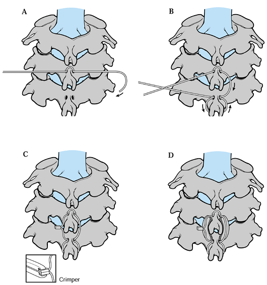
under the wires, across the interlaminar space to facilitate fusion. Figure 140.3 diagrams the use of a flexible multistrand cable in a procedure similar to that presented by Rogers (see Rogers’s technique in the next section).
 |
|
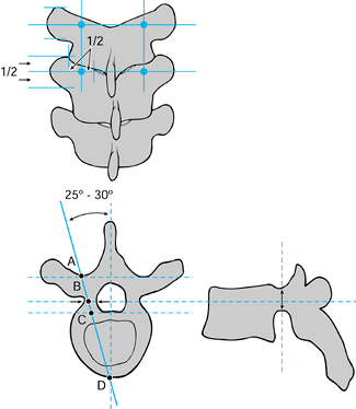
Figure 140.3. Interspinous technique using flexible multiple cables. A:
Pass cable 1, near to far, through the C-4 drill hole. Loop it around cephalad edge of the C-4 spinous process, and then pass through the hole again, near to far. B: Then pass cable 1, far to near, through the C-5 hole, loop it around the caudal edge of the C-5 spinous process, and then pass it through the hole again, far to near. C: Apply crimp to achieve single interspinous wiring. D: The bone is then in place under the parallel interspinous portions of the cable. |
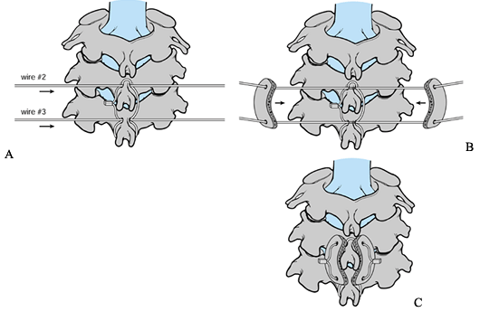
Rogers’s, in which an additional two wires are used to secure the bone
graft to the lamina and spinous processes (30).
Bohlman’s modification results in increased flexural and torsional
stiffness that is superior to Rogers’s wiring technique and to
sublaminar wiring techniques (Fig. 140.4, Fig. 140.5 and Fig. 140.6).
 |
|
Figure 140.4. Interspinous technique using two additional wires. A: Pass the upper and lower wires through the drill holes in the C-4 and C-5. B: Cinch the bone grafts simultaneously onto C-4 and C-5. C: The bone grafts are then in position.
|
 |
|
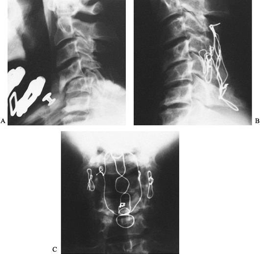
Figure 140.5. A:
Lateral radiograph of a 40-year-old lumberjack struck on the back of his neck by a falling tree. There is anterior subluxation of C-4 on C-5. The anterior subluxation was not adequately held despite the application of a halo vest. B: Lateral radiograph after posterior reduction and triple-wire stabilization from C-3 to C-6. Notice that there are two wires linking the facet joints at C4–C5 and a midline tethering wire bridging the base of the spinous processes from C-3 to C-6. There are no sublaminar wires. C: AP radiograph showing the lateral interfacet wires and the midline tethering wires. The patient at 1-year follow up was neurologically completely intact and his spine was completely fused. He returned to work as a lumberjack doing heavy manual labor. |
 |
|
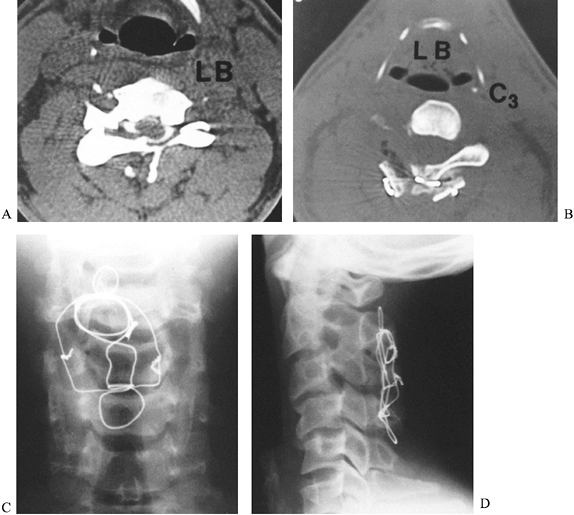
Figure 140.6. A:
Axial CT image of a 25-year-old man who sustained a diving injury. The patient has a fracture dislocation of the left C-3 facet joint. The inner aspect of the lamina is seen compressing the posterior aspect of the spinal cord. He had numbness on the left side of his neck in the C-3 nerve distribution. In addition, he was hyperreflexic throughout, secondary to a myelopathic lesion. B: The patient underwent a posterior decompression and triple-wire stabilization from C-2 to C-4. This axial postoperative CT image shows the posterior wiring and bone graft that stabilized the spine. Notice the adequacy of the decompression of the spinal canal. C: AP radiograph of the triple-wire stabilization technique from C-2 to C-4. The lateral wires hold two corticocancellous bone grafts in compression against the posterior aspects of the lamina at C-2 and C-4. D: Postoperative lateral radiograph shows a solid fusion from C-2 to C-4 with good spinal alignment aside from the patient’s original 15% subluxation at C3–C4. The patient was neurologically completely intact, and his spine was stable at long-term follow-up. |
injury or decompression, Rogers’s and Bohlman’s techniques cannot be
used. An alternative to lateral mass plating is facet wiring, reported
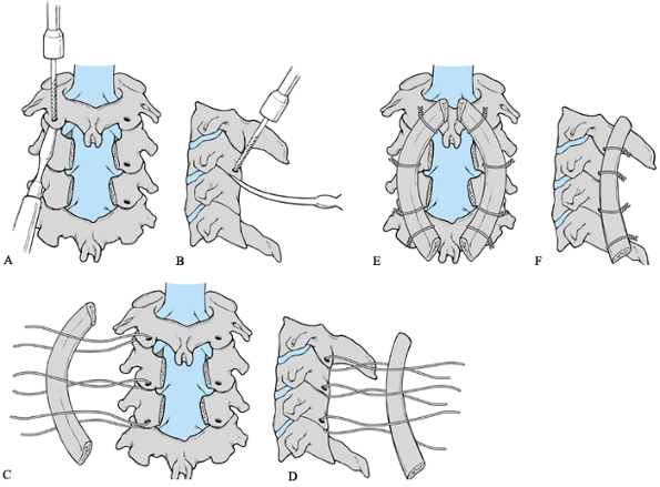
by Robinson and Southwick in 1960 (38), and modified by Callahan in 1977 (Fig. 140.7) (11).
In this technique, the articular processes are denuded and wires are
passed through the inferior articular processes, which are then secured
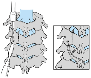
to overlying bone graft. In the case of rotational instability, or when
there is a one-level lamina fracture, oblique facet wiring is an option
(Fig. 140.8) (10,21).
Wires are placed through the inferior facet as described later in the
facet wiring technique, but then secured to the next inferior spinous
process instead of overlying bone graft. Bilateral wiring from the
facets to the inferior spinous process is recommended.
 |
|
Figure 140.7. Facet-wiring technique. A and B: Holes are drilled at a 90° angle to the articular surface. A: AP view. B: Lateral view. C and D: A curved rib graft or a portion of the iliac crest is used to create a cervical lordosis. C: AP view. D: Lateral view. E and F: Free wires emanate from the caudal end of the spinous process and are securely fixated to the graft or rod. E: AP view. F: Lateral view.
|
 |
|
Figure 140.8.
Oblique facet wiring. A small drill is used to create a hole in the inferior articular process at a 90° angle to the articular surface. (Inset) Wires in place in the drill holes after being tightened and securely fixated. |
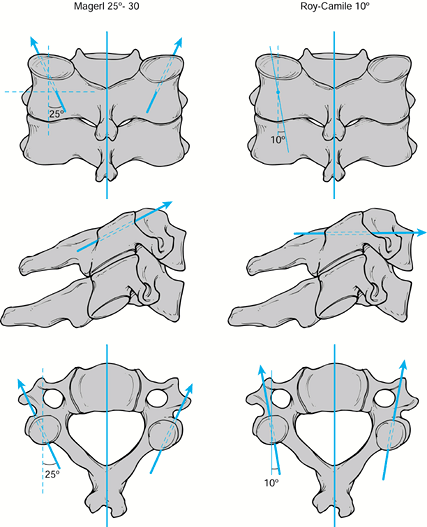
posterior wiring techniques. Plates are fixed to the lateral masses by
screws placed at each level. Two methods of screw placement are
commonly used, the original technique described by Roy-Camille et al. (41) and the Magerl technique (29). Of the two techniques, Magerl’s is more commonly used because it provides a stronger and stiffer construct (Fig. 140.9) (32).
 |
|
Figure 140.9. Screw direction for the Magerl and Roy-Camille techniques.
|
traction throughout the case. Fiberoptic intubation is preferred to
minimize any movement of the unstable spine.
-
Following intubation, turn the patient
prone on a spine-turning frame. If possible, keep her awake until after
she is prone to monitor for any neurologic changes. Intraoperative
neurologic monitoring [e.g., for somatosensory evoked potential
(SSEP)], is helpful in identifying changes. -
Hold her face in a Mayfield head holder or other similar device.
-
Tuck her arms at her sides. With 3-inch
tape, secure her shoulders down to the foot of the bed with a gentle
longitudinal pull. This permits radiographic visualization of the lower
cervical spine. -
Obtain a preoperative radiograph in the prone position to verify spinal alignment.
-
Shave and prepare the neck from the
occiput to the midscapular region as well as the posterior iliac crest
for bone graft harvesting. -
Make a midline incision overlying the injured area and use the cautery knife to expose the tips of the spinous processes.
-
Dissect the subperiosteal soft tissues off the posterior elements to the lateral border of the articular masses.
-
Take care to avoid undue pressure over the compromised levels.
-
If the injured levels are difficult to identify intraoperatively, use radiographic localization.
-
Decompress the areas dictated by the preoperative studies, and perform one of the following fusion techniques.
-
After the stabilization procedure, obtain a radiograph to assess the reduction and to confirm the levels of fusion.
-
Close the wound in layers over a drain.
-
Continue prophylactic antibiotics for 24–48 hours.
-
Using a burr, make a hole in the
midportion of the base of each spinous process to be included in the
fusion. Avoid penetration of the laminae. -
Place a pointed towel clip through each hole to confirm adequate room for passage of the cable.
-
Pass the cable through the hole in the
most superior spinous process, and then wrap the cable around the
spinous process and reenter the hole from the same direction (Fig. 140.3). This creates a tethering loop around the spinous process, decreasing the chance of the cable cutting out of the bone. -
From the opposite direction, pass the
wire through the next spinous process to be included in the fusion, and
follow a similar technique. -
Both ends of the cable should end on the same side of the patient. Tighten the construct and secure with the crimping device.
-
Cut the cables flush with the crimp.
-
Measure the length of the graft needed with a malleable probe.
-
Harvest the corticocancellous graft from
the posterior iliac crest. An oscillating saw minimizes the risk of
microfractures in the graft. A piece that is the proper length and
width can be split into two pieces for each side of the fusion. -
Using a saw, split the graft longitudinally.
-
Before the graft is placed, remove all
the soft tissue covering the lamina and roughen the bone surfaces with
a burr to allow fusion to occur. -
Place the bone grafts underneath the cables, spanning the interlaminar space.
-
Place the first cable as described for Rogers’s technique.
-
Place the remaining two cables through
and around the most superior and inferior spinous processes to be
included in the fusion (Fig. 140.4 and Fig. 140.6). -
Burr holes toward each end of the previously harvested corticocancellous grafts.
-
In addition to roughening the surface of
the lamina, include the portion of the spinous process that will be in
contact with the graft as well. -
Place the cables through each end of the
graft and tighten them simultaneously, orienting the graft into its
most stable configuration. -
Crimp and cut the cables as in Rogers’s technique.
-
Pack extra bone along the sides of the grafts if needed.
-
Identify each articular facet to be included in the fusion.
-
Using a small, thin elevator, pry open the joint and rotate the elevator to maintain exposure of the joint surfaces (Fig. 140.7).
-
Denude the surfaces with a burr to facilitate fusion.
-
Drill a 3 mm hole at 45° off the horizontal through the inferior facet.
-
Pass a cable through this hole from a
posterior to anterior direction and grasp it from within the joint to
deliver it into the field. -
Repeat this process bilaterally at each level to be included in the fusion.
-
Use a burr to gently roughen the posterior surfaces of the lateral masses to be fused.
-
Secure the corticocancellous grafts to the lateral masses by tightening and crimping the cables.
-
Holes may be drilled though the grafts for more secure fixation.
-
Drill a hole through the inferior articular facet as described for facet wiring.
-
Burr an additional hole through the base of the next inferior spinous process (Fig. 140.8).
-
After passing the cable through the facet, pass it through and around the spinous process.
-
Tighten and secure as previously noted for other techniques.
-
Apply bone graft wherever possible.
-
Using the Magerl technique, identify the
four borders of each lateral mass to be included in the fusion. The
medial border is the valley at the junction of the lamina and the
facet. The lateral border is the far edge of the articular mass. The
superior and inferior borders are the respective facet joints. The
starting point is 1–3 mm medial to the center of the four borders of
the lateral mass (Fig. 140.9). -
Direct the drill bit 30° to 40°
superiorly, parallel to the facet joints, and 25° to 30° laterally. Use
bicortical purchase and breach the far cortex by the “loss of
resistance” technique with an oscillating drill. A depth gauge
accurately assesses the length of screw needed, which is generally
16–22 mm. The vertebral artery is located directly anterior to the
valley at the junction of the lamina and articular mass. Avoid this
artery by aiming the screws laterally. Avoid the nerve roots by keeping
the screws within the articular masses, aiming parallel to the
articular surfaces. -
Place the most superior screw in the construct, as described for the Magerl oblique facet wiring technique.
-
Drill the pilot hole with a 2 mm drill bit, aiming parallel to the articular surfaces and approximately 25° laterally.
-
Place the appropriate-length plate over the lateral masses to be included in the fusion.
-
Use the depth gauge to measure the length of the hole.
-
Insert the appropriate-length screw and tighten moderately.
-
Screw placement for the remaining
articular masses will be somewhat dictated by the plate hole
configuration. Place the remaining screws in a fashion similar to the
first one. -
Tighten all screws securely at the end of the procedure.
-
Denude the joints with a burr and apply local bone graft prior to plate placement.
cervicothoracic junction, extension of the posterior plating construct
to the upper thoracic vertebrae can be achieved. Fixation to the
thoracic spine may be through the use of pedicle screws or hooks,
depending on which plate or plate–rod construct is utilized. If pedicle
screws are desired, the placement technique must be changed from that
used for lateral mass screws (Fig. 140.10). Aim
the upper thoracic pedicle screws 25° to 30° medially, with the
starting point at the intersection of the midportion of the facet joint
and the midportion of the transverse process. Thoracic pedicle screw
placement is demanding and should be performed only by surgeons
experienced in these techniques.
 |
|
Figure 140.10. Thoracic pedicle screw placement.
|
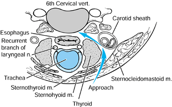
Currently, the Robinson anterolateral approach between the carotid
sheath and the esophagus is optimally suited for access to levels C-3
to C-7. With exacting technique, it is possible to reach as superior as
the second cervical vertebra and as inferior as the second thoracic
vertebra. In fracture management, this approach is suited for
decompression of herniated disc material and of retropulsed fragments
from compressed vertebral bodies.
after decompression for traumatic injuries. Without instrumentation,
loss of reduction and graft displacement occur in up to 64% of anterior
decompression and strut graft reconstructions (2,6,26,48).
The first-generation anterior cervical plates required bicortical
purchase of the screws because there was no mechanism for locking the
plate–screw interface. This problem was solved with the
second-generation plates, which do not require bicortical purchase of
the screws and have a rigid plate–screw interface. Morscher et al. (33)
established the concept of the cervical locking plate—that is, a rigid
plate–screw interface. A variety of second-generation systems are
available today.
-
If the patient has previously been placed in traction, maintain traction for the remainder of the case.
-
Use fiberoptic equipment to insert a
nasotracheal or endotracheal tube, avoiding manipulation of the
unstable cervical spine during intubation. -
Position the patient carefully on the
operative table. Tuck his arms at his sides and tape his shoulders down
to the foot of the bed to permit radiographic visualization of the
lower cervical levels. -
Obtain a preoperative lateral radiograph to check alignment.
-
Prepare the skin aseptically from the
chin to the nipple line bilaterally, as well as the anterior iliac
crest for graft harvesting. -
Identify the carotid tubercle of the C-6
vertebra (Chassaignac’s tubercle) for orientation purposes. If this is
not palpable, the hyoid bone overlies C-3, thyroid cartilage is at C-4
to C-5, and cricoid cartilage localizes C-6. Use these landmarks to
adjust the position of the skin incision in relation to the injured
level. -
Make a transverse incision on the left or
right side of the neck, whichever is preferred, extending from the
midline to just past the anterior border of the sternocleidomastoid.
Alternatively, use an oblique incision along the anterior border of the
sternocleidomastoid to approach several levels (Fig. 140.11, Fig. 140.12).
The rationale for approaching on the left side of midline is that the
recurrent laryngeal nerve ascends in the neck on the left side between
the trachea and the esophagus, having branched off from its parent
nerve, the vagus, at the
P.3708
level
of the arch of the aorta. On the other hand, the right recurrent
laryngeal nerve travels alongside the trachea in the neck after passing
beneath the right subclavian artery. In the lower part of the neck, the
right recurrent laryngeal nerve is vulnerable to injury as it passes
from the subclavian artery to the tracheoesophageal groove. Its course
in the groove is also more variable on the right than on the left.
Therefore, there is theoretically less risk to the recurrent laryngeal
nerve by using the left-sided approach. However, the approach on the
left has the possibility of injuring the thoracic duct, which enters
the jugular vein–subclavian vein junction at the base of the neck on
the left.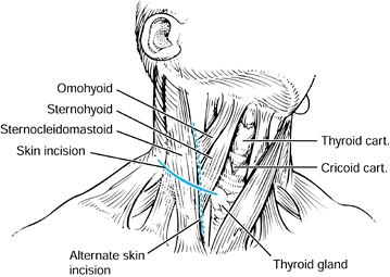 Figure 140.11. Longitudinal and transverse incisions allow the necessary exposure to the anterior cervical spine.
![]() Figure 140.12.
Figure 140.12.
The anterior spine can be visualized with dissection in the plane
between the thyroid and the carotid sheath, which should be gently
retracted laterally. -
Identify and elevate the platysma, incising it in line with the incision using Metzenbaum scissors.
-
Next, incise the superficial layer of the
deep cervical fascia along the anterior border of the
sternocleidomastoid. Proper exposure is necessary to facilitate
mobilization of the underlying structures. The omohyoid muscle
traverses the field and can be retracted or divided as necessary. -
Palpate the arterial pulse to identify the carotid artery within its investing sheath.
-
The middle layer of the deep cervical
fascia is the next important layer to be divided. Divide it
longitudinally, medial to the carotid sheath. Identify the carotid
artery (by using your fingers), and protect it as this layer of fascia
is divided. Retract the artery laterally, along with the internal
jugular vein, vagus nerve, and phrenic nerve. -
Carry blunt dissection through the loose areolar tissue to the anterior cervical spine.
-
Identify the esophagus medially, and
retract it with a blunt Richardson retractor. Use a thyroid retractor
to retract the carotid sheath and sternocleidomastoid laterally. -
Identify and protect the recurrent
laryngeal nerve, which descends along the carotid sheath and ascends
between the trachea and esophagus. This structure can be injured with
sharp retractors or prolonged pressure. -
The midline of the anterior cervical
spine can be palpated, as well as the anterior carotid tubercle at C-6.
This landmark can be helpful in localizing the injured vertebrae.
Transect the alar and prevertebral fascia vertically in the midline,
revealing the underlying anterior longitudinal ligament. The longus
colli is visible along the lateral aspects of the anterior cervical
vertebrae. -
Perform subperiosteal dissection to the lateral edge of the vertebrae of the injured levels.
-
Confirm the appropriate level with an intraoperative radiograph.
-
After radiographic verification of the
appropriate level, perform a decompressive procedure at the injured
levels. Incise the disc with a #11 blade and remove it with curets and
rongeurs. Complete excision of the disc is essential to gauge the
proper depth to the posterior longitudinal ligament. If a corpectomy is
required, excise each adjacent disc first and then remove the
intervening bone. The posterior longitudinal ligament is usually
disrupted in unstable injuries. Remove all bony fragments within the
canal under direct visualization. Take care to avoid bone or disc
excision lateral to the uncovertebral joints, to avoid injury to the
vertebral arteries. -
After completing the decompression, use a
burr to roughen the endplates to be included in the fusion to expose
bleeding cancellous bone. Make a small trough in each endplate to
accommodate pegs fashioned on either end of the tricortical iliac crest
bone graft. Insert the graft with the pegs in the vertebral bodies with
the cortical surfaces placed posteriorly to give maximal stability and
to prevent collapse. -
After placement, obtain a radiograph to confirm reduction and placement (Fig. 140.13).
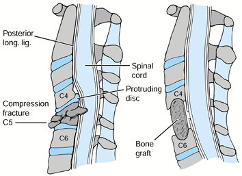 Figure 140.13.
Decompression of the cervical cord should include excision of the discs
above and below the burst fracture and the appropriate vertebral body. B: The endplates should be undermined to allow the tricortical iliac crest graft to be countersunk. -
An anterior cervical plate may be added
based on the amount of instability. Choose the length of the plate by
using the provided template. Place the plate in the appropriate
position, spanning the grafted area. Be sure that the longitudinal
center of the plate is midline, not displaced to one side or another. -
Position the drill guide in its correct
orientation, as dictated by the manufacturer’s instructions. Usually,
the drill guide is aimed medially 20°, with the sagittal angle
determined by the position of the plate. Drill to a preselected depth,
taking care to remain in bone at all times. -
After tapping, place the screw and
tighten moderately. Place two screws in each vertebral body at the ends
of the construct. Additional screws may be added in the graft. Tighten
all screws and engage the locking mechanism. Radiographic confirmation
of correct screw placement is advised. -
Place a large Penrose drain into the
depths of the wound. Close the platysma with interrupted sutures and
the skin with subcuticular sutures. Keep a tracheostomy set at bedside
for 48 hours in case of hematoma formation, which may obstruct the
airway. Remove drains at 48 hours. -
Keep the patient in traction overnight,
and then place the neck into a hard cervical collar or halo, depending
on the amount of instability and the stabilization achieved. Continue
immobilization for 3 months or until union is achieved.
lower cervical spine injuries can be numerous and involve many systems.
Comprehensive care must be given to prevent or minimize these
complications, especially those that may be iatrogenic in origin.
trauma victims at the time of initial evaluation to prevent neurologic
injury. Keep the patient immobilized at all times to prevent further
injury to the spinal cord or nerve roots. Placement of an orthosis or
halo apparatus must be done in an organized and efficient fashion to
avoid further damage.
is rare. However, overdistraction in a circumferential injury pattern
may be one cause. This is more common in patients with associated
cervical spondylosis and ankylosing spondylitis. It can be seen at any
time after injury and is usually secondary to ascending central
necrosis of the gray matter, with an enlarging central syrinx. The
diagnostic modality of choice is MRI.
as possible by traction or operative means. If the deformity is not
reduced, additional spinal cord or nerve root injury can occur by
compression or edema. In addition, compression of the radicular
arteries to the cord can precipitate ischemia and further worsen the
neurologic injury.
of the reduction because disc material and bone fragments may be pushed
into the canal, causing further neural injury. If the reduction is
performed nonoperatively, serial neurologic examinations provide
adequate information regarding neurologic function. If operative
reduction is required, neurologic monitoring (e.g., SSEPs or an
electromyogram) is useful. Should a neurologic deficit occur following
a closed or intraoperative reduction, operative decompression of the
affected area is indicated.
unilateral or bilateral facet dislocation, a prereduction MRI is
beneficial to identify extrusion of the disc material into the canal (22).
If this is found, the authors recommend an anterior discectomy prior to
reduction to minimize iatrogenic injury to the cord. A delay of
reduction to perform imaging is of little benefit to the patient with a
spinal cord injury (25). In cases with concomitant spinal cord injury, perform MRI after reduction. Carefully evaluate chronic
dislocations with an intact neurologic status prior to any treatment.
Operative fusion in the dislocated position may be required to prevent
neurologic injury caused by reduction.
nonoperatively or operatively to monitor for late instability and
deformity. Should this occur, operative intervention is required.
may result from paralysis of the intercostal muscles and diaphragm.
Hypoxia can ensue, requiring ventilatory support. Atelectasis and
pneumonia are common causes of morbidity and mortality and must be
treated aggressively.
vasomotor tone and use of their upper and lower extremities, venous
thrombosis and pulmonary embolism may be a problem. Emphasis should be
placed on the prevention of venous thrombosis with compression pump
stockings and other modalities. The use of prophylactic anticoagulants
is controversial.
found gastrointestinal hemorrhage to be a common problem. This occurred
most commonly 10–14 days after injury and was highly associated with
the use of steroids. Recovery in the groups treated with steroids did
not differ from that in the group treated without steroids.
complications, including excessive gastric secretions, gastric stasis,
and immobilization of the patients. Prophylactic care, including H2 blockers, can be useful in the prevention of upper gastrointestinal hemorrhage.
operations can cause sepsis or wound infections, which may result in
cervical osteomyelitis, meningitis, and death.
retraction or with instrumentation such as drill bits or screws. This
may result in dysphagia, fistula formation, and infection.
those of pathologic bone. Bone cement does not fuse with bone, and
fixation loosens with time, resulting in instability. Increased
infection rates have been associated with the use of cement.
compression is usually not helpful and may cause increased neurologic
deficit. Laminectomy can decrease stability and does not permit
retrieval of anterior fragments from the canal. Because sublaminar
wires take up space within the canal and can injure the spinal cord,
they are contraindicated in cervical spinal trauma.
patient is asleep, spinal cord monitoring may help detect the rare
complication of retropulsion of a ruptured disc causing spinal cord
compression. If monitoring is not used, an intraoperative wake-up test
may be performed. If there is a change in the neurologic status during
or after a posterior procedure, perform anterior decompression without
delay.
within the C-3 to C-7 levels is rare. In a review of 100 consecutive
patients, no nonunions or increased neural deficits were noted (52). Similar rates of fusion have been reported with anterior instrumented fusions (4,33,50).
spinal cord injury must be followed for skin breakdown if they are
placed in a two-poster orthosis or a halo jacket. Their insensate skin
can break down easily. The two-poster orthosis and Philadelphia collar
can cause breakdown over the chin region and therefore must be
carefully applied and followed.
Pressure sores must be prevented. Pin placement and care are important
when the ring is applied. Retorque the halo pins the day after
application and check them for looseness periodically thereafter. Pay
constant attention to the screws and rods to prevent loss of reduction.
of bone grafts and to look for loss of reduction. Before removing a
halo jacket, obtain flexion and extension radiographs, after the
connecting bars are loosened, to assess fusion and stability.
scheme: *, classic article; #, review article; !, basic research
article; and +, clinical results/outcome study.
M, Mohler J, Zach G, Morscher E. Indication, Surgical Technique and
Results of 100 Surgically Treated Fractures and Fracture Dislocations
of the Cervical Spine. Clin Orthop 1986;203:244.
BL, Ferguson RL, Lehmann TR, O’Brien RP. A Mechanistic Classification
of Closed, Indirect Fractures and Dislocations of the Lower Cervical
Spine. Spine 1982;7:1.
HH. Acute Fractures and Dislocations of the Cervical Spine: An Analysis
of 300 Hospitalized Patients and Review of the Literature. J Bone Joint Surg Am 1979;61:1119.
DW, Bellegarrigue R, Ducker TB. Bilateral Facet to Spinous Process
Fusion: A New Technique for Posterior Spinal Fusion after Trauma. Neurosurgery 1983;13:1.
DA, Nelson RW, Zigler J, et al. Surgical Stabilization of the Cervical
Spine: A Comparative Analysis of Anterior and Posterior Spine Fusions. Paraplegia 1987;25:111.
JD, Warden KE, Sutterlin CE, McAfee PC. Biomechanical Evaluation of
Cervical Spinal Stabilization Methods in a Human Cadaveric Model. Spine 1989;14:1122.
JM, Herbison GJ, Nasuti JF, et al. Closed Reduction of Traumatic
Cervical Spine Dislocation Using Traction Weights up to 140 Pounds. Spine 1993;18:386.
GR, Douglas RA, Meyer PR, Rovin RA. Complications in Three Column
Cervical Spine Injuries Requiring Anterior-Posterior Stabilization. Spine 1992;17:253.
FJ, Aruna MJ, Green BA. Extrusion of an Intervertebral Disc Associated
with Traumatic Subluxation or Dislocation of Cervical Facets. J Bone Joint Surg Am 1991;73:1555.
SL, Wolf AL, Ecklund J. Posterior Spinal Osteosynthesis for Cervical
Freacture/Dislocation Using a Flexible Multistrand Cable System:
Technical Note. Neurosurgery 1991;29:943.
PC, Bohlman HH, Wilson WL. The Triple-wire Fixation Technique for
Stabilization of Acute Fracture-Dislocations: A Biomechanical Analysis.
Orthop Trans 1985;9:142.
E, Sutter F, Jenny H, Olerud S. Die Vordere Verplattung der
Halswirbelsaule mit dem Hohlschrauben-Plattensystem aus Titanium. Chirurg 1986;57:702.
RA, Southwick WO. Indications and Techniques for Early Stabilization of
the Neck in Some Fracture Dislocations of the Cervical Spine. South Med J 1960;53:565.
R, Saillant G, Mazel C. Internal Fixation of the Unstable Cervical
Spine by a Posterior Osteosynthesis with Plates and Screws. In: The
Cervical Spine Research Society, eds. The Cervical Spine. Philadelphia: JB Lippincott, 1989:390.
M, Tress BM, Hennessy O. Prevertebral Swelling in Cervical Spine
Injury: Identification of Ligament Injury with Magnetic Resonance
Imaging. Clin Radiol 1992;46:318.
ES, Kelley EG. Fracture-Dislocation of the Cervical Spine: Instability
and Recurrent Deformity Following Treatment by Anterior Interbody
Fusion. J Bone Joint Surg Am 1977;59:45.
OC, Anbari MM, Pilgram TK, Wilson AJ. Acute Cervical Spine Trauma:
Diagnostic Performance of Single-View Verses Three-View Radiographic
Screening. Radiology 1997;204:819.
AA, Panjabi MM, Saha S, Southwick WO. Biomechanics of the Axially
Loaded Cervical Spine: Development of a Clinical Test for Ruptured
Ligaments. J Bone Joint Surg Am 1975;57:582.