MR Imaging of the Fingers


11 – MR Imaging of the Fingers

Chapter 11
MR Imaging of the Fingers
Jean-Luc Drap
Dominique Le Viet
Although MR examination of the fingers remains relatively uncommon, in many cases it is preferable to ultrasonography, which is limited by lack of bone assessment and poor tissue characterization of finger masses. Advances in the design of MR units and surface coils have resulted in improved quality of MR images of fingers. There are several finger disorders appropriate for MR imaging, including tendon and ligament injuries, finger masses, and inflammatory diseases.
MR Techniques in Finger Imaging
High-quality MR images of the fingers may be obtained with commercial MR units with high-field-strength systems (1.5 T and 3 T) and surface coils dedicated to wrist and/or finger imaging.1
Successful MR imaging of the fingers is more likely if the following conditions are met:
  • A 23-mm surface coil allows an 80 to 100 μm spatial resolution.2 When using a circular surface coil, the finger is placed through the coil to offer the maximum signal homogeneity. Larger coils, such as knee coils, may be necessary to image the whole wrist and hand for staging rheumatic diseases.
  • Ideally, the patient is placed in the prone position with the arm elevated. This puts the hand close to the center of the magnet to obtain efficient fat suppression. Full cooperation of the patient and efficient mechanical support with adhesive bandages are necessary. Some patients with painful (rotator cuff tears, multiple tendon calcifications) or frozen shoulders cannot maintain this position during the entire examination.
  • In all cases, finger immobility is necessary to avoid movement artifacts, which are particularly disturbing with high spatial resolution. Children younger than 6years of age usually cannot be examined in this manner.
  • Routine MR imaging of the finger is performed with axial images. This plane demonstrates mild partial volume artifact with 3- to 4-mm-thick slices and allows assessment of all the anatomic elements of the finger.
  • A complementary longitudinal plane image may be added, depending on the location of the suspected lesion.
  • Sagittal plane images are used to evaluate the extensor and flexor tendons, the volar plate, the pulleys, and the cartilage surfaces.
  • P.1848


  • Coronal plane images are used to evaluate the collateral ligaments and osteochondral structures.
  • A field of view of 2 to 4 cm for axial images is the most useful. It provides a whole view of the finger section while maintaining a sufficient signal-to-noise ratio (SNR).
  • Routine examination includes axial T1-weighted spin-echo images and axial fast STIR or fat-suppressed fast spin-echo T2-weighted images, completed with a longitudinal sequence.
  • The T1-weighted spin-echo sequence clearly delineates the major structures of interest within the distal interphalangeal (DIP) joint.3
  • Fat suppression is necessary for T2-weighted images because of the large amount of fat in the subcutaneous tissue of the fingers.
  • The confidence level of a diagnosis may be improved in traumatic lesions by post-gadolinium fat-suppressed T1-weighted imaging. Contrast administration is also necessary to assess the vascularization of tumors and pseudotumors with or without MR angiography.
  • 3D gradient-echo images are acquired when 1-mm-thick contiguous slices are necessary. However, small fields of view are limited with these sequences and multiplanar reformatting (MPR) is of poor quality because of the lack of isotropic acquisition.
  • 3D post-gadolinium coronal sequences are acquired for MR angiography, with sequential acquisitions during the arterial and venous phases.4,5,6
  • Elliptical centric acquisitions improve the arterial phase by reducing the venous contrast.
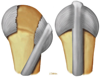
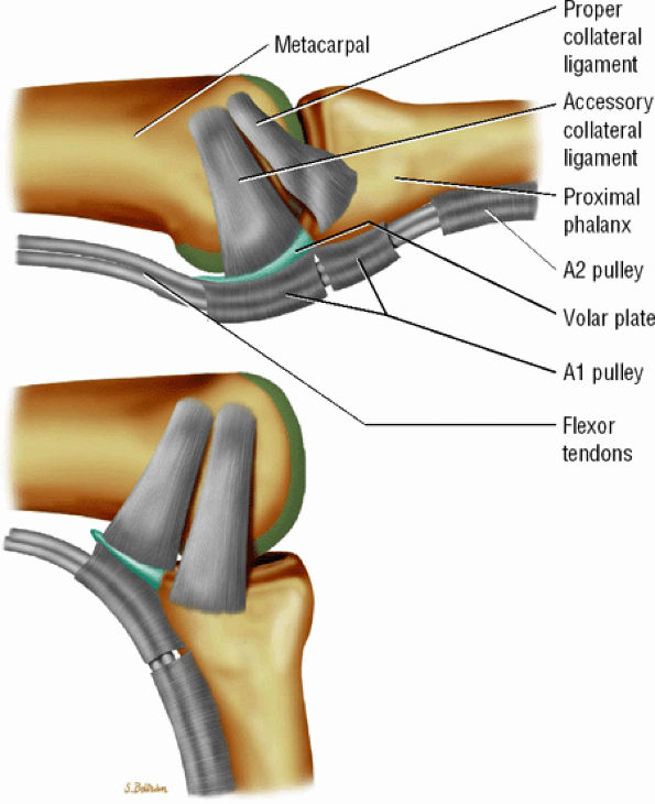
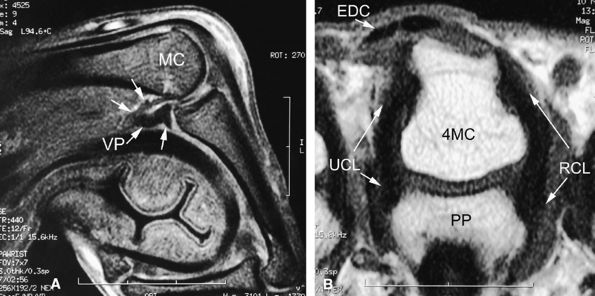
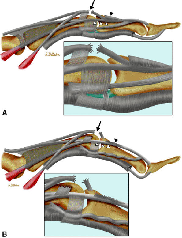
FIGURE 11.1 ● Capsular ligaments of the metacarpophalangeal joint. (A) Extension. The proper collateral ligament (PCL) is relaxed and the accessory collateral ligament (ACL) is under tension and limits extension. (B) Flexion. All ligaments are taut. The space between the A1 and A2 pulleys is narrowed.
Traumatic Finger Injuries
Ligaments
Sprains of the proximal interphalangeal (PIP) joints are common during sports activities and are most often managed on the spot without imaging. MR examination of the metacarpophalangeal (MP) joints is mainly focused on the first MP joint. Imaging of the DIP joint is used for evaluation of tendon and osteochondral injuries.
Metacarpophalangeal Joint
MP joint dislocations are uncommon, except for the thumb.7 Valgus or varus injuries on a flexed joint may produce a rupture of a collateral ligament,8 which can be confirmed by MR imaging when the diagnosis is uncertain. MR examination is also helpful in detecting complications, such as ligament entrapment9 or associated tears of the volar plate,10 which are clinically underestimated.
Normal Anatomy
The unicondylar anatomy of the MP joint allows flexion-extension as well as additional radial and ulnar deviation and some rotation. The collateral ligaments (both proper and accessory) are taut during flexion and lax during extension, allowing radial and ulnar deviation (Fig. 11.1).9,11
Important elements of the ligamentous anatomy of the MP joints of the fingers include the following:
  • The proper collateral ligament (PCL) originates from the dorsal side of the metacarpal head and extends

    P.1849


    obliquely and distally to insert onto a tubercle on the side of the base of the proximal phalanx. The radial PCL is stronger, and more oblique in its long axis, and its origin is a little closer to the articular surface than the ulnar PCL.

  • The accessory collateral ligament (ACL) has a common origin with the PCL and ends like a fan on the lateral side of the volar plate (Fig. 11.2). Some additional lateral stability is provided by the intrinsic tendons. This is especially important for the index finger (the first interosseous tendon on the radial aspect of the joint) and for the little finger (the abductor digiti minimi and flexor digiti minimi brevis on the ulnar side).
  • The volar plate is a fibrocartilaginous structure that becomes continuous with the articular surface on the palmar side (Fig. 11.3). The ACL is connected to the adjacent volar plate by the deep transverse metacarpal ligament. The volar plate is also connected to the flexortendon sheath (by the annular A1 pulley), strongly attached distally to the proximal phalanx, and loosely attached to the metacarpal neck by the checkreins.
  • The extensor hood, particularly the sagittal bands, stabilizes the MP joint and the extensor tendon during flexion (see Fig. 11.2).12
The MP joint of the thumb has a condylar pattern, allowing essential flexion-extension mobility and some degree of

P.1850


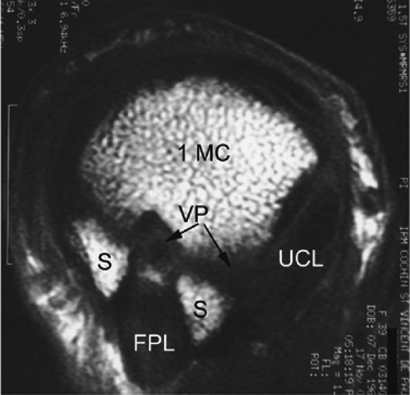
rotation. Stability is provided by the collateral ligaments, the volar plate, and musculotendinous elements. When the sesamoid bones are included in the volar plate, it is referred to as the volar complex (Fig. 11.4). On the medial aspect of the joint, the adductor pollicis is a strong insertion on the proximal phalanx and the volar plate, and contributes to the adductor aponeurosis. The ulnar collateral ligament (UCL) is covered dorsally by the adductor aponeurosis (Fig. 11.5).7,13

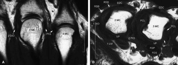
FIGURE 11.2 ● Metacarpophalangeal joints. (A) T1-weighted coronal image. (B) T1-weighted axial image. The proper collateral ligament (PCL) is lax in extension and shows heterogeneous signal intensity on coronal and axial images. ACL, accessory collateral ligament; VP, volar plate; LM, lumbrical; DIO, dorsal interosseous; PIO, palmar interosseous; MC, metacarpal; RSB, radial sagittal band; EDC, extensor digitorum communis; EIT, extensor indicis proprius tendon; FDS, flexor digitorum superficialis tendon; FDP, flexor digitorum profundus tendon; A1, A1 annular pulley.
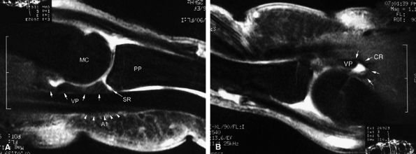
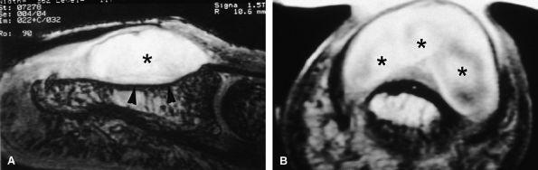
FIGURE 11.3 ● The volar plate of the metacarpophalangeal joint. (A) Midline and (B) parasagittal post-enhancement fat-suppressed sagittal T1-weighted images. VP, volar plate; SR, synovial recess; MC, metacarpal; PP, proximal phalanx; A1, A1 annular pulley; CR, checkrein.
FIGURE 11.4 ● Volar complex of the thumb. Axial T1-weighted images. Sesamoid bones (S) are incorporated into the volar plate (VP). FPL, flexor pollicis longus; UCL, ulnar collateral ligament; 1MC, first metacarpal.
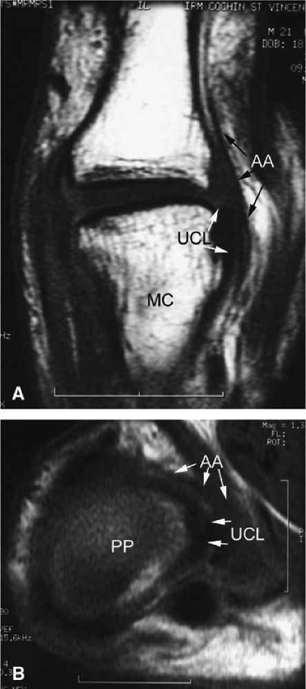
FIGURE 11.5 ● Coronal (A) and axial (B) T1-weighted images showing the ulnar collateral ligament (UCL) and adductor aponeurosis (AA). The UCL is deeper than the AA on axial images. On coronal images, the oblique AA is often more visible distal to the UCL. MC, metacarpal; PP, proximal phalanx.
Gamekeeper's Thumb
Injury of the UCL of the first MP joint is common and is called gamekeeper's thumb or skier's thumb. A missed diagnosis may lead to chronic laxity and even to osteoarthritis. The UCL is usually torn at its distal insertion during a forced valgus mechanism. If bony avulsion occurs, surgical repair is necessary. A completely torn UCL may remain beneath the adductor aponeurosis with a mild retraction. In more severe injuries, the torn UCL may retract proximally and superficially above the adductor aponeurosis; this is called a Stener's lesion (Fig. 11.6).14 Stener's lesions need to be repaired surgically because of the interposition of the aponeurosis and the risk of chronic instability.
Although complete tears can be differentiated from partialtears on clinical examination, differentiation of nondisplaced tears from a Stener's lesion is more difficult.15 In both cases there is a palpable mass in the ulnar aspect of the first MP joint and radial stress shows 30 degrees or more of instability compared with the contralateral thumb.13 With stress

P.1851


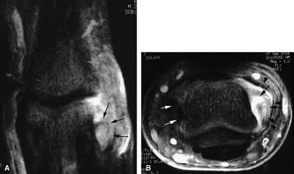
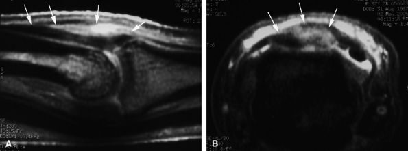
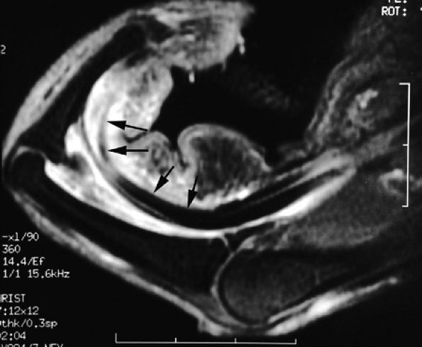
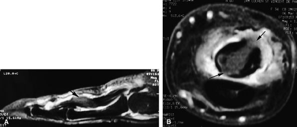
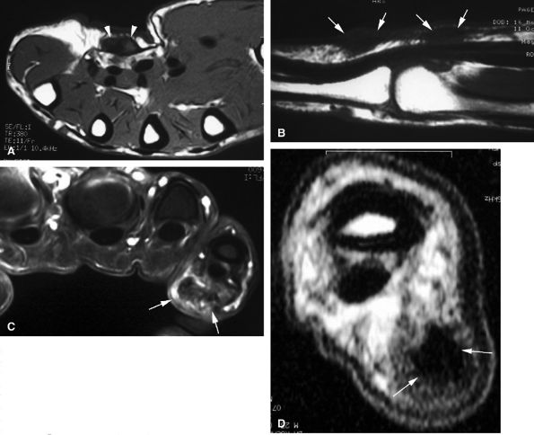
maneuvers alone a nondisplaced lesion may be misdiagnosed as a displaced one, and both ultrasonography and MR imaging may be useful (optimally before 2 weeks) in making the diagnosis.16 MR imaging and MR arthrography are both accurate in the detection of a Stener's lesion.15,17,18,19 Coronal fast spin-echo T2-weighted images are the most informative.20,21 The identification of a displaced versus a nondisplaced ligament is not straightforward, and a spectrum of UCL injuries may be depicted. Differentiation is more difficult in chronic lesions.20,22 Characteristic MR findings include the following:

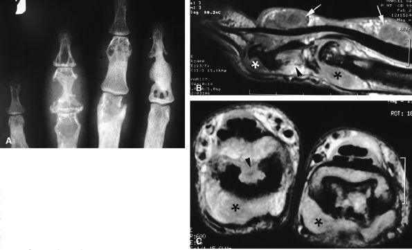
  • The UCL lies deep to the overlying low-signal adductor aponeurosis on coronal images (Figs. 11.7 and Fig. 11.8). In a nondisplaced partial or complete tear of the UCL, the ligament appears thickened all along its course, sometimes with a small gap. When displaced, the UCL appears as a proximally retracted round or stump-like structure, which demonstrates low signal on all sequences. It is no longer parallel to the long axis of the thumb and presents an increased horizontal orientation.
  • Stener's lesion may present with a “yo-yo on a string” pattern, with the retracted and balled-up UCL representing the yo-yo and the more distal linear adductor aponeurosis representing the string (Fig. 11.9).
  • On axial images, the ligament may be seen lying above or intersecting the adductor aponeurosis.
Radial collateral ligament (RCL) injuries are much less common (14%) and the clinical diagnosis is more difficult because there is less laxity on the radial side of the MP joint.7 The avulsion of the RCL is more often proximal (Fig. 11.10). If the avulsion is distal, a phenomenon similar to Stener'slesion may occur over the lateral band of the abductor pollicis brevis. This lesion also requires surgical intervention.
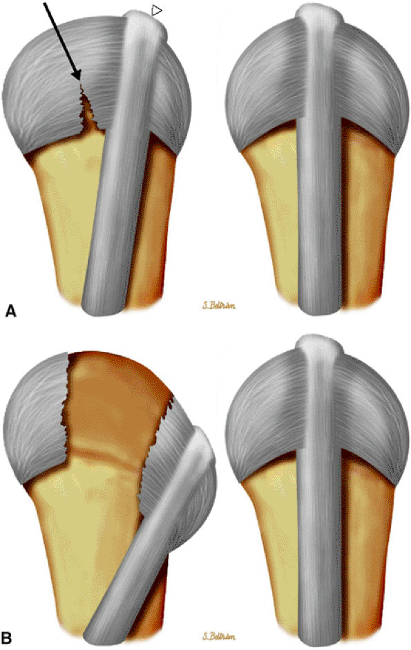
FIGURE 11.6 ● Stener's lesion. The ulnar collateral ligament (UCL) is torn from its distal insertion and the proximal end passes over the expansion of the adductor pollicis aponeurosis and cannot heal.
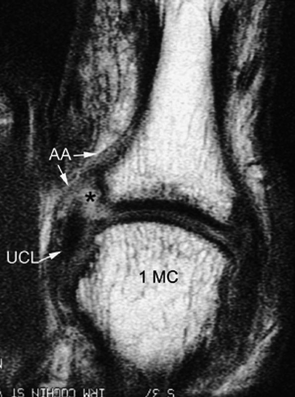
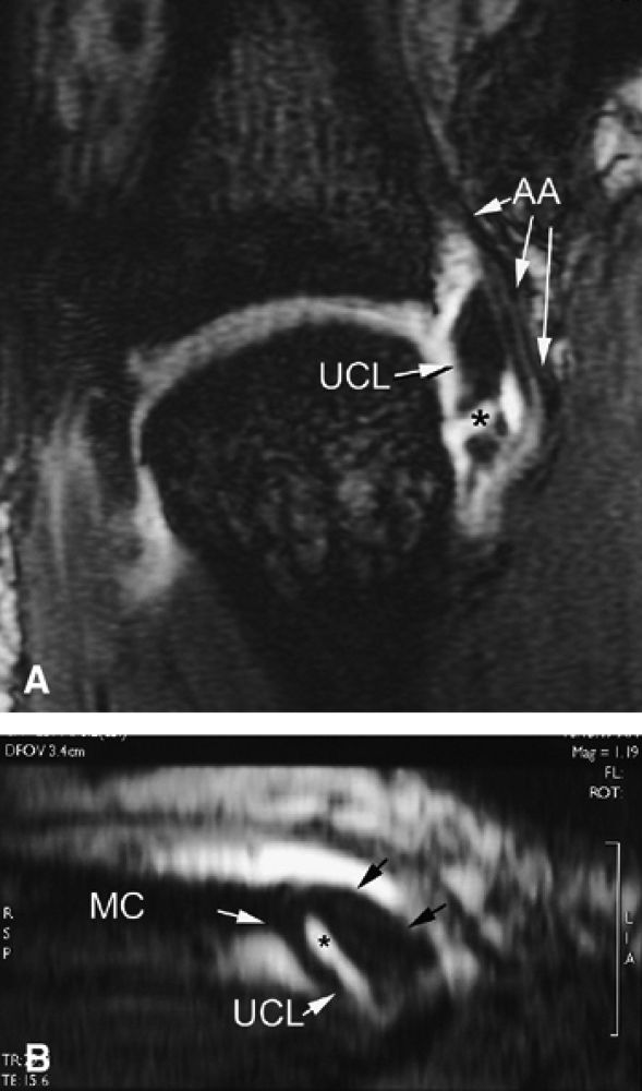
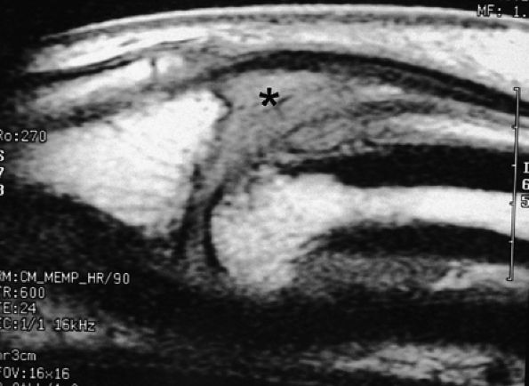
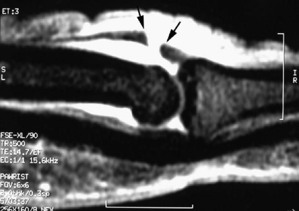
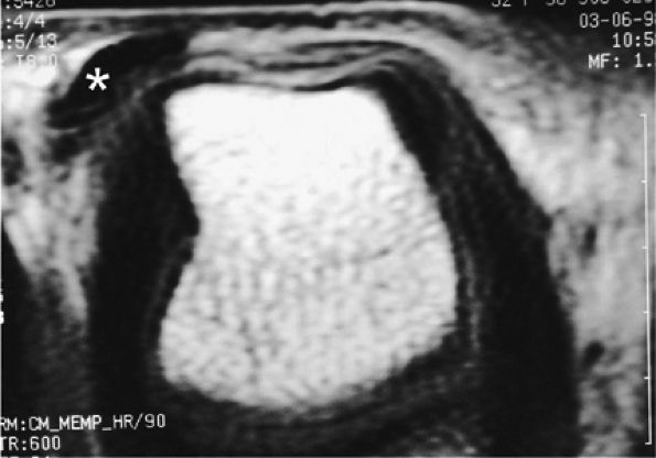
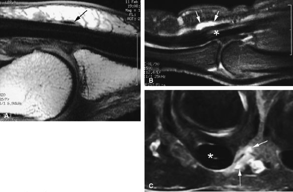
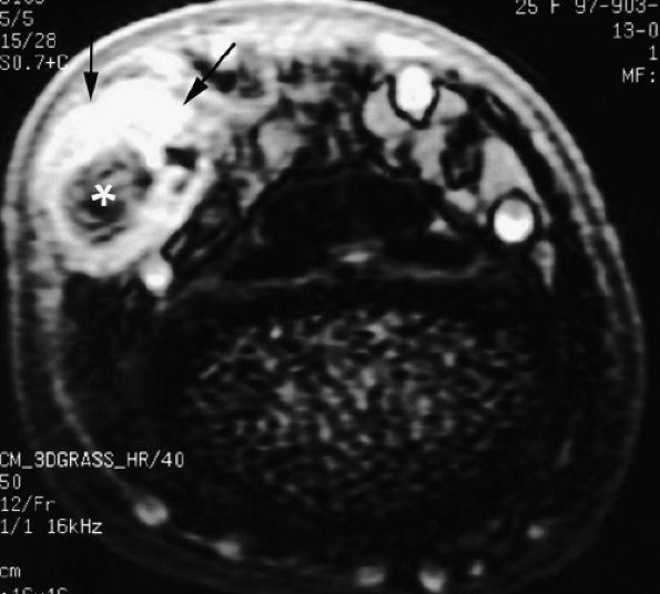
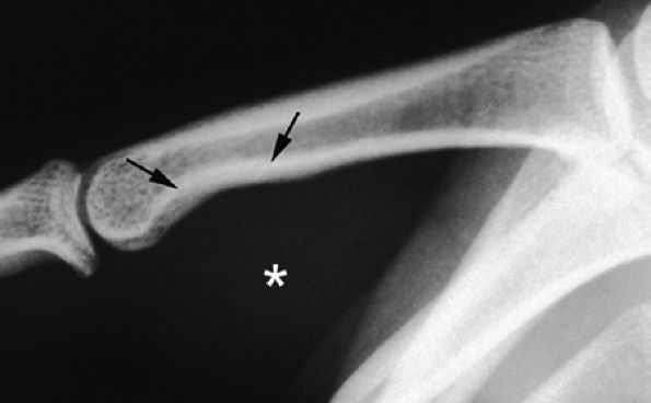
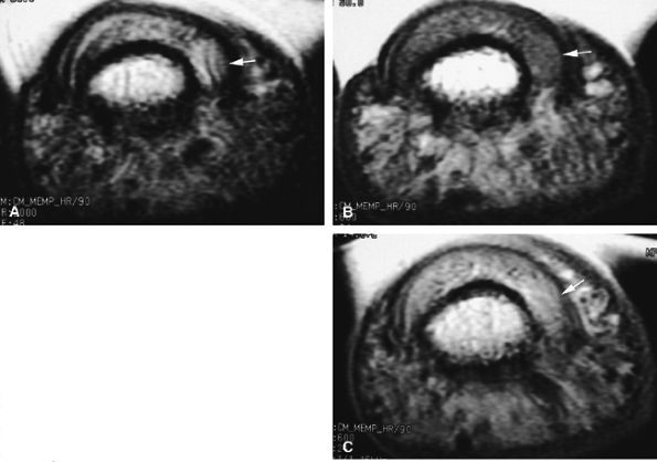
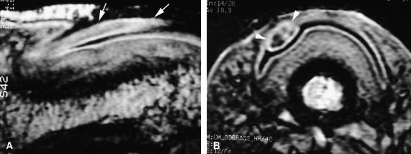
FIGURE 11.7 ● Coronal post-contrast T1-weighted image showing a nondisplaced tear of the UCL of the first metacarpophalangeal joint (MP) joint. The torn UCL is elongated beneath the adductor aponeurosis (AA). There is focal enhancement of the tear (asterisk). 1 MC, first metacarpal.
II–V MP Joints
Injuries of the collateral ligaments of the II–V MP joints are rare and involve mainly the RCL due to a sudden ulnar deviation or a forced twisting of the finger.23,2425 Because of the lack of an adjacent finger on the radial aspect of the index finger, such stress may produce injuries of the UCL. Ligament stability must be tested with the joint in the flexed position, because in the extended position the joint is normally lax. A complete tear of the collateral ligament is suspected in cases of gross instability without a firm end-point.9,23 In emergency evaluation, routine PA and oblique radiographs are often normal or may show a bony avulsion.26 Ifthere is no bone fragment, comparative views with lateral stress in a flexed joint can demonstrate a ligament rupture, but these are difficult to perform. The II–V MP joints are less accessible to ultrasound evaluation than that of the thumb, and the accuracy of ultrasonography in diagnosing collateral ligament injuries has not been demonstrated.27
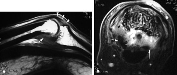
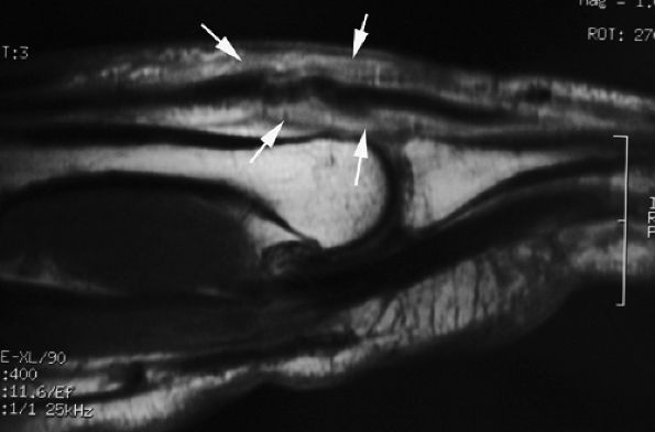
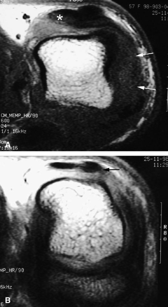
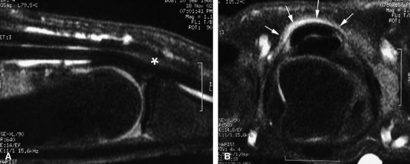
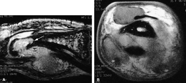
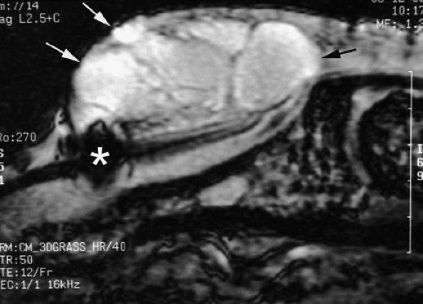
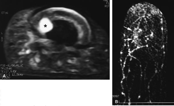
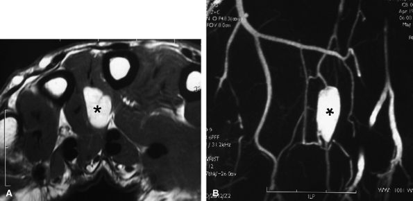
FIGURE 11.8 ● MR arthrography of nondisplaced tear of the UCL of the first MP joint. Coronal (A) and sagittal multiplanar reformatted (MPR) (B) T1-weighted fat-suppressed 3D gradient-echo images showing an oblique tear (asterisk) of the UCL without avulsion. Thearrows mark the distal (black) and proximal (white) aspects of the torn UCL. The sagittal MPR slice is defined along the course of the UCL. MC, metacarpal; AA, adductor aponeurosis.

P.1852


P.1853


In chronic posttraumatic disability of the MP joints, MR imaging is useful in delineating abnormalities of the collateral ligaments (Fig. 11.11). Axial T2-weighted images are more accurate than coronal images, but accurate depiction requires that imaging be performed with the MP joint in a flexed position. MR findings include:
  • The collateral ligaments are taut and visible all along their course (Fig. 11.12).28,29,30,31
  • Stress imaging also allows assessment of the stability of the extensor tendon.28 When injured, the ligament appears thickened all along its course, but the presence of fluid in a tear is uncommon in chronic lesions.
  • Intravenous injection of gadolinium may increase image contrast, making it possible to visualize small ligament tears (Fig. 11.13).10 Tears may involve the distal or proximal insertion or the middle third of the ligament (Figs. 11.13 and Fig. 11.14).
  • A ligament displacement with a pseudo-Stener's lesion is rare but should be suspected if a round retracted ligament is seen. A torn ligament may be trapped by the

    P.1854


    proximal portion of the extensor hood and a sagittal band.23,25

  • MR imaging also depicts common associated lesions (extensor hood, volar plate) in more than 40% of cases (Fig. 11.15).10
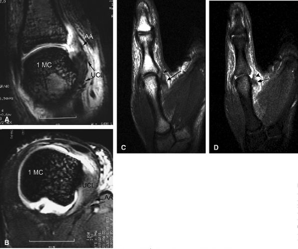
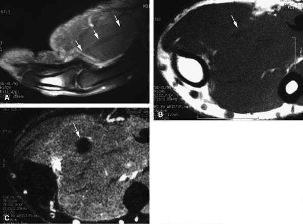
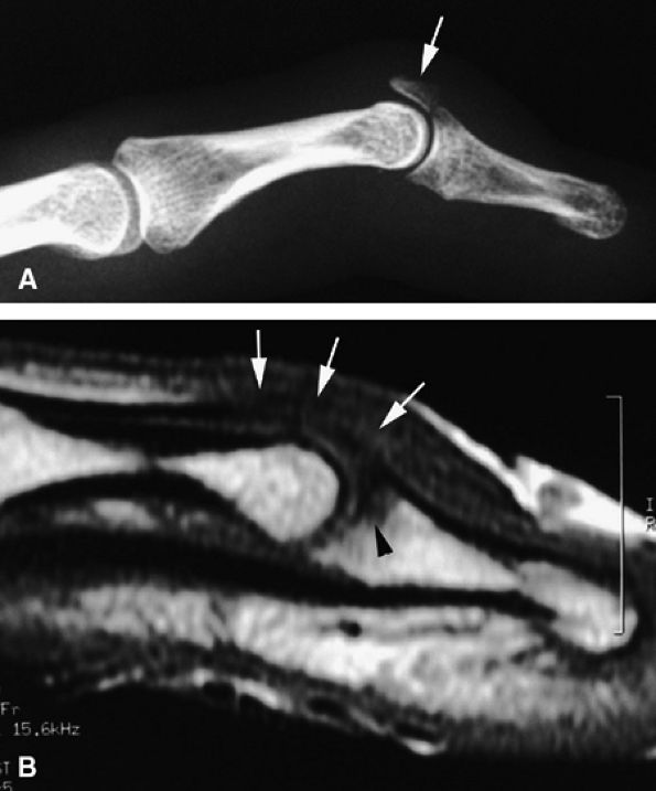
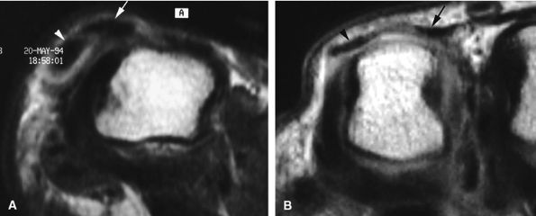
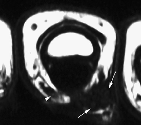
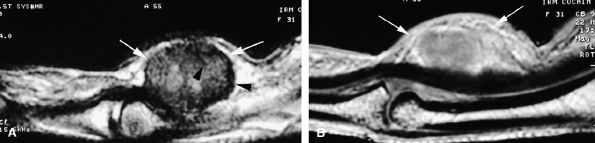
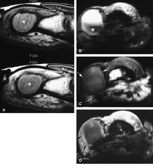
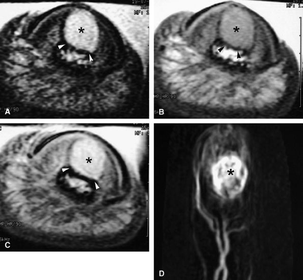
FIGURE 11.9 ● MR of Stener's lesions. MR arthrograms. Coronal (A) and axial (B) T1-weighted fat-suppressed 3D gradient-echo images. The UCL is retracted proximally with a mildly horizontal orientation. The adductor aponeurosis (AA) is partially beneath the UCL. 1 MC, first metacarpal. A more classic Stener's lesion depicted on a coronal proton density-weighted image (C) and a fat-suppressed coronal proton-density weighted image (D), which demonstrate the UCL (arrow) torn from its distal attachment and extending perpendicular to the first ray. The adductor aponeurosis (arrowhead) is seen as a linear structure distal and deep to the torn and retracted UCL.
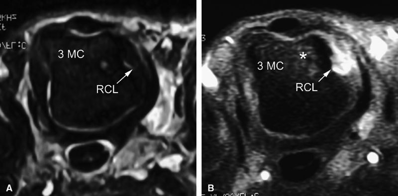
FIGURE 11.10 ● Coronal T1-weighted image showing an injury of the radial collateral ligament (RCL) of the first MP joint. The RCL demonstrates increased signal intensity and thickening all along its course.
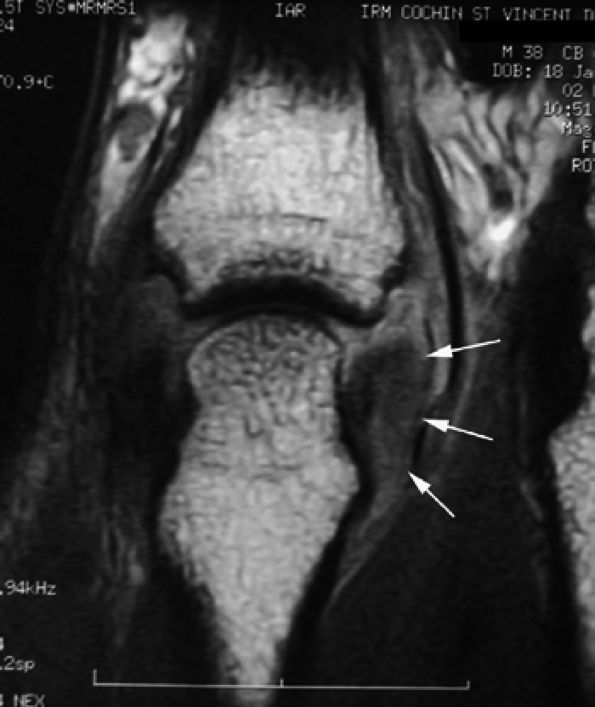
FIGURE 11.11 ● Tear of the radial collateral ligament (RCL) of the fifth metacarpophalangeal joint is shown on this coronal post-contrast T1-weighted image. The distal insertion of the RCL is proximally retracted and thickened (arrows).
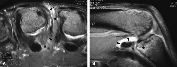
FIGURE 11.12 ● Stress MR examination with flexion of the metacarpophalangeal joint. (A) Sagittal fat-suppressed T1-weighted and (B) axial fast spin-echo T2-weighted images show the taut radial and ulnar collateral ligaments (RCL and UCL), which are seen along their course with a low signal. The stability of the extensor digitorum communis (EDC) tendon can also be assessed on these images. The volar plate (VP) is lax. MC, metacarpal; PP, proximal phalanx.
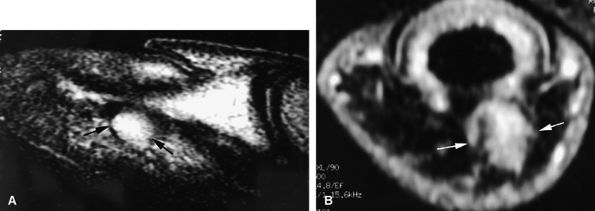
FIGURE 11.13 ● Proximal tear of the radial collateral ligament (RCL) of the third metacarpophalangeal joint. Comparison of axial STIR (A) and post-contrast fat-suppressed T1-weighted image (B). Focal irregularity and slight hyperintensity of the RCL can be seen on the STIR image. Strong enhancement of the proximal part of the RCL and bone edema (asterisk) is seen on the T1-weighted images. MC, metacarpal.
FIGURE 11.14 ● Collateral ligament tear of the metacarpophalangeal joint. Axial post-contrast fat-suppressed T1-weighted images with flexion of the joint. (A) Tear of the middle third of the ligament (arrow). (B) Distal tear (arrow) with a slight tilt of the volar plate (asterisks). There is associated contralateral bone edema of the metacarpal head (arrowhead).
Proximal Interphalangeal Joint
PIP joint sprains are very common and are usually considered irrelevant and are therefore underrated or misdiagnosed. As a result, these theoretically benign lesions can be transformed into a painful, stiff joint or even into an unstable one.
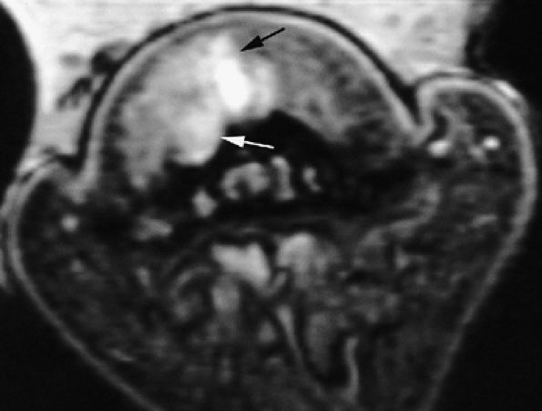
FIGURE 11.15 ● Axial (A) and sagittal (B) post-contrast fat-suppressed T1-weighted images display associated injuries of the ulnar collateral ligament (arrows) of the third metacarpophalangeal joint and the volar plate (arrowheads). Bone edema (asterisk) of the base of the proximal phalanx at the distal insertion of the volar plate can be seen.
Normal Anatomy
The bicondylar anatomy of the PIP joint allows a wide range of flexion and extension. The main stabilizers are the collateral ligaments and the volar plate.32 Dynamic stability is also provided by the extensor and flexor tendons and the retinacular ligaments. Important anatomic features include:
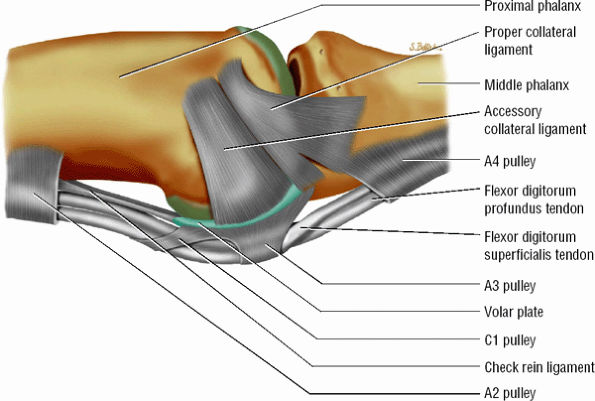
  • The collateral ligament complex is composed of a PCL and an ACL, both of which originate from the dorsolateral aspect of the head of the proximal phalanx; they insert on the laterovolar aspect of the base of the middle phalanx and the volar plate, respectively.
  • P.1855


  • The triangular shape of the PCL, with the vertex proximally located and the base distally located, predisposes its fibers, which are 2 to 3 mm thick, to be under constant tension. The dorsal components are under tension when the PIP is flexed, the palmar components when the joint is extended.
  • The most palmar component of the PCL has a partial attachment on the border of the volar plate in continuity with the ACL (Fig. 11.16).33
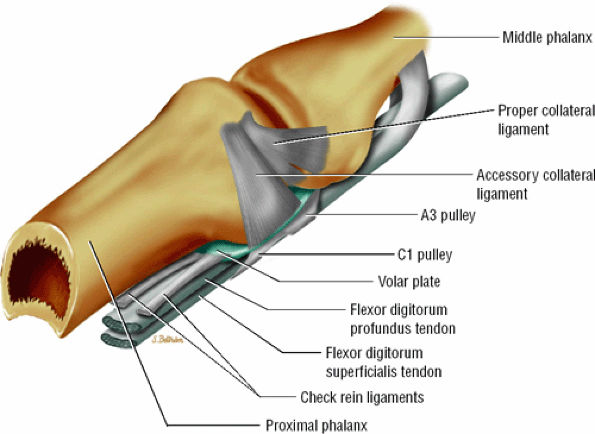
  • The volar plate reinforces the palmar aspect of the joint capsule and prevents hyperextension of the PIP joint. Its distal attachment to the base of the middle phalanx is thick, whereas its proximal attachment is divided in two U-shaped checkreins (Fig. 11.17).34
  • The extensor tendon complex stabilizes the PIP joint dorsally. The central slip inserts onto the dorsal tubercle of the base of the middle phalanx and is connected to the two lateral bands of the extensor tendon by retinacular ligaments (Landsmeer's oblique and transverse bands) (Fig. 11.18).
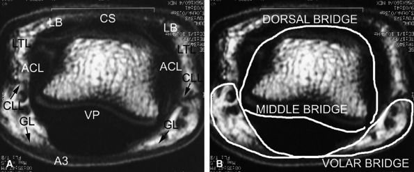
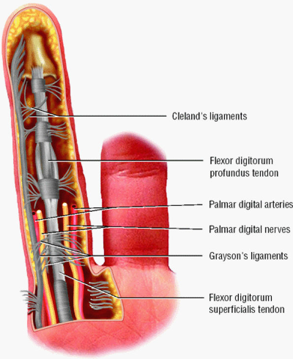
  • A complex retinacular apparatus includes the Landsmeer'sligament and cutaneous ligaments (Cleland's and

    P.1856


    Grayson's ligaments) (Fig. 11.19). It delineates three compartments (dorsal, volar, and laterovolar), forming three bridges (see Fig. 11.18). The dorsal bridge includes the median slip and the lateral bands of the extensor tendon, the Landsmeer's transverse ligament and the ACL. The volar plate constitutes the middle bridge. The volar bridge is formed from the annular A3 pulley, and Cleland's and Grayson's ligaments.

FIGURE 11.16 ● Capsular ligaments of the proximal interphalangeal joint. The proper collateral ligament inserts on the base of the middle phalanx and partially on the volar plate. The accessory collateral ligament inserts on the lateral aspect of the volar plate and flexor tendon sheath.
FIGURE 11.17 ● Oblique view of the volar plate. The proximal volar plate inserts with the checkrein ligaments on each side of the flexor tendon sheath close to the distal fibers of the A2 pulley.
FIGURE 11.18 ● (A) Axial T1-weighted images showing the retinacular apparatus at the level of the PIP joint. The dorsal bridge consists of the central slip (CS) and the lateral bands (LB) of the extensor tendon, Landsmeer's transverse ligament (LTL), and the accessory collateral ligament (ACL). The middle bridge consists of the volar plate (VP). The volar bridge consists of the A3 annular pulley (A3) and Cleland's and Grayson's ligaments (CLL and GL). (B) The finger is divided into a dorsal compartment with the PIP joint, a volar compartment with the flexor tendons, and two laterovolar compartments with the proper digital neurovascular bundles.
FIGURE 11.19 ● The cutaneous (Grayson's and Cleland's) ligaments. On this palmar view of the little finger, the ligaments are interlaced transverse and oblique fibers of connective tissue coursing between the skin and the flexor tendon sheath.
Therefore, the finger is divided into a dorsal compartment with the PIP joint, a volar compartment with the flexor tendons, and two laterovolar compartments with the proper digital neurovascular bundles.35
Lateral Instability
Collateral ligaments may be injured during forced valgus or varus stress of an extended joint. Three grades of injury are described:
  • Ligamentous sprain without joint instability
  • Partial tear with laterolateral instability
  • Complete tear with major instability or dislocation, which may be associated with a distal avulsion of the volar plate
Treatment is usually conservative but remains debated in some cases.8,36,37
MR imaging of the collateral ligaments of the PIP joint is performed with the joint extended to put the PCL under tension. Coronal and axial T2-weighted images are the most informative. MR findings of collateral ligament tear are not specific and include the following:
  • Thickening and intraligamentous signal abnormalities, periligamentous edema and swelling, discontinuity, detachment, and bone edema are seen at the insertion site (Fig. 11.20).
  • P.1857


  • Joint fluid leakage is uncommon and visible only in acute injuries.
  • In chronic injuries, the ligament is often continuous but thickened by scar tissue. Sometimes the ligament is thinned or demonstrates a wavy pattern.
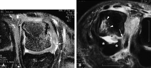
FIGURE 11.20 ● Acute injury of the radial collateral ligament (RCL) of the PIP joint of the fourth finger. Coronal (A) and axial (B) post-contrast fat-suppressed T1-weighted images displaying distal avulsion of the RCL with a proximal retraction (black arrows). The retinacular apparatus is displaced (arrowheads) with periligamentous edema. The ulnar collateral ligament is also identified (white arrows).
Unlike the MP joints, the collateral ligaments of the PIP joints can be successfully evaluated with dynamic ultrasound under valgus and varus stress.
Sagittal Instability
Instability in the sagittal plane is due to hyperextension or rotational longitudinal compression injuries.38 Hyperextension is the most common mechanism in sagittal instability, and the resulting dorsal articular displacement has been classified into three grades:32
  • Grade 1. Grade 1 injuries with distal avulsion of the volar plate from the base of the middle phalanx are relatively common, with a natural outcome of hyperextension of the PIP joint (swan neck deformity). Proximal avulsion of the checkreins is less common and may produce a pseudoboutonnière deformity with integrity of the extensor tendon.8 MR examination highlights volar plate injuries, depicting a range of findings from a simple thickening and blurring, to elongation and irregularities, to a complete rupture (Fig. 11.21).

    P.1858


    Sagittal and axial plane images are complementary. The normal synovial recess at the distal insertion of the volar plate must not be confused with a tear (see Fig. 11.3). The volar plate is also easy to assess with ultrasonography, which allows a useful dynamic study with flexion-extension of the joint.

  • Grade 2: In grade 2, the volar plate injury extends toward the collateral ligaments and dorsal subluxation produces more severe instability. MR images may reveal detachment of the collateral ligament from the volar plate, which causes volar plate tilting (Fig. 11.22).
  • Grade 3: Grade 3 represents fracture–dislocation of the distal attachment of the volar plate. A fragment involving less than 40% of the articular surface with integrity of the collateral ligament attachment is a stable injury. A larger bony fragment involving the volar plate and the collateral ligament insertions is unstable, producing dorsal subluxation.
FIGURE 11.21 ● Sagittal T1-weighted images at the site of a volar plate injury of the PIP joint. The volar plate is absent. Note the associated injury of the dorsal capsule, which appears thickened (asterisk).
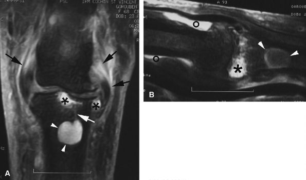
FIGURE 11.22 ● Associated injuries of the volar plate and a collateral ligament of the PIP joint. (A) Sagittal T1-weighted and (B) axial post-contrast fat-suppressed T1-weighted images show proximal injury of the checkreins of the volar plate with associated synovitis (white arrows). Continuity of the central slip of the extensor tendon is seen (arrowheads), and there is a tear of the radial collateral ligament (asterisk).
Treatment is conservative in most cases, except for unstable grade 3 lesions.39,40
The second mechanism of injury is rotational longitudinal compression of a semiflexed PIP joint. These injuries result in volar subluxation of the middle phalanx, with injury of the volar plate and unilateral tearing of the collateral ligament.36 The extensor tendon may also be involved in this severe injury with an elongation or tear of the central slip. MR imaging is useful for assessment of the severity of the tendon injury, as discussed below in the section on Extensor Tendons.
Tendons
Injuries of the tendons of the fingers are common and mayinvolve the extensor apparatus, the flexor digitorum superficialis (FDS) and profundus (FDP) tendons. Injuries may be closed with tendon avulsions, or open with tendon lacerations, as might be seen in glass or knife injuries. Initial evaluation is with plain films, which are necessary to quickly identify a bony avulsion that requires surgical reattachment.41 Most radiographs, however, do not show the bony avulsion, and ultrasonography or MR imaging may be necessary. These imaging modalities are also needed to locate the tendon ends and to measure the length of the gap before the occurrence of scar adhesions. Although 3D CT imaging with volume rendering has also been proposed for evaluation of these injuries, further studies are needed to confirm its usefulness.42 MR imaging is also useful in identifying postoperative complications, which are difficult to manage clinically.
Techniques for and findings of MR evaluation of tendon injuries include the following:
  • Large fields of view may be necessary because tendon retraction is often extensive.
  • Examination with the surface coil in two different locations is sometimes required.
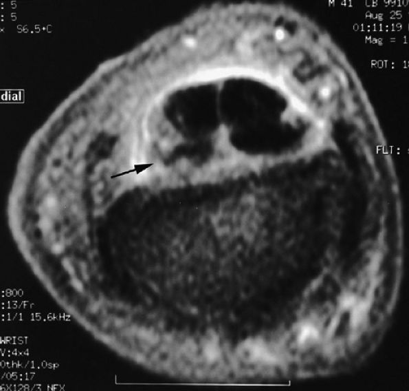
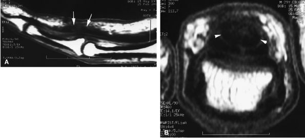
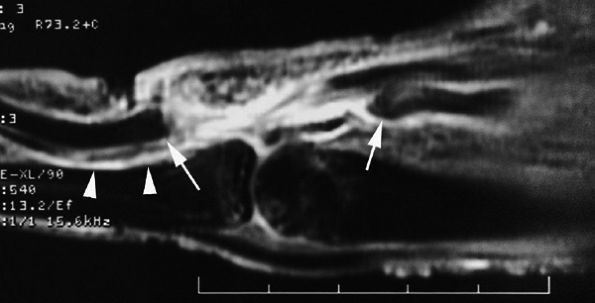
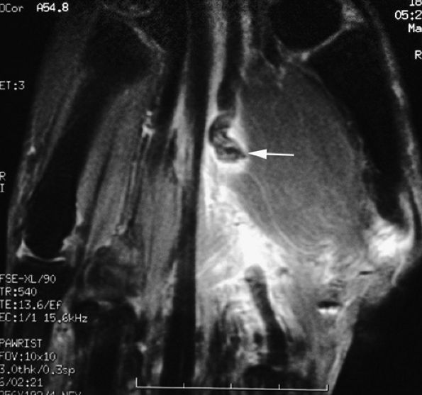
  • Axial and sagittal T1-weighted image or fat-suppressed proton density-weighted images may be sufficient to assess the tendon injury.43 However, when a short echo time (TE) is used, these sequences are subject to the magic angle phenomenon, which is most noticeable when the flexor or extensor tendon approaches an angle of 55 degrees with the B0 magnetic field. The magic angle phenomenon appears as increased intratendinous signal intensity that is present on all image planes and that decreases when TE values are lengthened.44 This artifact is relatively easy to recognize and typically occurs in areas such as the terminal band of the extensor tendon, the periarticular course of the flexor digitorum tendons, and the flexor pollicis longus in the thenar eminence (Fig. 11.23). In doubtful cases an additional T2-weighted sequence should be acquired.
  • P.1859


  • Sagittal 3D gradient-echo sequences allow oblique reformats along the long axis of the tendons. These images are also subject to the magic angle phenomenon and to magnetic susceptibility artifacts due to micrometallic deposits from suture placement.45
FIGURE 11.23 ● Magic angle phenomenon. The flexor pollicis longus tendon (arrows) with high signal intensity with short TE sequences on all imaging planes, as seen on (A) a sagittal fat-suppressed T1-weighted image and (B) an axial T1-weighted image. (C) On images with long TEs or STIR images, the signal of the tendon becomes normal.
Extensor Tendons
The extensor apparatus is thin and superficial and therefore is susceptible to lacerations or avulsions.
Normal Anatomy
Extension of the fingers is provided by the simultaneous action of extrinsic and intrinsic extensor muscles. The extrinsic muscles, which originate in the lateral aspect of the elbow and the forearm and insert in the hand, participate in the extension of all finger joints, but particularly the MP joints.38 These muscles include:
  • the extensor digitorum communis (EDC)
  • the extensor indicis proprius (EIP)
  • the extensor digiti quinti minimi (EDQM)
The intrinsic muscles (the interosseous and the lumbrical muscles) originate and insert in the hand (see Fig. 11.2; Fig. 11.24) and participate in extension of the PIP and DIP joints and flexion of the MP joints.
Numerous elements make up the extensor tendon, or more precisely the extensor apparatus, and anatomic variations are common and multiple. The anatomic features of the extensor apparatus include the following:
  • The juncturae tendinum (usually lacking for the extensor indicis tendon) connect the extensor tendons at the midpart of the metacarpals, preventing independent extension of the fingers (Fig. 11.25).46
  • In the most common configuration, the EDC provides one tendon to the index finger, one to the middle finger, two to the ring finger, and none to the little finger.47 The EIP tendon exhibits one tendon, whereas the EDQM exhibits two tendons (see Figs. 11.2 and Fig. 11.25). The EIP may be absent and the EDQM may provide a tendon slip to the ring finger.
  • The tendons are stabilized on the dorsal aspect of the MP joint by the extensor hood, the main elements of which are the sagittal bands. The radial and ulnar sagittal bands surround the extensor tendon and extend volarly toward the volar plate, coursing superficially to the collateral ligaments (see Figs. 11.2 and Fig. 11.25; Fig. 11.26). The sagittal bands also appear to envelop the superficial interosseous tendons on both sides.12 They glide with the extensor apparatus, and the orientation of their fibers changes as the finger moves.48
  • Distal to the sagittal bands, the interosseous and lumbrical transverse fibers contribute to the extensor hood. Therefore, at the midpart of the proximal phalanx, both

    P.1860


    P.1861


    P.1862


    intrinsic and extrinsic tendons contribute to the extensor apparatus.

  • The extensor tendon provides the central slip and the lateral bands (Fig. 11.27). The intrinsic tendons contribute to the lateral bands primarily, and to a lesser degree to the central slip.
  • The central slip inserts on the dorsal tubercle of the base of the middle phalanx. Once the lateral band receives its intrinsic contribution, it becomes a conjoint tendon and converges distally to form the terminal tendon with the contralateral band on the base of the distal phalanx.
  • The triangular ligament joints the two conjoint tendons and maintains them dorsal to the rotational axis of the PIP joint (see Fig. 11.27).
  • The tendons of the extensor apparatus are connected by the retinacular ligament (Landsmeer's ligament) at the level of the PIP joint and the middle phalanx (see Fig. 11.18).
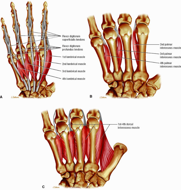
FIGURE 11.24 ● Intrinsic muscles of the hand. (A). Palmar view of the most common configuration of the lumbrical muscles. (B) Palmar view of the palmar interossei muscles. (C) Palmar view of the dorsal interossei muscles.
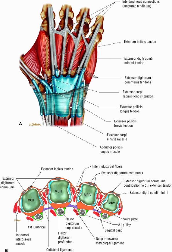
FIGURE 11.25 ● Extensor tendons and their interconnections (juncturae tendinum). (A) Dorsal aspect and (B) axial image at the metacarpal heads. The most common configuration is presented. The extensor indicis tendon (EIT) lacks a junctura tendinum.
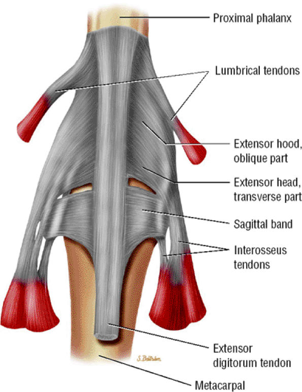
FIGURE 11.26 ● Extensor hood and sagittal bands. Dorsal aspect.
Extensor Tendon Injuries
Flexor tendon injuries may be classified as either open or closed. Because of the complex structure of the extensor apparatus and the frequency of injuries, the use of an anatomic zone classification is useful in categorizing them. One of the more common classifications consists of six zones, from the DIP joint (zone I) to the dorsum of the hand and wrist (zone VI) (Table 11.1).49,50 Associated lesions of the extensor apparatus and the joint elements may be caused by periarticular injuries.50
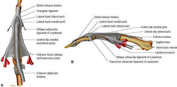
FIGURE 11.27 ● Extensor apparatus of the finger. (A) Dorsal aspect and (B) radial aspect.
TABLE 11.1 ● Zone Classification of Extensor Tendon Injuries
Zone Injury
Zone I: DIP joint An open mallet finger is a deformity with flexion of the DIP joint due to a laceration of the terminal band of the extensor tendon.
Zone II: Middle phalanx At this level the lateral bands are traveling in a volar to dorsal direction and are merging with fibers of the central slip. Usually tendon lacerations in this location are partial.
Zone III: PIP joint A boutonnière deformity may be secondary to a laceration of the central slip of the extensor tendon.
Zone IV: Proximal phalanx At this level there is only 2 to 3 mm of tendon excursion, and minor amounts of adhesion can result in significant amounts of loss of extension. The lateral bands are usually spared in this location due to their volar location.
Zone V: MP joint At this level, examination of tendon injury may be confounded by the normal action of the hand intrinsics. Besides lesions of the EDC tendon, sagittal band injuries may also occur and require individual repair. There is a risk of tendon subluxation or dislocation in this zone.
Zone VI: Dorsum of hand and wrist  

P.1863


Open Injuries
The MR appearance of open extensor injuries is distinct.
  • A partial tendon laceration appears as a thickened continuous tendon on sagittal and axial images, with partial intratendinous signal abnormalities. In evaluation of acute soft tissue injury associated with edema, T2-weighted and post-gadolinium-enhanced T1-weighted images are important (Fig. 11.28).
  • A complete laceration is highlighted by a tendinous gap, and the tendon ends are usually irregular, with some fraying. The length of the gap can be measured on sagittal images (Fig. 11.29). Tendon retraction is usually limited due to the numerous retinacular connections.50
In chronic injuries MR imaging can detect peritendinous adhesions blurring the fatty tissue. Enhancement of scar tissue is variable, and tendon displacement or a loss of tension may be visualized (Fig. 11.30). The rich vascular supply of tendons favors extensive peritendinous adhesions between the injured tendon and the underlying bone or joint. The need for surgical repair of partial lacerations proximal to the MP joint remains debated. Lacerations at or distal to the MP joint level, however, must be repaired.51
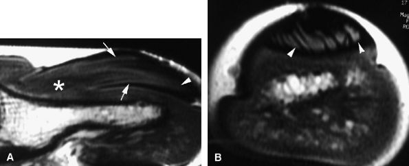
FIGURE 11.28 ● Open wound with partial laceration of the central slip of the extensor tendon. (A) Sagittal post-contrast fat-suppressed T1-weighted and (B) axial STIR images show that the tendon (arrows) is continuous but thickened and demonstrates partial signal abnormalities.
FIGURE 11.29 ● Sagittal post-contrast fat-suppressed T1-weighted image displaying an open wound with complete tear of the central slip of the extensor tendon. There is a tendinous gap (arrows) close to the insertion of the central slip on the base of the proximal phalanx. The tendon retraction is minimal.

P.1864


Closed Injuries
Closed injuries include mallet finger, boutonnière deformity, and injuries of the extensor hood at the MP joint.
Mallet Finger (Zone I). This is the most common closed tendon injury seen in sports. The mechanism is an acute flexion of the DIP joint, usually when the fingertip is struck by or against an object.52 Less commonly, the lesion is produced by a direct blow to the dorsal aspect of the DIP joint or by a hyperextension force applied at this joint.53 The insertion of the terminal band of the extensor tendon on the distal phalanx is injured, with a possible fracture of the base of the phalanx. The patient has pain and swelling of the dorsal aspect of the DIP joint and a lack of active extension. If neglected, mallet finger may evolve into a swan neck deformity.53 Plain films will detect a bony fragment at the base of the phalanx and can be used to assess its size and possible articular extension (Fig. 11.31). Treatment is usually splinting of the joint in extension.52,54 Ultrasonography and MR examination are rarely indicated but may be helpful in assessment of the terminal band of the extensor tendon when radiographs are negative (see Fig. 11.31).
Boutonnière Deformity (Zone III). Injury of the central slip of the extensor tendon at or close to its insertion on the base of the middle phalanx may be responsible for a boutonnière deformity. A blow to the dorsal aspect of the middle phalanx, an acute violent flexion of the PIP joint, and a volar dislocation of the PIP joint are possible mechanisms of injury.52,53
FIGURE 11.30 ● Sagittal post-contrast T1-weighted image showing complications of an open wound of the extensor tendon with adhesions. There is enhancement of peritendinous scar tissue around the tendon (arrows). The extensor tendon shows a loss of tension.
Initial clinical examination shows pain and swelling of the PIP joint, a mild extension lag, and reduced extension strength against resistance. The PIP joint may be maintained in extension by the lateral bands, which are not displaced. If the injury is neglected, the lateral bands may move volarly to the axis of rotation of the PIP joint, causing flexion of the PIP joint and an increased tension on the terminal band of the extensor tendon and subsequent extension of the DIP joint.55 After 1 to 2 weeks the head of the proximal phalanx may displace between the “buttonhole” of the extensor apparatus (boutonnière deformity) (Fig. 11.32).52,53 The usual treatment of acute injuries is splinting of the extended joint. Surgical repair is necessary if reduction is not possible due to soft tissue interposition or in cases of a large displaced bony fragment.56 Entrapment of one condyle of the phalanx head between the

P.1865


central slip and a lateral band of the extensor tendon may occur in cases of additional rotational trauma. Chronic symptomatic lesions require surgical reconstruction.55,57

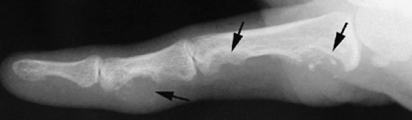
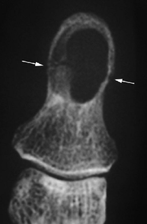
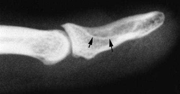
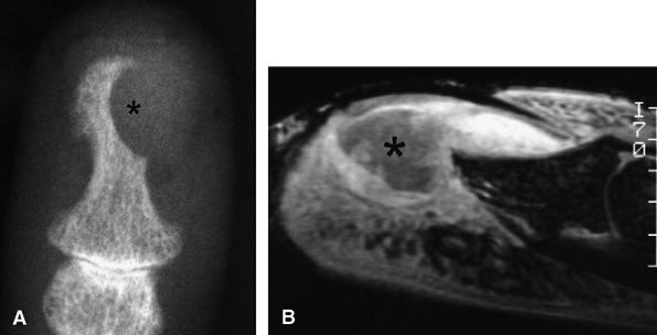
FIGURE 11.31 ● Mallet finger. (A) Fracture avulsion (arrow) of the base of the distal phalanx (lateral view). (B) Sagittal T1-weighted images in a different case showing a tear of the terminal band of the extensor apparatus (arrows) with thickening of soft tissues. There is bone edema (arrowhead) of the base of the distal phalanx without fracture.
Although ultrasound is usually used to assess injuries of the central slip of the extensor tendon,58 evaluation of the other periarticular elements of the PIP joint may be difficult if the joint is stiff. MR accurately depicts both the central slip and any associated lesions of the collateral ligaments and the volar plate, particularly helpful in acute injuries, when the clinical examination may be misleading. In cases of elongation, sagittal MR images show a thickened continuous tendon close to its insertion on the base of the middle phalanx (Fig. 11.33). Edema of the base of the phalanx may also occur. Rupture is suspected if there is a gap with a lack of tendon signal on axial and sagittal images. Usually the central slip is minimally retracted, since there are many connections with the lateral bands of the extensor tendons and with the retinaculum (Fig. 11.34). Axial MR images depict palmar subluxation of the lateral bands in boutonnière deformity (Fig. 11.35).
Sagittal Bands. A tear of a sagittal band of the extensor hood at the level of the MP joint may be responsible for

P.1866


P.1867


subluxation or dislocation of the EDC tendon. The mechanism of injury may be a direct blow with forced flexion and an ulnar deviation of the finger (boxer's knuckle).53,59 The middle and little fingers are most frequently involved, and the radial sagittal band is usually injured with an ulnar subluxation of the tendon (Fig. 11.36). The retinaculum between the two extensor tendons of the little finger may also be injured, and stress imaging depicts a diastasis between these tendons.60 The degree of tendon instability is determined by the extent of sagittal band disruption. A proximal rather than distal tear of the sagittal band contributes to instability (see Fig. 11.36).48 An associated dorsal capsular tear is also possible.60 Patients present with pain and swelling of the dorsal aspect of the MP joint and an inability to completely extend the joint. In neglected injuries the patient reports multiple episodes of pain and swelling with a painful snapping during flexion of the MP joint. Treatment of acute injuries remains controversial, but in general splinting of the extended joint is more often indicated than a simple suture.61 Chronic symptomatic lesions require surgical reconstruction.

FIGURE 11.32 ● Boutonnière deformity. (A) Injury of the central slip (black arrow). The lateral bands (white arrowheads) keep their normal position if the triangular ligament, connecting the two lateral bands, is partially preserved (black arrowhead). (B) There is palmar dislocation of the lateral bands (white arrowheads) if the triangular ligament is torn. Herniation of the PIP joint and boutonnière deformity can be seen.
FIGURE 11.33 ● Sagittal T1-weighted image illustrating elongation of the central slip of the extensor tendon. The thickened continuous tendon (arrows) can be seen close to its insertion on the base of the middle phalanx.
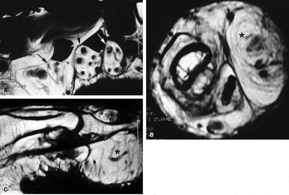
FIGURE 11.34 ● Complete rupture of the central slip of the extensor tendon on sagittal (A) and axial post-enhanced T1-weighted images at the level of the PIP joint space (B) and the distal third of the proximal phalanx (C). There is distal avulsion of the central slip with a tendon gap (arrows) and limited retraction. The proximal end is thickened and shows signal heterogeneity (asterisk).
FIGURE 11.35 ● Boutonnière deformity. Axial T1-weighted image showing a tear of the central slip (asterisk) and palmar subluxation of the lateral bands of the extensor tendon (arrows).
FIGURE 11.36 ● Injury of the radial sagittal band (arrow) with ulnar subluxation of the extensor tendon (arrowhead). The degree of tendon instability is determined by the extent of sagittal band disruption. (A) In a partial tear, a proximal tear rather than a distal tear of the sagittal band contributes to instability. (B) In a complete tear, there is dislocation of the extensor tendon into the intermetacarpal space.
FIGURE 11.37 ● Partial tear of the ulnar sagittal band of the index finger. (A) Axial post-contrast T1-weighted images show focal thickening and blurring of the sagittal band close to the extensor tendon (asterisk). Injury of the radial collateral ligament is also seen (arrows). (B) Axial post-contrast stress T1-weighted image with flexion of the metacarpophalangeal joint demonstrates only a slight subluxation of the tendon (arrow).
Stability of the extensor tendon may be assessed by axial dynamic imaging (ultrasound or MR) with the MP joint in flexion.28,62 Partial tears of a sagittal band appear as a focal thickening and blurring of the sagittal band close to the extensor tendon. Normally the sagittal bands envelop the extensor tendon and the superficial fibers are thinner than the deep fibers.12,63 Peritendinous edema may also be seen. On axial stress images, there is either no or minimal subluxation of the tendon (Fig. 11.37). In complete tears of a sagittal band, the detection of a gap is inconstant, and the diagnosis is suspected

P.1868


when the tendon dislocates on stress images (Figs. 11.38 and Fig. 11.39). Congenital hypoplasia of a sagittal band may be misleading in the middle finger but is not associated with edema and thickening of the soft tissues (see Fig. 11.39).64

FIGURE 11.38 ● Axial stress T1-weighted image of a complete tear of the radial sagittal band. The tear is difficult to detect, but the extensor tendon dislocates in the intermetacarpal space (asterisk).
FIGURE 11.39 ● Complete tear of a sagittal band of the little finger. Two different types of injuries are illustrated. (A) In a tear of the radial sagittal band, the extensor digitorum communis (arrow) and the extensor digiti minimi tendon (arrowhead) dislocate together on the ulnar side (axial stress T1-weighted image). (B) A tear of the retinaculum connecting the two extensor tendons, extensor digiti minimi, and extensor digitorum communis (arrowhead and arrow). Axial stress T1-weighted image highlights a large diastasis between the tendons.
Flexor Tendons
Normal Anatomy
Each finger has two flexor tendons, the FDS tendon and the FDP tendon. The FDS is superficial to the FDP and inserts on the midportion of the middle phalanx. The FDP, in the palm, courses between the two slips of the FDS at the proximal phalanx and becomes volar to the FDS to insert on the volar base of the distal phalanx. Therefore, the FDP tendon courses through the ring aperture of the FDS tendon (chiasm) (Figs. 11.40 and Fig. 11.41).
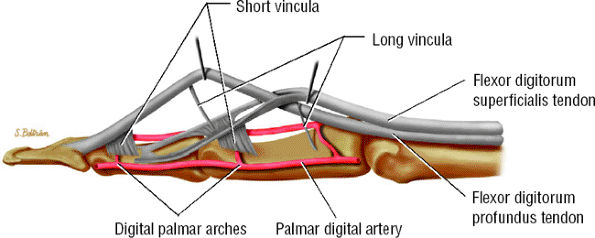
FIGURE 11.40 ● Lateral aspect of the flexor digitorum tendons and their vascular supply.
Both flexor tendons lie in the digital canal, an osteofibrous canal lined by a synovial sheath, which runs from the neck of the metacarpal to the DIP joint. The vinculae join the

P.1869


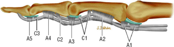
sheath to the tendons and provide the blood supply (see Fig. 11.40).38 The floor of the canal is composed of the volar aspect of the phalanges and the volar plates. The fibrous roof is composed of the five annular pulleys (A1–A5) and the three cruciform pulleys (C1–C3) (Fig. 11.42).65,66,67,68,69

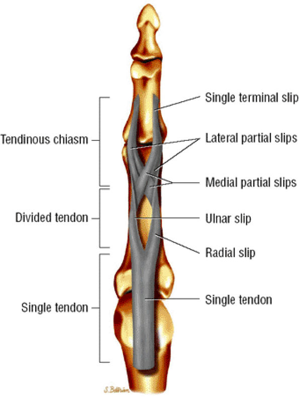
FIGURE 11.41 ● Flexor digitorum superficialis tendon, palmar aspect. A single tendon courses to the proximal third of the proximal phalanx. The tendon then splits into radial and ulnar slips that continue in spirals and diverge to either side. At the distal third of the proximal phalanx, the ulnar and radial slips divide into lateral and medial partial slips. The medial partial slips cross toform the tendon chiasm and to unite with the contralateral lateral partial slip.
FIGURE 11.42 ● Lateral view in extension of the pulley system of the digital flexor tendon sheaths. The flexor tendons undulate along the palmar aspect of the bones of the finger.
TABLE 11.2 ● Zone Classification of Flexor Tendon Injuries
Zone Injury
Zone I: From distal insertion of FDP tendon to the distal insertion of the FDS tendon Isolated laceration of the FDP tendon with loss of active flexion of the DIP joint is uncommon.67
Zone II: So-called no man's land; from the distal insertion of FDS tendon to the distal palmar fold FDP and FDS tendons course together in the digital canal. Injuries are the most common in zone II and the prognosis is worse.68,69 Associated injuries of the palmar proper digital neurovascular bundle are possible.
Zone III: From proximal limit of A1 pulley to distal limit of flexor retinaculum  
Zones IV and V: Carpal tunnel and distal forearm  
The annular pulley system maintains the flexor tendons against the phalanges during flexion of the finger, avoiding a “bowstringing” effect. The cruciform pulleys allow deformation of the tendon sheath during flexion without impingement of the tendon itself.66 There are numerous anatomic variants in the pulley system; the most common configurations are:
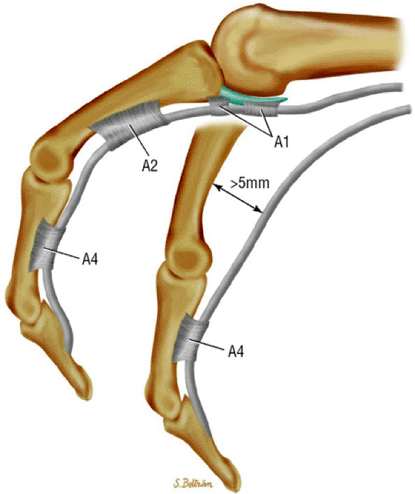
  • An A1 pulley that extends from the volar plate of the MP joint to the base of the proximal phalanx
  • A long A2 pulley that arises from the proximal part of the proximal phalanx and extends to the distal third of the proximal phalanx
  • A small A3 pulley at the level of the PIP joint
  • An A4 pulley at the midpart of the middle phalanx
  • An A5 pulley at the DIP joint (see Fig. 11.42)
The A2 and A4 pulleys are the more constant and thickest annular pulleys.
Flexor Tendon Injuries
As was seen in the extensor apparatus, injuries to the flexor tendons are classified as either open or closed. A zone classification is also used for flexor tendon injuries. This classification uses five zones, according to anatomic location and prognosis (Table 11.2).49 Flexor tendon injuries are less common than injuries of the extensor tendons but are more likely to require MR evaluation. Skin wounds with flexor tendon lacerations are more common than closed injuries.
Open Injuries
Partial lacerations are uncommon and difficult to evaluate clinically. Complete rupture is easier to diagnose, but the degree of proximal retraction may be difficult to assess. The tendon may retract far into the palm, and the palpation of a painful mass does not always match the tendon end. Although the optimal treatment for partial lacerations is controversial,70 complete tears must be repaired surgically.
Several reports demonstrate the effectiveness of MR for the diagnosis of flexor tendon rupture and for assessment of

P.1870


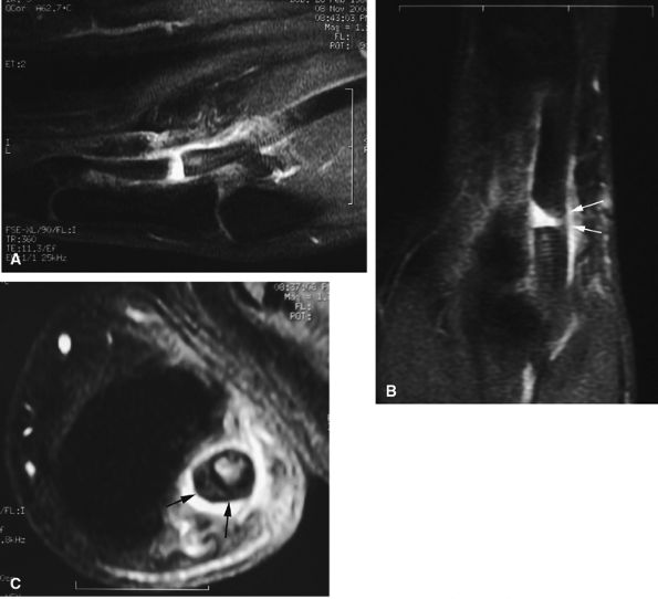
the tendon ends.71,72,73,74 MR findings characteristically include the following:

  • An empty tendon sheath at the rupture area
  • Extensive tenosynovitis, dramatically enhanced after intravenous injection of gadolinium
  • Potentially extensive retraction in complete ruptures (Fig. 11.43) (unlike the situation with extensor tendons, the flexor tendons lack a strong tendon fixation)
  • In acute injuries the gap may be overestimated because the curled retracted tendon remains flexible (Fig. 11.44).
  • Associated pulley injury with some amount of tendon luxation
  • Focal intratendinous signal abnormalities (Fig. 11.45)72 in partial lacerations
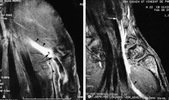
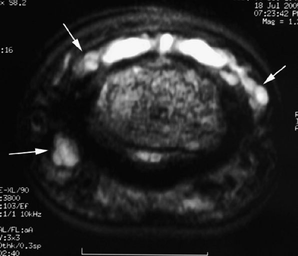
FIGURE 11.43 ● Acute open injury of the flexor pollicis longus tendon. (A) On these coronal post-contrast fat-suppressed T1-weighted images, the distal end of the tendon can be seen at the entry of the digital canal (arrows). (B) The proximal end is seen at the level of the radiocarpal joint (arrows). The tendon gap measures 6 cm. The empty tendon sheath shows significant synovitis (arrowheads in both images).
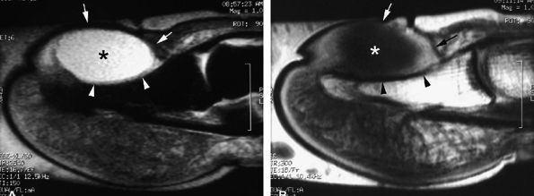
FIGURE 11.44 ● Acute rupture of the flexor digitorum profundus (FDP) tendon of the little finger in zone II. Coronal (A) and axial (B) post-contrast fat-suppressed T1-weighted images show retraction of a flexible proximal end (arrows) wrapping around the FDS tendon (asterisk).
Closed Injuries
Closed injuries of the flexor tendons include “rugby” or “jersey finger” and injuries to the flexor digitorum superficialis tendon.
“Rugby” or “Jersey Finger.”. The most common closed rupture of the flexor tendons is a distal avulsion of the FDP

P.1871


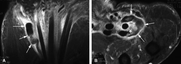
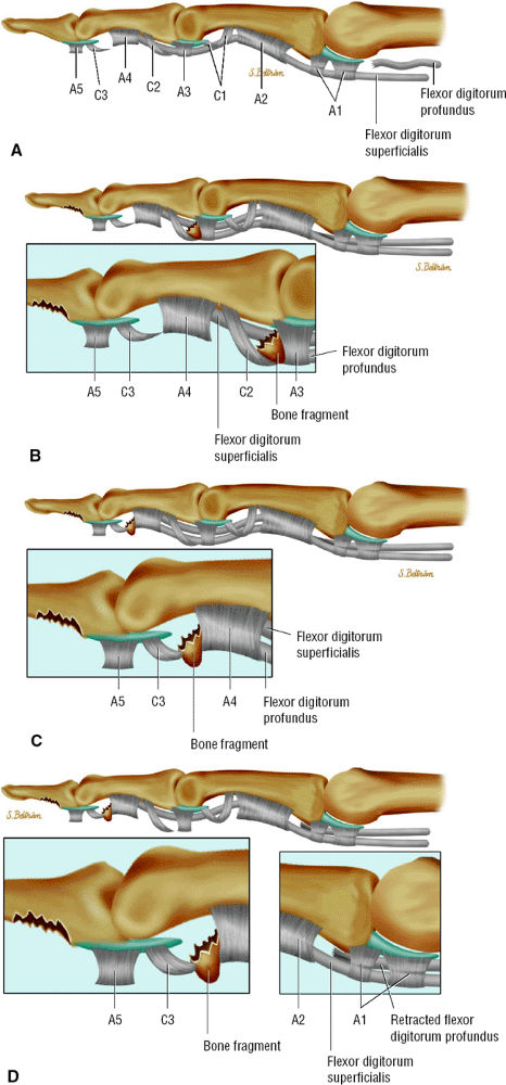
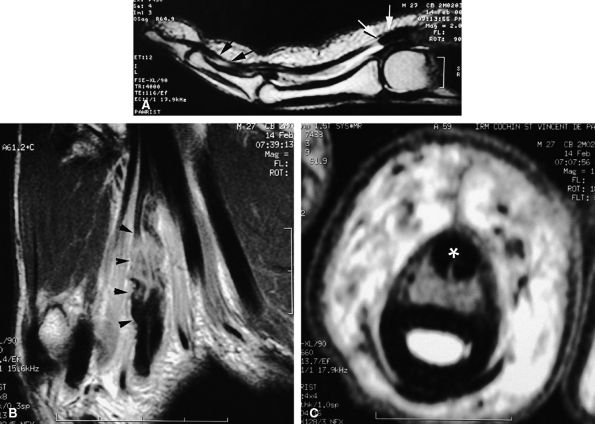
tendon. A sudden hyperextension during active flexion is responsible for this type of avulsion, most often seen in young athletes.75 The ring finger is involved in 80% of cases. This injury is often neglected initially as there is no typical deformity and swelling. Pain may mask a loss of active flexion of the DIP joint. Jersey finger is classified according to the degree of tendon retraction and the presence or absence of a bony fragment (Fig. 11.46):76,77

  • Type I: Retraction of the tendon into the palm
  • Type II: Retraction at the PIP joint. A small bone fleck may avulse and is visible at the PIP level.
  • Type III: Large bony fragment incarcerated in the A4 pulley
  • Type IV: A type III injury with an associated avulsion of the flexor tendon from the bone fragment
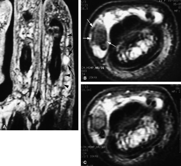
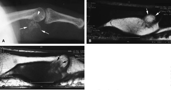
FIGURE 11.45 ● Open partial laceration of the flexor pollicis longus tendon. Sagittal (A), coronal (B), and axial (C) post-enhanced fat-suppressed T1-weighted images showing focal intratendinous high signal with conservation of a thin lateral continuity (arrow). Single orthogonal plane images may be misleading, and a partial tear may be mistaken for a complete tear. This potential pitfall is well demonstrated on the sagittal image (A).
Primary repair of the tendon is usually needed, and trans-osseous reinsertion of the tendon is frequently possible, even with a large gap.78 Ultrasonography can be used to assess the FDP tendon retraction,79 but the anisotropy artifact at the distal insertion of the tendon may be misleading. Sagittal and axial MR images also display tendon retraction. On T2-weighted images the empty digital canal may appear as a low-signal-intensity structure that mimics a flexor tendon but is thinner than a normal tendon (Fig. 11.47). The magic angle phenomenon is often present at the distal insertion of the FDP tendon and may mimic a tendon rupture.80
Flexor Digitorum Superficialis Tendon. Isolated avulsion of the FDS tendon is uncommon and often associated with FDP tendon injury.81 Extension against a contracted flexor muscle is the usual mechanism of injury. The patient cannot flex the involved finger independently at the PIP joint. MR is helpful in the assessment of lesions of both tendons (Fig. 11.48).
FIGURE 11.46 ● Classification of Jersey finger: (A) type I, (B) type II, (C) type III, (D) type IV.
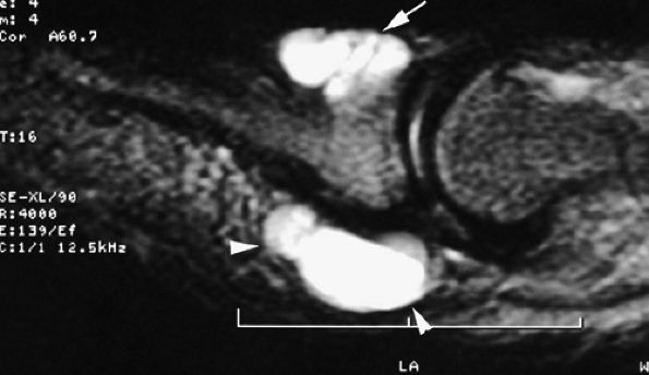
FIGURE 11.47 ● Jersey finger. (A) Sagittal T2-weighted image. (B) Coronal post-contrast T1-weighted images. (C) Axial T1-weighted image. Distal avulsion of the FDP tendon is shown with the proximal end (white arrows) at the metacarpophalangeal joint (type I). The tendon is wavy in the palm (arrowheads). The empty digital canal (in C) may mimic a remnant tendon, but the FDS tendon (asterisk) is alone in the canal.
FIGURE 11.48 ● Axial post-contrast fat-suppressed T1-weighted image showing isolated laceration of the flexor digitorum superficialis (FDS) tendon. Irregularities and signal abnormalities of the radial band of the FDS can be seen close to its insertion (arrow).
FIGURE 11.49 ● Healing process in a flexor digitorum profundus (FDP) tendon suture. Sagittal (A) and axial (B) T1-weighted images show surface irregularities of the suture area (arrows). Most of the surface of the tendon callus demonstrates low signal intensity (arrowheads).

P.1872


P.1873


P.1874


Postoperative Complications
Normal Healing
After surgical repair, the healing process restores the tendon surface.82 Residual tendon surface irregularities are possible and visible on sagittal MR images (Fig. 11.49). The tendon ends may be highlighted by artifacts from suture placement. A solid callus is the result of extrinsic and intrinsic healing.83,84 Extrinsic healing is produced when granulation tissue from the peritendinous tissues invades the repair site. Therefore, adhesions may be found on the damaged tendon surface. The tendon itself has an endogenous ability for repair (intrinsic healing). There is no real regeneration, although there is a progressive alignment of the collagen fibers according to the gliding axis of the tendon and a progressive decrease in tissue cellularity, indicating maturation of the healing.85,86 The callus may appear slightly heterogeneous on MR images. On axial images, round areas of very low signal are mixed with areas of intermediate signal intensity in the callus and correspond respectively to collagen fibers and immature tissue healing (see Fig. 11.49). Healing, with consolidation of collagen, takes at least 6 weeks, and there is a risk of rupture during this period. Of the numerous factors influencing maturation, rehabilitation is one of the most important.
New Tendon or Graft Rupture
Clinical examination is usually not sufficient to evaluate an unsatisfactory tendon repair, since it is necessary to differentiate among adhesion, elongation of the callus, and a new tendon rupture.87 Ultrasound is usually used to evaluate the quality and the length of the callus. It also allows dynamic scanning of flexor and extensor tendons in real time, particularly useful in the detection of adhesions of flexor tendons with a disturbed gliding mechanism.88,89 MR examination of the flexor and extensor digitorum tendons may be helpful in the selection of the most appropriate therapy. A new tendon rupture is easily depicted on MR images, and the length of the gap can be measured. With MR imaging it is also possible to assess associated scar tissue and the state of the annular pulleys (Fig. 11.50). A secondary repair with lengthening by tenotomy at the musculotendinous junction is possible if the gap is less than 3 cm and the digital canal is normal.90 A satisfactory gliding surface with a free digital canal and pulleys of good quality are necessary for grafting to be a success.91 MR imaging can reveal a graft rupture, usually at the proximal juncture, in a semiemergent situation (Fig. 11.51).45 A staged flexor tendon reconstruction is necessary when MR shows a badly scarred digital canal and deficient annular pulleys with a large tendon gap.92
Elongation of Callus
Elongation of a tendon callus is very common and can almost be considered a physiologic process if it does not exceed 5 mm.93,94 However, when the callus is longer than 3 mm, gliding resistance increases and catching at a pulley edge is possible.95 In some cases of unsatisfactory clinical function postoperatively, MR demonstrated calluses exceeding 10 mm, with poor maturation (predominant intermediate signal) (Fig. 11.52). When elongation

P.1875


P.1876


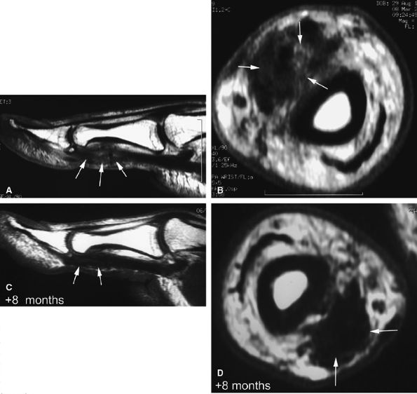
exceeds 10 mm, reorganization of the tendon is not possible and reoperation (tendon grafting) is often the preferred option.93

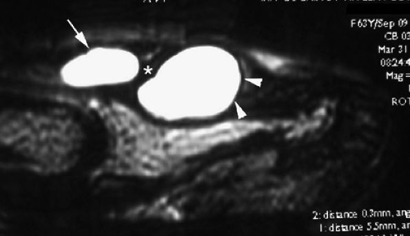
FIGURE 11.50 ● Acute rupture of the flexor digitorum profundus (FDP) tendon in zone II. Sagittal post-contrast fat-suppressed T1-weighted image shows the gap, which measured 3 cm (arrows). Note the slight deficiency of the A2 pulley (arrowheads).
FIGURE 11.51 ● Rupture of a tendon graft of the flexor tendons of the index finger in zone III. Coronal post-contrast fat-suppressed T1-weighted image shows the tendon graft proximally retracted in the palm (arrow).
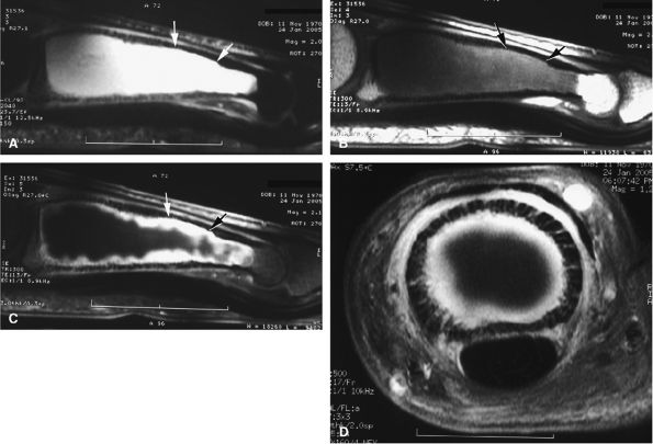
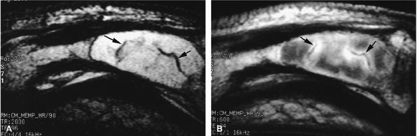
FIGURE 11.52 ● Elongation of a tendon callus of the flexor pollicis longus. Sagittal (A) and axial (B) post-contrast T1-weighted images show a thickened callus 1 cm in length with predominant scar tissue (arrows). Eight months later, sagittal (C) and axial (D) post-contrast T1-weighted images demonstrate the maturation process with thinning of the callus and predominant low-signal-intensity mature tissue (arrows).
Adhesions
Despite the best efforts at flexor tendon repair, adhesions are a common complication, occurring in nearly half of the cases.45 The value of tenolysis, which involves freeing adhesions and reconstructing pulleys, is questionable after the failure of several months of vigorous rehabilitation, and resection of the FDS may be necessary to free the digital canal. A staged reconstruction is preferable if 30% or more of the tendon width has been lost.96 MR examination is useful in assessing the degree of tendon loss (Fig. 11.53). Tenolysis should be avoided for at least 6 months due to the risk of secondary rupture (devascularization and mobilization).97
Pulley Injuries
Pulleys are vulnerable to four main pathologies:
  • Trigger finger, congenital or progressive
  • Tenosynovial ganglions
  • Lesions of the flexor tendon sheath associated with traumatic lacerations or surgical repairs
  • Ruptures due to overuse or stress (such as occurs during some sports activities, like rock climbing)98,99
FIGURE 11.53 ● Postoperative adhesions in the digital canal. Axial post-contrast T1-weighted image shows adhesions between the disorganized FDP and FDS tendons. Note the palmar dislocation of the flexor tendons (arrows) due to deficiency of A2 pulley.
Annular pulley ruptures may occur during powerful flexions of the fingers with MP joint extension, PIP joint flexion, and DIP joint extension. The distal end of the A2 pulley is first partially torn, with progressive extension to complete rupture and involvement of the A3, A4, and, rarely, A1 pulleys (Fig. 11.54).100 Pulley ruptures usually involve the long fingers, particularly the A2 pulley of the fourth finger of the nondominant hand, but some rare ruptures of the thumb annular pulleys have also been reported.101,102
In acute injuries, pain and swelling may blur the depiction of flexor tendon bowstringing. Neglected tears of the annular pulleys may be complicated by scar tissue and stiffness of the PIP joint.103 An early and accurate diagnosis can prevent these complications. The choice between a conservative or surgical approach to treatment depends on the age of the patient, the degree of the pulley tear, and the number of injured pulleys.104
Ultrasonography and CT and MR imaging are all accurate for assessment of injuries of the pulley system. A dynamic study with forced flexion increases the sensitivity and is easier to perform with ultrasonography or CT.105,106,107,108 Ultrasound scans provide excellent visualization of the finger pulleys, except for the A5 annular pulley and the C2 and C3 cruciform pulleys.109 MR also provides accurate assessment of annular pulley injuries. Although sagittal

P.1877


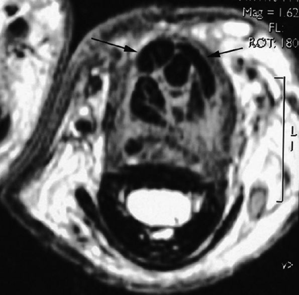
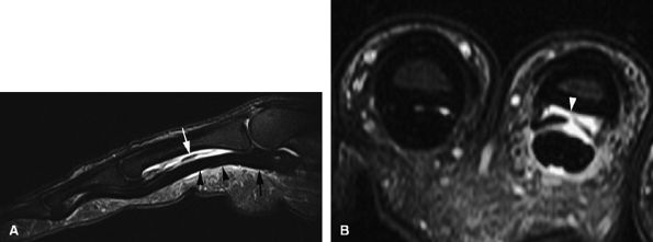
and axial MR images directly depict the tear as a thickening and a defect of the pulley (Fig. 11.55), sagittal images, which display the indirect sign of bowstringing, are more sensitive, particularly with imaging performed in forced flexion (Fig. 11.56).

FIGURE 11.54 ● Injury of A1 and A2 annular pulleys with complete tear. There is bowstringing of the flexor tendons during flexion.
FIGURE 11.55 ● Rupture of A2 pulley of the fourth finger. Sagittal (A) and axial (B) post-contrast T1-weighted images show the tear of the A2 pulley on the midline (black arrowheads) with a palmar dislocation of the flexor tendon. The pulley (white arrow and arrowhead) is now deeply located beneath the flexor tendons. Note the integrity of the A1 pulley (black arrow).
MR images also display and allow measurement of the increased distance between the flexor tendon and the phalanx.110,111 During forced flexion, this gap increases proportionally to the number of disrupted pulleys. The gap is 2 to 5 mm in isolated complete tears and 5 to 8 mm in simultaneous complete tears. A partial tear of the A2 pulley is suspected when bowstringing does not extend proximally beyond the base of the proximal phalanx. Measurement has no significance in partial tears.105
FIGURE 11.56 ● Bowstringing of the flexor tendons. Sagittal stress post-contrast T1-weighted image with forced flexion shows palmar dislocation of the flexor tendons (arrows) due to rupture of the A2 and A3 pulleys.
FIGURE 11.57 ● Trigger finger. (A) Sagittal T1-weighted image with a normal A1 pulley (arrow). Sagittal (B) and axial (C) fat-suppressed post-contrast T1-weighted images showing ulnar nodular inflammatory thickeningof the A1 pulley (arrows) associated with mild flexor tendinosis (asterisk).

P.1878


Trigger Finger
Trigger finger is a common stenosing tenosynovitis of the flexor tendons. Primary stenosing tenosynovitis is usually idiopathic and results from chondroid metaplasia of the A1 pulley. It occurs more frequently in middle-aged women. Secondary stenosing tenosynovitis of the fingers may occur in rheumatoid arthritis, diabetes mellitus, gout, and other connective tissue disorders.
The clinical diagnosis of trigger finger is usually obvious.112 In recurrent cases, however, it may be difficult to assess the anatomic lesions accurately without imaging. Ultrasonography and MR imaging both depict diffuse or nodular inflammatory thickening of the A1 pulley. On sagittal images, associated focal compression of the underlying flexor tendons may be seen, as well as a more distal nodular tendonitis or a tenosynovitis (Figs. 11.57 and Fig. 11.58). Imaging is also helpful in guiding placement of steroid injections in recurrent cases113 and in depicting uncommon etiologies, particularly an old partial laceration of the FDS tendon or an intertendinous connection between the FDS and the FDP tendons in the palmar region (Fig. 11.59).114,115
FIGURE 11.58 ● Trigger finger. Sagittal (A) and axial (B) post-contrast T1-weighted images show a diffuse inflammatory thickening of the A1 pulley (arrows) and a distal nodular tendinosis (asterisk).
FIGURE 11.59 ● Trigger finger. Axial post-contrast fat-suppressed T1-weighted image showing partial laceration of the flexor digitorum superficialis (FDS) tendon (arrow) with inflammatory reaction.

P.1879


Vascular Trauma
Posttraumatic Arteriovenous Fistulas
Posttraumatic arteriovenous fistulas (AVFs) are acquired high-flow lesions.116 Chronic longstanding traumatic AVF may simulate and be misdiagnosed as an arteriovenous malformation (AVM). They have been extensively described at the digital extremities and in the palm of the hand.117 Histologic features similar to hemangioendothelioma have been reported within posttraumatic AVF. Flow void artifacts on T1- and T2-weighted images indicate a high-flow lesion but are not very sensitive. Dynamic 3D gradient-echo sequences after intravenous injection of gadolinium appear to be more sensitive (Fig. 11.60).118
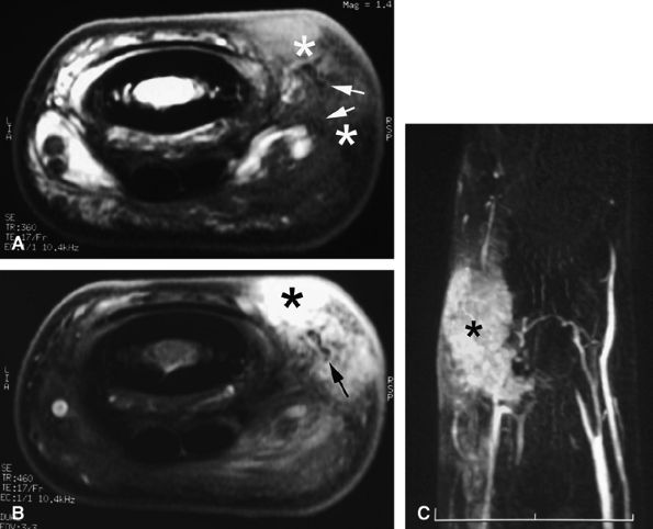
FIGURE 11.60 ● Posttraumatic arteriovenous fistulas. Axial post-contrast 3D gradient-echo image shows peripheral enhancement (arrows) and a central flow void (asterisk) due to high velocity.
Hypothenar Hammer Syndrome
The hypothenar hammer syndrome involves the terminal portion of the ulnar artery. The superficial branch of the ulnar artery, which becomes the superficial palmar arch, is exposed to injury where it emerges from Guyon's canal and runs superficially across the hypothenar musculature for 2 cm. Clinical symptoms appear more distally, due to arterial emboli in the second through fifth digits.116,119
Thrombosis of the common digital artery may be visualized on ultrasound, but a detailed preoperative evaluation includes digital subtraction angiography, multislice spiral CT angiography, or magnetic resonance angiography (MRA).120 Emboli may be seen in as many as 50% of cases at MRA. The correct diagnosis is indicated by highlighting of the initial lesion of the ulnar artery at the level of the hamate (Fig. 11.61).121,122,123
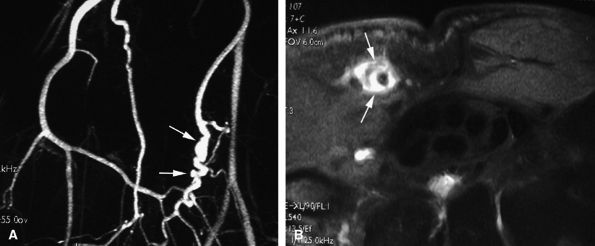
FIGURE 11.61 ● Hypothenar hammer syndrome. (A) MR angiography shows a typical corkscrew pattern (arrows) of the ulnar artery extending to the deep palmar arterial arch. (B) Axial post-contrast fat-suppressed T1-weighted image depicting inflammatory thickening of the ulnar artery walls (arrows).
FIGURE 11.62 ● Palmar proper digital nerve neuroma. Axial T1-weighted image displaying the enlarged medial palmar proper digital nerve (arrows) with hypertrophic nerve bundles. Note the normal contralateral nerve (arrowhead).

P.1880


Nerve Trauma
Neuromas are pseudotumors of the digital nerves that develop after injury or repetitive microtrauma. Of the many procedures for treating painful neuromas, resection and proximal translocation or skin flaps are the most common.124 On MR examination, a small, well-circumscribed nodule in the finger is displayed. A diagnosis of neuroma must be considered when the nodule is located on the course of a common digital nerve or a proper digital nerve. The lesion demonstrates low to intermediate signal intensity on T1- and T2-weighted images (Fig. 11.62). Gadolinium injection produces only faint or no enhancement, although enhancement is increased by fat suppression.
Soft Tissue Pseudotumors and Tumors
The pseudotumors most often involving the fingers are ganglions and Dupuytren's contracture. The most common benign tumors are tenosynovial giant cell tumors and vascular malformations. Malignant tumors or metastatic lesions of the fingers are unusual.125 In the periungual region, glomus tumors, pseudomucoid cysts, and epidermoid cysts may be found.126 Radiographs and ultrasonography are often the first imaging modalities used and can depict underlying bone or joint disease such as intralesional calcifications, scalloping, or a cystic or vascular tumor. Ultrasonography, however, may be limited to characterization of a solid mass in the finger. MR imaging is likely to provide more information about a specific mass, especially important in preoperative evaluation.
Pseudotumors
Ganglion Cysts and Tenosynovitis
Ganglion cysts are cystic lesions filled with a thick gelatinous fluid. Their cause is unknown, although trauma has been postulated as an inciting factor. They occur more commonly in women (female to male ratio of 2.6:1), and most patients are in their third to fifth decade. The middle finger is most commonly affected, and 69% of the ganglions are located at the weak point between the A1 and A2 pulleys (Fig. 11.63).99 More distal locations at the PIP and DIP joints are less common and may be related to osteoarthritis in patients older than 65 years of age.127, 128,129 Rarely an ossified ganglion is depicted on plain films.130 Treatment is percutaneous punctures or surgery, but recurrences are common (89%).
Imaging may be useful in preoperative planning.131 On ultrasound scans the lesion appears as one or several anechoic masses with an associated tenosynovitis.132 The depiction of a peduncle may be more difficult, as is visualization of underlying joint disease. MR images show a well-delineated homogeneous mass with low to intermediate signal on T1-weighted images, depending on protein concentration. On T2-weighted images the cyst displays very high signal and common intralesional septa are better depicted. After intravenous injection of gadolinium, there is a thin and regular enhancement of the peripheral wall and septa (Figs. 11.64 and Fig. 11.65). Hemorrhage may change the appearance of the cyst, which will display high signal intensity on T1-weighted images and low signal intensity on T2-weighted images. Fluid–fluid levels are exceptional. Sometimes T2-weighted images display a thin and irregular pedicle communicating with an underlying PIP or DIP joint.
Rarely, extensions of ganglions have been found in theextensor tendon at the level of the metacarpals.133,134,135 Thecyst may be large and hard enough to block sliding of the extensor tendon beneath the extensor retinaculum.136 The EDC and EIP tendons are more commonly involved. Axial T2-weighted

P.1881


P.1882


images show intratendinous extension of the cyst with peripherally displaced thin tendinous walls (Fig. 11.66). Tenosynovitis is commonly associated at the level of the wrist. A painful cyst may be due to extrinsic nerve compression or, rarely, intraneural infiltration of a proper digital nerve (Fig. 11.67).137 Intraosseous ganglions in the phalanx have also been reported.138

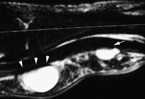
FIGURE 11.63 ● Palmar ganglia of the A1 and A2 pulleys. Sagittal STIR image depicts the proximal ganglion close to the A1 pulley (arrowheads) and the distal ganglion against the distal part of A2 pulley (arrow).
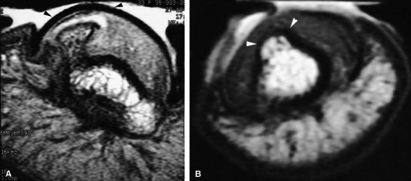
FIGURE 11.64 ● Dorsal ganglion at the proximal phalanx on (A) an axial T2-weighted image, (B) a T1-weighted image before contrast administration and (C) a T1-weighted fat-suppressed image after injection of gadolinium. The ganglion (asterisk) shows a homogeneous high signal on the T2-weighted image and low signal on T1-weighted images. There is no peripheral enhancement.
FIGURE 11.65 ● Inflammatory dorsal ganglion. Axial post-contrast T1-weighted image shows strong enhancement of the peripheral walls of the ganglion (arrows).
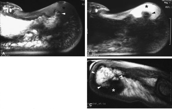
FIGURE 11.66 ● Intratendinous ganglion. Sagittal (A) and axial (B) T2-weighted images and an axial post-contrast fat-suppressed T1-weighted image (C) show a ganglion (asterisks) infiltrating the central part of the extensor digitorum communis tendon of the middle finger. The tendon wall is displaced peripherally (arrows).
Tenosynovial Inflammation
Granulomatous inflammation of the synovium may be encountered in a variety of diseases, such as infection with Mycobacterium tuberculosis or atypical mycobacteria, certain fungal infections, or Brucella infections. Inflammatory disorders, such as sarcoidosis, crystal-associated arthritis, gout, or foreign body reactions, may also present as granulomas.
Tuberculosis and Atypical Mycobacteria
Tuberculous tenosynovitis is a rare manifestation of musculoskeletal tuberculosis. Nevertheless, TB is reported to be the most common cause of chronic infections of the tendon sheaths of the hand.139 Almost any long tendon may be affected, although the wrist is a more common site than the fingers. MR examination reveals tendon sheath fluid and thickened synovium. Low-signal-intensity areas on T2-weighted images may represent tissue debris, caseous material, fibrosis, or calcifications.125 The tendon may be infiltrated by caseous tissue and appears thickened or partially torn (Fig. 11.68).
Chronic cutaneous lesions, tenosynovitis, septic arthritis, and osteomyelitis may be due to infection with atypical mycobacterium. Mycobacterium marinum is the most likely to cause skin infection. The diagnosis may be challenging since soft tissue infections associated with chronic skin ulceration many be seen in a variety of infectious diseases (e.g., TB, tertiary syphilis, blastomycosis, botryomycosis) as well in malignant processes. Patients exposed to aquatic activities are at particular risk for M. marinum infections (“fish tank finger”).140,141 The mean time from injury to diagnosis is more than 5 months.142
Hypertrophic synovium may be seen on MR examination, and although there is no specific pattern, synovial changes may be striking, in contrast to the chronic painless clinical manifestation.143,144,145 There may also be rice bodies within the affected tendon sheath, mimicking synovial chondromatosis.146 Associated soft tissue abscesses may point to the possibility of atypical mycobacterial infection in the differential diagnosis.145
FIGURE 11.67 ● Intraneural ganglion. Axial (A and B) and coronal (C) T1-weighted images of a ganglion (asterisk) infiltrating the medial proper digital nerve (arrows).
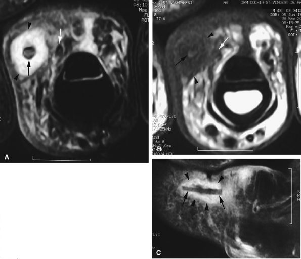
FIGURE 11.68 ● Tuberculous tenosynovitis. Sagittal (A) and axial (B) post-contrast fat-suppressed T1-weighted images show strong enhancement of the tenosynovitis in the digital canal. The flexor tendons are thickened and infiltrated by caseous necrosis (arrow).

P.1883


P.1884


Sarcoidosis
Sarcoidosis is a chronic systemic disease characterized by multiple noncaseating granulomatous nodules. Sarcoidosis of the phalanx is relatively rare and is usually associated with severe systemic disease. Affected phalanges demonstrate bony cystic lesions filled with a granulomatous proliferation.147,148 Multiple fractures may occur in the weakened phalanges.149 Sarcoid arthropathy of small joints is often symmetrical and is more common than sarcoid tenosynovitis and subcutaneous sarcoidosis.150 The flexor tendons are mostly involved, resulting in flexion contractures.151
Gadolinium contrast-enhanced MR imaging demonstrates the articular synovitis and tenosynovial nodules, as well as bone destruction (Fig. 11.69). Tendon rupture in longstanding sarcoid tenosynovitis has also been described.152,153
Gout
Gout is a metabolic disorder characterized by overproduction of uric acid. Monosodium urate crystals are deposited in periarticular, subcutaneous, synovial, tendinous, and articular tissues. The small joints of the hand are occasionally involved, especially in patients who developed the disease at a younger age. Tophi, palpable masses composed of urate crystals or amorphous urate, are commonly seen as hard nodules around the fingers. The diagnosis of gout is usually clinical. Signs and symptoms, biochemical data, and radiographs are sufficient to make a diagnosis, and MR imaging is not indicated. On occasion, however, unusual forms of gout, with inflamed tophi and occult articular disease, may be mistaken for infection or neoplasm. For instance, granulomatous tenosynovitis due to gouty tophaceous deposits may mimic tuberculous tenosynovitis.154 Gout should be considered in the differential diagnosis of granulomatous tenosynovitis, especially when acid-fast stains and culture are negative for mycobacteria.
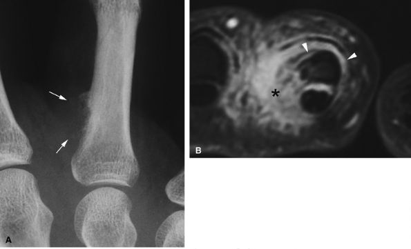
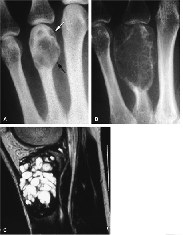
FIGURE 11.69 ● Sarcoidosis with osseous involvement (arrowheads). PA view radiograph (A) showing polycystic osseous involvement of the fingers. A sagittal 3D post-contrast gradient-echo image (B) and an axial post-contrast T1-weighted image (C) depict polysynovitis with joint synovitis (asterisks) and polynodular tenosynovitis (arrows).
On MR examination, tophi display intermediate signal intensity on T1-weighted images, variable signal intensity on T2-weighted images, and strong post-contrast enhancement.155 Occult subclinical tophi may also be detected on MR examination.156

P.1885


Chondromatosis of the Tendon Sheath
Tenosynovial chondromatosis is due to cartilaginous metaplasia of the synovium of a tendon sheath. Cartilaginous bodies are first produced in the synovium and later are released into the joint or the tendon sheath. At this point they may be ossified,157 and patients present with a swollen and stiff finger.
Plain films may be negative early in the process, or they may show calcified nodules.158 MR imaging depicts a lobulated mass with signal intensity similar to cartilage. Intralesional signal voids are due to calcifications. The synovium is thickened and enhances strongly after gadolinium administration (Fig. 11.70).
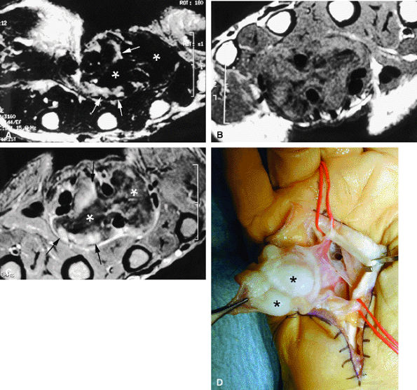
FIGURE 11.70 ● Chondromatosis of the sheath of the flexor tendons on (A) an axial fast spin-echo T2-weighted image and T1-weighted images before (B) and after (C) injection of gadolinium with fat suppression. There is enlargement of the tendon sheaths of the third and fourth fingers with synovitis (arrows) and cartilage signal characteristics (asterisks). (D) Surgical exposure indicating white cartilage nodules (asterisks).

P.1886


Foreign Body Reaction
Penetrating trauma of the finger is common, and foreign bodies are usually promptly removed by the patient or a physician. Sometimes, however, the initial trauma is overlooked or the foreign body cannot be removed, resulting in a foreign body granuloma. The patient has a painful mass on the finger. Radiopaque foreign bodies can be detected on plain films, and most others can be seen on ultrasound.159 MR imaging can also be used to display foreign bodies and granulomatous reaction. On T2-weighted images, longstanding foreign bodies (e.g., glass, wood splinter) are seen as low-signal areas surrounded by a high-signal granuloma. Post-contrast studies show thick peripheral enhancement (Fig. 11.71).160
Dupuytren's Contracture
Dupuytren's contracture, a superficial palmar fibromatosis, is common, occurring in 1% to 2% of the general population. The palmar aponeurosis of the hand is the main target, but more distal extension to the PIP joint may also be seen. Initially a small subcutaneous nodule is palpated in the palm at the level of the distal palmar crease. Longitudinal cords appear later, with collagen fibers oriented parallel and superficial to the flexor tendons. The overlying skin thickens and retracts, resulting in a flexion contracture. The annular (ring) finger is commonly involved.125
FIGURE 11.71 ● Foreign body granuloma on an axial STIR image (A), an axial T1-weighted image (B), and a sagittal post-contrast fat-suppressed T1-weighted image (C). A wood splinter (black arrows) with a peripheral enhanced granuloma (arrowheads) can be seen. The proper digital neurovascular bundle is deeply displaced (white arrows).
T1- and T2-weighted MR images depict low-signal cord-like structures arising from the palmar aponeurosis. The distal expansion appears as subcutaneous thin strands or small nodules. These nodules are depicted in nearly 60% of patients and present different signal characteristics and variable gadolinium enhancement depending on the degree of cellularity (Fig. 11.72).161 It is not uncommon to find several intralesional low-signal dots. Nodules with lower signal intensity on T2-weighted images correlate with lesions with less cellularity. These lesions tend to recur less frequently (18%) than the more cellular lesions (70%).
FIGURE 11.72 ● Dupuytren's contracture. Axial (A) and sagittal (B) T1-weighted images and an axial post-contrast fat-suppressed T1-weighted image (C) show a heterogeneous nodule of the palmar aponeurosis (arrowheads) and subcutaneous small nodules with high cellularity (strong enhancement) (arrows) along the little finger. (D) In a separate case, axial T1-weighted images show a large strand with low signal and finger contracture (arrows).

P.1887


Benign Tumors
Tenosynovial Giant Cell Tumors
Tenosynovial giant cell tumors, also called giant cell tumor of the tendon sheath or localized nodular tenosynovitis, originate from the tendon sheaths and share histopathologic features with pigmented villonodular synovitis.162,163 Tenosynovial giant cell tumors of the fingers are not uncommon; in fact, they are the second most common tumors of the soft tissues in the hand.164,165 These tumors are primarily found in adults 30 to 50 years of age.166,167 Most often the tumor is seen as a solitary nodule close to a tendon sheath on the palmar aspect of the first three fingers. Clinically the patient reports an asymptomatic, slowly enlarging mass attached to deep structures (tendon sheath, capsule). The lesion may be painful when neurovascular elements are compressed. Surgery is mandatory, and local recurrences may occur in as many as 30% of cases.162
Imaging evaluation of tenosynovial giant cell tumors includes plain films, ultrasound, and MR imaging. Plain films may depict a pressure erosion and less commonly a periosteal reaction (Fig. 11.73). There are no calcifications, as would be

P.1888


seen with synovial sarcomas. Bone and joint invasion is possible.168 Ultrasonography shows a nonspecific solid mass with a variable color Doppler signal. MR images are specific, depicting a well-defined mass with hemosiderin deposits. Typical signal void artifacts are seen on all sequences, particularly on gradient-echo images, and a more heterogeneous and predominantly low signal is found on T2-weighted images.162,166,169 The lesion typically enhances after intravenous injection of gadolinium (Fig. 11.74). The tendon sheath of the flexor digitorum tendons is usually partially or totally enveloped; the extensor tendons are less commonly involved. Some lesions may be more aggressive, and diffuse lesions are seen in multiple locations with invasion of both the flexor and extensor tendons (Fig. 11.75).170

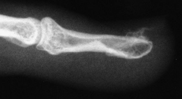
FIGURE 11.73 ● Giant cell tumor of the tendon sheath. Lateral view radiograph shows a large mass of the palmar soft tissue (asterisk) and bone pressure erosion (arrows).
FIGURE 11.74 ● Giant cell tumor of the tendon sheath. Sagittal T2-weighted image (A) and post-contrast T1-weighted image (B) show a palmar mass (arrows) close to the sheath of the flexor tendons with predominant low signal (arrowhead) on the T2-weighted image and strong enhancement following contrast administration.
Fibromas of the tendon sheath demonstrate similar signal characteristics but are much less common in the fingers.
FIGURE 11.75 ● Aggressive giant cell tumor of the tendon sheath. Sagittal post-contrast 3D gradient-echo (A) and axial T1-weighted (B) images depicting a multinodular tumor invading the flexor and extensor tendons as well as the head of the phalanx (arrow).
Vascular Malformations
Vascular manifestations of a variety of diseases may involve the fingers. A fluctuant soft tissue mass is a common presentation of a vascular malformation. Plain radiographs are useful in the search for a periosteal reaction or phlebolith,171 and noninvasive vascular assessment can be performed with color Doppler imaging and CT or MRA. Occasionally, digital subtraction angiography (DSA) may be necessary for preoperative planning and ultimately for therapeutic purposes. DSA also allows imaging of the entire upper extremity vascular tree from its origin at the aortic arch to the digits. Doppler imaging and MRA may be useful in following the patient's response to therapy.
There remains widespread confusion regarding properterminology of vascular masses of the fingers. The term

P.1889


“hemangioma” is often used as a generic term, although it represents a well-defined and rather unusual entity. Hemangiomas result from endothelial hyperplasia and consist of lobules of microcapillaries. They are absent or discrete at birth and grow rapidly in successive phases of proliferation and regression. Vascular malformations do not exhibit endothelial abnormalities; they are present at birth and their growth follows that of the child; and they never regress. In 1996, the International Society for the Study of Vascular Anomalies (ISSVA) classification was proposed by Enjolras and Mulliken, based on the initial classification of Mulliken and Glowacki proposed in 1982 (Table 11.3).172 In this classification low-flow malformations include venous, lymphatic, and capillary malformations. High-flow malformations are represented by AVMs and AVFs.173 The distinguishing features of infantile hemangioma and vascular malformations are presented in Table 11.4.

TABLE 11.3 ● ISSVA Classification of Intramuscular Vascular Anomalies
Tumors Malformations
Intramuscular hemangioma adolescent, young adult Low-flow: venous, lymphatic, venous-lymphatic malformations
  High-flow: arteriovenous malformations (AVMs) and congenital arteriovenous fistulas (AVF)
Superficial cutaneous vascular lesions of childhood are easily recognized clinically; usually no imaging is necessary. Deeper vascular lesions may be discovered in adolescents and young adults, sometimes after trauma. They occur much less frequently and have no sex predilection. Although these lesions are present at birth and grow with the child, they may not be discovered until much later. They may be quiescent and cause no symptoms, but once they become symptomatic they rarely regress.
Venous Malformations
Venous malformations are the most common type of vascular malformation. They are usually discovered in children, teenagers, or young adults, and patients may seek medical attention because of localized pain, soft tissue swelling, or more rarely decreased function. Pain is related to effort or occurs in the morning after waking up. Cold and rainy weather appears to exacerbate the pain, whereas warm weather tends to alleviate symptoms.174 Palpation reveals a tender mass under normal or bluish skin.175 The mass is not pulsatile and there is no thrill. Venous malformations contain multiple abnormal, irregular veins dissecting soft tissues. The walls of the veins exhibit a localized deficit of α-actin-positive smooth muscle cells.
Imaging evaluation of venous malformations includesplain films, ultrasonography, and MR examination. Phleboliths, small round calcific densities that represent calcium aggregates within thrombosed venous lakes (Fig. 11.76), may be seen on plain films and are a useful finding in the diagnosis of venous malformation. They occur less frequently in intramuscular lesions than in superficial ones.
Color Doppler imaging is an essential tool in the diagnostic workup of venous malformations. Ultrasound diagnosis is not always straightforward, however, although it is somewhat easier in cases of large malformations. The usual finding is a hypoechoic serpiginous compressible mass with a monophasic Doppler signal. Precise contours may be difficult to establish on ultrasound scans. The absence of Doppler signal is noted in 16% of venous malformations and should raise the suspicion of thrombosis of the lesion.176 Phleboliths appear as hyperechoic foci with posterior acoustic shadowing. With compression, the mass decreases in size and there is disappearance of some anechoic areas representing dilated veins.27 Follow-up color Doppler imaging can detect persistent thrombosis of low-flow malformations.116
TABLE 11.4 ● Distinguishing Features of Infantile Hemangioma and Vascular Malformation
Infantile Hemangioma Vascular Malformations
Endothelial proliferation Anomalous morphogenesis of vessels with ectasia, changes in blood pressure and flow, development of collaterals, shunt, and sometimes hormone-dependent changes. No endothelial proliferation.
Absent or discrete at birth Present at birth
Rapid growth within a few months Growth rate similar to that of the child
Involution during childhood (with the exception of intramuscular hemangiomas) No spontaneous regression
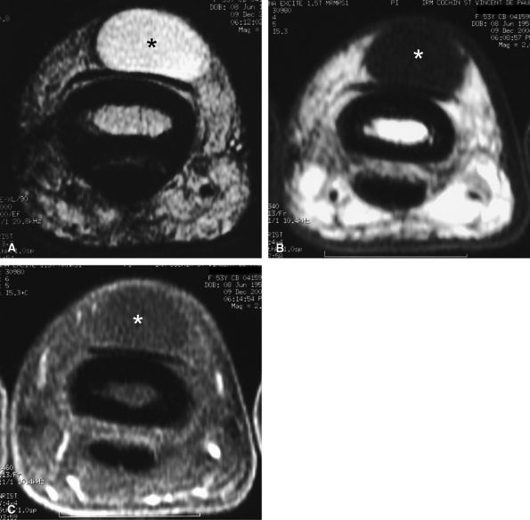
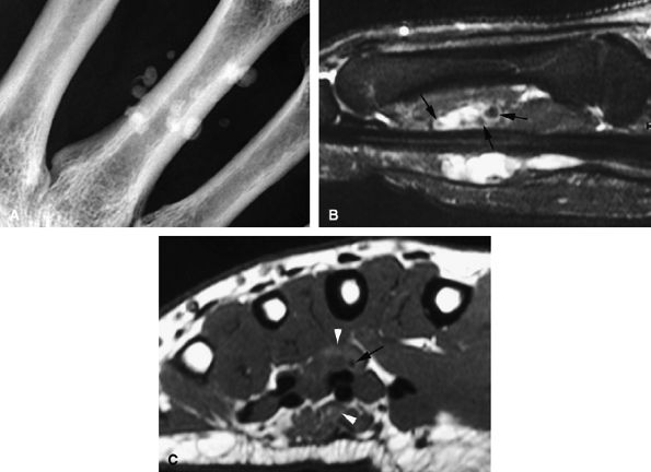
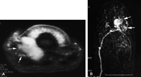
FIGURE 11.76 ● Venous malformation with phleboliths. (A) PA view radiograph and (B) sagittal STIR image showing the high-signal-intensity malformation with foci of low signal intensity (arrows) due to phleboliths. (C) Axial T1-weighted image shows small foci of high signal (arrowheads) due to thrombosis.

P.1890


MR imaging is best suited for evaluation of the extension of venous malformations. The following findings are typical:
  • Venous malformations are isointense on T1-weighted sequences and hyperintense on T2-weighted sequences.177 The high T2 signal is related to increased free water within blood pools in the venous malformation.
  • Signal intensity is often heterogeneous and areas of low signal, caused by fibrous septa, calcifications, thrombi, or hemosiderin deposition after thrombosis, may be seen on T2-weighted images.171,178
  • Phleboliths present as low-signal-intensity punctuate areas on both T1- and T2-weighted images.
  • Areas of high signal on T1-weighted images may be related to thrombi (see Fig. 11.76).
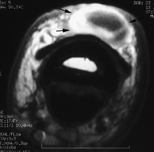
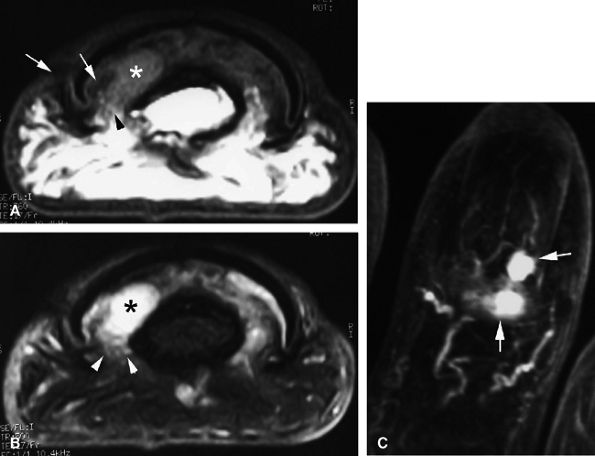
  • Articular, cartilaginous, or osseous invasion may also be depicted on MR studies (Fig. 11.77).
  • MR imaging is particularly useful in displaying the relationship of the venous malformation with adjacent structures, such as muscles, tendons, and nerves.
  • Venous malformations are frequently multifocal, have both intramuscular and subcutaneous components (see Fig. 11.77), and follow the neurovascular bundles of the affected limb.179
  • Some venous malformations may even invade nerves, causing pain. These lesions present difficult therapeutic decisions since there are risks associated with both surgery and sclerotherapy.
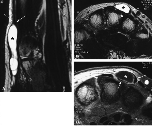
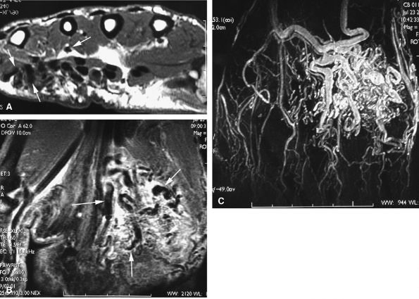
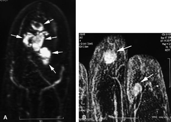
  • Nodular or tubular enhancement may be seen after gadolinium administration. MRA is complementary to standard MR studies, providing precise details of the angiographic appearance of the malformation (Fig. 11.78). MRA of the fingers is technically challenging because of the small caliber of blood vessels and their changing orientation. The MRA technique that is most suited to the fingers is a 3D coronal acquisition after gadolinium administration. This rapid technique (requiring less than 30 seconds for acquisition) yields high spatial resolution and is not dependent on vessel orientation. Injection of a gadolinium test dose allows precise determination of maximum arterial enhancement.180 Temporal resolution remains inferior to DSA.4
Angiography is not indicated because venous malformations are partially opacified at the late venous phase and there is pooling of contrast material within dilated vessels organized as numerous lobules.181 Direct puncture venography allows

P.1891


better angiographic assessment of the venous malformation than arteriography alone.116

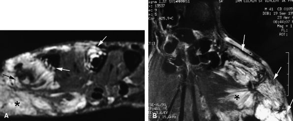
FIGURE 11.77 ● Venous malformation with bony involvement. Axial STIR (A) and coronal post-contrast fat-suppressed T1-weighted image (B) of vascular malformation infiltrating the thenar eminence, the three first metacarpals (arrows), and the subcutaneous tissues of the thumb (asterisks).
Lymphatic Malformations
Lymphatic malformations are congenital lesions seen more frequently in the cephalic, axillary, and thoracic regions than in the fingers. The terms “lymphangioma” and “cystic hygroma” should be replaced by lymphatic malformation.
Clinically, lymphatic malformations present as nonpulsatile masses identical to venous malformations; isolated intramuscular lesions are rare. They may suddenly increase in volume and become painful to palpation. On ultrasound scans, they present as multiple large anechoic, fluid-filled cavities separated from one another by septa, unlike venous malformations, which present as hypoechoic heterogeneous masses. They are avascular and no Doppler signal is found.
On MR examination there is a fluid-filled macrocystic or microcystic mass that demonstrates low signal intensity on T1-weighted images and high signal intensity on T2-weighted sequences.179 Fluid–fluid levels are sometimes found, perhaps related to intralesional bleeding (Fig. 11.79). After intravenous gadolinium injection, enhancement of the wall and

P.1892


septa may be seen, similar to that seen in other cystic tumors. Venous malformations, on the other hand, exhibit enhancement of their bloody contents.182

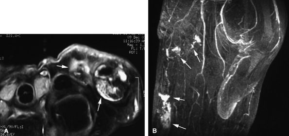
FIGURE 11.78 ● Venous malformation. (A) Axial post-contrast fat-suppressed T1-weighted image showing vascular malformation invading the fourth intermetacarpal space and the fifth metacarpal (arrows). (B) MR angiogram of multifocal vascular malformation with a distal extension toward the lateral aspect of the fifth finger (arrows).
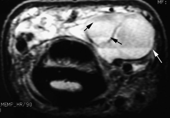
FIGURE 11.79 ● Vascular malformation with multiple lobules and fluid–fluid levels (arrows).
Angiography is not indicated for diagnosis of lymphatic malformations because they do not opacify. Aspiration of the fluid within the lesion with cytologic examination is indicated. Percutaneous sclerotherapy may be useful in lymphatic or venous malformations. Although it may not be a definitive treatment, it is useful for alleviation of symptoms, particularly pain.
Arteriovenous Malformations
AVMs present as warm, reddish masses with superficial dilated drainage veins. Auscultation may reveal a systolic bruit, and there may or may not be a thrill at palpation. Overlying skin abnormalities and hemorrhage are frequently seen due to cellular hypoxia. Intramuscular lesions are usually limited to a single muscle group.
Identification of pulsatile flow is a strong argument in favor of a vascular lesion with an important arterial component. Arteriovenous shunts lead to an increase in the mean velocity of red blood cells, a decreased resistance within the afferent artery, an increased peak systolic velocity, and arterialization of the efferent vein. Follow-up color Doppler imaging can document decreased inflow arterial flow rates and normalization of the resistive indexes in these high-flow malformations.116
On MR examination, visualization of numerous tubular structures displaying an absence of signal on T1- and T2-weighted images suggests a high-flow vascular malformation.179,183 These signal voids correspond to either an arterial flow or an arterialized venous flow (Fig. 11.80). Unlike hemangiomas, there is no “tumoral” soft tissue mass within an AVM.
Angiography reveals arteriovenous shunts, large feeding arteries, and early venous drainage.181
Hemangiomas
As mentioned earlier, the term “hemangioma” should be reserved for real vascular tumors. In cases of vessels displaying abnormal morphogenesis, the term “vascular malformation” should be used.172,184,185 The term “infantile

P.1893


hemangioma” should be used to refer to a lesion occurring in a child. Pediatric cutaneous vascular lesions and hemangiomas are usually not present at birth; they become clinically evident within the first month of life, exhibit a rapid growth phase in the first year, and involute and spontaneously regress to nearly complete resolution by 7 years of age. By definition, an adolescent or adult patient cannot have a true hemangioma.116

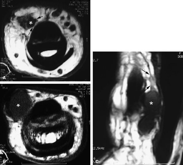
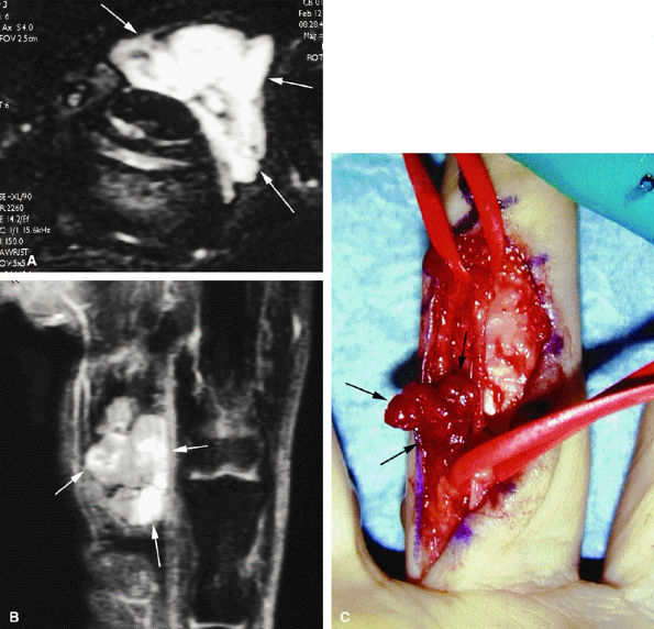
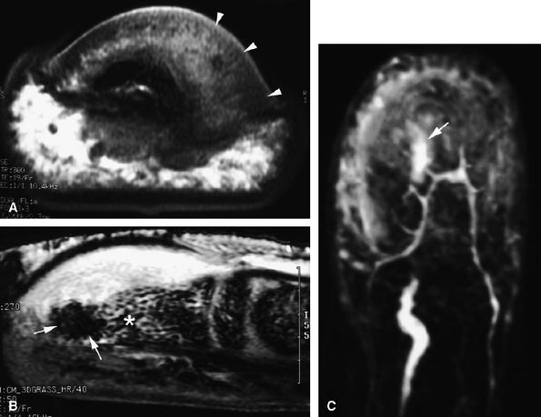
FIGURE 11.80 ● Arteriovenous malformation. (A) Axial T1-weighted image, (B) coronal post-contrast fat-suppressed T1-weighted image, and (C) MR angiogram showing a high-velocity vascular malformation of the hypothenar eminence with flow void artifacts (arrows). The angioarchitecture is better assessed with MR angiography.
Intramuscular hemangiomas are a rare separate entity affecting striated muscle; they are usually found in teenagers or young adults. They are formed by a soft tissue mass and abnormal vessels and are usually tender and firm to palpation. A single muscle is usually involved, and the mass may lead to a deformity of the involved region. Nonvascular elements such as fat, muscle, bone, fibrous tissue, hemosiderin, and thrombus are often present within the lesion.186 Unlike infantile hemangiomas, they appear rapidly and never regress. Any muscle may be involved, including the intrinsic muscles of the hand.
FIGURE 11.81 ● Hemangioma on (A) axial STIR, (B) coronal post-contrast fat-suppressed T1-weighted images, and (C) operative view. The hemangioma (arrows) appears as a soft tissue mass with a very high signal on the STIR image and partial strong enhancement after contrast administration.
The rapid growth of these lesions may suggest a malignant process and lead to a biopsy. Although malignant vascular tumors are exceedingly rare in the hand, they should be considered in the presence of tumor necrosis. Possible malignant processes include angiosarcoma, epithelioid sarcoma, and Kaposi sarcoma.178
Doppler examination depicts a soft tissue mass exhibiting rapid flow. The association of arterial and weak venous Doppler signals suggests the possibility of a hemangioma or AVM.
MR examination reveals a soft tissue mass that demonstrates hyperintense signal on both on T1- and T2-weighted images, with strong enhancement after intravenous injection of gadolinium. The signal is particularly intense on T2-weighted sequences with fat suppression.171,183 Signal voids, corresponding to high-flow vessels, may be seen within the lesion (Fig. 11.81). Although differentiation from a vascular malformation may be difficult, absence of a soft tissue component

P.1894


is the most reliable sign. Identification of high-flow vascular structures exhibiting signal voids on both T1- and T2-weighted images rules out a venous malformation and favors the diagnosis of an AVM or an intramuscular hemangioma.

Angiography displays hypervascularization formed by arteries and arterioles similar to those found in AVMs, but there is no early venous drainage. Biopsy is seldom necessary but may be performed to rule out a highly vascular soft tissue tumor. Intramuscular hemangiomas present with characteristic features at histologic examination.182,187,188 Surgical excision is the best treatment option for intramuscular hemangiomas, occasionally preceded by embolization.
Hemangiomas may arise in a flexor tendon sheath, in which case symptoms and ultrasound findings mimic subacute tenosynovitis. The lesion does not invade the flexor tendon itself and may be completely excised.189 Histologic examination reveals a synovial hemangioma with hemorrhagic changes. Episodes of bleeding may provoke sharp pain and a rapid swelling of the tendon sheath.
Lipomas
Lipomas are benign soft tissue masses of mature adipocytes usually seen in elderly patients. Most occur proximally in the thenar and hypothenar eminences; very rarely they occur more distally.190 Fingers are an uncommon location (less than 5% of cases). The clinical presentation is of a slowly growing asymptomatic mass. Pain and paresthesia, when present, are due to deep nerve compression.
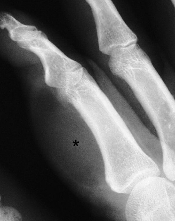
FIGURE 11.82 ● Lipoma of the index finger. Oblique view radiograph shows a low-density palmar mass (asterisk) in the soft tissues.
Lipomas are depicted on plain films and CT as low-density soft tissue masses (Fig. 11.82). Parosteal lipomas are associated with cortical irregularities of the phalanx and possible intralesional calcifications.191 The ultrasound appearance of lipomas varies widely (from hypoechoic to hyperechoic), depending on the number of internal interfaces between fatty and connective tissue.192
The diagnosis is obvious on MR images, which display a mass with high signal intensity on T2-weighted images and a lack of signal on fat-suppressed images, identical to subcutaneous fat. Heterogeneities are due to intralesional strands of fibroconnective septa (Fig. 11.83). On post-gadolinium fat-suppressed images, lipomas enhance, and nodular enhancement must raise the suspicion of a rare liposarcoma.
Fibrolipohamartomas and Macrodactyly
Fibrolipohamartomas, also called lipomatous hamartomas or neural fibrolipomas, are very rare tumors of children and young adults in which fatty and fibrous tissues infiltrate the epineurium and perineurium and surround the median nerve and its terminal branches.193 The mass involves mainly the forearm and the wrist, but more distal extension may occur. The radial and ulnar nerves are occasionally involved. Pain and paresthesia are due to carpal tunnel syndrome.194 Nearly

P.1895


one third of cases are associated with macrodactyly (macrodystrophia lipomatosa) with bony and soft tissue overgrowth.195

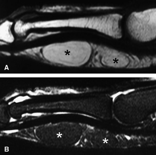
FIGURE 11.83 ● Lipoma. Sagittal T1-weighted image (A) and STIR image (B) depicting a bilobed lipoma (asterisks) of the palmar aspect of the proximal phalanx. The lesion demonstrates high signal on the T1-weighted image and low signal on the STIR image, similar to subcutaneous fatty tissue.
Plain films show macrodactyly of the second and third digits, which are subject to early osteoarthritis. CT and MR demonstrate a characteristic cable-like appearance of the tumor, with a hypertrophic appearance of the median nerve, common digital nerves, and proper digital nerves. Low-signal-intensity thickened nerve bundles and fibrous strands are embedded within a predominantly fatty mass.196,197 Rare cases of predominant involvement of the proper digital nerves have been reported (Fig. 11.84).198
Neurogenic Tumors
Neurogenic tumors such as schwannomas and neurofibromas may involve digital nerves. An hybrid neurogenic tumor with features of a schwannoma and retiform perineuroma primarily affects digital nerves.199 Most are solitary, affect patients between 20 and 50 years of age, and are not associated with neurofibromatosis type I.125 Plexiform schwannomas may be associated with macrodactyly.200
FIGURE 11.84 ● Macrodystrophia lipomatosa of the thumb. Axial (A and B) and sagittal (C) T1-weighted images depict thickening of the subcutaneous fatty tissue of the palmar and medial aspect of the thumb (asterisk). A fibrolipoma of the two first interdigital nerves demonstrates a cable-like pattern (arrows).
On clinical examination there is a palpable mass with nerve irritation under pressure. The mass is firm and fixed deeply. On MR images the lesions have sharp margins, and after gadolinium administration all or part of the tumor enhances. A cystic component may also be visualized. The signal is very high on T2-weighted images, and the tumor is often seen on the distal course of a proper digital nerve (Fig. 11.85). Differentiation of a schwannoma from a neurofibroma may be difficult on MR examination. Schwannomas are suspected when a low-signal peripheral capsule is depicted and when the proper digital nerve seems peripherally displaced by the tumor. Axial images are the most accurate in displaying these relationships. The so-called target sign (a myxoid/fluid periphery and a fibrous/collagenous center) is highly specific for a neurofibroma but is not sensitive, particularly at the fingers. The main differential diagnosis is neuromas (see discussion above on Nerve Trauma).
FIGURE 11.85 ● Schwannoma of the proper digital nerve. (A) Coronal T2-weighted 3D gradient-echo image. Axial T1-weighted image before (B) and after (C) gadolinium injection. The tumor is visualized as a round mass with a peripheral capsule (arrows) along the course of the proper digital nerve (arrowhead). The mass demonstrates high signal on the T2-weighted image and enhancement after injection of gadolinium.

P.1896


Extraskeletal Chondromas
Extraskeletal chondromas are well-defined cartilaginous masses located in the soft tissues of the finger. These very rare tumors have a predilection for the hand: this location accounts for 55% of all such soft tissue chondromas.186,201 The clinical presentation is of a slowly growing mass of the finger with deep attachment to the tendon, tendon sheath, joint capsule, or periosteum. Plain films may be negative, may demonstrate intralesional calcifications (33% to 70% of cases), or may show an extrinsic cortex erosion of the phalanx.202 Chondromas may be located only in the soft tissues, such as in the nail bed,203 in which case the nail bed is enlarged without abnormalities of the underlying phalanx. Calcifications are helpful for diagnosis but are present in only 60% of cases.204 MR imaging is highly specific and depicts a cartilaginous mass that demonstrates low signal intensity on T1-weighted images and very high signal intensity on T2-weighted images. After contrast administration, small lesions show peripheral enhancement and larger lesions a more central enhancement, delineating the lobules (Fig. 11.86).205 Intratumoral low-signal areas may reflect calcifications.
Malignant Tumors
Soft tissue sarcomas of the hand are extremely rare and follow a rather slowly growing and indolent course. Because they are located in tight anatomic compartments and are usually noticed by the patient early in their course, they are generally small at presentation. Surgical excision without amputation may be sufficient if a biopsy after a wide tumor resection shows clear margins. Because they are small and do not cause major complaints in young patients, sarcomas may mistakenly be believed to be benign lesions. Any deep-seated tumor that is firm and larger than 3 cm should be considered potentially malignant.206
FIGURE 11.86 ● Chondroma of the nail bed. (A) Sagittal T2-weighted 3D gradient-echo image. Note high signal and lobulated margins (asterisks). Pressure bone erosion of the distal phalanx (arrowheads) can also be seen. (B) Axial post-contrast T1-weighted image showing lobulated type of enhancement (asterisks).

P.1897


The most common soft tissue tumors of the hand are epithelioid sarcoma, synovial cell sarcomas, and malignant fibrous histiocytoma.207 Clear cell sarcomas, liposarcomas, neurofibrosarcomas, and malignant schwannomas are less common.208 The goal of MR examination is not to show differential patterns but to assess tumor extension in the different compartments of the hand and to display the relationships of the tumor mass with the main neurovascular bundles. Axial T2-weighted images and post-enhancement T1-weighted images are the most effective. Potential pitfalls in interpretation include small multilocular lesions, which may be confused with vascular malformations or a ganglion cyst,209 and epithelioid sarcoma, which may mimic nodules of Dupuytren's disease. Early biopsy of all unusual fibrotic lesions on the palm is recommended.210
Bone Tumors and Pseudotumors
Benign Tumors and Pseudotumors
Benign bone tumors of the hand are far more common than malignant tumors, and most are of cartilaginous origin (enchondromas, juxtacortical chondromas, osteochondromas).
Enchondromas
Enchondromas are the most common bone tumors of the hand. The absolute incidence is not known since most lesions are asymptomatic and go undiagnosed. The median age at presentation is 35 years, and the main site is the phalanges. Most tumors are solitary, but multiple enchondromas in a predominantly unilateral distribution are seen in Ollier's disease and are associated with multiple hemangiomas of the skin in Maffuci's syndrome (Fig. 11.87).211 When in multiple locations, tumors that show recent growth or cause pain should be further studied for malignant transformation to a chondrosarcoma. A painful solitary enchondroma is most likely due to a fracture (Fig. 11.88).
FIGURE 11.87 ● Lateral view radiograph showing multiple chondromas (arrows) of the hand, which may occur in Ollier's disease.
FIGURE 11.88 ● PA view radiograph showing fracture (arrow) of an enchondroma of the base of the proximal phalanx.

P.1898


MR studies of enchondromas are not usually needed, since the radiographic appearance of a lobulated radiolucent defect with bone expansion and flecks of calcification is specific. In enchondromas of small bones, calcifications are frequently lacking. A pathologic fracture is usually diagnosed on plain films. In atypical cases, MR may be used to display the cartilaginous content, which is displayed with low signal intensity on T1-weighted images and high signal intensity, identical to that of water, on T2-weighted images. There is post-contrast enhancement of the periphery and the septa (Fig. 11.89), which delineate typical cartilaginous lobules (Fig. 11.90).
FIGURE 11.89 ● Enchondroma of the proximal phalanx. Sagittal T2-weighted (A) and T1-weighted (B) images. Sagittal (C) and axial (D) fat-suppressed T1-weighted images after gadolinium administration. A centromedullary expansile lesion with cortical thinning and scalloping (arrows) can be seen. There is high signal on the T2-weighted image and lobulated peripheral enhancement.
FIGURE 11.90 ● Enchondroma of the proximal phalanx. Sagittal T2-weighted (A) and post-contrast T1-weighted (B) images depict intralesional septa (arrows) with enhancement delineating cartilaginous lobules.

P.1899


Juxtacortical Chondromas
Juxtacortical or periosteal chondromas are also common in the phalanges. The tumor is located adjacent to and partially embedded in the shaft of the phalanx or the metacarpal. The proximal third of the phalanx is most commonly involved. Plain films show a soft tissue mass adjacent to the diaphysis of the phalanx or the metacarpal, with a variable indentation and a thin bony shell.212
These patterns may be very subtle on radiographs, and CT more accurately depicts the calcifications and cortical abnormalities. MR scans confirm the presence of intralesional cartilaginous lobules and frequently display bone marrow invasion (Fig. 11.91).213,214,215
Osteochondromas and Osteochondromatous Proliferations
Osteochondromas are much less prevalent than enchondromas in the hand and most so-called osteochondromas or exostoses of the finger are actually reactive processes. These posttraumatic subperiosteal calcifications involve mainly the hands and feet. Several entities have been identified, with a common mechanism of subperiosteal hematoma,216 although previous trauma is noted in less than half of the cases. The pattern of ossification depends on the involved bone, on the extensibility of the anatomic compartment where the hematoma develops, and on the periosteal reaction.
Subungual Exostoses
Subungual exostoses, which are of uncertain etiology and pathogenesis, are sometimes found in the fingers217,218 but are more common in the great toe.126,219,220 In the hand they have a predilection for the thumb and the index finger and are usually seen in young females. A history of previous trauma is elicited in only 20% of cases,221 there have been no reports of malignant transformation, and the recurrence rate is low (11% of cases). Some subungual exostoses seem to be simple ossified hematomas.219 The relationship with the distal phalanx is variable, ranging from a peduncle, like a true osteochondroma, to a surface lesion with integrity of the phalangeal cortex. Signs and symptoms include:
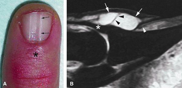
  • Pain (the main symptom)
  • A slight lifting of the dorsal aspect of the distal phalanx
  • Distal onycholysis, sometimes emerging beneath the free edge of the nail plate
  • Nail failure, which may cause surface erosion leading to infection mimicking an ingrown nail or a melanoma222
Lemont and Christman have proposed a classification system for both hereditary and acquired types of subungual exostoses.219 This classification is based on histology, radiographic patterns, location, and the age of the patient. The hereditary type (type I) occurs in patients between 20 and 30 years of age and is characterized by paronychia and medial hypertrophy of the nail bed. The acquired type (type II) occurs later, usually in patients between 40 and 60 years of age, and is characterized by distal or dorsal spurs of the phalanx without cartilage.
The triad of pain, ungual dystrophy, and a distinctive radiographic pattern is usually diagnostic. Plain films show a pedicle or sessile bony spur lying on the distal phalanx and extending into the nail bed. Unlike true osteochondromas, the cortex and the trabecular bone are not continuous with the

P.1900


distal phalanx, but this distinction may be difficult to appreciate (Fig. 11.92).223,224 Since the treatment for both entities is surgical excision, radiographic evaluation is sufficient for preoperative evaluation.

FIGURE 11.91 ● Juxtacortical chondroma. (A) Lateral view radiograph showing calcifications of the palmar soft tissues (arrows) and bone erosion of the proximal phalanx head (arrowhead). Sagittal STIR (B) and post-contrast T1-weighted images (C) show intralesional septa with cartilage signal intensity characteristics. Invasion of the head of the phalanx is well depicted (arrows).
FIGURE 11.92 ● Subungual exostoses. Lateral view radiograph showing that the trabecular bone and the cortex of the phalanx are not in continuity.
MR examination, when performed, demonstrates variable findings, and the presence of a cartilaginous component is inconstant. When present, the cartilaginous cap demonstrates bright signal intensity on proton density-weighted or gradient-echo images when it is composed of hyaline cartilage and much lower signal intensity when it is made up of fibrocartilage (Fig. 11.93). Hyaline cartilage and fibrocartilage may be mixed in the same lesion, usually indicating a reactive process. Axial images accurately show the implantation of exostoses on the phalanx and the deformity of the nail bed symmetrically on the midline or laterally (Fig. 11.94). MR examination is particularly helpful in identifying immature lesions with poor calcification (see Fig. 11.93B).
FIGURE 11.93 ● Subungual exostoses. Sagittal T1-weighted (A) and STIR (B) images showing a predominant hyaline cartilage cap (asterisk) with very high signal on the STIR image. The bony component is tiny (arrowhead). (C) Sagittal T1-weighted image in a separate case shows that the bony component is predominant (arrowheads) and the fibrocartilage cap demonstrates low signal intensity (asterisk).
Histologic examination shows similarities with florid reactive periostitis and bizarre paraosteal osteochondromatous proliferation (see discussions below). There is a proliferation of fusiform cells, with some bony and cartilaginous maturation.
Florid Reactive Periostitis
First described in 1962, florid reactive periostitis is also known as paraosteal fasciitis or periostitis ossificans. This lesion involves the small bones of the hands and feet and usually occurs in young patients, between 20 and 30 years of age.225,226,227,228,229 Histology shows a relationship with fibrous and bone tissues. Ossification is more predominant in the periphery, as is the case with traumatic ossifying myositis, which shares the same pathogenesis.230,231 Cartilaginous tissue is rare in this lesion. Clinically the patient has progressive, painful, inflammatory swelling of the finger. Plain films depict a paraosseous mass with spare calcifications and a florid lamellar or compact periosteal reaction (Fig. 11.95).232
The periosteum contains the hematoma, which induces an elongated periosteal reaction, parallel to the diaphysis. The

P.1901


bone cortex is usually intact, although some cases of bone erosions have been reported.228,233 The periosteal reaction becomes compact and integrated into the bone.

FIGURE 11.94 ● Subungual exostoses. (A) Axial proton density-weighted image depicting development of the exostoses in the lateral part of the nail bed with asymmetrical deformity (arrowheads). (B) Axial T1-weighted image in a separate case shows the lesion is seated on the midline of the nail bed (arrowheads).
Since the clinical and radiologic presentations often mimic a malignant bone tumor or infection,234 most patients with florid reactive periostitis have surgery early in the course of the disease, and there is only one report (with only three cases) describing the evolution of the lesion.235 A diagnosis of florid periosteal reaction (see Fig. 11.95) is suggested by the discrepancy between the large inflammation in soft tissues with an aggressive periosteal reaction and phalanx integrity. Follow-up, even after only a short period, shows a rapid increase in the periosteal reaction, with persistent integrity of the cortex and stability of the soft tissue mass. The frequency of recurrence

P.1902


after surgery depends on the degree of maturation of the lesion but is much less than that of bizarre paraosteal osteochondromatous proliferation.226,236

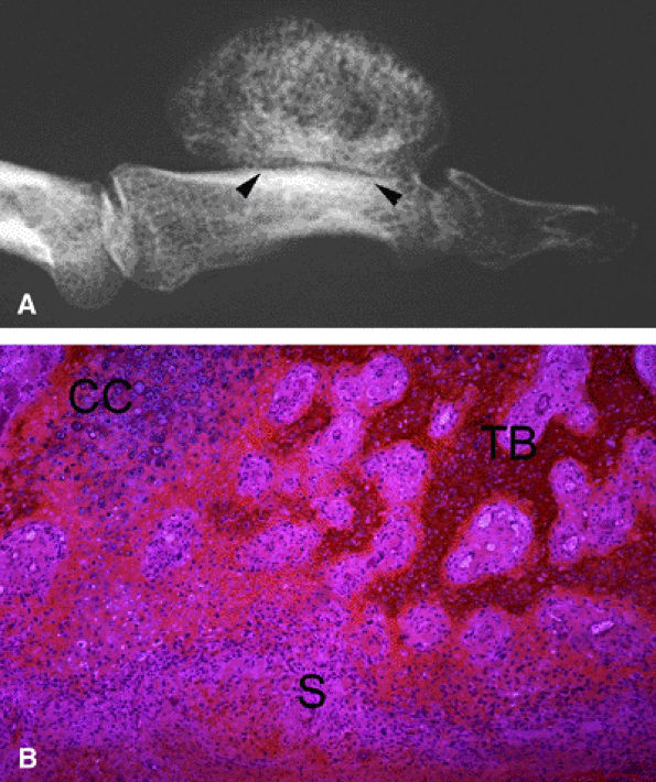
FIGURE 11.95 ● Florid reactive periostitis. (A) PA view radiograph of a paraosseous mass with sparse calcifications (arrows) and compact periosteal reaction. (B) Axial post-contrast fat-suppressed T1-weighted image showing a large inflammatory reaction in the soft tissues (asterisk) and an aggressive periosteal reaction with phalanx integrity (arrowheads).
Bizarre Paraosteal Osteochondromatous Proliferation
In 1983, Nora et al.237 described a rare lesion called bizarre paraosteal osteochondromatous proliferation (BPOP), previously called a turret exostosis.238 The lesion has a predilection for the bones of the hand, primarily the proximal and middle phalanges,239,240 but the metatarsals as well as long bones (the femur and proximal tibia) may be involved in as many 27% of cases.241,242 BPOP may occur in patients ranging from 14 to 74 years of age. The patient typically has a painless mass (unlike the painful swelling seen in florid reactive periostitis) that spreads through the dehiscent or torn periosteum and envelops bony structures.218
Plain films show a well-defined, lobulated ossifying mass in the hand, usually less than 3 cm, with a pedicle or sessile bony attachment (Fig. 11.96). The appearance is similar to an osteochondroma, but the underlying cortex is intact without true continuity with the ossification. There is no mass or calcification in the soft tissues. The lesion demonstrates low signal intensity on T1-weighted images and high signal intensity on fast spin-echo and STIR T2-weighted images.243 Intra-medullary phalangeal bone edema may be depicted, corresponding with fibrosis and an inflammatory reaction.244 This bony reaction may be misleading and should not be mistaken for a bone tumor or infection. The diagnosis of BPOP is indicated by the integrity of the bone cortex beneath the osteocartilaginous mass on T1-weighted images and the homogeneous enhancement of the trabecular bone after intravenous injection of gadolinium. The finding of cortex integrity is not mandatory for the diagnosis of BPOP, and differentiating BPOP from a paraosteal osteosarcoma may be difficult.245
FIGURE 11.96 ● Bizarre paraosteal osteochondromatous proliferation (BPOP). (A) Oblique view radiograph shows features similar to an osteochondroma but with an intact underlying cortex (arrowheads). (B) Histologically there is variable association of a less organized cartilage cap than in osteochondroma, maturing trabecular bone, and fusiform cells without cellular atypia in the stroma.
Cartilaginous metaplasia of periosteal tissues is probably responsible for BPOP. Histology shows a variable association of three components (see Fig. 11.96):
  • Hypercellular cartilage with calcifications and enchondral ossification. Cartilage may form a cap or lobules separated by fibrous septa in a less-organized architecture than in osteochondroma. This cartilaginous component may be minimal in older lesions.246
  • Maturing trabecular bone
  • Fusiform cells without cellular atypia in stroma
Postoperative recurrences occur in nearly 55% of cases.237,241 BPOP, florid reactive periostitis, and exostoses should be considered to be different phases of development of the same posttraumatic proliferative reaction.242 One case, followed for 6 months, showed progression from florid reactive periostitis to BPOP. However, this evolution should not be systematic.218,235
Osteoid Osteomas
Osteoid osteomas are small benign tumors with a central nidus of highly vascularized osteoblastic tissue, surrounded by a reactive sclerotic bone. Four percent of all bone tumors are osteoid osteomas, and they occur in young patients, usually in the first three decades. About 8% of osteoid osteomas involve the phalanges. They usually cause severe pain, swelling of the finger, and, when they occur in distal locations, widening and thickening of the nail plate. The pain is worst at night and is somewhat alleviated by salicylates. Probing with a pin locates a painful pressure point.
Osteoid osteomas in the phalanges often present with atypical clinical and radiologic characteristics. Radiographs may depict a more or less centrally calcified nidus smaller than 1 to 1.5 cm. Peripheral osteosclerosis and solid periostitis are commonly associated findings and may be particularly aggressive in lesions with a less centrally located nidus and in those that are more distally located (Fig. 11.97).247 On plain films this reaction may conceal the nidus. Additional

P.1903


misleading features in osteoid osteoma include the following (see Fig. 11.97):248,249

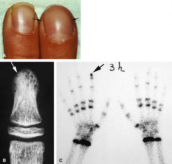
FIGURE 11.97 ● Osteoid osteoma of the distal phalanx of the index finger. (A) Dorsal aspect of the fingertip showing clubbing (arrows). (B) PA view radiograph showing osteosclerosis of the distal tuberosity of the phalanx (arrow), blurring the detection of a nidus. (C) Tc99 bone scan depicting delayed uptake of the fingertip of the index finger (arrow).
  • Absence of reactive bone
  • Monoarticular arthritis
  • Clubbing
  • Macrodactyly
  • Painless swelling
  • Absence of bony lysis
These unusual presentations may cause a delay in diagnosis and treatment. Bone scintigraphy is very helpful in these cases by highlighting a high uptake in the phalanx or metacarpal bone (see Fig. 11.97). CT scanning with thin contiguous slices is the best imaging technique for detecting the nidus. Accuracy may be improved by prior bone scintigraphy (Fig. 11.98). On MR examination the osteoid tissue is hyperintense on T2-weighted images and enhances after contrast administration. When the nidus is highly calcified and in cases of extensive bone edema and inflammation of the surrounding

P.1904


soft tissues, the nidus may be difficult to highlight with MR imaging (Fig. 11.99). Percutaneous radiofrequency ablation may be performed in the tubular bones of the hand.250

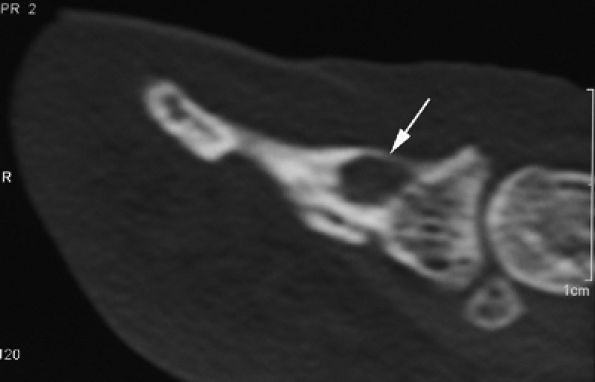
FIGURE 11.98 ● Osteoid osteoma of the distal phalanx. CT scans showing the osteolytic noncalcified nidus (arrow).
FIGURE 11.99 ● Osteoid osteoma of the distal phalanx. (A and B) The calcified nidus appears as a focus of low signal intensity (arrows), and associated asymmetric inflammatory thickening of the nail bed can be seen (arrowheads). (C) MR angiography demonstrates hypervascularization of the nidus on delayed sequences (arrow).
Giant Cell Tumors
Giant cell tumors are benign and aggressive bone tumors with a high postoperative recurrence rate. Most occur in patients 15 to 45 years of age. The bones of the hand are rarely involved, but when they are the metacarpals are the most common location and the lesions may be associated with other bone tumors in other locations (multicentric giant cell tumors) or lung metastases.251,252,253 The duration of symptoms is shorter than that seen in giant cell tumor of bone occurring in sites other than the hand.254
The characteristic radiographic appearance is of a metaepiphyseal osteolytic metacarpal lesion with a geographic pattern of bone destruction. The lesion may demonstrate internal ridges and smooth margins and possible cortical destruction (Fig. 11.100). Signal characteristics are nonspecific on MR images. The lesion may be heterogeneous, with hemorrhage, fibrosis, and highly vascularized foci (Fig. 11.101). A secondary aneurysmal bone cyst may be suspected in case of numerous fluid–fluid levels. Giant cell tumors of the hand are more likely to recur than are those in other locations (36% to 79% of cases, depending on the type of surgery performed).254
Bone Pseudotumors
Aneurysmal Bone Cysts
Aneurysmal bone cysts (ABCs) are tumor-like lesions composed of multiple cavities filled with blood. ABCs may present the same radiographic patterns as giant cell tumors of bone and may coexist in the same lesion. ABCs, however, are more expansile, are delineated by a thin bony shell, and are more likely to occur in a younger patient population. The metacarpals are the most frequently affected bones in the hand, but ABCs may be located on any other bone, including the sesamoids.255 MR findings of multiple cavities filled by blood and with fluid–fluid levels are highly evocative but not pathognomonic. Prompt therapeutic intervention is indicated because of the potential for aggressive local behavior.256
Epidermoid Cysts and Giant Cell Reaction of Bone
These lesions are discussed below in the section on Ungual and Periungual Pseudotumors and Tumors.
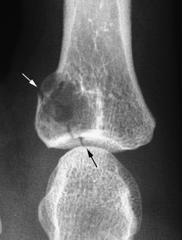
FIGURE 11.100 ● Giant cell tumor of the metacarpal. (A) Oblique view radiograph showing an expansile osteolytic lesion (arrows) of the distal metaphysoepiphysis of the fourth metacarpal. (B) One year later, there is an increase of expansion, cortex osteolysis, and numerous intralesional septa. (C) Sagittal T2-weighted image of the right knee shows the appearance of an identical lesion in the superior tibia.
FIGURE 11.101 ● Giant cell tumor of the distal phalanx on an axial T1-weighted image before and after injection of gadolinium. The post-contrast image shows strong enhancement of the tumor invading the nail bed (arrows). Asymmetrical deformity of the nail bed is also seen.

P.1905


P.1906


Malignant Bone Tumors
Malignant bone tumors of the hand are extremely rare and are almost always chondrosarcomas. Secondary chondrosarcomas may develop from a benign, pre-existing enchondroma or osteochondroma. In the hand, there is a high risk (up to 50%) of malignant transformation in patients with multiple enchondromas (Ollier's disease).214,256 Chondrosarcomas most commonly occur in elderly patients, with a slight female predominance. The proximal phalanx is usually affected, and the lesions are often of low histologic grade (grade I).257,258 Clinical symptoms may be vague, and the disease may be present for over 10 years before diagnosis.259
On plain films a metacarpal or phalangeal chondral tumor is easily detected. The diagnosis of chondrosarcoma may be difficult, however, particularly in grade I lesions, since the classic deep and extensive endosteal scalloping of cartilaginous lobules seen on long bone tumors does not occur in the hand. In addition, enchondromas of the small bones of the hand are commonly expansile and show deep cortical scalloping. A cortex fracture is a common complication. The diagnosis of a malignant tumor should be considered only if there are focal areas of ill-defined osteolysis and calcifications in the soft tissues (Fig. 11.102).260
FIGURE 11.102 ● Chondrosarcoma of the metacarpal. (A) PA view radiograph showing a slightly expansile osteolytic lesion of the proximal third of the metacarpal. Intralesional calcifications (arrows) are compatible with an enchondroma, but cortex osteolysis with periosteal reaction (arrowheads) is unusual. (B) At follow-up 3 months later, there has been a significant increase in size and extensive cortex osteolysis (arrowheads).
MR imaging is particularly helpful in depicting bone erosion and tumor invasion of the soft tissues (Fig. 11.103). The typical lobular architecture of the cartilage is well demonstrated on T2-weighted images and after injection of gadolinium.256 Although in the hand chondrosarcomas show a low metastatic potential compared with tumors in other sites, ray resection or digital amputation is recommended to avoid local recurrence.259,261
Ungual and Periungual Pseudotumors and Tumors
Except for subungual exostoses, which are discussed in the section on Osteochondromas and Osteochondromatous Proliferations, pseudotumor and tumors that are most commonly

P.1907


found in the periungual area are discussed below. Tumors of the perionychium may be difficult to diagnose because of its anatomic characteristics. Symptoms, growth, and above all the appearance of a tumor may be modified by the presence of the adjacent nail plate. Deep tumors originating close to the nail root are covered by the posterior nail fold, and their only sign may be nail dystrophy. It is important that all suspicious lesions of the nail unit be carefully evaluated by radiography and biopsy. A complementary imaging modality (ultrasonography or MR imaging) may be helpful in difficult cases by confirming and accurately locating the periungual mass.

FIGURE 11.103 ● Chondrosarcoma (asterisk) of the proximal phalanx. (A) STIR image showing a centromedullary tumor with high signal intensity compatible with cartilage content. (B) Axial post-contrast fat-suppressed T1-weighted image showing intralesional diffuse enhancement with cortex osteolysis and extension toward the soft tissues (arrows).
Normal Anatomy
Sagittal Plane
The nail plate itself, which is composed of keratin, a highly organized scleroprotein that causes dramatic shortening of relaxation times, does not produce a signal on MR images.262 It is, however, outlined by other structures and is thus indirectly depicted in its full length on sagittal images. The ventral aspect of the nail plate is well defined by the high signal of the epidermal layer of the matrix and the nail bed, but its dorsal aspect is not visible since no signal is produced at the interface with air. Application of petroleum jelly to the nail plate before positioning the hand in the coil provides a high level of contrast level with the dorsal aspect of the nail plate, regardless of the sequencing protocol used (Fig. 11.104). Because of the chemical shift artifact, nail thickness may be underestimated by approximately 0.2 mm, which is significant since the normal nail plate thickness is only 0.5 to 1 mm.263,264,265 On 3D gradient-echo images there may be a magnetic susceptibility artifact, seen as a low-signal area around the free edge of the nail plate. The nail plate is very thin close to the nail root and is surrounded by the thin high-signal-intensity matrix cul-de-sac (see Fig. 11.104; Fig. 11.105). The nail plate progressively thickens as it approaches its free edge, a finding in agreement with ultrasonography reports.266,267 It is not possible to distinguish the different histologic layers of the nail plate on MR images. Whatever the sequence used, the plate always remains

P.1908


devoid of signal throughout its thickness. With ultrasonography, two layers of different hydration in the nail plate can be distinguished.268 Unlike MR images, however, ultrasound scans do not display the epidermis layer of the nail bed.

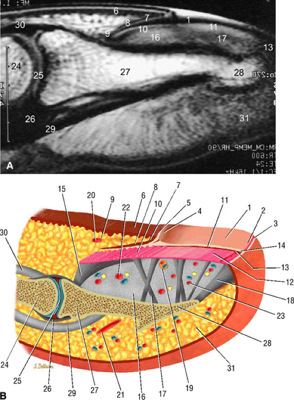
FIGURE 11.104 ● Sagittal anatomy of the nail unit. (A) T1-weighted image showing the surface of the nail plate (arrows) highlighted by petroleum jelly deposits. (B) Dorsal oblique view of the nail unit: 1, nail plate; 2, onychodermal band; 3, free edge of plate; 4, lunula; 5, cuticle; 6, proximal nail fold; 7, inferior aspect of proximal nail fold or eponychium; 8, proximal or dorsal nail matrix; 9, cul-de-sac; 10, intermediate or ventral nail matrix; 11, nail bed epithelium ridges; 12, nail bed corium; 13, hyponychium; 14, distal groove; 15, matrix phalangeal ligament; 16, submatrical hypersignal area; 17, network of collagenous fibers; 18, hyponychio-phalangeal ligament; 19, glomus body; 20, proximal dorsal arterial arch; 21, distal dorsal arterial arch; 22, distal matrix arterial arch; 23, nail bed arterial arch; 24, middle phalanx; 25, distal interphalangeal joint; 26, volar plate; 27, distal phalanx; 28, tuberosity of distal phalanx; 29, flexor digitorum profundus tendon; 30, terminal band of extensor tendon; 31, pulp.
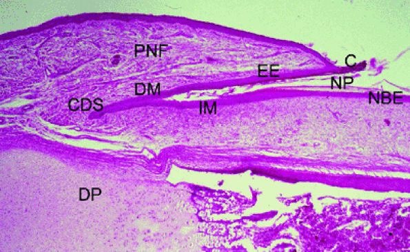
FIGURE 11.105 ● Photomicrograph of nail matrix in sagittal section with hematoxylin and eosin staining. PNF, proximal nail fold; EE, epithelium eponychium; C, cuticle; DM, dorsal matrix; IM, intermediate matrix; NBE, nail bed epithelium; CDS; matrix cul-de-sac; NP, nail plate; DP, distal phalanx.
The DIP joint has a close relationship with the nail cul-de-sac and is clearly displayed on sagittal images (see Fig. 11.104). The terminal extensor tendon inserts on the dorsal aspect of the base of the distal phalanx. The proximal matrix and distal matrix, surrounding the nail root, are also well defined on this view but are isointense with the adjacent epithelial layer of the nail bed and the ventral aspect of the proximal nail fold (or eponychium). The transition between the matrix and the nail bed is identified by the change in thickness of the epithelial layer. The epithelial layer thickens at the level of the free edge of the nail plate (the hyponychium). The lack of fat in the nail bed, except for a thin band under the nail root, eliminates chemical shift artifact.
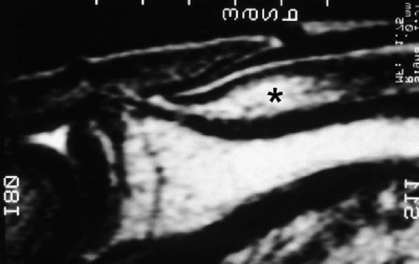
FIGURE 11.106 ● Submatrix area. Sagittal T2-weighted image depicting the oval shaped submatrix area (asterisk).
An oval area of high signal in the deep dermis beneath the nail matrix is always depicted on T2-weighted sagittal images (Fig. 11.106). This structure is related to the lunula.269 The length of this area is highly correlated to the length of the lunula. When the lunula is not visible, this dermal area is still present but does not cross the borders of the eponychium. There is a strong, homogeneous, and well-defined enhancement after injection of gadolinium. Histologic studies show a more uniform dermis in this area, with a looser connective tissue than that of the more distal nail bed. Microvascularization in this area presents a more regular vascular network than in the nail bed (Fig. 11.107).270 This area may be confused with a vascular tumor or may blur the periphery of a tumor. In doubtful cases complementary MR angiography may be helpful.
Axial Plane
The proximal or posterior nail fold, the extensor and flexor digitorum tendons, the medial and lateral collateral ligaments, and the volar plate of the DIP joint are well displayed on axial images. The transverse curvature of the nail root is regular and is surrounded dorsally by the proximal matrix and ventrally by the distal matrix (Fig. 11.108). The posterolateral borders of the nail plate are contiguous with the matricophalangeal ligaments (Fig. 11.109). The lateral nail folds emerge on more distal axial images and cover the lateral borders of the nail plate (see Fig. 11.108). The deep rima ungualum is a passage area between the nail bed and the pulp. The Flint lateral interosseous ligament forms its superficial boundary. Vascular arcades course through the rima ungualum, providing blood supply to the fingertip (Fig. 11.110). The epithelial crests of the nail bed (Fig. 11.111), which may be depicted with high-resolution axial MR images (more easily visible with chronic inflammatory hypertrophy), appear as a thin, high-signal-intensity structure. The underlying dermis is visualized as a thin superficial layer of low signal intensity and a thick deep layer that demonstrates heterogeneous signal

P.1909


P.1910


intensity. This heterogeneity is emphasized by the injection of gadolinium, which results in enhancement of the numerous glomus bodies of the nail bed (see Fig. 11.111; Fig. 11.112). Glomus bodies, which function as arteriovenous shunts, are highly concentrated in the fingertips, particularly beneath the nail plate.128 Each glomus body is a tiny encapsulated oval organ 300 μm long. The nail beds of fingers and toes contain 93 to 501 glomus bodies per square centimeter.

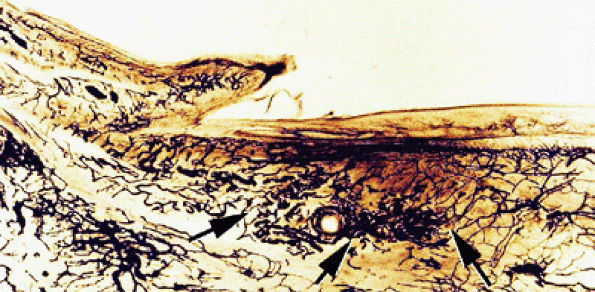
FIGURE 11.107 ● Microvascularization of the submatrix area. Photomicrograph with transparency using the Spalteholz technique, vascular injection with gelatinous India ink. The vascular networks are more regular in the submatrix area (arrows) than in the nail bed.
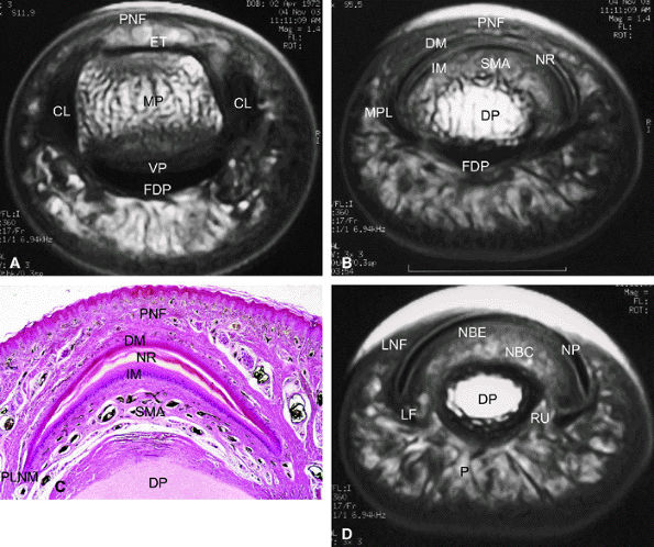
FIGURE 11.108 ● Axial anatomy of the nail unit. (A) Distal interphalangeal joint. (B) Matrix area. (C) Photomicrograph of the matrix area with hematoxylin and eosin staining. (D) Nail bed area. ET, extensor tendon; PNE, posterior nail fold; CL, collateral ligament; MP, middle phalanx; VP, volar plate; FDP, flexor digitorum tendon; MPL; matricophalangeal ligament; NR, nail root; PLNM, posterolateral corners of the nail matrix; SMA; submatrix area; DM; dorsal matrix; IM, intermediate matrix; DP, distal phalanx; P, pulp; LF, ligament of Flint; NBE, nail bed epithelium; NBC, nail bed corium; LNF, lateral nail fold; RU; rima ungualum.
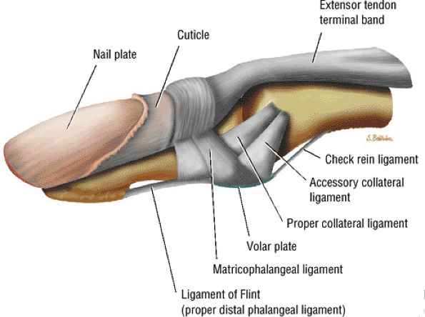
FIGURE 11.109 ● Ligaments of the distal interphalangeal joint.
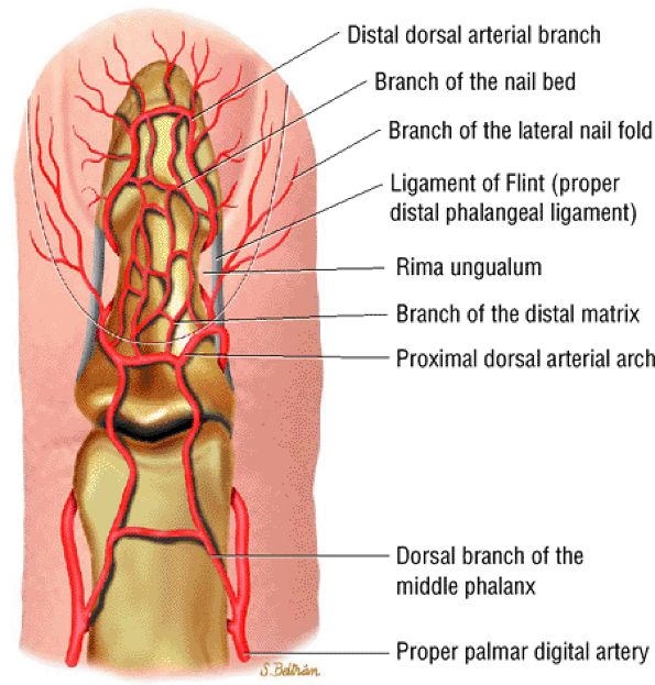
FIGURE 11.110 ● Dorsal aspect of the arterial supply of the fingertip.
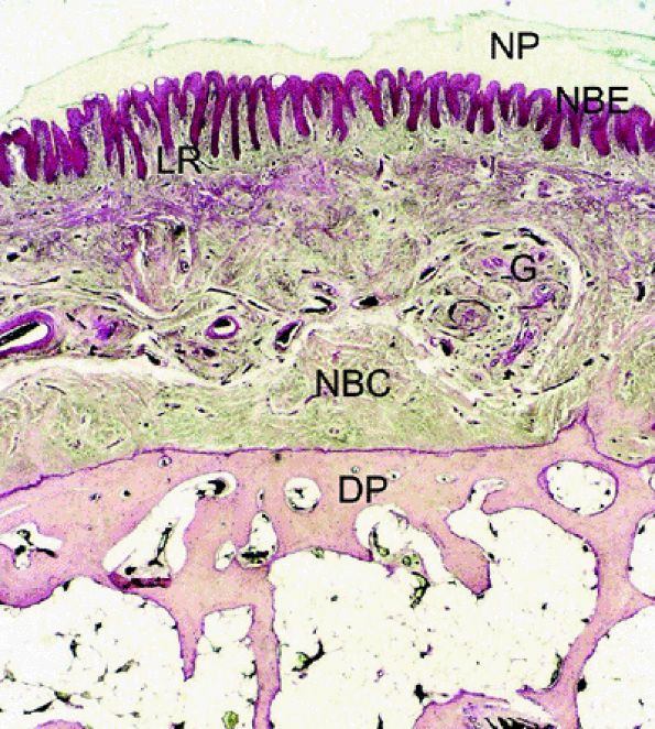
FIGURE 11.111 ● Photomicrograph of axial slice of the nail bed area with hematoxylin and eosin stain. The longitudinal ridges of the nail bed epithelium interdigitate with nail bed fibrocollagen. NP, nail plate; NBE, nail bed epithelium; G, glomus body; NBC, nail bed corium; LR, longitudinal ridges; DP, distal phalanx.
FIGURE 11.112 ● Glomus bodies. (A) Axial post-contrast 3D gradient-echo image of the nail bed showing multiple round foci representing glomus bodies (arrows). (B) Photomicrograph with transparency using the Spalteholz technique, vascular injection with gelatinous India ink, axial slice showing glomus bodies (arrows).
Coronal Plane
Coronal images are less commonly acquired for the nail unit because they are subject to partial volume artifact. Numerous elements of the nail unit are tangential to this plane. However, coronal images may be a useful addition for the assessment of the DIP joint and the distal phalanx, as well as lateral lesions invading the rima ungualum (Fig. 11.113).
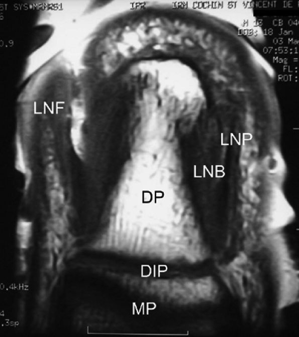
FIGURE 11.113 ● Coronal anatomy of the nail unit on T1-weighted images. MP, middle phalanx; DP, distal phalanx; DIP, distal interphalangeal joint; LNB, lateral nail bed; PNF, proximal nail fold; LNP, lateral border of nail plate.
FIGURE 11.114 ● Mucoid pseudocyst. Lateral view radiograph showing distal interphalangeal joint osteoarthritis with dorsal osteophytes (arrows) and thickening of the posterior nail fold (arrowheads).

P.1911


Pseudotumors
Mucoid Pseudocysts of Fingertip
Ganglia of the fingertip, also called mucoid cysts or pseudocysts, usually originate from the posterior nail fold. They are common in elderly patients and present therapeutic difficulties. The recurrence rate is high despite numerous proposed treatments, and accurate preoperative imaging may be helpful. Plain films usually show severe osteoarthritis of the DIP joint with huge dorsal osteophytes. The eponychium appears thickened on the lateral view (Fig. 11.114). Erosion of the dorsal cortex of the distal phalanx may also be depicted (Fig. 11.115).
Most of these cysts are solitary and located on the proximal nail fold. Their appearance on MR images is specific (Figs. 11.116 and 11.117) and includes:
  • Thin regular walls
  • Low signal intensity on T1-weighted images
  • Very high signal on T2-weighted images
  • High-resolution MR images accurately display the relationship between the cyst and the DIP joint.
  • Sagittal images commonly show osteoarthritis of the DIP joint with joint effusion and dorsal osteophytes lifting up the terminal extensor tendon.
  • Fluid around the extensor tendon is a common associated finding.
  • Synovitis of the DIP joint is somewhat highlighted after IV injection of gadolinium.
FIGURE 11.115 ● Mucoid pseudocyst. Lateral view radiograph showing distal interphalangeal joint osteoarthritis with bone pressure erosion (arrows) of the dorsal aspect of the distal phalanx.
FIGURE 11.116 ● Mucoid pseudocyst. (A) PA view photograph showing thickening of the posterior nail fold (asterisk) and nail groove (arrows) on the midline due to matrix compression. (B) Sagittal STIR image displaying a bilobed cyst of the posterior nail fold (arrows) close to the insertion of the extensor tendon (asterisk). Note the intralesional septum (black arrowheads). The cyst causes deep displacement of the nail root (white arrowhead).
FIGURE 11.117 ● Mucoid pseudocyst. Sagittal (A) and axial (B) T2-weighted images depicting a small cyst (arrows) seated in the matrix cul-de-sac with compression of the dorsal and intermediate matrix (arrowheads).

P.1912


Intracystic septa, seen in 39% of cases, are best visualized on T2-weighted images.271 Administration of gadolinium produces early faint peripheral enhancement that with time spreads toward the center of the cyst. This diffusion of contrast is similar to the intra-articular diffusion of IV gadolinium through the synovium at the level of the knee.272 However, a true synovial membrane is not found in digital cysts, apart from a possible peduncle.273
In most cases a peduncle connecting the cyst and the DIP joint is identified on MR examination. When present, the peduncle is lateral, beneath the insertion of the extensor digitorum tendon on the base of the distal phalanx (Fig. 11.118). Preoperative identification of the peduncle is important in making decisions about surgical technique, since in the traditional surgical procedure the peduncle must be tied off or removed to avoid frequent recurrences.274 With the skin flap technique, a newly proposed procedure, the communication between the joint and the cyst may seal itself during the healing process that occurs after a flap is raised and the cyst resected from the undersurface of the flap extending to the DIP joint. In this procedure no skin is excised, and removal of the osteophytes is not necessary.275 Identification of the peduncle by preoperative injection of methylene blue mixed with hydrogen peroxide into the palmar aspect of the DIP joint has been proposed, but it is technically difficult and time-consuming.276
FIGURE 11.118 ● Peduncle of a mucoid pseudocyst. Axial STIR image shows a laterally located peduncle (arrow) beneath the insertion of the extensor digitorum tendon (arrowhead).
Satellite cysts, when present, are also well displayed by MRI (Fig. 11.119).130
In 22% of cases, mucoid cysts have a sagging multiloculated pattern.277 This type of cyst may be difficult to detect clinically unless the typical signs of swelling and discharge of a thick fluid from the proximal nail fold are found. On MR examination, no connection with the DIP joint is seen (Fig. 11.120). These cysts may develop independently from the underlying joint and are caused by increased production of hyaluronic acid due to fibroblast metaplasia. This process is not unlike that which occurs in cutaneous myxomas with a focal storage of mucoid material in the dermis.
Although mucoid cysts develop into the nail bed in 30% of cases,277 this location has not been well studied and is rarely mentioned in the literature. If the patient presents with a painful cyst, misdiagnosis of glomus tumor is possible, and MR imaging is helpful in detecting and correctly diagnosing this type of cyst. When the cyst is large, erosion of the cortex of the underlying phalanx may occur in the confined space of the nail bed (Fig. 11.121). These cysts are located in the dermis beneath the nail matrix, close to the DIP joint. Matrix compression may induce a fissure of the nail plate with a claw deformity. Most often, the cyst is bilobed with a proximal component in the posterior nail fold (Fig. 11.122). Less commonly, the cyst extends into the pulp (Fig. 11.123). The submatrical extension may be clinically occult and responsible for recurrence.
FIGURE 11.119 ● Multiple mucoid pseudocysts. Sagittal T2-weighted image shows multiple cysts in the posterior nail fold and the pulp (arrows).
FIGURE 11.120 ● Overhanging multiloculated mucoid pseudocyst. Axial T2-weighted images show the cyst extending on both sides of the posterior nail fold (arrows) and the pulp (arrowhead).
FIGURE 11.121 ● Subungual mucoid pseudocyst. Sagittal STIR (A) and post-contrast T1-weighted (B) images of a cyst seated in the nail bed (asterisks) with slight peripheral enhancement after contrast administration. The nail matrix and the nail bed (arrows) are lifted by the cyst. Slight pressure bone erosion of the distal phalanx (arrowheads) can also be seen.
FIGURE 11.122 ● Subungual mucoid pseudocysts. Sagittal T2-weighted image of bilobed cysts. There is a proximal cyst in the posterior nail fold (arrow) and a distal cyst in the nail bed (arrowheads).
FIGURE 11.123 ● Subungual mucoid pseudocyst. Sagittal T2-weighted image of a subungual cyst (arrow) with extension toward the pulp (arrowheads).

P.1913


P.1914


Epidermal Inclusion Cysts
Epidermoid cysts of the finger are rare pseudotumors. They may be located anywhere along the finger, even in a tendon, but the most common site is the distal phalanx.278 They are usually secondary to trauma with implantation of epidermis into subcutaneous tissue or even into bone.279 Old injuries often go unnoticed. Epidermal inclusion cysts may also develop on a scar after surgery.277 The patient presents with a progressively enlarging phalanx and obvious clubbing. When present, pain is of late onset, sometimes caused by a pathologic fracture. Histology shows an epidermoid cyst filled with orthokeratin and lined with a thin layer of epidermis. Radiographs depict a round, sharply rimmed erosion of the distal phalanx without septa or peripheral sclerosis (Fig. 11.124).280 Early in the disease, bone erosion is absent or subtle and is occult on radiographs.
MRI shows a regular mass invading the distal phalanx with a slightly heterogeneous content and intermediate signal intensity on T1-weighted images and partially high signal intensity on T2-weighted images. After gadolinium administration, there is either no enhancement or heterogeneous enhancement of the cyst.281 A thin regular rim of high signal intensity, identical to that of normal epidermis, is due to the peripheral epidermal layer (Fig. 11.125).282–285 The site of an old penetrating injury may be marked by dark artifacts on gradient-echo images (Fig. 11.126). Subungual epidermoid inclusions are a superficial variant.286 Axial MR images show protrusions of the nail bed epithelium into the uppermost bed stroma. The bed epithelium is thickened and hyperplastic, resulting in subungual keratosis, onycholysis, or even clubbing.
Giant Cell Reaction of Bone
Giant cell reaction of bone is a rare reactive process occurring predominantly in the distal phalanx.287 This osteolytic lesion has sharp and sclerotic borders and may mimic a epidermoid cyst or a glomus tumor.288,289 Usually the lesion is expansile, with partial destruction of the cortex and a misleadingly aggressive appearance.290 MR findings are similar to those seen in an epidermoid cyst. Axial images may depict extension in the soft tissues adjacent to the phalanx.
Tumors
Glomus Tumors
Glomus tumors arise from glomus bodies, which are particularly numerous in the dermis of the nail bed. High-resolution MR imaging can depict normal glomus bodies on T2-weighted images and after injection of gadolinium (see Figs. 11.111 and 11.112). The classic triad of severe intermittent pain, localized tenderness, and cold sensitivity is evocative but occurs infrequently. Plain films are not sensitive, and a bony erosion of the distal phalanx, similar to that seen with epidermal inclusion cysts, is seen in less than 20% of cases (Fig. 11.127). MR imaging is helpful in the diagnosis, depicting the tumors in 68% of cases.1 The mean diagnostic delay, reported as ranging from 4 to 7 years, needs to be shortened.291,292,293,294
FIGURE 11.124 ● Epidermal inclusion cyst. PA view radiograph of fracture (arrows) of a clear-cut round erosion of the distal phalanx.
Glomus tumors, which may be considered hamartomas, result from hyperplasia of one or several elements of the glomus bodies.291 In 1924, Masson described several histologic variants.295 Because histologic composition has no prognostic significance, it is not routinely mentioned in pathologic reports. However, the MR signal characteristics of a glomus tumor depend on its histologic composition, and knowledge of these variants is important in understanding the variations in tumor signal.1 Three types of variants are generally seen:
  • The vascular type is composed of numerous vascular lumens. Enhancement is very high after injection of gadolinium, and the signal is high on T2-weighted images.296 MR angiography shows early enhancement in the arterial phase that increases on the delayed venous acquisition (Fig. 11.128).297,298
  • The cellular or solid type of glomus tumor is composed mainly of a proliferation of epithelioid cells (glomus cells) with a relative paucity of vascular lumens. This type of tumor is difficult to detect with MR imaging. Its signal is close to that of the normal dermis of the nail bed on all sequences (Fig. 11.129). Injection of gadolinium, even with MR angiography, is of little use. Using 3D gradient-echo imaging with thin contiguous slices is the most helpful by depicting a peripheral capsule or a slight bone erosion on the dorsal aspect of the phalanx.
  • The mucoid type of glomus tumor is characterized by mucoid degeneration of the stroma, which demonstrates mild enhancement after gadolinium administration. On T2-weighted images it is seen with very high signal intensity because of the large amount of water in the stroma (Fig. 11.130). Recently it has been shown that this subtype of glomus tumor coexpresses alpha-smooth muscle actin and CD34 in neoplastic cells, an important finding regarding the differential diagnosis of these lesions and the relationship of perivascular neoplasms.299,300
FIGURE 11.125 ● Epidermal inclusion cyst. (A) Sagittal T1-weighted images before and after injection of gadolinium show an expansile bone inclusion of the distal phalanx (asterisk) that does not enhance after contrast administration. (B–D) Postoperative epidermal inclusion cyst in a separate case. (B) Axial STIR image shows a cyst with variable signal and a low-signal component (asterisk). On axial T1-weighted images before (C) and after (D) injection of gadolinium, there is a thin rim of high signal intensity, identical to that of normal epidermis (arrows). No bone involvement is seen.
FIGURE 11.126 ● Epidermal inclusion cyst of the posterior nail fold. Sagittal 3D gradient-echo image displays a polylobed cyst of the posterior nail fold (arrows) with intralesional septa. Note the artifact (asterisk) from a previous trauma.
FIGURE 11.127 ● Glomus tumor of the fingertip. Lateral view radiograph showing bone pressure erosion (arrows) of the dorsal aspect of the distal phalanx beneath the matrix area.
FIGURE 11.128 ● Vascular-type glomus tumor (asterisk) of the nail bed with the most common signal characteristics. (A) Axial T2-weighted image. T1-weighted images before (B) and after (C) injection of gadolinium. (D) MR angiogram. The tumor is located on the midline with an underlying bone erosion (arrowheads). The signal is high on T2-weighted images and slightly high on T1-weighted images. There is strong post-contrast enhancement on T1-weighted images and MR angiography.
FIGURE 11.129 ● Solid-type glomus tumor. (A) Axial T2-weighted image. T1-weighted image before (B) and after (C) injection of gadolinium. The tumor is in the lateral part of the nail bed (arrows) and is faintly visible on all sequences.
FIGURE 11.130 ● Mucoid-type glomus tumor. (A) Axial STIR image of a glomus tumor demonstrates very high signal in the lateral nail bed (asterisk). (B) On an MR angiogram, faint tumor enhancement is seen on delayed sequences (arrows).

P.1915


P.1916


P.1917


It is not unusual for glomus tumors to contain a combination of these three histologic elements (Fig. 11.131).
The tumor margins are usually well defined by a peripheral pseudocapsule. This capsule, a reactive response of the surrounding connective tissue, demonstrates very low signal intensity on all sequences, although it is more readily visible on T2-weighted images or 3D gradient-echo images (Fig. 11.132). In some cases, the tumor margins are ill-defined, and injection of gadolinium, particularly with MR angiography, may depict small foci of tumor extending into the nearby nail bed (Fig. 11.133). In these cases some adhesions with the nail bed are often noted during surgery.
The importance of local invasion of the capsule, which is found on histologic examinations in less than 2% of cases,301 is debatable. However, the risk of recurrence is definitely high if some tumor tissue is left in situ during surgery of these ill-defined lesions. The reported recurrence rate ranges from 12% to 24%.294,302,303 MR imaging appears to be particularly helpful in evaluating cases of recurrent pain after surgery (Fig. 11.134).298,304
FIGURE 11.131 ● Mixed-type glomus tumor. Axial post-contrast 3D gradient-echo image of a glomus tumor shows a partial highly vascularized component close to the midline (arrows).
Rarely, patients present with multiple recurrences of tumors with ill-defined borders. In this situation, glomangiosarcoma, a rare malignant variant of the glomus tumor, should be considered.305 Glomangiosarcomas have been reported in several anatomic locations, but there is only one report of its localization to the hand, despite the fact that its benign counterpart is most frequently found there. There is also only one report of a glomangiosarcoma that has metastasized.
FIGURE 11.132 ● Peripheral capsule of glomus tumor. Axial T2-weighted image shows a peripheral capsule with a low signal (arrows).
FIGURE 11.133 ● The ill-defined margins of a glomus tumor shown on (A) an axial STIR image and (B) an MR angiogram. On the axial STIR image, a glomus tumor of the lateral part of the nail bed is seen extending toward the pulp via the rima ungualum (arrows). The lateral borders are not well defined. On the MR angiogram, the tumor also displays poorly defined lateral borders with lateral and proximal extension (arrows).
FIGURE 11.134 ● Postoperative recurrence of glomus tumor. Axial T1-weighted images before (A) and after (B) injection of gadolinium and (C) MR angiogram. Artifacts from the previous lateral surgical approach (arrows) can be seen, and there is tumor recurrence in the lateral part of the nail bed (asterisk). The lateral margins are blurred by scar tissue (arrowheads). On the MR angiogram, two contiguous tumors (arrows) can be seen. The proximal lesion displays ill-defined borders.
FIGURE 11.135 ● Multiple glomus tumors. (A) MR angiogram depicting five glomus tumors in the same fingertip (arrows). (B) MR angiogram in a separate case shows glomus tumors of the fingertips of two adjacent fingers (arrows).

P.1918


P.1919


Multiple glomus tumors may arise in the hand or in the same fingertip (Fig. 11.135), and some cases have been reported in association with neurofibromatosis type 1.306 MR angiography depicts these multiple sites and is essential in planning an appropriate surgical approach.307
In most cases, the tumor is located in the subungual area, in the supporting tissue of the nail bed or the matrix. The lesion is usually deep, close to the periosteum of the underlying phalanx. In this location tumors smaller than 3 mm are difficult to depict with ultrasonography.308,309 On MR images cortical bone erosion is often seen on axial images although it was occult on radiographs (see Fig. 11.128). Axial images are needed to distinguish tumors on the median line from those of the lateral part of the nail bed, which sometimes extend into the pulp via the rima ungualum (see Fig. 11.133). The surgical approach is planned according to the size and location of the tumor. Lateral-type tumors may be excised by a lateral approach; median tumors may require a transungual approach. Sagittal images are used to determine the relationship between the tumor and the nail matrix.
FIGURE 11.136 ● Glomus tumor, pulp location. (A) Sagittal T2-weighted and (B) post-contrast fat-suppressed T1-weighted images show a palmar glomus tumor of the fingertip (arrows). Fat suppression is necessary to detect the tumor enhancement.
Occasionally the tumor is located in the pulp or the posterior nail fold (Figs. 11.136 and 11.137). In this case, the fatty tissue of the hypodermis surrounding the tumor completely changes the signal characteristics and contrast between healthy

P.1920


tissue and tumor. On T1-weighted images the low-signal-intensity tumor is seen, surrounded by high-signal-intensity fat. After gadolinium administration, tumor enhancement is only visible on fat-suppressed images (see Fig. 11.136).

FIGURE 11.137 ● Glomus tumor, palmar location. (A) Axial post-contrast T1-weighted image and (B) MR angiogram of a glomus tumor located in the third intermetacarpal space (asterisks) between the interosseous and lumbrical muscles.
Glomus tumors are easily distinguished from other vascular lesions, such as venous hemangiomas and arteriovenous malformations, by their characteristic blood flow artifacts and vascular pedicles. Subungual extraskeletal chondromas may mimic a glomus tumor, but the peripheral enhancement pattern is different.310
Epithelial Tumors
Benign epithelial tumors of the nail apparatus (e.g., warts, eccrine poroma, subungual papilloma, subungual linear keratotic melanonychia, keratin cysts) are numerous, and in most cases MR imaging is not needed because the clinical findings are obvious and it would not be helpful because specific abnormalities cannot be depicted. Two lesions, however (distal digital keratoacanthomas and onychomatricomas), may be aggressive or present specific MR features and are discussed below.
FIGURE 11.138 ● Keratoacanthoma. (A) PA view radiograph shows a well-defined lytic lesion of the distal phalanx (asterisk). (B) Sagittal post-contrast 3D gradient-echo image illustrates a deep infiltrating nodule with a central area of low signal (asterisk) invading the distal phalanx. The tumor borders are ill-defined and there is peripheral inflammation.
Distal Digital Keratoacanthomas
Keratoacanthomas are rare, benign, but rapidly growing tumors located in the most distal part of the nail bed.311 The lesion may start as a small and painful keratotic nodule beneath the free edge of the nail plate and may resolve spontaneously with reossification of the underlying bony defect.312 The differential diagnosis is a subungual squamous carcinoma.313
Plain films depict a well-defined cup-shaped lytic lesion of the phalanx underlying the subungual nodule. MRI shows a deep infiltrating dome-shaped nodule with a homogeneous signal (intermediate on T1-weighted lesions and hyperintense on T2-weighted lesions) and strong post-contrast enhancement invading the distal phalanx. A central area of low signal may indicate a central plug of horny material filling the crater, but this is an inconstant finding (Fig. 11.138). The margins of the tumor may be ill-defined due to edema in the surrounding tissues.

P.1921


Onychomatricomas
Onychomatricomas should be suspected based on the clinical signs of a filamentous tufted tumor in the matrix of a funnel-shaped nail.314,315,316 Histology shows epithelial proliferation of the matrix or surrounding epidermis. The lobules are delimited by normal basal cells and are composed of keratinocytes identical to those of the matrix.317 After removal of these parakeratotic cells, an invagination resembling the infundibulum of a hair follicle remains. Clinically, onychomatricoma appears as a multifaceted tumor that can be mimicked by longitudinal melanonychia and/or onychomycosis.318 Since cases of Bowen's disease presenting as onychomatricoma have been reported, histologic assessment of all forms of onychomatricoma is necessary, especially for those associated with a pigmented band.319
FIGURE 11.139 ● Onychomatricoma. Sagittal (A) and axial (B) T1-weighted images show the tumor core (asterisk) in the matrical area and invagination of the lesion into the funnel-shaped nail plate (arrows). Distal filamentous expansions (arrowheads) are better depicted on the axial image.
MR imaging of onychomatricomas shows specific patterns (Fig. 11.139) and may be helpful in diagnosing misleading cases.125 Sagittal MR images are essential to highlight the tumor core in the matrical area and invagination of the lesion into the funnel-shaped nail plate. There is a low-signal-intensity center on all sequences, with a peripheral rim of signal identical to that of normal epidermis. The distal part with the filamentous extensions is of higher signal intensity on T2-weighted images due to a mucoid stroma. Axial images accurately show the holes in the substance of the nail plate, filled with the filamentous extensions.
FIGURE 11.140 ● Fibrokeratoma. Sagittal (A) and axial (B) 3D gradient-echo images of a tumor involving the ventral aspect of the proximal nail fold with epithelial invagination (arrows), which is an incidental matrix producing a pseudonail of collagen. Overlying acanthotic epidermis displays signal intensity identical to that of normal epidermis (arrowheads).
Fibrous Tumors
Fibrous tumors can develop in the perionychium and present with a wide range of clinical patterns despite relative histologic uniformity. In fact, Koenen's tumor, acquired fibrokeratoma, and dermatofibroma may represent different stages in a clinical continuum.
Fibrokeratomas may be multiple and located beneath the nail plate, but most emerge from the proximal nail fold and grow in a splint of the nail plate.320 Biopsy is the rule, since Bowen's disease may simulate a fibrokeratoma.321,322 Fibrokeratomas are thought to consist of newly formed collagen.323 The lesion may be septated.
MR images highlight the deep implantation close to the nail root, and the component emerging from the proximal nail fold is clearly depicted.277 The signal characteristics of the tumor vary depending on its histologic type. Dense tumors with numerous collagen bundles demonstrate very low signal on all sequences, and those with a mucoid stroma demonstrate high signal on T2-weighted images (Fig. 11.140). Overlying

P.1922


acanthotic epidermis displays signal intensity identical to that of normal epidermis. On MR images displaying involvement of the ventral aspect of the proximal nail fold, epithelial invagination (see Fig. 11.140) may be visualized. This invagination acts as an incidental matrix and produces a pseudonail of collagen.

FIGURE 11.141 ● Knuckle pad. Axial T1-weighted image before (A) and after (B) injection of gadolinium. (C) MR angiogram. A knuckle pad is visualized as a highly vascularized dorsal mass (asterisk) infiltrating the lateral part of the extensor apparatus. Low-signal foci (arrows) are due to dense collagen areas.
Knuckle pads are asymptomatic, persistent, keratotic nodular plaques that involve the dorsal aspect of the interphalangeal joints.125 Histology reveals hyperkeratosis associated with thickened collagen bundles similar to the palmar nodules in Dupuytren's disease.324 Knuckle pads may produce contraction by invasion of the extensor apparatus.325 Ultrasonography and MR images accurately show the relationship between the extensor apparatus and the plaque (Fig. 11.141). MR signal characteristics are not specific, and knuckle pads, like other fibrous lesions rich in collagen, demonstrate a rather low and heterogeneous signal on T1- and T2-weighted images.277
Fibromas are painless slow-growing nodules that can develop in any epidermal structure of the nail unit.326 Multiple and bilateral periungual fibromas sometimes represent an oligosymptomatic form of tuberous sclerosis.327,328 Radiographs may depict bone erosion and thickening of the soft tissue. There are no calcifications. Ultrasonography documents the solid and poorly vascularized pattern of the lesion but is nonspecific. Findings on MR are similar to those of knuckle pads. Superficial acral fibromyxoma is a recently reported entity characterized by a rich mucoid stroma visualized with high signal intensity on T2-weighted images.326,329
Arthritis
Although radiographs remain the primary modality for hand imaging in degenerative and inflammatory arthritides, MR imaging has the advantage of allowing differentiation of all the affected elements, bone marrow edema, bone erosion, cartilage destruction, soft tissue edema, joint effusion, and synovial pannus. With MR examination it is possible to identify early changes in arthritis before any radiographic changes are seen, and to assess the degree of disease activity. The use of MR imaging of the hand is particularly useful in the evaluation of rheumatoid arthritis.
Degenerative Arthritis (Osteoarthritis)
As mentioned, plain films are the primary imaging modality used to diagnose and monitor osteoarthritis (OA) of the fingers. Radiographs are readily available, of low cost, and reproducible. However, detection of early abnormalities is not possible, and more sensitive imaging modalities, such as ultrasonography and MR imaging, are useful in documenting these early changes. In OA there are both destructive lesions (joint space narrowing, bone cysts, and deformities) and productive remodeling (osteophytes and sclerosis). Osteoarthritis in the hand may represent a specific primary form of OA with a strong genetic component. The occurrence and course of primary generalized OA with Bouchard's and Heberden's nodes

P.1923


is clearly influenced by genetic factors.330 Other significant risk factors include trauma and occupation. Incidence and severity are increased in women over 50 years of age, and multiple joints in the hand are likely to be involved. Clinical and radiologic findings are specific.331 The most frequently affected joints in the hand are the interphalangeal joints of the long fingers and thumb. Both PIP and DIP joints are often involved simultaneously, but isolated lesions of the DIP joint are not uncommon. In contrast, the MCP and PIP joints are the most commonly affected in rheumatoid arthritis. OA of the fingers may also be secondary to crystal-induced arthropathies, with a predilection for the second and third MP joints.

MR Appearance
Abnormalities are similar in both early and chronic OA and include:
  • Cartilage loss
  • Bone edema
  • Synovial enhancement
  • Osteophytosis
  • Erosions
Cartilage degradation is progressive and diffuse in these non-weight-bearing joints, but diffuse thinning of the normally 1-mm-thick cartilage may be difficult to appreciate on MR images.3 The commonly associated subchondral changes are often more obvious.
Subchondral Bone Changes
Bone edema, sclerosis, and cyst formation are associated with OA to varying degrees. Bone edema is the earliest manifestation of OA in experimental models,332 but its significance is controversial. Osteonecrosis is also associated with OA and may be a factor in bone edema. The presence of bone edema seems to correlate with pain and activity of OA, but even in the knee, where it has been most extensively studied, its importance is debated (Fig. 11.142).333,334,335,336,337,338
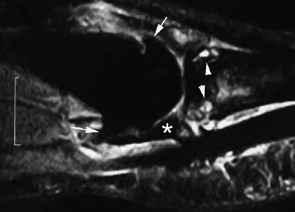
FIGURE 11.142 ● Osteoarthritis of the PIP joint on (A) a coronal proton density fat-suppressed image and (B) a sagittal post-contrast fat-suppressed T1-weighted image. Erosive osteoarthritis with foci of subchondral bone edema (asterisks), a bone cyst (arrowheads), and capsuloligamentous thickening (black arrows) are seen. A possible thin channel between the cyst and the joint (white arrow) or diffuse synovitis (small circles) may also be seen.
Bone sclerosis is a reparative process in the trabecular bone that appears after microtrauma and predominates in the pressure segments of the joint with vertical and horizontal extension. It is a characteristic feature of OA and helps to differentiate it from inflammatory diseases, such as rheumatoid arthritis. It is easily depicted on plain films and less easily on MR images. T1-weighted images are the most sensitive in detecting bone sclerosis, which appears as subchondral areas of low signal intensity.
Various terms have been used for subchondral bone cysts, including geodes, synovial cysts, and subarticular pseudocysts.339 The lesion may result from an intrusion of synovial fluid into the subchondral bone via a cartilage fissure or from foci of osteonecrosis due to increased stress in the subchondral bone.340 MR imaging is more sensitive than plain films in identifying these cysts. Unlike bone erosions associated with inflammatory disease, which are found at the junction of cartilage and bone, bone cysts in OA develop in the sclerotic portions of bone and may communicate with the joint through a thin channel (see Fig. 11.142). The MR signal characteristics of these cysts are also different. Degenerative bone cysts demonstrate fluid signal with a lack of or only faint and thin peripheral enhancement after contrast administration, whereas marginal inflammatory bone erosions demonstrate strong and diffuse enhancement. A large bone cyst may be mistaken for a giant cell tumor or an enchondroma in the fingers.
Osteophytes
Osteophytes result from reparative processes and are a distinctive feature of OA. Marginal osteophytes involve vascularization of the subchondral bone marrow, with calcification of the overlying cartilage and endochondral

P.1924


ossification.331 Osteophytes contain bone trabeculae and bone marrow and are usually covered with cartilage. Stress at the capsular insertions may lead to the development of capsular osteophytes along the direction of capsular pull. Dorsal osteophytes of the DIP joint may be large and aggressive, affecting the extensor tendon and generating a mucoid pseudocyst (see Fig. 11.114).271

Synovial Changes
Synovitis may be present from the onset of OA and is a reactive phenomenon. Some proliferation may be due to articular debris. This inflammatory reaction may be responsible for pain and stiffness, particularly in cases of erosive OA of the DIP joints.340 The degree of synovial inflammation may be evaluated on MR images and used to classify OA patients in clinical trials and could help to identify those who might benefit from synovium-targeted therapy.341 Erosive OA is a variant of primary generalized OA with the same symmetric joint distribution and a significant inflammatory reaction (see Fig. 11.142). Bony erosions are depicted on plain films, and MR images may show a true synovial inflammation. Erosions may also be due to pressure atrophy, since they begin in the center of the joint with the typical “seagull wing” pattern of the joint space.
Capsuloligamentous Changes
Collateral ligament thickening or tears have been reported in OA of the fingers (see Fig. 11.142).2 Degenerative lesions of the volar plate demonstrate irregular thinning (Fig. 11.143), and these lesions contribute to subluxations and malalignment of the PIP and DIP joints. Heberden's nodes are described at the DIP joint and Bouchard's nodes at the PIP joint. They are characteristic of primary generalized or Kellgren's OA in genetically predisposed postmenopausal women330 and are caused by overgrowth of the phalangeal condyles and capsule-ligamentous thickening. MR imaging shows that they occur at regions where soft tissue bulges through the capsule between the extensor tendon and the collateral ligaments (Fig. 11.144).
FIGURE 11.143 ● Osteoarthritis of the MP joint. Sagittal STIR image showing marginal osteophytes (arrows), subchondral bone edema (arrowheads), and degenerative lesions of the volar plate (asterisk) with irregular narrowing.
Rheumatoid Arthritis
Techniques for MR Examination
MR examinations are now used extensively in cross-sectional and observational studies as well as controlled clinical trials to assess disease activity and joint damage in rheumatoid arthritis (RA). Further studies are needed to determine which regions should be scanned for optimal assessment of joint damage and disease activity. The number of sequences may be reduced if only limited MR outcome data are required. Although low-field devices may be used in clinical trials, resolution and tissue discrimination must not be sacrificed.
The finger joints are affected early and are often the first joints involved in rheumatoid arthritis.342 They are also good markers for assessment of overall disease activity. Clinical studies have often focused on the MP joints because they are easier to image than the more complex wrist and the smaller interphalangeal joints. The Outcome Measures in Rheumatology Clinical Trials (OMERACT) and the European League Against Rheumatism (EULAR) have studied the role of MR in RA and developed a scoring system based in part on findings in the MP joint. The OMERACT 2002 RA MRI scoring system (RAMRIS) is based on the following:343,344,345
  • Synovitis is assessed in three wrist regions and in each MP joint. The first carpometacarpal and first MP joints are not scored. The scale is 0 to 3'0 is normal; 1 to 3 (mild, moderate, severe) is determined by thirds of the

    P.1925


    presumed maximum volume of enhancing tissue in the synovial compartment.

  • Bone erosions are scored separately for each bone (wrist, metacarpal bases, MP joints'metacarpal heads and phalangeal bases). The scale is 0 to 10, based on the proportion of eroded bone compared to the “assessed bone volume,” judged on all available images. A score of 0 is no erosion; 1 is 1% to 10% of bone eroded; 2 is 11% to 20% of bone eroded; and so forth. For long bones, the “assessed bone volume” is from the articular surface (or its best estimated position if absent) to a depth of 1 cm.
  • Bone edema is also scored separately for each bone. The scale is 0 to 3 based on the proportion of bone with edema. A score of 0 is no edema; 1 is 1% to 33% of bone is edematous; 2 is 34% to 66% of bone is edematous; and 3 is 67% to 100% of bone is edematous.
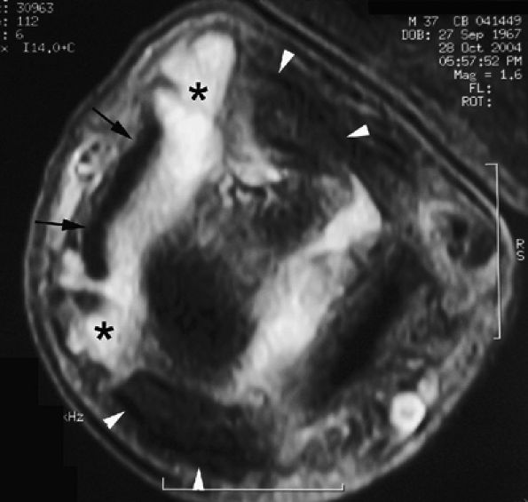
FIGURE 11.144 ● Heberden's nodes. Axial proton density fat-suppressed image shows capsulosynovial herniation (asterisks) through the space between the extensor tendon (arrows) and the collateral ligaments (arrowheads).
It is difficult to image all the joints of both hands with high spatial resolution, and standardized protocols are necessary.346 The core set of basic MR sequences should include the following:343,344,345,347,348
  • Imaging in two planes (two 2D sequences or one 3D isometric sequence) with T1-weighted images before and after IV gadolinium injection
  • T2-weighted fat-saturated sequence or a STIR sequence (Fig. 11.145).
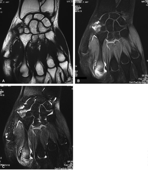
FIGURE 11.145 ● Rheumatoid arthritis MR scoring. Coronal T1-weighted image before (A) and after (B) injection of gadolinium with fat suppression. (C) T2-weighted image with fat suppression. A large field of view is needed to assess both the wrist and the metacarpophalangeal joints. Additional axial T1-weighted images are also necessary.

P.1926


Fat suppression with IV injection of gadolinium is necessary to differentiate joint effusion from synovial pannus. This technique is also useful in monitoring the patient's response to therapy.349 Dynamic contrast-enhanced MR imaging is not routinely performed but is the best technique to assess hypervascularized synovium. Evaluation of cartilage destruction of the fingers is limited by the insufficient spatial resolution.
Early-Stage Rheumatoid Arthritis
Both ultrasonography with color Doppler and MR imaging are useful in detecting early RA before changes become apparent on radiographs. MR diagnosis is based on the triad of synovitis, bone erosion, and bone edema.
Synovitis
The OMERACT RAMRIS uses the following definition of synovitis: “an area in the synovial compartment that shows above normal post-gadolinium enhancement of a thickness greater than the width of the normal synovium” (Fig. 11.146).343,344
There are many reports in the literature showing the usefulness of MR imaging in the assessment of synovitis of the fingers in RA.350,351,352,353 Most comparative studies demonstrate that MR is the gold standard for evaluating synovitis.352,354
If a diagnosis of RA is made on the basis of detection of bilateral enhancement in both wrists and/or the MP and/or PIP joints, MR can identify RA in 27% more cases than plain films.355 Numerous MR parameters can be evaluated, including synovial thickness, synovial volume, signal intensity after contrast enhancement, and a combined scoring system.343,344,356
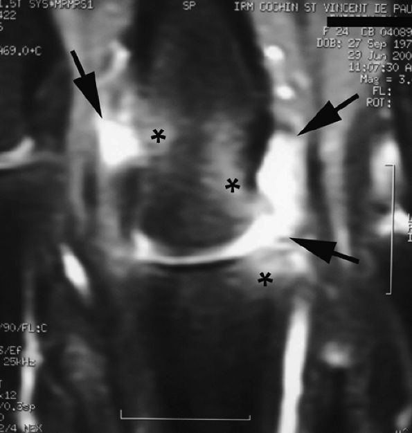
FIGURE 11.146 ● Pre-erosive inflammatory arthritis of the metacarpophalangeal joint. Coronal post-contrast fat-suppressed T1-weighted image showing enhanced synovium (arrows) and associated bone edema (asterisks).
Although ultrasound is also used to evaluate early RA, the quantification of synovial vascularization is more difficult to obtain with color Doppler technique. Several studies show a strong correlation with joint tenderness and swelling, but MR examination may also depict subclinical synovitis in early RA, particularly at the MP and PIP joints.356 The reliability of MR detection of synovitis appears high.357
Erosions
According to the OMERACT consensus, an MR erosion is defined as a “sharply marginated bone lesion with correct juxta-articular localization and typical signal characteristics visible in 2 planes with a cortical break seen in at least one plane” (Fig. 11.147).358 False-positive diagnosis of erosion is rare since MR “erosions” are found in only 2.2% of normal MP joints.359 MR erosions at MP joints have been correlated histopathologically with surface bone defects.351 Many studies have demonstrated that MR is more sensitive than plain films for erosion detection.352 However, multidetector CT remains more sensitive than MR imaging and demonstrates higher erosion scores, particularly at the metacarpal bases.360 When the erosion is accessible to ultrasonography (radial aspect of the second MP joint), the imaging modalities appear equivalent.361
The reliability of scoring of MR erosions using OMERACT RAMRIS is variable and may be improved by standardization as proposed by the EULAR-OMERACT atlas of the MP joints.362 It is a complete series of all grades of synovitis and a selection of grades of bone erosions and bone edema in the two MP joint bones (metacarpal head and phalangeal base).
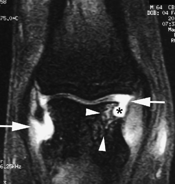
FIGURE 11.147 ● Erosive inflammatory arthritis of the PIP joint. Coronal post-contrast fat-suppressed T1-weighted images display enhanced synovium (arrows) and bone erosion (asterisk) with underlying bone edema (arrowheads).

P.1927


The volume of erosion of MP joints may be quantified using computerized techniques.347 However, it is not yet clear which joint regions provide the optimal coverage (MP joints, wrist, foot).
Bone Edema
Bone edema is a prominent feature of RA in very early disease.351,356 Bone edema is defined by the OMERACT group as “a lesion within the trabecular bone, with ill-defined margins and signal characteristics consistent with increased water content” (see Fig. 11.146).343,344 The inflammatory infiltration within the bone remains debated, as there is no histopathologic correlation. Bone edema cannot be depicted with plain films or ultrasonography. Juxta-articular osteopenia on plain films is not correlated with bone marrow edema on MR images.346 Semiquantitative scoring of bone edema is more difficult to assess than scoring of bone erosions and shows lower reliabilities.356,361 Technical difficulties in fat suppression and problems in delineating bone edema may be responsible. As bone erodes, the volume of edematous bone decreases proportionally; therefore, the maximum possible score for edema decreases as the score for erosion increases. Abnormal synovial enhancement is not specific and is described in other rheumatologic inflammatory processes and infection. However, bone marrow edema in the MP joints is more frequently seen in patients with RA.363
Disease Activity
MR measurement of synovitis and bone erosion is a valid and reliable tool for assessing disease progression and treatment response in RA of wrist and finger joints. The importance of the depiction of bone edema remains more problematic. MR may become as routinely used by clinicians as plain films. Active inflammation is detected by enhancement of synovium and subchondral tissue after injection of gadolinium. The degree of enhancement depends on the vascularization of the synovium. Several subsets of synovial changes have been identified:
  • Active inflammatory pannus (destructive and extensive enhancement)
  • Moderately active pannus (homogeneous enhancement confined to bone erosions)
  • Inactive fibrous pannus (low signal on all sequences).364 Although fibrotic pannus may enhance, it does so with lower levels and on delayed images.365,366,367
Hypervascularized synovium shows an early maximum enhancement after 1.5 minutes and after gadolinium spreads toward the joint fluid.272 Therefore, early post-enhanced images are more appropriate in the assessment of the true thickness of active synovium.365,367 The amount of synovium in the finger joints and the volume of the enhanced pannus may be efficient parameters for follow-up.368,369,370 Volumetric quantification has a 10% error rate. The synovial volume of fingers is larger in clinically active RA. The transition of synovitis to pannus represents the beginning of irreparable joint damage in the course of RA.364 There may be discrepancies between clinical, laboratory, and imaging assessment of disease activity.346
The detection of early erosive RA may have prognostic value for future bone destruction activity.364,371,372,373 The bone edema score in early RA is an excellent prognostic factor as it predicts both radiographic damage and functional outcome.356,372,373 This bone edema is correlated with disease activity (synovitis and clinical scores) and appears as a pre-erosive lesion on outcome studies.351,356,372,373 Longitudinal studies show that new erosions at the MP joints are preceded by MR synovitis.351 The median time interval between detection of an erosion using MR and its appearance on plain films is about 2 years.356 Scoring MR erosions is an outcome measure with a high sensitivity to change. It appears more sensitive than plain films and allows short-term studies (3 months, for example).361,372,373
References
1. Drapé JL, Idy-Peretti I, Goettmann S. MR imaging of subungual glomus tumors. Radiology 1995;195:507–515.
2. Tan AL, Grainger AJ, Tanner SF, et al. High-resolution magnetic resonance imaging for the assessment of hand osteoarthritis. Arthritis Rheum 2005;52:2355–2365.
3. Hodgson RJ, Barry MA, Carpenter TA, et al. Magnetic resonance imaging protocol optimization for evaluation of hyaline cartilage in the distal interphalangeal joint of fingers. Invest Radiol 1995;30:522–531.
4. Krause U, Pabst T, Kenn W, et al. High-resolution contrast-enhanced MR-angiography of the hand arteries: preliminary experiences. Vasa 2002;31:179–184.
5. Wentz KU, Frohlich JM, von Weymarn C, et al. High-resolution magnetic resonance angiography of hands with timed arterial compression (tac-MRA). Lancet 2003;361:49–50.
6. Bilecen D, Aschwanden M, Heidecker HG, et al. Optimized assessment of hand vascularization on contrast-enhanced MR angiography with a subsystolic continuous compression technique. AJR Am J Roentgenol 2004;182:180–182.
7. Moutet F, Guinard D, Corcella D. Ligament injuries of the first metacarpophalangeal joint. In: Brüser P, Gilbert A, eds. Finger Bone and Joint Injuries. London: Martin Dunitz, 1999:207–211.
8. Kahler DM, McCue FC. Metacarpophalangeal and proximal interphalangeal joint injuries of the hand, including the thumb. Clin Sports Med 1992;11:57–76.
9. Rimbeau G, Cesari B. Ligament injuries of the metacarpophalangeal joints II-V (acute and chronic). In: Brüser P, Gilbert A, eds. Finger Bone and Joint Injuries. London: Martin Dunitz, 1999:213–218.
10. Theumann NH, Pessis E, Lecompte M, et al. MR imaging of the metacarpophalangeal joints of the fingers: evaluation of 38 patients with chronic joint disability. Skeletal Radiol 2005;34:210–216.
11. Masson JA, Golimbu CN, Grossman JA. MR imaging of the metacarpophalangeal joints. Magn Reson Imaging Clin North Am 1995;3:313–325.
12. Rayan GM, Murray D, Chung KW, et al. The extensor retinacular system at the metacarpophalangeal joint: anatomical and histological study. J Hand Surg [Br] 1997;22:585–590.
13. Plancher KD, Ho CP, Cofield SS, et al. Role of MR imaging in the management of “skier's thumb” injuries. Magn Reson Imaging Clin North Am 1999;7:73–84.
14. Stener B. Displacement of the ruptured ulnar collateral ligament of the metacarpophalangeal joint of the thumb: a clinical and anatomy study. J Bone Joint Surg [Br] 1962;44:869–879.
15. Hinke DH, Erickson SJ, Chamoy L, et al. Ulnar collateral ligament of the thumb: MR findings in cadavers, volunteers, and patients with ligamentous injury (gamekeeper's thumb). AJR Am J Roentgenol 1994;163:1431–1434.
16. Schnur DP, DeLone FX, McClellan RM, et al. Ultrasound: a powerful tool in the diagnosis of ulnar collateral ligament injuries of the thumb. Ann Plast Surg 2002; 49:19–22.
17. Hergan K, Mittler C, Oser W. Ulnar collateral ligament: differentiation of displaced and non displaced tears with US and MR imaging. Radiology 1995;194:65–71.
18. Spaeth HJ, Abrams RA, Bock GW, et al. Gamekeeper thumb: differentiation of nondisplaced and displaced tears of the ulnar collateral ligament with MR imaging. Radiology 1993;188:553–556.
19. Ahn JM, Sartoris DJ, Kang HS, et al. Gamekeeper thumb: comparison of MR arthrography with conventional arthrography and MR imaging in cadavers. Radiology 1998;206:737–744.
20. Lohman M, Vasenius J, Kivisaari A, et al. MR imaging in chronic rupture of the ulnar collateral ligament of the thumb. Acat Radiol 2001;42:10–14.
21. Haramati N, Hiller N, Dowdle J, et al. MRI of the Stener lesion. Skeletal Radiol 1995;24: 515–518.
22. Romano WM, Garvin G, Bhayana D, et al. The spectrum of ulnar collateral ligament injuries as viewed on magnetic resonance imaging of the metacarpophalangeal joint of the thumb. Can Assoc Radiol J 2003;54:243–248.
23. Schubiner JM, Mass DP. Operation for collateral ligament rupture of the metacarpophalangeal joint of the fingers. J Bone Joint Surg [Br] 1989;71:338–339.

P.1928


24. Dubousset JF. Les articulations métacarpophalangiennes. In: Tubiana R, ed. Chirurgie de la main. Paris: Masson, 1980:227–234.
25. Ishizuki MD. Injury to collateral ligament of the metacarpophalangeal joint of a finger. J Hand Surg [Am] 1988;13:456–460.
26. Gee TG, Pho RWH. Avulsion-fracture at the proximal attachment of the radial collateral ligament of the fifth metacarpophalangeal joint: a case report. J Hand Surg 1982;7:526–527.
27. Höglund M, Tordai P. Ultrasound. In: Gilula LA, Yin Y, eds. Imaging of the Wrist and Hand. Philadelphia: WB Saunders, 1996:479–498.
28. Drapé JL, Dubert T, Silbermann O, et al. Acute trauma of the extensor hood of the metacarpophalangeal joint: MR imaging evaluation. Radiology 1994;192:469–476.
29. Theumann NH, Pfirmann CWA, Drapé JL, et al. MR imaging of the metacarpophalangeal joints of the fingers. 1. Normal MR and MR arthrography findings in cadavers. Radiology 2002;222:437–445.
30. Pfirmann CWA, Theumann NH, Botte MJ, et al. MR imaging of the metacarpophalangeal joints of the fingers. 2. Detection of simulated injuries in cadavers. Radiology 2002;222:447–452.
31. Faivre S, Bellumore Y, Mansat P, et al. Rupture of the radial collateral ligament of the fifth metacarpophalangeal joint. A case report with Stener effect. Chir Main 2002;21:198–201.
32. Bailie SD, Benson LS, Marymont JV. Proximal interphalangeal joint injuries of the hand. I. Anatomy and diagnosis. Am J Orthop 1996;25:474–477.
33. Raimondi P, Muset A. The proximal interphalangeal joint: lateral sprain and residual instability. In: Brüser P, Gilbert A, eds. Finger Bone and Joint Injuries. London: Martin Dunitz, 1999:235–240.
34. Gilbert A. Palmar fibrocartilage lesions. In: Brüser P, Gilbert A, eds. Finger Bone and Joint Injuries. London: Martin Dunitz, 1999:241–244.
35. Schmidt HM, Lanz U. Cutaneous ligaments. In: Schmidt HM, Lanz U, eds. Surgical Anatomy of the Hand. Stuttgart: Thieme, 2004:178–180.
36. Palmer RE. Joint injuries of the hand in athletes. Clin Sports Med 1998;17:513–531.
37. Wray BC, Young VL, Holtman B. Proximal interphalangeal joint sprains. Plast Reconstr Surg 1984;74:101–107.
38. Clavero JA, Alomar X, Monill JM, et al. MR imaging of ligament and tendon injuries of the fingers. RadioGraphics 2002;22:237–256.
39. Lutz M, Fritz D, Arora R, et al. Anatomical basis for functional treatment of dorsolateral dislocation of the proximal interphalangeal joint. Clin Anat 2004; 17:303–307.
40. Morris SF, Yang D, Milne AD, et al. Reconstruction of the proximal interphalangeal joint collateral ligaments using the Mitek Micro Arc Anchor: an in vivo biomechanical assessment. Ann Plast Surg 1999;42:124–128.
41. Imatami J, Hashizume H, Wake H, et al. The central slip attachment fracture. J Hand Surg [Br] 1997;22:107–109.
42. Sunagawa T, Ochi M, Ishida O, et al. Three-dimensional CT imaging of flexor tendon ruptures in the hand and wrist. J Comput Assist Tomogr 2003;27:169–174.
43. Bencardino JT. MR imaging of tendon lesions of the hand and wrist. Magn Reson Imaging Clin North Am 2004;12:333–347.
44. Erickson SJ, Cox IH, Hyde JS, et al. Effect of tendon orientation on MR imaging signal intensity: a manisfestation of the “magic angle” phenomenon. Radiology 1991;181:389–392.
45. Drapé JL, Silbermann-Hoffman O, Houvet P, et al. Complications of flexor tendon repair in the hand: MR imaging assessment. Radiology 1996;198:219–224.
46. Von Schroeder HP, Botte MJ. Anatomy and functional significance of the long extensors to the fingers and thumb. Clin Orthop Relat Res 2001;383:74–83.
47. Zilber S, Oberlin C. Anatomical variations of the extensor tendons to the fingers over the dorsum of the hand: a study of 50 hands and a review of the literature. Plast Reconstr Surg 2004;113:214–221.
48. Young CM, Rayan GM. The sagittal band: anatomic and biomechanical study. J Hand Surg [Am] 2000;25:1107–1113.
49. Kleinert HE, Verdan C. Report of the committee on tendon injuries. J Hand Surg [Am] 1983;8:794–798.
50. Iselin F. Plaies des tendons de la main. J Chir (Paris) 1988;125:424–430.
51. Tubiana R. Injuries to the digital extensors. Hand Clin 1986;2:149–156.
52. Blair WF, Steyers CM. Extensor tendon injuries. Orthop Clin North Am 1992; 23:141–148.
53. Aronowitz ER, Leddy JP. Closed tendon injuries of the hand and wrist in athletes. Clin Sports Med 1998;17:449–467.
54. Scott SC. Closed injuries to the extension mechanism of the digits. Hand Clin 2000;16:367–373.
55. Massengill JB. The boutonnière deformity. Hand Clin 1992;8:787–801.
56. Towfigh H, Gruber P. Surgical treatment of the boutonniere deformity. Oper Orthop Traumatol 2005;17:66–78.
57. Deshmukh NV, Sonanis SV, Stothard J. Neglected volar dislocations of the interphalangeal joint. Hand Surg 2004;9:71–75.
58. Westerheide E, Failla JM, von Holsbeeck M, et al. Ultrasound visualization of central slip injuries of the finger extensor mechanism. J Hand Surg [Am] 2003;28:1009–1013.
59. Hame SL, Melone CP Jr. Boxer's knuckle in the professional athlete. Am J Sports Med 2000;28:879–882.
60. Bentz RT, Metz JP, Topper SM. Traumatic extensor tendon dislocation in a boxer: a case study. Med Sci Sports Exerc 2003;35:1645–1647.
61. Ritts GD, Wood MB, Engber WD. Nonoperative treatment of traumatic dislocation of the extensor digitorum tendons in patients without rheumatoid disorders. J Hand Surg [Am] 1985;10:714–716.
62. Lopez-Ben R, Lee DH, Nicolodi DJ. Boxer knuckle (injury of the extensor hood with extensor tendon subluxation): diagnosis with dynamic US: report of three cases. Radiology 2003;228:642–646.
63. De Maeseneer M, Van Roy P, Jacobson JA, et al. Normal MR imaging findings of the midhand and fingers with anatomic correlation. Eur J Radiol 2005;56:278–285.
64. Al-Harthy A, Rayan GM. Congenital flexion deformity of the middle finger and sagittal band hypoplasia. J Hand Surg [Am] 2003;28:123–129.
65. Doyle JR. Anatomy of the flexor tendon sheath and pulley system: a current review. J Hand Surg [Am] 1989;14:349–351.
66. Lin GT, Amadio PC, An KN, et al. Functional anatomy of the human digital flexor pulley system. J Hand Surg [Am] 1989;14:949–956.
67. Murphy BA, Mass P. Zone I flexor tendon injuries. Hand Clin 2005;21:167–171.
68. Ficat C, Hautier S. Les plaies des tendons fléchisseurs des doigts au niveau de la main: résultat des sutures primaires. J Chir (Paris) 1975;6:533–542.
69. Newmeyer WL 3rd, Manske PR. No man's land revisited: the primary flexor tendon repair controversy. J Hand Surg [Am] 2004;29:1–5.
70. McGeorges DD, Stilwell JH. Partial flexor tendon injuries: to repair or not. J Hand Surg [Br] 1992;17:176–177.
71. Scott JR, Cobby M, Taggart I. Magnetic resonance imaging of acute tendon injury in the finger. J Hand Surg [Br] 1995;20:286–288.
72. Rubin DA, Kneeland JB, Kitay GS, et al. Flexor tendon tears in the hand: use of MR imaging to diagnose degree of injury in cadaver model. AJR Am J Roentgenol 1996;166:615–620.
73. Concannon MJ, Duffy FJ, Palmer WE, et al. Late rupture of a flexor tendon after electrical injury: tendon localization using magnetic resonance imaging'a case report. Ann Plast Surg 1996;36:84–87.
74. Kumar BA, Tolat AR, Threepuraneni G, et al. The role of magnetic resonance imaging in late presentation of isolated injuries of the flexor digitorum profundus tendon in the finger. J Hand Surg [Br] 2000;25:95–97.
75. Leddy JP. Avulsions of the flexor digitorum profundus tendon. Hand Clin 1985;1:77–83.
76. Leddy JP, Packer JW. Avulsion of the profundus tendon insertion in athletes. J Hand Surg 1977;2:66–69.
77. Smith JH. Avulsion of a profundus tendon with simultaneous intra-articular fracture of the distal phalanx. J Hand Surg 1981;6:600–601.
78. Stamos BD, Leddy JP. Closed flexor tendon disruption in athletes. Hand Clin 2000;16:359–365.
79. Cohen SB, Chhabra AB, Anderson MW, et al. Use of ultrasound in determining treatment for avulsion of the flexor digitorum profundus (rugger jersey finger): a case report. Am J Orthop 2004;33:546–549.
80. Drapé JL, Tardif-Chastenet de Gery S, Silbermann-Hoffman O, et al. Closed ruptures of the flexor digitorum tendons: MRI evaluation. Skeletal Radiol 1998; 27:617–624.
81. Tan V, Mundanthanam G, Weiland AJ. Traumatic simultaneous rupture of both flexor tendons in a finger of an athlete. Am J Orthop 2005;34:505–507.
82. Nessler JP, Amadio PC, Berglund LJ, et al. Healing of canine tendon in zones subjected to different mechanical forces. J Hand Surg [Br] 1992;17:561–568.
83. Abrahamsson SO, Lundborg G, Lohmander LS. Restoration of the injured flexor tendon surface: possible role for endotendon cells. J Hand Surg [Br] 1992;17:553–560.
84. Bhatia D, Tanner KE, Bonfield W, et al. Factors affecting the strength of flexor tendon repair. J Hand Surg [Br] 1992;17:550–552.
85. Defino HLA, Barbieri CH, Goncalves RP, et al. Studies on tendon healing: a comparison between suturing techniques. J Hand Surg [Br] 1986;11:444–450.
86. Strickland JW. The scientific basis for advances in flexor tendon surgery. J Hand Ther 2005;18:94–110.
87. Tang JB. Clinical outcomes associated with flexor tendon repair. Hand Clin 2005;21:199–210.
88. McGeorge DD, McGeorge S. Diagnostic medical ultrasound in the management of hand injuries. J Hand Surg [Br] 1990;15:256–261.
89. Corduff N, Jones R, Ball J. The role of ultrasound in the management of zone 1 flexor tendon injuries. J Hand Surg [Br] 1994;49:76–80.
90. Le Viet D. Flexor tendon lengthening by tenotomy at the musculotendinous junction. Ann Plastic Surg 1986;17:239–246.
91. Strickland JW. Flexor tendon surgery. II. Free tendon grafts and tenolysis. J Hand Surg [Br] 1989;14:368–382.
92. Finsen V. Two-staged grafting of digital flexor tendons: a review of 43 patients after 3 to 15 years. Scand J Plast Reconstr Surg Hand Surg 2003;37:159–162.
93. Ejeskär A, Irstam L. Elongation in produndus tendon repair: a clinical and radiological study. Scand J Plast Reconstr Surg 1981;15:61–68.
94. Seradge H. Elongation of the repair configuration following flexor tendon repair. J Hand Surg [Br] 1983;8:182–185.
95. Zhao C, Amadio PC, Tanaka T, et al. Effect of gap size on gliding resistance after flexor tendon repair. J Bone Joint Surg [Am] 2004;86:2482–2488.
96. Hunter JM, Salisbury RE. Flexor-tendon reconstruction in severely damaged hands: a two-stage procedure using a silicone-Dacron reinforced gliding prothesis prior to tendon grafting. J Bone Joint Surg [Am] 1971;53:829–858.
97. Feldscher SB, Schneider LH. Flexor tenolysis. Hand Surg 2002;7:61–74.
98. Bollen SR, Gunson CK. Hand injuries in competition climbers. Br J Sports Med 1990;24:16–18.
99. Moutet F. Flexor tendon pulley system: anatomy, pathology, treatment. Chir Main 2003;22:1–12.
100. Marco RA, Sharkey NA, Smith TS, et al. Pathomechanics of closed rupture of the flexor tendon pulleys in rock climbers. J Bone Joint Surg [Am] 1998;80:1012–1019.
101. Wilson SM, Roulot E, Le Viet D. Closed rupture of the thumb flexor tendon pulleys. J Hand Surg [Br] 2005;30:621–623.

P.1929


102. Voulliaume D, Forli A, Parzy O, et al. Surgical repair of flexor tendon pulley rupture in high level rock climbing. Chir Main 2004;23:243–248.
103. Bowers WH, Kuzma GR, Bynum DK. Closed traumatic rupture of finger flexor pulleys. J Hand Surg [Br] 1994;19:782–787.
104. Schoffl V, Hochholzer T, Winkelmann HP, et al. Pulley injuries in rock climbers. Wilderness Environ Med 2003;14:94–100.
105. Hauger O, Chung CB, Lektrakul N, et al. Pulley system in the fingers: normal anatomy and simulated lesions in cadavers at MR imaging, CT, and US with and without contrast material distension of the tendon sheath. Radiology 2000; 217:201–212.
106. Martinoli C, Bianchi S, Cotten A. Imaging of rock climbing injuries. Semin Musculoskelet Radiol 2005;9:334–345.
107. Kovacs P, Bodner G. High-resolution ultrasound diagnosis of the annular tendon system of the hand. Orthopade 2002;31:284–287.
108. Klauser A, Frauscher F, Bodner G, et al. Finger pulley injuries in extreme rock climbers: depiction with dynamic US. Radiology 2002;222:755–761.
109. Boutry N, Titecat M, Demondion X, et al. High-frequency ultrasonographic examination of the finger pulley system. J Ultrasound Med 2005;24:1333–1339.
110. Parellada JA, Balkisoon AR, Hayes CW, et al. Bowstring injury of the flexor tendon pulley system: MR imaging. AJR Am J Roentgenol 1996;167:347–349.
111. Gabl M, Rangger C, Lutz M, et al. Disruption of the finger flexor pulley system in elite rock climbers. Am J Sports Med 1998;26:651–655.
112. Saldana MJ. Trigger digits: diagnosis and treatment. J Am Acad Orthop Surg 2001;9: 246–252.
113. Nimigan AS, Ross DC, Gan BS. Steroid injections in the management of trigger fingers. Am J Phys Med Rehabil 2006;85:36–43.
114. Tohyama M, Tsujio T, Yanagida I. Trigger finger caused by an old partial flexor tendon laceration: a case report. Hand Surg 2005;10:105–108.
115. Kazuki K, Okada T, Naka Y. Case of trigger finger related to an intertendinous connection between the flexor tendons. J Hand Surg [Br] 2005;30:513–514.
116. Yakes WFJ, Dake MD. Angiographic and interventional procedures in the hand. In: Gilula LA, Yin Y, eds. Imaging of the Wrist and Hand. Philadelphia: WB Saunders, 1996:499–522.
117. Kadano T, Kishi A, Onishi Y, et al. Acquired digital arteriovenous malformation: a report of six cases. Br J Dermatol 2000;142:362–365.
118. Fayad L, Hazirolan T, Bluemke D, et al. Vascular malformations in the extremities: emphasis on MR imaging features that guide treatment options. Skeletal Radiol 2006;27:1–11.
119. Duncan WC. Hypothenar hammer syndrome: an uncommon cause of digital ischemia. J Am Acad Dermatol 1996;34:880–883.
120. Coulier B, Coffin D, Malbecq S, et al. Colour duplex sonographic and multislice spiral CT angiographic diagnosis of ulnar artery aneurysm in hypothenar hammer syndrome. JBR-BTR 2003;86:211–214.
121. Taute BM, Behrmann C, Cappeller WA, et al. Ultrasound image of the hypothenar hammer syndrome. Ultraschall Med 1998;19:220–224.
122. Liskutin J, Dorffner R, Resinger M, et al. Hypothenar hammer syndrome. Eur Radiol 2000;10:542.
123. Velling TE, Brennan FJ, Hall LD, et al. Sonographic diagnosis of ulnar artery aneurysm in hypothenar hammer syndrome: report of 2 cases. J Ultrasound Med 2001;20:921–924.
124. Foucher G, Sammut D, Greant P, et al. Indications and results of skin flaps in painful digital neuroma. J Hand Surg [Br] 1991;16:25–29.
125. De Beuckeleer LHL, de Schepper AM, de la Kethulle de Ryhove D, et al. Imaging of soft tissue tumors of the hand and wrist. In: Guglielmi G, van Kuijk C, Genant HK, eds. Fundamentals of Hand and Wrist Imaging. Berlin: Springer-Verlag, 2001:331–363.
126. Baran R, Haneke E, Drapé JL, et al. Tumours of the nail apparatus and adjacent tissues. In: Baran R, Dawber RPR, de Berker DAR, et al., eds. Diseases of the Nails and Their Management, 3rd ed. Oxford: Blackwell Science, 2001:515–630.
128. Cheng CA, Rockwell WB. Ganglions of the proximal interphalangeal joint. Am J Orthop 1999;28:458–460.
129. Hernandez-Lugo AM, Dominguez-Cherit J, Vega-Memije ME. Digital mucoid cyst: the ganglion type. Int J Dermatol 1999;38:533–555.
130. Theranzadeh J, Anavim A, Lin F. Radiographically ossified ganglion cyst of a finger in a swimmer. Skeletal Radiol 1998;27:705–707.
131. Abe Y, Watson HK, Renaud S. Flexor tendon sheath ganglion: analysis of 128 cases. Hand Surg 2004;9:1–4.
132. Kato H, Minami A, Hirachi K, et al. Treatment of flexor tendon sheath ganglions using ultrasound imaging. J Hand Surg [Am] 1997;22:1027–1033.
133. Ikeda K, Tomita K, Matsumoto H. Intratendinous ganglion in the extensor tendon of a finger: a case report. J Orthop Surg 2001;9:63–65.
134. Rayan GM. Intratendinous ganglion: a case report. Orthop Rev 1989;18:449–451.
135. Young SC, Freiberg A. A case of an intratendinous ganglion. J Hand Surg [Am] 1985;10:723–724.
136. Seidman GD, Margles SW. Intratendinous ganglion. J Hand Surg [Am] 1993, 18:707–710.
137. Giele H, Le Viet D. Intraneural mucoid cysts of the upper limb. J Hand Surg [Br] 1997;22:805–809.
138. Hahn P. Intraosseous ganglion in the phalanx of the ring finger. A case report. Handchir Mikrochir Plast Chir 1988;20:349–350.
139. Walker UA, Gutfleisch J, Peter HH. Case number 23: Tuberculous tenosynovitis. Ann Rheum Dis 20002;61:384.
140. Noonberg GE. Management of extremity trauma and related infections occurring in the aquatic environment. J Am Acad Orthop Surg 2005;13:243–253.
141. Van Seymontier P, Verellen K, De Jonge I. Mycobacterium marinum causing tenosynovitis: “Fish tank finger.” Acta Orthop Belg 2004;70:2719–282.
142. Hess CL, Wolock BS, Murphy MS. Mycobacterium marinum infections of the upper extremity. Plast Reconstr Surg 2005;115:55–59.
143. Esenyel CZ, Bulbul M, Kara AN. Isolated tuberculous tenosynovitis of the flexor tendon of the fourth finger of the hand. Case report. Scand J Plast Reconstr Surg Hand Surg 2000;34:283–285.
144. Powers R, Fisher M. Images in clinical medicine. Tenosynovitis due to Mycobacterium marinum. N Engl J Med 2004;351:911.
145. Cauzza E, Stauffer E, Zimmerli S, et al. Mycobacterium marinum: MR imaging and clinical course of a rare soft tissue infection. Skeletal Radiol 2004;33:409–412.
146. Lee EY, Rubin DA, Brown DM. Recurrent Mycobacterium marinum tenosynovitis of the wrist mimicking extraarticular synovial chondromatosis on MR images. Skeletal Radiol 2004;33:405–408.
147. Smith K, Fort JG. Phalangeal osseous sarcoidosis. Arthritis Rheum 1998; 41:176–179.
148. Rivera-Sanfeliz G, Resnick D, Haghighi P. Sarcoidosis of hands. Skeletal Radiol 1996;25:786–788.
149. Handa T, Nagai S, Ito I, Shigematsu M, et al. Multiple bone fractures found in a young sarcoidosis patient with long stable disease. Intern Med 2005;44:1269–1275.
150. Curco N, Pagerols X, Vives P. Subcatenous sarcoidosis with dactylitis. Clin Exp Dermatol 1995;20:434–435.
151. Ikeda K, Saito M, Sueyoshi Y, et al. Flexion contracture of fingers due to sarcoidosis'a case report. Acta Orthop Scand 1996;67:623–625.
152. Terzioglu A, Bingul F, Tuncali D, et al. Osseous destruction and rupture of the extensor tendon caused by sarcoidosis of the finger. Scand J Plast Reconstr Surg Hand Surg 2004;38:317–319.
153. Wang HT, Sunil TM, Kleinert HE. Multiple unusual complications after extensive chronic sarcoid tenosynovitis of the hand: a case report. J Hand Surg [Am] 2005;30:610–614.
154. Kostman JR, Rush P, Reginato AJ. Granulomatous tophaceous gout mimicking tuberculous tenosynovitis: report of two cases. Clin Infect Dis 1995;21:217–219.
155. Jbara M, Patnana M, Kazmi F, et al. MR imaging: arthropathies and infectious conditions of the elbow, wrist, and hand. Magn Reson Imaging Clin North Am 2004; 12:361–379.
156. Popp JD, Bidgood WD, Edwards NL. Magnetic resonance imaging of tophaceous gout in the hand and wrists. Semin Arthritis Rheum 1996;25:282–289.
157. Roulot E, Le Viet D. Primary synovial osteochondromatosis of the hand and wrist. Report of a series of 21 cases and literature review. Rev Rhum Engl Ed 1999; 66:256–266.
158. Vinchon B, Polveche G, Cordonnier D, et al. Tenosynovial osteochondromatosis of the hand. A case report. Ann Chir Main Memb Super 1991;10:343–347.
159. Bonatz E, Robbin ML, Weingold MA. Ultrasound for the diagnosis of retained splinters in the soft tissue of the hand. Am J Orthop 1998;27:455–459.
160. Monu JUV, McManus CM, Ward WG, et al. Soft tissue masses caused by long-standing foreign bodies in the extremities. AJR Am J Roentgenol 1995; 165:395–397.
161. Yacoe M, Bergman G, Ladd A, et al. Dupuytren's contracture: MR imaging findings and correlation between MR signal intensity and cellularity of the lesions. AJR Am J Roentgenol 1993;160:813–817.
162. Jelinec JS, Kransdorf MJ, Shmookler BM, et al. Giant cell tumor of the tendon sheath: MR findings in nine cases. AJR Am J Roentgenol 1994;162:919–922.
163. Llauger J, Palmer J, Roson N, et al. Pigmented villonodular synovitis and giant cell tumors of the tendon sheath: radiologic and pathologic features. AJR Am J Roentgenol 1999;172:1087–1091.
164. Averill RM, Smith RJ, Campbell CJ. Giant-cell tumors of the bones of the hand. J Hand Surg 1980;5:39–50.
165. Capelastegui A, Astigarraga E, Fernandez-Canton G, et al. Masses and pseudomasses of the hand and wrist: MR findings in 134 cases. Skeletal Radiol 1999;28:498–507.
166. De Beuckeleer LH, de Schepper A, de Belder F, et al. Magnetic resonance imaging of localized giant cell tumour of the tendon sheath. Eur Radiol 1997;7:198–201.
167. Karasick D, Karasick S. Giant cell tumor of tendon sheath: spectrum of radiologic findings. Skeletal Radiol 1992;21:219–224.
168. Fogelson MH, Dao KD, Shin AY. Intraosseous metacarpal involvement of giant cell tumor of the tendon sheath: report of 2 cases. Am J Orthop 2003;32:32–34.
169. Peh WC, Wong Y, Shek TW, et al. Giant cell tumor of the tendon sheath of the hand: a pictorial essay. Australas Radiol 2001;45:274–280.
170. Kitagawa Y, Ito H, Amano Y, et al. MR imaging for preoperative diagnosis and assessment of local tumor extent on localized giant cell tumor of tendon sheath. Skeletal Radiol 2003;32:633–638.
171. Theumann NH, Bittoun J, Goettmann S, et al. Hemangiomas of the fingers: MR imaging evaluation. Radiology 2001;218:841–847.
172. Enjolras O, Mulliken JB. Vascular tumors and vascular malformations (new issues). Advances Dermatol 1996;131:998.
173. Wassef M, Enjolras O. Les malformations vasculaires superficielles: classification et histopathologie. Ann Pathol 1999;19:3253–3264.
174. Quinn PS, Sieunarine K, Lawrence-Brown M, et al. Intramuscular hemangioma: hookwire localization prior to surgical excision. Report of four cases. Austral NZ J Surg 2001;71:62–66.
175. Enjolras O, Ciabrini D, Mazoyer E, et al. Extensive pure venous malformations in the upper or lower limb: a review of 27 cases. J Am Acad Dermatol 1997;36:219–225.
176. Dubois J, Garel L, David M, et al. Vascular soft tissue tumors in infancy: distinguishing features on Doppler sonography. AJR Am J Roentgenol 2002;178:1541–1545.

P.1930


177. Dubois J, Garel L, Grignon A, et al. Imaging of hemangiomas and vascular malformations in children. Acad Radiol 1998;5: 390–400.
178. Horcajadas AB, Lafuente JL, de la Cruz Burgos R, et al. Ultrasound and MR findings in tumor and tumor-like lesions of the fingers. Eur Radiol 2003;13:672–685.
179. Rak KM, Yakes WF, Ray JN, et al. MR imaging of symptomatic peripheral vascular malformations. AJR Am J Roentgenol 1992;159:107–112.
180. Winterer JT, Scheffer K, Paul G, et al. Optimization of contrast-enhanced MR angiography of the hands with a timing bolus and elliptically reordered 3D pulse sequence. J Comput Assist Tomogr 2000;24:903–908.
181. Burrows PE, Mulliken JB, Fellows KE, et al. Childhood hemangiomas and vascular malformations: angiographic differentiation. AJR Am J Roentgenol 1983;141:483–488.
182. Allen PW, Enzinger FM. Hemangioma of skeletal muscle. An analysis of 89 cases. Cancer 1972;29:8–22.
183. Totterman SMS, Miller RJ. MRI of the wrist and hand. In: Gilula LA, Yin Y, eds. Imaging of the Wrist and Hand. Philadelphia: WB Saunders, 1996:441–478.
184. Mulliken JB, Glowacki J. Hemangiomas and vascular malformations in infants and children: a classification based on endothelial characteristics. Plast Reconstr Surg 1982;69:412–420.
185. Kim EY, Ahn JM, Yoon HK, et al. Intramuscular vascular malformations of an extremity: findings on MR imaging and pathologic correlation. Skeletal Radiol 1999;28:515–521.
186. Kransdorf MJ, Murphey MD. Extraskeletal osseous and cartilaginous tumors. In: Kransdorf MJ, Murphey, eds. Imaging of Soft Tissue Tumors. Philadelphia: WB Saunders, 1997:317–350.
187. Beham A, Fletcher CDM. Intramuscular hemangioma: a clinicopathologic analysis of 74 cases. Histopathology 1991;18:53–59.
188. Drapé JL, Feydy A, Guerini H, et al. Vascular lesions of the hand. Eur J Radiol 2005;56:331–343.
189. Rico AA, Holguin PH, Gonzalez IG, et al. Flexor tendon synovial sheath haemangioma mimicking subacute tenosynovitis. J Hand Surg [Br] 1994;19:704–705.
190. Stuffer M, Thurner JE. Lipoma of the index digit'a very rare location. Arch Orthop Trauma Surg 1995;114:239–240.
191. Yamamoto T, Marui T, Mizuno K. Parosteal lipoma of the distal phalanx: a case report and review of the literature. Clin Orthop Relat Res 2001;389:181–184.
192. Fornage BD, Tassin GB. Sonographic appearances of superficial soft tissue lipomas. J Clin Ultrasound 1991;19: 215–220.
193. Razzaghi A, Anastakis DJ. Lipofibromatous hamartoma: review of early diagnosis and treatment. Can J Surg 2005;48:394–399.
194. Nogueria A, Pena C, Martinez MJ, et al. Hyperostotic macrodactyly and lipofibromatous hamartoma of the median nerve associated with carpal tunnel syndrome. Chir Main 1999;18:261–271.
195. Silverman TA, Enzinger FM. Fibrolipomatous hamartoma of nerve: a clinicopathologic analysis of 26 cases. Am J Surg Pathol 1985;9:7–14.
196. Evans HA, Donnelly LF, Johnson ND, et al. Fibrolipoma of the median nerve: MRI. Clin Radiol 1997;52:304–307.
197. Elsaidi GA, Wiesler ER. Lipofibromatous hamartoma of the median nerve: case presentation of MRI, ultrasound, electrodiagnostic, histologic, and surgical findings. Am J Orthop 2004;33:514–516.
198. Jung SN, Yim Y, Kwon H. Symmetric lipofibromatous hamartoma affecting digital nerves. Yonsei Med J 2005;46:169–172.
199. Michal M, Kazakov DV, Belousova I, et al. A benign neoplasm with histopathological features of both schwannoma and retiform perineurioma (benign schwannoma-perineurioma): a report of six cases of a distinctive soft tissue tumor with a predilection for the fingers. Virchows Arch 2004;445:347–353.
200. Posner MA, McMahon MS, Desai P. Plexiform schwannoma (neurilemmoma) associated with macrodactyly: a case report. J Hand Surg [Am] 1996;21:707–710.
201. Kransdorf MJ, Meis JM. From the archives of the AFIP. Extraskeletal osseous and cartilaginous tumors of the extremities. RadioGraphics 1993;13:853–884.
202. De Poulpiquet P, Segonds JM, Balaire P, et al. Chondroma of the soft tissues of the hand. Report of a recurrent case. Rev Chir Orthop 1999;85:861–864.
203. Dumontier C, Abimelec P, Drapé JL. Soft-tissue chondroma of the nail bed. J Hand Surg [Br] 1997;22:474–475.
204. Dahlin DC, Salvador AH. Cartilaginous tumors of the soft tissues of the hands and feet. Mayo Clin Proc 1974;49:721–726.
205. Nakamura R, Ehara S, Nishida J, et al. Diffuse mineralization of extraskeletal chondroma: a case report. Radiat Med 1997;15:51–53.
206. Terek RM, Brien EW. Soft tissue sarcomas of the hand and wrist. Hand Clin 1995;11:287–305.
207. Murray PM. Soft tissue sarcoma of the upper extremity. Hand Clin 2004; 20:325–333.
208. Yamamoto T, Fujioka H, Mizuno K. Malignant schwannoma of the digital nerve in a child. A case report. Clin Orthop Relat Res 2000;376:209–212.
209. Wong CH, Chow L, Yen CH, et al. Uncommon hand tumours. Hand Surg 2001; 6:67–80.
210. Erdmann MW, Quaba AA, Sommerlad BC. Epithelioid sarcoma masquerading as Dupuytren's disease. Br J Plast Surg 1995;48:39–42.
211. Van Der Woude HJ, Bloem JL. Primary osseous tumors of the hand. In: Guglielmi G, van Kuijk C, Genant HK, eds. Fundamentals of Hand and Wrist Imaging. Berlin: Springer-Verlag, 2001:365–379.
212. Feldman F. Primary bone tumors of the hand and carpus. Hand Clin 1987; 3:269–289.
213. Shimpuku E, Lee YH, Oka Y. Periosteal chondroma of the proximal phalanx of the thumb. Scand J Plast Reconstr Surg Hand Surg 2002;36:125–127.
214. Yamamoto T, Nagira K, Kurosaka M. Periosteal chondroma presenting as a subcutaneous mass in the thumb. Clin Imaging 2001;25:432–434.
215. Varma DG, Kumar R, Carrasco CH, et al. MR imaging of periosteal chondroma. J Comput Assist Tomogr 1991;15:1008–1010.
216. Yuen M, Friedman L, Orr W, et al. Proliferative parosteal process of phalanges: a unitary hypothesis. Skeletal Radiol 1992;21:301–303.
217. Lemont H, Christman RA. Subungual exostosis and nail disease and radiologic aspects. In Scher R, Daniel CR, eds: Nails: Therapy, Diagnosis, Surgery. Philadelphia: WB Saunders, 1990:250–257.
218. Norton LA: Disorders of the nails. In: Moschella SL, Hurley HJ, eds: Dermatology, 2d ed. Philadelphia: WB Saunders, 1985:1398–1400.
219. Baran R, Sayag J. Exostose sous-unguéale de l'index. Ann Dermatol Vénérol 1978;105:1075–1076.
220. Carroll RE, Chance JT, Inan Y. Subungual exostosis in the hand. J Hand Surg [Br] 1992;17:569–574.
221. Davis DA, Cohen PR. Subungual exostosis. Case report and review of the literature. Pediatr Dermatol 1996;13:212–218.
222. Velanovich V. Subungual pigmented lesion caused by bone spur: a mimic of a subungual melanoma. Military Med 1994;159:663.
223. Schulze KE, Hebert AA. Diagnosis features, differential diagnosis, and treatment of subungual osteochondroma. Pediatr Dermatol 1994;11:39–41.
225. Hutter RV, Foote FW, Francis KC, et al. Paraosteal fasciitis: a self-limited benign process that simulates a malignant neoplasm. Am J Surg 1962;104:800–807.
226. Spjut HJ, Dorfman HD. Florid reactive periostitis of the tubular bones of the hand and feet, a benign lesion which may simulate osteosarcoma. Am J Surg Pathol 1981;5:423–433.
227. Mirra JM. Parosteal tumors. In: Mirra JM, et al. Bone Tumors, Clinical, Radiologic and Pathologic Correlations. Philadelphia: Lea & Febiger, 1989:1587.
228. Jongeward RH, Martel W, Louis DS, et al. Case report 304. Florid reactive periostitis of the proximal phalanx of the left fifth finger. Skeletal Radiol 1985; 13:169–173.
229. Solana J, Bosch M, Espanol I. Florid reactive periostitis of the thumb: a case report and review of the literature. Chir Main 2003;22:99–103.
230. Choi JH, Gu MJ, Kim MJ, et al. Fibrosarcoma in bizarre parosteal osteochondromatous proliferation. Skeletal Radiol 2001;30:44–47.
231. Dorfman HD, Czerniak B. Bone Tumors. St. Louis: Mosby,1998:1139–1143.
232. Holmes WS, Pope TL, de Lange EE, et al. Case 413: Florid reactive periostitis of the proximal phalanx of the fourth finger. Skeletal Radiol 1987;16:163–165.
233. Howard RF, Slawski DP, Gilula LA. Florid reactive periostitis of the digit with cortical erosion: a case report and review of the literature. J Hand Surg [Am] 1996;21:501–505.
234. Jambhekar NA, Desai SS, Puri A, et al. Florid reactive periostitis of the hands. Skeletal Radiol 2004;33:663–665.
235. Sundaram M, Wang LL, Rotman M, et al. Florid reactive periostitis and bizarre paraosteal osteochondromatous proliferation: pre-biopsy imaging evolution, treatment and outcome. Skeletal Radiol 2001;30:192–198.
236. Rogers GF, Brzezienski MA. Florid reactive periostitis of the middle phalanx: a case report and review of the literature. J Hand Surg [Am] 1999;24:1014–1018.
237. Nora FE, Dahlin DC, Beaubout JW. Bizarre para-osteal osteochondromatous proliferation of the hands and feet. Am J Surg Pathol 1983;7:245–250.
238. Wissinger HA, McClain EJ, Boyes HH. Turret exostosis ossifying hematoma of the phalanges. J Bone Joint Surg [Am] 1966;48:105–110.
239. Twiston DCW. Bizarre paraosteal osteochondromatous proliferation in the hand. J Bone Joint Surg 1985;67:648–650.
240. De Lange EE, Pope TL, Fechner RE, et al. Case report 428: Bizarre paraosteal osteochondromatous proliferation. Skeletal Radiol 1987;16:481–483.
241. Meneses MF, Unni KK, Swee RG. Bizarre para-osteal osteochondromatous proliferation of bone (Nora's lesion). Am J Surg Pathol 1993;17:691–697.
242. Abramovici L, Steiner GC. Bizarre paraosteal osteochondromatous proliferation (Nora's lesion): a retrospective study of 12 cases, 2 arising in long bones. Hum Pathol 2002;33:1205–1210.
243. Torreggiani WC, Munk PL, Al-Ismail K, et al. MR imaging features of bizarre paraosteal osteochondromatous proliferation of bone (Nora's lesion). Eur J Radiol 2001;40:224–231.
244. Orui H, Ishikawa A, Tsuchiya T, et al. Magnetic resonance imaging characteristics of bizarre osteochondromatous proliferation of the hand: a case report. J Hand Surg [Am] 2002;27:1104–1108.
245. Helliwell TR, O'Connor MA, Ritchie DA, et al. Bizarre parosteal osteochondromatous proliferation with cortical invasion. Skeletal Radiol 2001;30:282–285.
246. Kenan S, Abdelwahab IF, Klein MJ. Lesions of juxtacortical origin (surface lesions of bone). Skeletal Radiol 1993;22:337–357.
247. Inagaki H, Inoue G. Osteoid osteoma of the distal phalanx. Orthopedics 1999;22:1093–1094.
248. Burger IM, McCarthy EF. Phalangeal osteoid osteomas in the hand: a diagnostic problem. Clin Orthop Relat Res 2004;427:198–203.
249. Basu S, Basu P, Donell JK. Painless osteoid osteoma in a metacarpal. J Hand Surg [Br] 1999;24:133–134.
250. Ramos L, Santos JA, Santos G, et al. Radiofrequency ablation in osteoid osteoma of the finger. J Hand Surg [Am] 2005;30:798–802.
251. Basit A, Zubairi A, Rehman AZ. Giant cell tumour of the first metacarpal. J Coll Physicians Surg Pak 2004;14:374–375.
252. Hindman BW, Seeger LL, Stanley P, et al. Multicentric giant cell tumor: report of five new cases. Skeletal Radiol 1994;23:187–190.

P.1931


253. Lawson L, VanLerberg N, Tawfik O. Pulmonary metastasis from a benign giant-cell tumor of the hand: report of a case diagnosed by fine-needle aspiration cytology. Diagn Cytopathol 1996;15:157–160.
254. Athanasian EA, Wold LE, Amadio PC. Giant cell tumors of the bones of the hand. J Hand Surg [Am] 1997;22:91–98.
255. Havulinna J, Parkkinen J, Laitinen M. Aneurysmal bone cyst of the index finger. J Hand Surg [Am] 2005;30:1091–1093.
256. Goto T, Motoi T, Komiya K, et al. Chondrosarcoma of the hand secondary to multiple enchondromatosis; report of two cases. Arch Orthop Trauma Surg 2003; 123:42–47.
256. Sproule JA, Salmo E, Mortimer G, et al. Aneurysmal bone cyst of the proximal phalanx of the thumb in a child. Hand Surg 2002;7:147–150.
257. Miyawaki T, KinoshitaY, Iizuka T. A case of Ollier's disease of the hand. Ann Plast Surg 1997;38:77–80.
258. Bovee JV, van der Heul RO, Taminiau AH, et al. Chondrosarcoma of the phalanx: a locally aggressive lesion with minimal metastatic potential: a report of 35 cases and review of the literature. Cancer 1999;86:1635–1637.
259. Patil S, de Silva MV, Crossan J, et al. Chondrosarcoma of small bones of the hand. J Hand Surg [Br] 2003;28:602–608.
260. Kocher MS, Jupiter JB. Enchondroma versus chondrosarcoma of the phalanx. Orthopedics 2000;23:493–494.
261. Gohla T, van Schoonhoven J, Prommersberger KJ, et al. Chondrosarcomas of the hand. Handchir Mikrochir Plast Chir 2004;36:328–332.
262. Richard S, Querleux B, Bittoun J, et al. In vivo proton relaxation times analysis of the skin layers by magnetic resonance imaging. J Invest Dermatol 1991;97:120–125.
263. Zook EG, Van Beek AL, Russell RC, et al. Anatomy and physiology of the perionychium: a review of the literature and anatomic study. J Hand Surg 1980; 5:528–536.
264. Drapé JL, Goettmann S, Bittoun J. Imaging of tumors of the nail unit. In: Krull EA, Zook EG, Baran R, et al, eds. Nail Surgery, a Text and Atlas. Philadelphia: Lipincott Williams & Wilkins, 2001:319–364.
265. Zook EG. The perionychium: anatomy, physiology, and care of injuries. Clin Plast Surg 1981;8:21–31.
266. Johnson M, Comaish JS, Shuster S. Nail is produced by the normal nail bed: a controversy resolved. Br J Dermatol 1991;125:27–29.
267. Johnson M, Shuster S. Continuous formation of the nail along the bed. Br J Dermatol 1993;128:277–280.
268. Jemec GBE, Agner T, Serup J. Transonychial water loss: relation to sex, age and nail plate thickness. Br J Dermatol 1989;121:441–446.
269. Drapé JL, Wolfram-Gabel R, Idy-Peretti I, et al. The lunula: resonance imaging approach to the subnail matrix area. J Invest Dermatol 1996;106:1081–1085.
270. Wolfram-Gabel R, Sick H. Vascular networks of the periphery of the finger nail. J Hand Surg [Br] 1995;20:488–492.
271. Drapé JL, Idy-Peretti I, Goettmann S, et al. MR imaging of digital mucoid cysts. Radiology 1996;200:531–536.
272. Drapé JL, Thelen P, Gay-Depassier P, et al. Intraarticular diffusion of Gd-DOTA after intravenous injection in the knee: MR imaging evaluation. Radiology 1993;188:227–234.
273. Goldman L. Transillumination of the fingertip as aid in examination of the nail changes. Arch Dermatol Chicago 1962;85:644.
274. De Berker D, Lawrence C. Ganglion of the distal interphalangeal joint (myxoid cyst): therapy by identification and repair of the leak of joint fluid. Arch Dermatol 2001;137:607–610.
275. Lawrence C. Skin excision and osteophytes removal is not required in the surgical treatment of digital myxoid cysts. Arch Dermatol 2005;141:1560–1564.
276. Newmeyer WL, Kilgore ES, Graham WP. Mucous cyst: the dorsal distal interphalangeal joint ganglion. Plast Reconstr Surg 1974;53:313–315.
277. Drapé JL, Goettmann S, Chevrot A, et al. Ultrasonography and magnetic resonance imaging of the perionychium. In: Baran R, Dawber RPR, Haneke E, et al., eds. A Text Atlas of Nail Disorders, 3rd ed. London: Martin Dunitz, 2003:201–216.
278. O'Hara JJ, Stone JH. An intratendinous epidermoid cyst after trauma. J Hand Surg [Am] 1990;15:477–479.
279. McGraw P, Bonvento B, Moholkar K. Phalangeal intraosseous epidermoid cyst. Acta Orthop Belg 2004;70:365–367.
280. Drewers J, Günther D, Nolden HH. Intraossäre epidermiszysten der finger und zehen. Akt Chir 1985;20:171.
281. Nakajo M, Ohkubo K, Nandate T, et al. Intraosseous epidermal cyst of the distal phalanx of the thumb: radiographic and magnetic resonance imaging findings. Radiat Med 2005;23:128–132.
286. Bukhari IA, Al-Mugharbel R. Subungual epidermoid inclusions. Saudi Med J 2004;25:522–523.
287. Dwyer RT, Bilous AM, Nade S, et al. Giant cell reaction in a phalangeal bone. Austr NZ J Surg 1989;59:586–589.
288. Jones SN, Stoker DJ. Radiology at your fingertips; lesions of the terminal phalanx. Clin Radiol 1988;39:478–485.
289. Cuenca Espierrez J, Martinez Martin AA, Panisello Sebastia JJ, et al. Giant cell reparative granuloma: report of a case and review of the literature. Cir Pediatr 2001;14:171–173.
290. Bertoni F, Biscaglia R, Bacchini P. Giant cell reparative granuloma of the phalanx of the hand with aggressive radiographic features. Skeletal Radiol 1998; 27:584–587.
291. Carroll RE, Berman AT. Glomus tumors of the hand: review of the literature and report of 28 cases. J Bone Joint Surg [Am] 1972;54:691–703.
292. Gandon F, Legaillard P, Brueton R, et al. Forty-eight glomus tumors of the hand: retrospective study and four-year follow-up. Ann Hand Surg 1992;11:401–405.
293. Matloub HS, Muoneke VN, Prevel CD, et al. Glomus tumor imaging: use of MRI for localization of occult lesions. J Hand Surg [Am] 1992;17:472–475.
294. Rettig AC, Strickland JW. Glomus tumors of the digits. J Hand Surg 1977; 2:261–265.
295. Masson P. Le glomus neuromyo-artériel des régions tactiles et ses tumeurs. Lyon Chir 1924;21:256–280.
296. Kim DH. Glomus tumor of the finger tip and MRI appearance. Iowa Orthop J 1999;19:136–138.
297. Boudghene FP, Gouny P, Tassart M, et al. Subungual glomus tumor: combined use of MRI and three-dimensional contrast MR angiography. J Magn Reson Imaging 1998;8:1326–1328.
298. Theumann NH, Goettmann S, Le Viet D, et al. Recurrent glomus tumors of fingertips: MR imaging evaluation. Radiology 2002;223:143–151.
299. Mentzel T, Hugel H, Kutzner H. CD34-positive glomus tumor: clinicopathologic and immunohistochemical analysis of six cases with myxoid stromal changes. J Cutan Pathol 2002;29:421–425.
300. Abou Jaoude JF, Roula Farah A, Sargi Z, et al. Glomus tumors: report on eleven cases and a review of the literature. Chir Main 2000;19:243–252.
301. Kohout E, Stout AP. The glomus tumor in children. Cancer 1961;14:555–556.
302. Davis TS, Graham WP III, Blomain EW. A ten-year experience with glomus tumors. Ann Plast Surg 1986;6:297–299.
303. Varian J, Cleak DK. Glomus tumors in the hand. Hand 1980;12:293–299.
304. Dailiana ZH, Drapé JL, Le Viet D. A glomus tumour with four recurrences. J Hand Surg [Br] 1999;24:131–132.
305. Wetherington RW, Lyle WG, Sangueza OP. Malignant glomus tumor of the thumb: a case report. J Hand Surg [Am] 1997;22:1098–1102.
306. De Smet L, Sciot R, Legius E. Multifocal glomus tumours of the fingers in two patients with neurofibromatosis type 1. J Med Genet 2002;39–45.
307. Tuncali D, Yilmaz AC, Terzioglu A, et al. Multiple occurrences of different histologic types of the glomus tumor. J Hand Surg [Am] 2005;30:161–164.
308. Fornage BD. Glomus tumours in the fingers: diagnosis with ultrasound. Radiology 1988;167:183–185.
309. Chen SH, Chen YL, Cheng MH, et al. The use of ultrasonography in preoperative localization of digital glomus tumors. Plast Reconstr Surg 2003;112:115–119.
310. Cho SB, Kim SC. Subungual extraskeletal chondroma mimicking glomus tumor. J Dermatol 2003;30:492–494.
311. Keeney GL, Banks PM, Linscheild RL. Subungual keratoacanthoma. Report of a case and review of the literature. Arch Dermatol 1988;124:1074–1076.
312. Sinha A, Marsh R, Langtry J. Spontaneous regression of subungual keratoacanthoma with reossification of underlying distal lytic phalanx. Clin Exp Dermatol 2005;30:20–22.
313. Oliwiecki S, Peachey RD, Bradfield JW, et al. Subungual keratoacanthoma: a report of four cases and review of the literature. Clin Exp Dermatol 1994;19:230–235.
314. Baran R, Klint A. Onychomatrixoma. Br J Dermatol 1992;126:510–515.
315. Perrin C, Goettmann S, Baran R. Onychomatricoma: clinical and histopathologic findings in 12 cases. J Am Acad Dermatol 1998;39:560–564.
316. Ko CJ, Shi L, Barr RJ, et al. Unguioblastoma and unguioblastic fibroma'an expanded spectrum of onychomatricoma. J Cutan Pathol 2004;31:307–311.
317. Pommepuy I, Roblet D, Blaise S, et al. Onychomatricoma, a rare lesion of the nail. Ann Pathol 2004;24:368–370.
318. Fayol J, Baran R, Perrin C, et al. Onychomatricoma with misleading features. Acta Derm Venereol 2000;80: 370–372.
319. Baran R, Perrin C. Bowen's disease clinically simulating an onychomatricoma. J Am Acad Dermatol 2002;47:947–949.
320. Goettmann S, Drapé JL, Idy Peretti I, et al. Magnetic resonance imaging: a new tool in the diagnosis of the nail tumors. Br J Dermatol 1994;130:701–710.
321. Baran R, Perrin C. Pseudo-fibrokeratoma of the nail apparatus with melanocytic pigmentation: a clue for diagnosing Bowen's disease. Acta Derm Venereol 1994;74:449–450.
322. Haneke E. Fungal infections of the nail. Semin Dermatol 1991;10:41–53.
323. Saito S, Ishikawa K. Acquired periungual fibrokeratoma with accessory germinal matrix. J Hand Surg [Br] 2002;27:549–555.
324. Hueston JT. Some observations on knuckle pads. J Hand Surg [Br] 1984;9:75–78.
325. Addison A. Knuckle pads causing extensor tendon tethering. J Bone Joint Surg [Br] 1984;66:128–130.
326. Quaba O, Evans A, Al-Nafussi AA, et al. Superficial acral fibromyxoma. Br J Plast Surg 2005;58:561–564.
327. Ruiz-Villaverde R, Blasco-Melguizo J, Hernandez-Jurado I, et al. Bilateral and multiple periungual fibromas as an oligosymptomatic form of tuberous sclerosis. Dermatology 2004;209:160–161.
328. Aste N, Pau M, Aste N, et al. Tuberous sclerosis with unusual giant ungual fibromas. J Eur Acad Dermatol Venereol 2003;17:100–101.
329. Kazakov DV, Mentzel T, Burg G, et al. Superficial acral fibromyxoma: report of two cases. Dermatology 2002;205:285–288.
330. Brooks PM, March LM. New insights into osteoarthritis. Med J Aust 1995; 163:367–369.
331. Elliott JM, Grainger AJ, Genant HK. Degenerative disease of the hand and wrist. In: Guglielmi G, Van Kuijk C, Genant HK, eds. Fundamentals of Hand and Wrist Imaging. Berlin: Springer, 2001:251–270.
332. Libicher M, Ivancic M, Hoffmann M, et al. Early changes in experimental osteoarthritis using the Pond-Nuki dog model: technical procedure and initial results of in vivo MR imaging. Eur Radiol 2005;15:390–394.
333. Felson DT, Chaisson CE, Hill CL, et al. The association of bone marrow lesions with pain in knee osteoarthritis. Ann Intern Med 2001;134:541–549.

P.1932


334. Felson DT, McLaughlin S, Goggins J, et al. Bone marrow edema and its relation to progression of knee osteoarthritis. Ann Intern Med 2003;139:330–336.
335. Bollet AJ. Edema of the bone marrow can cause pain in osteoarthritis and other diseasesof bone and joints. Ann Intern Med 2001;134:541–549.
336. Sowers MF, Hayes C, Jamadar D, et al. Magnetic resonance-detected subchondral bone marrow and cartilage defect characteristics associated with pain and X-ray-defined knee osteoarthritis. Osteoarthritis Cartilage 2003;11:387–393.
337. Phan CM, Link TM, Blumenkrantz G, et al. MR imaging findings in the follow-up of patients with different stages of knee osteoarthritis and the correlation with clinical symptoms. Eur Radiol 2005;13:1–11.
338. Hayes CW, Jamadar DA, Welch GW, et al. Osteoarthritis of the knee: comparison of MR imaging findings with radiographic severity measurements and pain in middle-aged women. Radiology 2005;237:998–1007.
339. Resnick D, Niwayama G, Coutts RD. Subchondral cysts (geodes) in arthritic disorders: pathologic and radiographic appearance of the hip joint. AJR Am J Roentgenol 1977;128:799–806.
340. Goldenberg DL, Egan MS, Cohen AS. Inflammatory synovitis in degenerative joint disease. J Rheumatol 1982;9:204–209.
341. Loeuille D, Chary-Valckenaere I, Champigneulle J, et al. Macroscopic and microscopic features of synovial membrane inflammation in the osteoarthritic knee: correlating magnetic resonance imaging findings with disease severity. Arthritis Rheum 2005;52:3492–3501.
342. Klarlund M, Ostergaard M, Lorenzen I. Finger joint synovitis in rheumatoid arthritis: quantitative assessment by magnetic resonance imaging. Rheumatology 1999;38:66–71.
343. Ostergaard M, Peterfy C, Conaghan P, et al. OMERACT rheumatoid arthritis magnetic resonance imaging studies. Core set of MRI acquisitions, joint pathology definitions, and the OMERACT RA-MRI scoring system. J Rheumatol 2003; 30:1385–1386.
344. Ostergaard M, Peterfy C, Conaghan P, et al. OMERACT rheumatoid arthritis magnetic resonance imaging studies. Core set of MRI acquisitions, joint pathology definitions, and the OMERACT RA-MRI scoring system. J Rheumatol 2003; 30:1385–1386.
345. Ostergaard M, Edmonds J, McQueen F, et al. An introduction to the EULAR-OMERACT rheumatoid arthritis MRI reference image atlas. Ann Rheum Dis 2005;64:3–7.
346. Imhof H, Kainberger F, Sulzbacher I, et al. Rheumatic diseases. In: Guglielmi G, Van Kuijk C, Genant HK, eds. Fundamentals of Hand and Wrist Imaging. Berlin: Springer, 2001:271–311.
347. Bird P, Ejbjerg B, McQueen F, et al. OMERACT rheumatoid arthritis magnetic resonance imaging studies. Exercise 5: an international multicenter reliability study using computerized MRI erosion volume measurements. J Rheumatol 2003; 30:1380–1384.
348. Bird P, Conaghan P, Ejbjerg B, et al. The development of the EULAR-OMERACT rheumatoid arthritis MRI reference image atlas. Ann Rheum Dis 2005;64:8–10.
349. Giovagnoni A, Valeri G, Burroni E, et al. Rheumatoid arthritis: follow-up and response to treatement. Eur J Radiol 1998;27:25–34.
350. Ostergaard M, Duer A, Nielsen H, et al. Magnetic resonance imaging for accelerated assessment of drug effect and prediction of subsequent radiographic progression in rheumatoid arthritis: a study of patients receiving combined anakinra and methotrexate treatment. Ann Rheum Dis 2005;64:1503–1506.
351. Ostendorf B, Peters R, Dann P, et al. Magnetic resonance imaging and miniarthroscopy of metacarpophalangeal joints: sensitive detection of morphologic changes in rheumatoid arthritis. Arthritis Rheum 2001;44:2492–2502.
352. Backhaus M, Burmester GR, Sandrock D, et al. Prospective two-year follow-up study comparing novel and conventional imaging procedures in patients with arthritic finger joints. Ann Rheum Dis 2002;61:895–904.
353. Conaghan PG, O'Connor P, McGonagle D, et al. Elucidation of the relationship between synovitis and bone damage: a randomized magnetic resonance imaging study of individual joints in patients with early rheumatoid arthritis. Arthritis Rheum 2003;48:64–71.
354. Szkudlarek M, Court-Payen M, Strandberg C, et al. Power Doppler ultrasonography for assessment of synovitis in the metacarpophalangeal joints of patients with rheumatoid arthritis: a comparison with dynamic magnetic resonance imaging. Arthritis Rheum 2001;44:2018–2023.
355. Sugimoto H, Takeda A, Hyodoh K. Early-stage rheumatoid arthritis: prospective study of the effectiveness of MR imaging for diagnosis. Radiology 2000;216: 569–575.
356. McQueen FM, Benton N, Perry D, et al. Bone edema scored on magnetic resonance imaging scans of the dominant carpus at presentation predicts radiographic joint damage of the hands and feet six years later in patients with rheumatoid arthritis. Arthritis Rheum 2003;48:1814–1827.
357. Goupille P, Roulot B, Akosa S, et al. Magnetic resonance imaging: a valuable method for detection of synovial inflammation in rheumatoid arthritis. J Rheumatol 2001;28:35–40.
358. Ostergaard M, Hansen M, Stoltenberg M, et al. New radiographic bone erosions in the wrists of patients with rheumatoid arthritis are detectable with magnetic resonance imaging a median of two years earlier. Arthritis Rheum 2003;48:2128–2131.
359. Ejbjerg B, Narvestad E, Rostrup E, et al. Magnetic resonance imaging of wrist and finger joints in healthy subjects occasionally shows changes resembling erosions and synovitis as seen in rheumatoid arthritis. Arthritis Rheum 2004;50:1097–1106.
360. Perry D, Stewart N, Benton N, et al. Detection of erosions in the rheumatoid hand;a comparative study of multidetector computerized tomography versus magnetic resonance scanning. J Rheumatol 2005;32:256–267.
361. Wakefield RJ, Gibbon WW, Conaghan PG, et al. The value of sonography in the detection of bone erosions in patients with rheumatoid arthritis. Arthritis Rheum 2000;43:2762–2770.
362. Conaghan P, Bird P, Ejbjerg B, et al. The EULAR-OMERACT rheumatoid arthritis MRI reference image atlas: the metacarpophalangeal joints. Ann Rheum Dis 2005;64:S11–21.
363. Conaghan PG, McQueen FM, Peterfy CG, et al. OMERACT 7 Special Interest Group. The evidence for magnetic resonance imaging as an outcome measure in proof-of-concept rheumatoid arthritis studies. J Rheumatol 2005;32:2465–2469.
363. Boutry N, Hachulla E, Flipo RM, et al. MR imaging findings in hands in early rheumatoid arthritis: comparison with those in systemic lupus erythematosus and primary Sjogren syndrome. Radiology 2005;236:593–600.
364. Jevtic V, Watt I, Rozman B, et al. Prognostic value of contrast enhanced Gd-DTPA MRI for development of bone erosive changes in rheumatoid arthritis. Br J Rheumatol 1996;35:S26–37.
365. König H, Sieper J, Wolf KJ. Rheumatoid arthritis: evaluation of hypervascular and fibrous pannus with dynamic MR imaging enhanced with Gd-DTPA. Radiology 1990;176:473–481.
366. Yamato M, Tamai K, Yamaguchi T, et al. MRI of the knee in rheumatoid arthritis: Gd-DTPA perfusion dynamics. J Comput Assist Tomogr 1993;17:781–785.
367. Jevtic V, Watt I, Rozman B, et al. Distinctive radiological features of small hand joints in rheumatoid arthritis and seronegative spondylarthritis demonstrated by contrast-enhanced (Gd-DTPA) magnetic resonance imaging. Skeletal Radiol 1995;24:351–355.
368. Ostergaard M, Lorenzen I, Henriksen O. Dynamic gadolinium-enhanced MR imaging in active and inactive immunoinflammatory gonarthritis. Acta Radiol 1994;35:275–281.
369. Sugimoto H, Takeda A, Kano S. Assessment of disease activity in rheumatoid arthritis using magnetic resonance imaging: quantification of pannus volume in the hand. Br J Radiol 1998;37:854–860.
370. Scuteralli PN, Orzincolo C. Rheumatoid arthritis: sequences. Eur J Radiol 1998;27, S31–38.
371. Backhaus M, Kamradt T, Sandrock D, et al. Arthritis of the finger joints. Arthritis Rheum 1999;42:1232–1237.
372. Benton N, Stewart N, Crabbe J, et al. MRI of the wrist in early rheumatoid arthritis can be used to predict functional outcome at 6 years. Ann Rheum Dis 2004;63:555–561.
373. Peterfy CG. Magnetic resonance imaging of rheumatoid arthritis: the evolution of clinical applications through clinical trials. Semin Arthritis Rheum 2001; 30:375–396.


This website uses cookies to improve your experience. We'll assume you're ok with this, but you can opt-out if you wish. Accept Read More